

Page 1
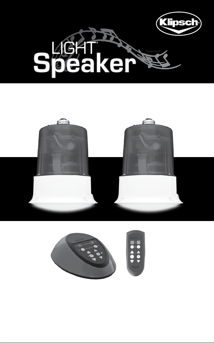
Tech Support: 1-800-KLIPSCH
State-of-the-art LIGHT & SOUND
One complete system that installs in 30 minutes or less!
OWNER’S MANUAL
AND INSTALLATION INSTRUCTIONS
1
Page 2

Tech Support: 1-800-KLIPSCH
The lightning flash with arrowhead symbol, within an equilateral
triangle, is intended to alert the user to the presence of
uninsulated “dangerous voltage” within the product’s enclosure
that may be of sufficient magnitude to constitute a risk of electric
shock to persons.
Le symbole de l’éclair fléché dans un triangle équilatéral, a pour but
d’avertir l’utilisateur de la présence non isolées d’une «tension
dangereuse» dans le boîtier du produit que mai d’une magnitude
suffisante pour constituer un risque d’électrocution pour les
personnes.
The exclamation point within an equilateral triangle is intended
to alert the user to the presence of important operating and
maintenance (servicing) instructions in the literature
accompanying the appliance.
Le point d’exclamation dans un triangle équilatéral sert à alerter
l’utilisateur de la présence d’importantes exploitation et de
maintenance (entretien) dans la documentation accompagnant
l’appareil.
Caution marking is located at the side of the apparatus.
Attention marquage est situé sur le côté de l’appareil.
CAUTION: Risk of Electrical Shock - Use in Dry Locations Only
ATTENTION: Risque de Choc Électrique - Utiliser Seulement Dans des Endroits
Secs
CAUTION: To reduce the risk of electric shock, do not remove cover (or back). No
user servicable parts – refer servicing to qualified service personnel only.
ATTENTION: Pour réduire le risque de choc électrique, ne pas retirer le
couvercle (ou l’arrière). Non utilisateur servicable parts - confier l’entretien de
service qualifie seul le personnel.
WARNING: To reduce the risk of fire or electric shock, do not expose this
apparatus to rain or moisture.
AVERTISSEMENT: Pour réduire le risque d’incendie ou de choc électrique, ne
pas exposer cet appareil sous la pluie et l’humidité.
2
Page 3

Tech Support: 1-800-KLIPSCH
IMPORTANT SAFETY INSTRUCTIONS
1. Read these instructions. Keep these instructions. Heed all Warnings. Follow
all instructions.
2. Do not use this apparatus near water. The apparatus shall not be exposed
to dripping or splashing and that no objects filled with liquids, such as vases,
shall be placed on apparatus.
3. Clean only with a dry cloth.
4. Do not block any ventilation openings. Install in accordance with the
manufacturer’s instructions.
5. Do not install near any heat sources such as radiators, heat registers, stoves,
or other apparatus (including amplifiers) that produce heat.
6. The lamp holder is used as disconnect device. The lamp holder of apparatus
should not be obstructed OR should be easily accessed during intended use.
To completely disconnect the power input, the lamp holder of the apparatus
shall be disconnected from the mains.
7. Only use attachments/accessories specified by the manufacturer.
8. Refer all servicing to qualified service personnel. Servicing is required when
the apparatus has been damaged in any way, such as power-supply cord
or plug is damaged, liquid has been spilled or objects have fallen into the
apparatus, the apparatus has been exposed to rain or moisture, does not
operate normally, or has been dropped.
9. Added weight of the device may cause instability of a free-standing portable
lamp. Use only with portable table lamps in which the distance from the
bottom of the base to the top of the lampholder does not exceed three (3)
times minimum base width. Use only with portable table lamps which are
provided with lamp shades” or the equivalent.
10. This device is not intended for use with emergency exit fixtures or
emergency exit lights
11. NOT FOR USE WHERE EXPOSED TO THE WEATHER
NE PAS EXPOSER AUX INTEMPÉRIES
12. NOT FOR USE IN TOTALLY ENCLOSED RECESSED LUMINAIRES
NE PAS INSTALLER DANS DES LUMINAIRES ENCASTRÉS COMPLÈTEMENT
FERMÉS
3
Page 4
Tech Support: 1-800-KLIPSCH
Congratulations
Thank you for choosing a LightSpeaker® from Klipsch®.
You have chosen one of the most unique, patented,
audio systems in the world. With proper installation and
operation, you will enjoy years of trouble-free use. Klipsch®
sells numerous loudspeakers for use inside or outside your
home. To see the complete Klipsch® product assortment,
visit us on the Internet at: www.Klipsch.com.
4
Page 5

Tech Support: 1-800-KLIPSCH
Table of Contents
System Overview....................................................................................6
What is in this box................................................................................8
Step 1 - Where will you install.........................................................9
Step 2 - Check your connector type...........................................9
®
Step 3 - Test fit your LightSpeaker
...........................................10
Step 4 - Removing the trim ring....................................................11
Step 5 - Installing the trim ring....................................................14
TM
Step 6 - Adjusting the Simple Tabs
.......................................15
Step 7 - Setting the zone and stereo switches...................16
®
Step 8 - Installing your LightSpeakers
...................................20
Step 9 - Pairing....................................................................................21
Step 10 - Plug in your sources......................................................23
®
Step 11 - Enjoy your LightSpeakers
.........................................24
Operating the transmitter & remote control.......................25
Helpful hints...........................................................................................27
More about removing trim rings................................................30
Where to put the transmitter.....................................................33
Attaching the remote wall bracket.............................................33
®
Selecting LightSpeaker
locations..............................................34
Specifications.......................................................................................37
Possible causes of interference.................................................40
Troubleshooting the remote.........................................................41
Warranty...............................................................................................42
Registration Information.................................................................43
FCC Declaration...................................................................................44
Technical Support Information...................................Back Cover
5
Page 6

Tech Support: 1-800-KLIPSCH
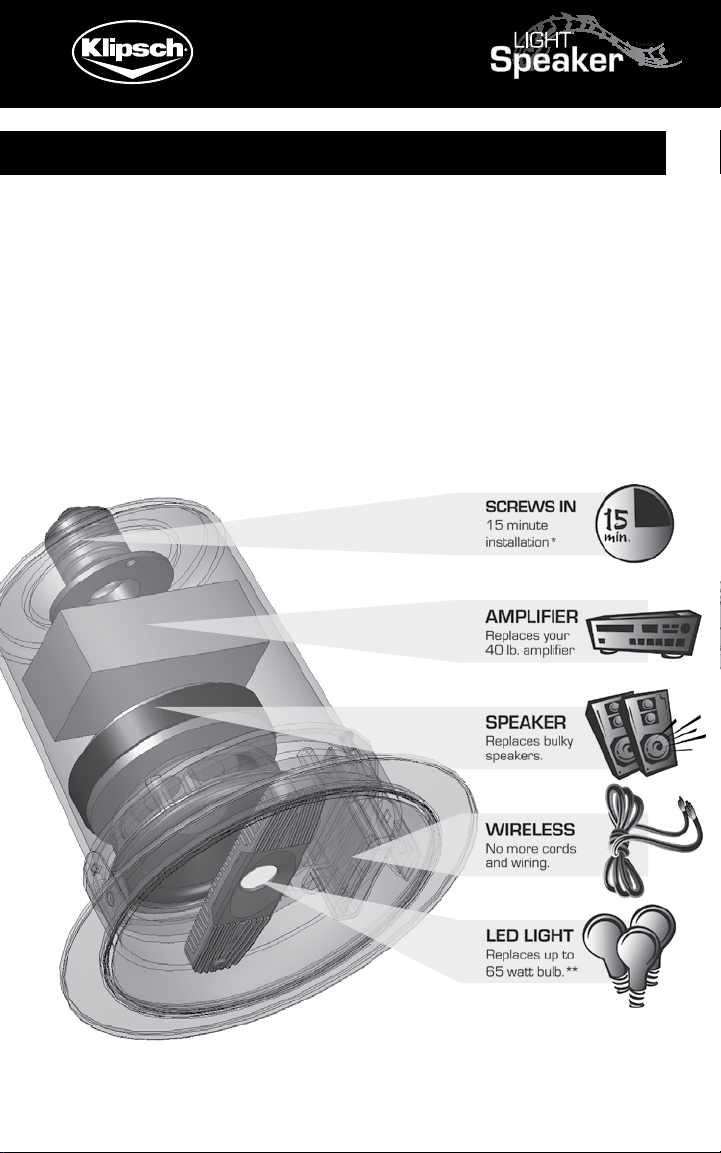
System Overview
This wireless LightSpeaker®
System is intended to install
into any home easily and
without any expensive and
complicated wiring. You can
install a typical system in
your home in a few minutes
and not have to worry about
repairing walls or ceilings.
Plus there is no climbing
into attics or wriggling into
crawl spaces! LightSpeakers®
deliver great sound into any
room in your house, using
your existing wiring and your
recessed lighting fixtures. The
LightSpeaker® installs in a
standard 5“ or 6“ recessed ceiling light fixture common
in most homes. It will replace a standard light bulb
(R-30 or R-40). This unique patented LightSpeaker
®
has full bandwidth audio and “green” lighting together in
one small package. Part of what makes this possible is
the use of a 10W LED to provide the equivalent light of
a 60W incandescent bulb while using 80% less power
than the light bulb it replaced. Consider also that you may
never have to replace this light; an operating life of 25,000
to 40,000 hours means that with average use this light
should easily last 15 to 25 years.
6
Page 7

Tech Support: 1-800-KLIPSCH
Your system can use up to 8 LightSpeakers® to provide
audio and lighting to your entire home. You can even
divide your home into two unique areas where different
music sources, sound and lighting control allow you to add
music with integrated “green” lighting to places you only
dreamed of having it before.
There’s no wiring and no big (or small) speaker boxes.
The wireless transmitter can be centrally located which
will provide audio and, together with the remote, allow you
®
to control your LightSpeakers
from anywhere in your
home. The RF remote and the transmitter base station
will control which source you listen to in a room as well as
the level of the sound and the brightness of the light; this
can be done from anywhere in the house, you don’t need
to be near the transmitter.
Plug two separate audio sources into your transmitter
and deliver the music from your AM/FM Radio, TV or
MP3, or any audio source, to any room in your house.
®
To expand your system, additional LightSpeakers
are
available from your retailer or at www.klipsch.com.
This incredible patented system provides even greater
flexibility to you as the owner; since you can take this
system with you if you move; and when you do, it leaves no
trace (holes that need to be covered) that the system was
ever installed and used.
Please take a few moments to copy down the serial
number and part number found on the side of your
product box onto page 43 of this manual. You will
need them to register your product.
7
Page 8
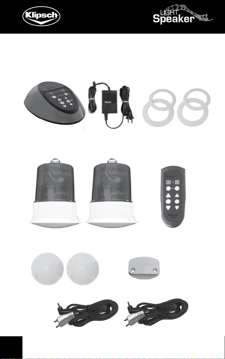
Tech Support: 1-800-KLIPSCH
Take just a minute to be sure you have everything you
need to install your first wireless distributed audio system
from Kadence Designs.
Transmitter Power Cord Large & Small
Trim Rings
LightSpeakers®, & Lens Remote
Lenses Remote Wall Bracket
Attachment Cords
8
Page 9

Instruction Manual
Tech Support: 1-800-KLIPSCH
Step 1:
Decide which lights will be replaced with
LightSpeakers®.
Your Klipsch® LightSpeakers® have been specifically
designed to cover large areas, however if the location of
your fixtures allow you to do so, you should think about
how you use your room and where you are likely to spend
most of your time. Then choose the fixtures that are most
evenly spaced to your preferred listening position.
WARNING!
Turn off circuit breakers to all lighting
fixtures you are working on!
A) Turn off the circuit breaker and light switch, to the
bulbs you intend to replace with LightSpeakers®.
B) Remove the existing light bulb.
Step 2: Check your connector
type. Your Klipsch® LightSpeaker®
is designed to fit into a standard
Edison connector. It will not fit any
other type connector.
STOP!
Check your connector!
9
Page 10
Tech Support: 1-800-KLIPSCH
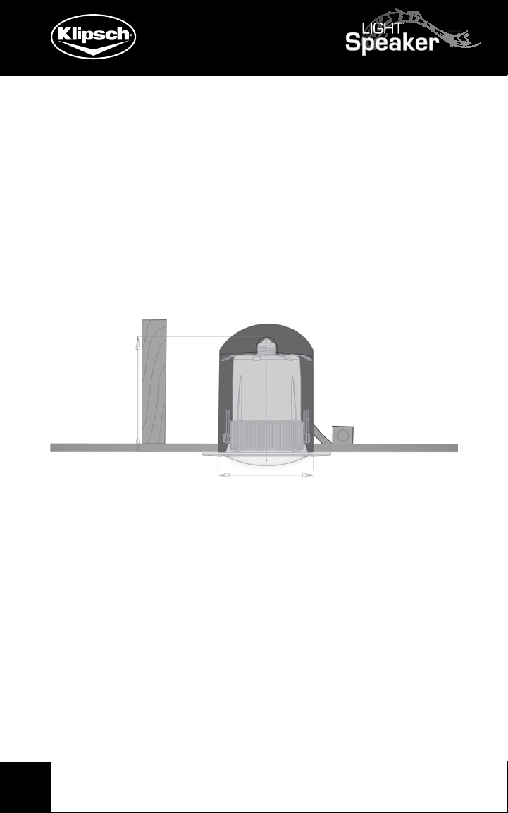
Step 3: Test fit your LightSpeaker®.
Your LightSpeaker® is designed to fit directly into most 5“
(R30) and 6“ (R40) down light cans by simply removing
the existing light and, in the same manner as a light bulb,
re-installing your LightSpeaker® in its place. You may
simply test fit your LightSpeaker®, or you may measure
according to the diagram below, to be certain your
Klipsch® LightSpeaker® will fit directly into your recessed
light fixture.
6.6”
4.75”
This diagram shows the minimum width and depth
necessary to house your LightSpeaker® completely within
the recessed lighting enclosure. The depth can be less if
you do not mind your LightSpeaker® standing out slightly
from the ceiling.
If your LightSpeaker® fits directly into your recessed
lighting fixture without any modifications you can skip
forward to Step 7.
10
Page 11

Tech Support: 1-800-KLIPSCH
If your Lightspeaker® does not fit either because the trim
ring/reflector opening is too small or the lighting fixture is
not set deep enough, please follow the instructions below.
STOP!
Depth is adjustable in
most fixtures! Read on!
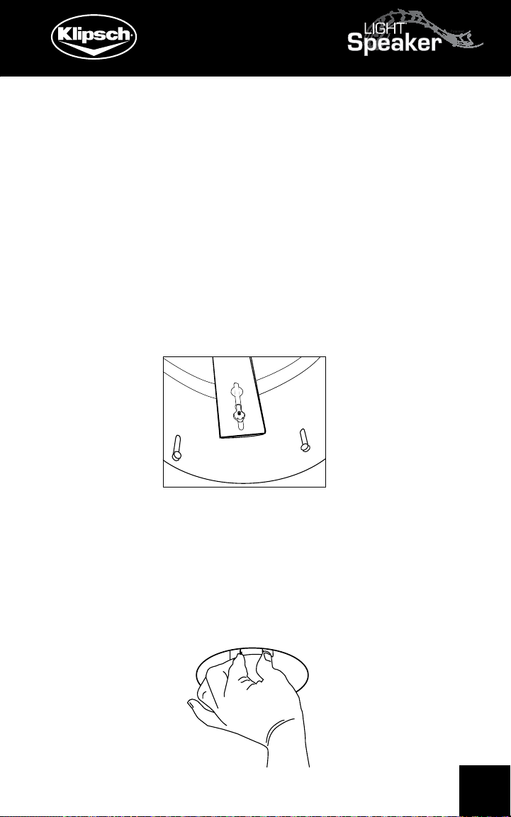
Step 4: Removing the trim ring and any included reflector.
There are many types of recessed light fixtures so it may
be necessary to perform a few simple operations. The goal
is to get your ceiling fixture to look like the picture below.
Remove the trim ring and reflector. Sometimes, especially
in the 5“ fixtures, these are combined units like the figure
below.
11
Page 12

Tech Support: 1-800-KLIPSCH
The attachment here is via a common “V” spring. To
remove simply pinch the two sides of the spring together
and slip out of the “C” shaped brackets on the inside walls
of the lighting fixture.
C shaped
bracket
The trim ring and reflector may also be attached to the
inside of the recessed lighting fixture with small springs.
Reach inside the lighting fixture, grasp the spring at the
top hook, and lift it off of its point of attachment. There
are usually two springs one on either side of the fixture.
For more information on removing this type of trim ring
see the section titled “More on Removing Trim Rings and
Reflector” on page 28 in this manual.
The Edison Socket may also be attached to a socket arm
(L-shaped bracket) or to a socket plate (flat circular piece
of metal). Many times this “arm” or “plate” can be adjusted
via a wing nut to a depth which is suitable for mounting your
LightSpeaker®. In most cases however it is just as easy or
easier to just remove the socket plate all together since it
provides for the quickest and easiest install.
12
Page 13
Tech Support: 1-800-KLIPSCH
Repositioning the socket plate (arm): Loosen the wing
nut just enough to push the plate (arm) as far into the
enclosure as it will go. Retighten the wing nut. Retest
your LightSpeaker® for proper fit. If it fits, remove it again
and go forward to Step 7.
Complete removal of the socket plate: Loosen the wing
nut, turning the “wings” so that they are aligned with the
slot. Slide the plate until the big opening in the slot aligns
with the thick part of the wing nut. Lift the socket plate
free of the wing nut. Slide the wing nut up to the top of
the slot and retighten.
The Edison socket is most often attached to the socket
arm with either 2 screws or via a spring bracket. Either
remove the screws to free the socket, or pinch the spring
bracket to slide it free of the plate (arm). In 5” fixtures
this spring bracket may be attached to a metal bracket
which is itself attached to the trim ring and reflector.
13
Page 14
Tech Support: 1-800-KLIPSCH
HELPFUL TIP!
Save all the parts so if you move, you can
®
replace and take your LightSpeakers
with you.
Step 5: Installing the trim ring.
Your LightSpeaker® comes with their own integrated trim
ring. There are two different sizes. Choose your trim ring
based on either A or B below and place the LightSpeaker®
trim ring over the back of the LightSpeaker®. Be sure
the finished side is facing out. Upon completion of the
install, this trim ring should fit snuggly and uniformly to
the ceiling and should also seat properly around the entire
edge of your LightSpeaker®.
A) The thicker trim ring will be used when your
LightSpeaker® is installed into a 6“ lighting fixture.
14
B) The thinner one when it is installed into a 5” fixture.
As long as the trim ring covers the edges of the lighting
fixture and any rough drywall edges you may use either
trim ring; it will not affect the performance of your
LightSpeaker®.
Page 15
Tech Support: 1-800-KLIPSCH
SimpleTabs
TM
SimpleTabs
TM
Step 6: Adjusting the SimpleTabs™.
Your LightSpeaker® is equipped with a unique mounting
system. The three SimpleTabs™, on the back of
the speaker can be rotated outward and when the
LightSpeaker® is pressed into the housing, hold it
centered and securely in place.
You will now adjust the Simple Tabs™ on the back of the
LightSpeaker® to either A (6” recessed light fixture) or B
(5” recessed light fixture).
If you are installing into a 5” recessed lighting fixture,
rotate each of the SimpleTabs™ out to position “B” on the
top of the LightSpeaker® unit.
15
Page 16

Tech Support: 1-800-KLIPSCH
If you are installing into a 6” recessed lighting fixture,
rotate each of the SimpleTabs™ out to position “A” on the
top of the LightSpeaker® unit.
Step 7: Setting the Zone and L/R Stereo Switches.
A) Set the zone switch on the back of the
LightSpeakers® to one, unless you are setting up a
two zone system. For more on zones see Step 7B:
Setting up a Two Zone System below after completing
B and C below.
B) Set the left/right stereo switch. “L” if it is the left
speaker, “R” if it is the right speaker. For additional
information see Selecting LightSpeaker® Locations.
C) Your LightSpeaker® system allows you to install up
to 4 pair of (or 8 total) speakers. If you are installing
more than one pair of LightSpeakers® you will
probably want to divide your home into zones.
If you are not setting up a two zone system, go to Step 8.
16
Page 17

Tech Support: 1-800-KLIPSCH
Step 7B: Setting up a Two Zone System
Your system allows you to set up two separate zones.
Zones are the different spaces in your home where you
want to listen to music, and are important because, later in
this setup, your Transmitter will automatically seek out and
identify each zone. This in turn will allow you to control the
music and lighting in each zone separately. (See Figure 2A)
17
Page 18

Tech Support: 1-800-KLIPSCH
Assign Zone 1 to one area and Zone 2 to the other
unique area. (See Figure 2B)
18
Page 19

Tech Support: 1-800-KLIPSCH
Here we have assigned Zone 1 to the family room, and
Zone 2 to the kitchen area; these are areas where, even
though you are listening to the same music (the same
source), you may still want to control lighting brightness
and speaker volume separately. For example persons
listening to music in the kitchen may want to turn the
music volume lower while those in the family room may
want the turn the music louder and dim the lights. With
two zones each group can have the music and lights the
way they want them without affecting the other group.
Two-Zone System: Assign each LightSpeaker® to the
zone where it will be installed.
A) Create a sketch of your anticipated zones (ie.
Figures 2A and 2B above).
B) Decide what zone the speaker will go into.
C) Place the LightSpeakers® in their respective zones.
Set the zone switch, on the back of each
LightSpeaker®, to the zone it will be placed.
This LightSpeaker® will be used in Zone 1 and is the right
side of a stereo pair.
19
Page 20

Tech Support: 1-800-KLIPSCH
Step 8: Installing your LightSpeaker® into the recessed
light fixture:
A) Simple Install: If you skipped steps 4-6, and your
LightSpeaker® fits with no modifications, screw it into
the lighting fixture. Test your circuit by turning on the
circuit breaker and light switch from Step 1. If the LED
light does not come on after 5 seconds remove and
reinstall the LightSpeaker®, check your circuit breaker
and try the switch again. You can now skip to Step 9.
B) Simple Tab Install: If you did not skip steps 4-6,
here’s how to use the SimpleTabs™ to install your
LightSpeaker®:
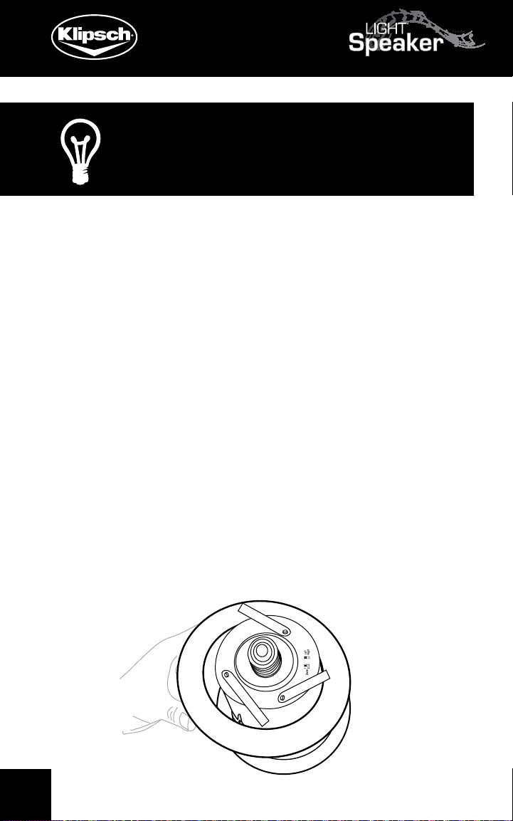
1) Grasp the Edison Socket with one hand, and with the
other hand screw the LightSpeaker® into the socket on
the pigtail. Be careful: Always turn the speaker not the
socket. Turning the socket will twist up the pigtail and
put unneeded stress on the connection.
20
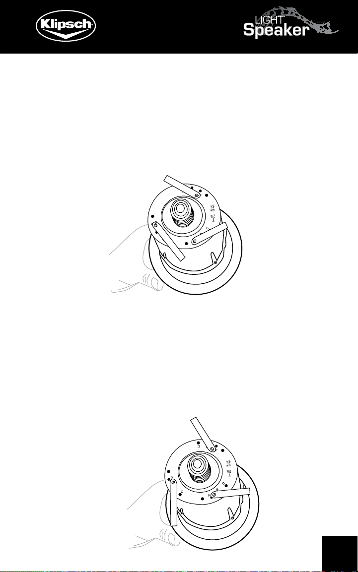
2) Grasp the LightSpeaker® by the light bridge (see
section titled “Removing the Lens” below) and while
holding it level and steady, firmly push it back into the
lighting fixture. It is not necessary to use the light bridge
to install LightSpeaker®, so do so only if you find it
helpful.
Light Bridge
WARNING!
Be careful not to touch the
speaker when grasping the
light bridge.
Page 21

Tech Support: 1-800-KLIPSCH
3) Be certain this trim ring contacts the
ceiling uniformly all of the way around your
LightSpeaker® and that the LightSpeaker® itself
is seated securely into the electrical socket.
Note: sometimes the metal clip that holds the
Edison socket to the socket plate prevents the
LightSpeaker® from seating completely and
making a good electrical connection. If this occurs
simply bend the tabs out and up 1/8” -1/4”.
Step 8B: Removing your LightSpeaker® from a recessed
lighting fixture.
Remove the lens (See Installing and Removing the
Lens), and while pushing up lightly apply a 1/4” turn in a
clockwise direction. Gently pull down on the light bridge.
See “Removing the lens” below.
Step 9: Pairing The Transmitter to the speakers
A) Attach the power cord at the “DC IN” connector on
the back of the Transmitter.
B) Turn on the Power Switch.
C) Pairing - This fully automated process will tell the
transmitter where each LightSpeaker® is located,
allow you to control each zone separately and make
your LightSpeaker® system secure from other nearby
systems. After you have set the zone switch on each
speaker to the correct zone and you have installed
your light speakers into the correct sockets in the
correct zones (i.e. Zone 1 speakers in Zone 1, Zone 2
21
Page 22

Tech Support: 1-800-KLIPSCH
LED Blinks during pairing.
LightSpeakers™ in Zone 2) the job is nearly finished all
that remains is allowing the transmitter discover where
each of the installed LightSpeakers® is located.
1) To pair your LightSpeakers
®
to your
transmitter, turn off all of the light switches in the
®
areas where LightSpeakers
are located.
2) Be sure Transmitter is plugged in and the
power button is on.
3) Push the button marked “PAIRING”. The PAIRING
LED on the transmitter will begin flashing RED.
22
4) Turn on all light switches that your LightSpeakers®
are connected to. The Small LED
light on the speakers will begin
to flash red and will turn green
when the pairing is complete. The
transmitter will automatically find
each speaker and assign it to its
proper zone.
Page 23

Tech Support: 1-800-KLIPSCH
MP3
5) If after 1 minute the LED on the LightSpeaker®
has not turned “GREEN”, repeat steps 1-4.
a) If after 2 attempts the LED on the
LightSpeaker® fails to turn green, try relocating
the Transmitter closer to the LightSpeaker
®
Step 10: Plugging in your sources.
Using the supplied audio cords, plug your MP3, CD Player,
television or other desired sources to the back of the
transmitter.
Attach 1 or 2 audio sources.
A) Locate the sources you want to use. They will have
audio level outputs on them. Typically these are RCA
or stereo headphone type jacks. You will need to have
the proper cable from the source you want to attach
to the Transmitter. You have two choices:
1) RCA to RCA cable
2) RCA to Stereo Mini Plug Cable
23
Page 24

Tech Support: 1-800-KLIPSCH
CAUTION!
Do not use the speaker outputs as
this can damage the transmitter!
B) If you are attaching only one source it may be
attached to either input but may be convenient to
attach to source one.
1) You may use either the mini-plug or the RCA inputs on
either source but only one input may be used at a time.
The remote control and the transmitter are controlled
in exactly the same manner. When you push a button
on the remote contol the small LED next to the button
will light up and remain lit until you push another button
affecting either that zone or that source. The LEDs that
are lit will tell what action the remote or transmitter is
currently set to control.
Step 11: Enjoy your LightSpeakers®!
24
Page 25

Tech Support: 1-800-KLIPSCH
Operating the Transmitter and Remote Control:
The remote control and
the transmitter are
controlled in exactly the
same manner. When
you push a button on the
remote contol the small
LED next to the button
will light up and remain lit
until you push another button affecting either that zone or
that source. The LEDs that are lit will tell what action the
remote or transmitter is currently set to control.
Here are the steps to take to operate the Transmitter
and Remote Control:
A) Press the zone you want to control
B) When the LED next to the button lights, that zone
is active and will be playing the source that is currently
lit. To change to a different source simply press the
source with the “unlit” LED until the LED next to the
source you are choosing lights.
C) Pressing Light once makes the light go On/Off
D) Pressing the + arrow above the light “on” button
will increase the brightness of the light. Pressing the
“-” arrow below the light on/off button will dim the
25
Page 26

Tech Support: 1-800-KLIPSCH
light. The LED will flash when the arrows are pushed
and will turn red and flash quickly when either the
maximum or minimum brightness is reached.
E) Pressing and holding the ON/OFF button turns ON
or OFF all Zones with source 1 playing if turned ON.
F) When Power is applied to a LightSpeaker® by the
wall switch the light defaults to the ON state. This
allows the LightSpeaker’s LED to function like a light
bulb.
NOTE: If your remote does not operate, or you have
purchased additional remotes to be used with the
same transmitter, please see Trouble shooting on
page 41 of this manual.
26
Page 27

Tech Support: 1-800-KLIPSCH
Helpful Hints
Types of Recessed Ceiling Light Fixtures
The most important step you can take to simplify the
installation of your LightSpeakers® is to know, before you
purchase, which type of ceiling light fixtures are installed
in your ceilings. The two most common recessed lighting
fixtures, and the ones that your LightSpeakers™ are
designed to best fit into, are the R30 and the R40 fixtures.
These designations are intended to let you know that these
recessed fixtures are suitable for use with either a 3” (R30)
light bulb or a 4” (R40) bulb. As you might expect, the R30
light fixture is smaller than the R40 and most importantly
the mounting systems are usually quite different. One way
to tell the difference between the two lighting fixtures is to
measure the diameter of the metal lighting fixture at the
point its rim exits the ceiling. An R30 can is very close to 5“
across and an R40 can is closer to 6“ across. The makers
of these fixtures do not adhere to a fixed standard so there
is some variation between the measurements of the various
manufacturers.
In the R30 lighting fixture the Edison connector is most
often attached to a “pigtail”; a short piece of electrical wiring
which allows the connector to hang loose in the can. In the
R40 lighting fixture the Edison connector is nearly always
attached to a “Socket Plate” which can be adjusted up or
down by loosening a wing nut on the side of the fixture.
The R40 lighting fixture nearly always has its Edison
connector firmly attached to a sliding plate which can
be moved up or down in the can by loosening a wing nut.
27
Page 28

Tech Support: 1-800-KLIPSCH
When installing in an R40 light fixture you will want to
loosen this nut and move the plate as far back as possible.
If this wing nut is properly tightened, it will be sufficient to
®
securely hold your LightSpeaker
permanently in place.
The R30 light fixture uses another entirely different method
to secure the LightSpeaker® to the down lighting fixture.
It is held by means of two wire “V springs”. These are
sometimes but not always the springs that hold the trim
ring to the light fixture; more often they are the two wing
shaped springs that when viewed out of the light fixture
form, as the name implies, a spread out letter “V”. If you
have removed the existing trim ring and any included
reflector, then you will have already encountered these “V
springs” and know how they operate. Do not confuse these
springs with the “coil springs” which attach the reflector to
the down lighting fixture.
Installing and Removing the Lens:
28
A) Removal BEFORE your LightSpeaker® is installed.
1) While holding the LightSpeaker® in the palm of your hand
rotate the unit until one of the holding tabs is facing up.
2) Using a fingernail, common screwdriver or other small
flat object, gently push down and then out on the tab, easing
it out through the opening in the
LightSpeaker® housing.
Page 29

Tech Support: 1-800-KLIPSCH
CAUTION: Do not touch the LED or Speaker Baffle
with the lens off when the unit is hot, allow the unit
to cool down before touching the baffle.
3) When the lens pops up, gently pry it away from
the housing, being gentle and making sure not to
break the tabs.
B) Removal of the lens AFTER your LightSpeaker® has
been installed.
1) There are three small indentations around the
lens; with a small tip common screwdriver, nail file,
paper clip or similar object, gently slip the tip into
the indentation and pry the lens outward until the
retaining tabs pull free.
2) To re-install the lens, align the tabs and the
hole for the pairing LED, then push gently until the
locking tabs snap into place.
29
Page 30

Tech Support: 1-800-KLIPSCH
More About Removing Trim Rings
The trim ring is the narrow ring of plastic (usually) that
contacts the ceiling and gives your ceiling light, and your
LightSpeaker® a finished look when butted against the
ceiling drywall. Your LightSpeaker® comes equipped with
its own paintable trim ring. If your LightSpeakers® do not
fit directly into the recessed lighting fixture, you may need
to remove the trim ring and any included reflector. This
is not a difficult process however exercising a little care
will make the job look better when you are finished. We
suggest that you turn off the light switch and the circuit
breaker prior to beginning any work.
With the old light bulb removed determine whether your
hand will fit easily through the hole into the interior of the
lighting fixture. If it does, you will likely not require any
special tools to complete the process. Simply grasp one
end at a time of each of the two coil springs and lift them
free of the retaining clips in the fixture housing. See figure
below for the various ways that these springs may be
attached to the housing.
30
Page 31

Tech Support: 1-800-KLIPSCH
A) If your hand does not fit easily through the hole
you may find the job easier if you have either a “spring
removal tool” or even a “long nose pliers”. Both are
available at your local hardware store.
Klein Spring Removal Tool Long Nosed Pliers
B) If your hand does not fit through the opening, one
of these tools can be used to remove the coil springs
that are used to hold the trim ring and reflector to the
recessed light housing.
Coil Spring
C) The trim ring may have been previously painted to
match the color of the ceiling, and this paint may be
gluing or otherwise bonding the trim ring to the ceiling
drywall. If this is the case, you may want to break the
paint bond by carefully cutting around the edge with a
utility knife.
1) After you have cut the paint bond at the edge
of the trim ring use a small blade (1” or smaller)
putty knife to gently slide under the trim ring and
lift it free of the underlying surface.
31
Page 32

Tech Support: 1-800-KLIPSCH
D) V Springs. Another method of holding various
parts to a recessed lighting fixture, is the use of “V”
springs. Like the name implies they are shaped in the
form of a V. When compressed (pinching the two legs
of the V) and fitted into the “V Spring Clip” on the side
of the metal lighting fixture they form a spring that
will slide up and down several inches. When attached
to the trim ring (and or reflector) the trim ring can
be pulled away from the ceiling 3” or 4“, allowing you
to reach in, pinch the two “legs of the V” and release
the spring, trim ring and reflector from the recessed
housing.
1) Once the coil springs (or “V” springs) are
removed from the clip on the lighting fixture, the
trim ring, reflector, and the springs should easily
drop free and can be placed aside.
E) How to remove coil springs: By gently pulling on
the spring and a slight twist, maneuver the end of the
spring out of the retaining clip. Remove both springs.
Quite often this is easily done with your fingers but is
made easier with a spring removal tool or sometimes
a pair of long nose pliers.
We recommend you store all parts, so that they can
be replaced should you ever wish to remove your
LightSpeaker®, for example when taking them with you
during a move.
32
Page 33

Tech Support: 1-800-KLIPSCH
Where to put the transmitter?
Typically, the perfect place for your transmitter is near
your home entertainment system, if you have one.
If you don’t have a home audio system then you can
chose a place that is centrally located to the rooms
you will be transmitting the audio to. Remember the
range of the system is approximately 50’ radius circle
of the transmitter, so as long as the distance from the
transmitter to the farthest speaker in any direction is less
than 50’, the placement of the transmitter is up to you.
Note: There is a maximum of two transmitters in one
home and they need to be 25’ apart.
Attaching the remote wall bracket
1) Identify where on the wall you want the remote to
hang.
2) Place the remote in this position and mark a small
line in pencil where the top of the hanging bracket on
the remote hits the wall.
3) Mount the Remote Wall Hanging Bracket to the
wall using the two (2) supplied screws.
4) You are now ready to use the Wall Hanging
Bracket to keep your remote in an easily accessible
position as you enter or exit a room.
33
Page 34

Tech Support: 1-800-KLIPSCH
Selecting LightSpeaker® Locations
Survey your home to determine the location of 5” and 6”
recessed lighting fixtures. As long as these are wired to
the home’s electricity through a common light switch,
they should work perfectly. If you have multiple locations
within one room, try to space the speakers as far as part
as possible, this will provide the best stereo image and
the best sound. In general, the maximum spacing of the
speakers is determined by ceiling height. Using the table
below, try to space speakers at the distances stated or
closer together. If you cannot place them closer than
the recommended maximum spacing, do not worry, your
sound quality will still be good. In some large rooms you
may need more than one pair of speakers.
Ceiling Height Recommended Max Speaker Spacing
8’ 8’
10’ 13’
12’ 20’
14’ & higher 25’
NOTE: There are no direct controls for the sources. From
the remote we cannot turn them on or off or control what
they are playing.
34
Page 35

Tech Support: 1-800-KLIPSCH
To illustrate how the Transmitter and Remote work, here
are a few examples:
To play Source 1 in Zone 1
Press Zone 1 Press Source 1
To play Source 2 in Zone 1 after the source 1 is playing
Press Zone1 Press Source 2
To play Source 2 in Zone 2
Press Zone 2 Press Source 2
35
Page 36

Tech Support: 1-800-KLIPSCH
To play Source 1 in Zone 2 after already playing source 2
Press Zone 2 Press Source 1
To turn off lights in Zone 1
Press Zone 1 Press light button once
To Dim/Brighten
lights in Zone 1
Press Zone 1
Press light button up
arrow and hold it, the
light will increase in
brightness, and when
the light is at the level
you want, release the
button. When you reach maximum
brightness the lighting LED will flash
quickly. To decrease the brightness
press the light button down arrow
and hold till the desired brightness is
reached.
Remember: First Zone, then Action and you will be able
to use the Remote and Transmitter functions intuitively.
36
Page 37

Tech Support: 1-800-KLIPSCH
Specifications
LED Light
• 10W super bright LED provides a sharp crisp light
that is easy on the eyes.
• LED outputs the light suitable to replace up to a
60W incandescent bulb
• Long Lasting LED is rated for over 25,000 to
40,000 hours of use (15 to 20 years average use)
• LED Light is fully dimmable and is controlled
from either the remote or the light button on the
transmitter
Wireless Transmitter
Receives a 2.4 GHz wireless stereo signal broadcast
from the Transmitter and depending on the zone
assigned to the speaker and the left or right audio
channel selected, the receiver sends the correct signal
®
to each LightSpeakers
on-board digital amplifier.
Digital Amplifier & Switch Mode Power Supply
• The E26 standard Edison Screw allows the unit to
attach to any standard light fixture socket.
• The high efficiency switch mode power supply
delivers power to the LED and the digital
amplifier without generating a lot of heat.
• 20W high performance low distortion digital
amplifier provides energy efficient sound
• The on-board Digital Signal Processing delivers
®
customized audio to each LightSpeaker
giving big
speaker sound in a small speaker.
37
Page 38

Tech Support: 1-800-KLIPSCH
Loud Speaker
• 2.5” high performance custom engineered woofer with
Micro Cellulose Polymer treated cone material provides
even coverage and smooth natural sounding audio
reproduction
• Integrated high frequency disperser.
Accessories
• Optional flange allows LightSpeaker
®
to fit into either
5” (R30) or 6” (R40) recessed lighting fixtures.
• Frosted Lens is acoustically transparent
Transmitter
• 2 sets of RCA or 3.5mm stereo jack line level audio
inputs allows 2 separate sources to be used
• Wireless simultaneous transmission to two separate
zones of loudspeakers
• Controls LED light in each zone independently
• Controls Audio level and source in each zone
independently
• Simple front panel controls allow easy adjustment of
the speakers’ sound
• Wireless transmitter can send audio to
loudspeakers 50’ to 100’ in any direction
Accessories
• RF remote allows control of sound 50’ to 100’ away
from transmitter depending on the environment
38
• RF Remote allows selection of zone and source
which allows you to adjust audio in each zone
• DC power supply for transmitter
Page 39

Tech Support: 1-800-KLIPSCH
5” LightSpeaker® Specifications
Woofer 2.5” Micro Cellulose
Light Brightness 10W LED
Wireless Reception 2.4 GHz proprietary signal
Frequency Response (+/- 3 dB) 90 Hz - 20 kHz
Amplifier Power 20W
Max SPL 93 dB SPL
Dimensions
LightSpeaker® depth (w/out Edison Screw) 5.3” (135.3 mm)
LightSpeaker® diameter (without Flange) 5.1” (130.0 mm)
LightSpeaker® diameter (with Flange) 7.2” (182.8 mm)
Depth without socket - no lens 5.5” (140.0 mm)
Depth with Socket - no lens 6.6” (167.2 mm)
Depth without socket with lens 6.1” (153.8 mm)
Depth with Socket with lens 7.1” (181.0 mm)
OD of 6” Flange 7.6” (192.0 mm)
OD of 5” Flange 6.7” (171.2 mm)
Weight 2.51 lbs (1.14 kg)
Transmitter & Remote Specifications
Transmitter Sources 2
Discrete Transmitter Zones 2
Audio Transmission Frequency 2.4 GHz proprietary
RF Remote Transmission Frequency 908 Mhz
Audio Transmitter range (omni-directional) 50’ to 100’
depending on environment
RF Remote range (omni-directional) 50’ to 100’
depending on environment
AC Power 90 VAC to 240 VAC
Dimensions
Transmitter 5.9” (151 mm) W x 7” (177 mm) L x 2.4” (60 mm) H
Remote: 2” (52 mm) W x 5.1” (130 mm) L x 1.2” (30 mm) H
39
Page 40

Tech Support: 1-800-KLIPSCH
Possible causes of interference with your
LightSpeaker® System
A) Metal studs, in fact any metal wall material, can
cause the signal to be diminished or lost. This may
also be a problem if your wall paper happens to be
a foil type or have metal fibers in it.
B) Microwave ovens, when operating, may degrade
or interrupt the signal from your transmitter. Usually
this will only be a problem for those speakers in close
proximity to the microwave. For best results, do not
locate the transmitter near your microwave.
C) Certain portable phones operating in the 2.4
Ghz range, wireless computer routers, and other
consumer electronics and toys using 2.4 Ghz may
cause interference when operated too close to either
the transmitter or the speakers.
40
Page 41

Tech Support: 1-800-KLIPSCH
Troubleshooting the Remote
If your remote does not operate when any of the buttons
are pushed:
A) Check the batteries to be certain that they have
a charge. Replace them if necessary.
The remote may need to be paired to the transmitter.
To pair the transmitter:
A) Press the pairing button on the back of the
transmitter. Five lights on the transmitter keypad
(Zone 1, Zone 2, Source 1, Source 2 and the pairing
light in the front) will light up and begin flashing;
B) Stand 2’ - 4’ away from the transmitter with the
remote. Press and hold the Zone 2 key on the remote
for about 4 seconds. All lights will stop flashing, then
pairing is complete. In the event this does not work,
try again, beginning at Step A.
If the remote still does not operate, try pairing one
more time or contact us at www.Klipsch.com.
41
Page 42

Tech Support: 1-800-KLIPSCH
Warranty - Home and Commercial Audio (U.S.)
The Warranty below is valid only for sales to consumers in the United States.
KLIPSCH, LLC (“KLIPSCH”) warrants this product to be free from defects
in materials and workmanship (subject to the terms set forth below) for a
period of two (2) years from the date of purchase for the LED light and one
(1) year from the date of purchase for the rest of the components. During
the Warranty period, KLIPSCH will repair or replace (at KLIPSCH’s option)
this product or any defective parts (excluding electronics and amplifiers). For
products that have electronics or amplifiers, the Warranty on those parts is
for a period of one (1) year from the date of purchase.
To obtain Warranty service, please contact the KLIPSCH authorized dealer
from which you purchased this product. If your dealer is not equipped to
perform the repair of your KLIPSCH product, it can be returned, freight
paid, to KLIPSCH for repair. Please call KLIPSCH at 1-800-KLIPSCH for
instructions. You will need to ship this product in either its original packaging
or packaging affording an equal degree of protection.
Proof of purchase in the form of a bill of sale or receipted invoice from an
authorized dealer, which is evidence that this product is within the Warranty
period, must be presented or included to obtain Warranty service.
This Warranty is invalid if (a) the factory-applied serial number has been
altered or removed from this product or (b) this product was not purchased
from a KLIPSCH authorized dealer. You may call 1-800-KLIPSCH to confirm
that you have an unaltered serial number and/or you purchased from a
KLIPSCH authorized dealer.
This Warranty is only valid for the original purchaser and will automatically
terminate prior to expiration if this product is sold or otherwise transferred
to another party.
This Warranty does not cover cosmetic damage or damage due to misuse,
abuse, negligence, acts of God, accident, commercial use or modification of,
or to any part of, the product. This Warranty does not cover damage due
to improper operation, maintenance or installation, or attempted repair by
anyone other than KLIPSCH or a KLIPSCH dealer which is authorized to do
KLIPSCH warranty work. Any unauthorized repairs will void this Warranty.
42
Page 43

Tech Support: 1-800-KLIPSCH
This Warranty does not cover product sold AS IS or WITH ALL FAULTS.
REPAIRS OR REPLACEMENTS AS PROVIDED UNDER THIS WARRANTY ARE
THE EXCLUSIVE REMEDY OF THE CONSUMER. KLIPSCH SHALL NOT BE
LIABLE FOR ANY INCIDENTAL OR CONSEQUENTIAL DAMAGES FOR BREACH
OF ANY EXPRESS OR IMPLIED WARRANTY ON THIS PRODUCT. EXCEPT TO
THE EXTENT PROHIBITED BY LAW, THIS WARRANTY IS EXCLUSIVE AND IN
LIEU OF ALL OTHER EXPRESS AND IMPLIED WARRANTIES WHATSOEVER,
INCLUDING BUT NOT LIMITED TO, THE WARRANTY OF MERCHANTABILITY
AND FITNESS FOR A PRACTICAL PURPOSE.
Some states do not allow the exclusion or limitation of incidental or
consequential damages or implied warranties so the above exclusions may
not apply to you. This Warranty gives you specific legal rights, and you may
have other rights, which vary from state to state.
OUTSIDE THE UNITED STATES AND CANADA
The warranty on this product if it is sold to a consumer outside of the
United States or Canada shall comply with applicable law and shall be the
sole responsibility of the distributor that supplied this product. To obtain
any applicable warranty service, please contact the dealer from which you
purchased this product, or the distributor that supplied this product.
Questions? Call us!
Have a question about your Klipsch speakers? Talk to the people who
know them best! We’re waiting to hear from you!
1-800-KLIPSCH
Email us!
If you prefer, your questions and comments can be submitted by email,
too; you can count on rapid response and clear, concise answers.
support@klipsch.com
WRITE THE PART NUMBER AND SERIAL NUMBER FROM YOUR
PRODUCT BOX HERE AND RETAIN FOR PRODUCT REGISTRATION
Part Number:______________________________________________
Serial Number:_____________________________________________
Register your product online
at www.klipsch.com/register.
43
Page 44

Tech Support: 1-800-KLIPSCH
THIS DEVICE COMPLIES WITH FCC RULES PART 15.
Operation is subject to the following two conditions:
(1) this device may not cause harmful interference and
(2) This device must accept any interference received including that may
cause undesired operation.
This equipment has been tested and found to comply with the limits for a
Class B digital device, pursuant to Part 15 of the FCC Rules. These limits
are designed to provide reasonable protection against harmful interference
in a residential installation. This equipment generates, uses and can radiate
radio frequency energy and, if not installed and used in accordance with
the instructions, may cause harmful interference to radio communications.
However, there is no guarantee that interference will not occur in a particular
installation. If this equipment does cause harmful interference to radio or
television reception, which can be determined by turning the equipment off
and on, the user is encouraged to try to correct the interference by one or
more of the following measures:
-- Reorient or relocate the receiving antenna.
-- Increase the separation between the equipment and receiver.
-- Connect the equipment into an outlet on a circuit different from that to
which the receiver is connected.
-- Consult the dealer or an experienced radio/TV technician for help.
THIS DEVICE COMPLIES WITH THE CANADIAN ICES-003
CLASS B SPECIFICATION
CET APPAREIL EST CONFORME AVEC LE CIEM-003 DU
CANADA CLASSE B SPÉCIFICATION
CAUTION:
Changes or modifications not expressly approved by the party
responsible for compliance could void the user’s authority to operate
the equipment
ATTENTION:
Les changements ou modifications non expressément approuvés par
la partie responsable de la conformité pourraient annuler l’autorité
de l’utilisateur à faire fonctionner l’équipement
44
Page 45

NOTES:
Tech Support: 1-800-KLIPSCH
45
Page 46

NOTES:
Tech Support: 1-800-KLIPSCH
46
Page 47

NOTES:
Tech Support: 1-800-KLIPSCH
47
Page 48

Tech Support: 1-800-KLIPSCH
Klipsch Worldwide Corporate Headquarters
3502 Woodview Trace, Suite 200
Indianapolis, IN 46268
For more detailed installation instructions go to
www.klipsch.com
Klipsch Technical Support
Toll Free: 1-800-KLIPSCH (1-800-554-7724)
Monday - Friday, 8:00 AM - 5:30 PM EST
E-mail: technicalsupport@klipsch.com
If you want to expand your light and sound system to
additional rooms, replace existing lights with LED lights
only or enjoy the same music outdoors as well as
indoors, visit www.klipsch.com.
Protected under multiple US and or international issued and pending patents
48
Revision: D
Date: 11/22/2009
 Loading...