

KLING & FREITAG VIDA M Series, VIDA M 110, VIDA M 110 S, VIDA M 220, VIDA M 220 S User Manual
Page 1
EN | | VERSION 1.1 | 08/19/2019
USER‘S MANUAL
K&F VIDAM
Page 2

Page 3

User‘s Manual K&F VIDAM
Table of Content
Chapter / Content Page
1 Introduction 5
1.1 Icons Used 5
1.2 About this user's manual 5
2 Product Description 6
2.1 Intended Use 6
2.2 Versions 6
2.3 System requirements 7
2.4 Items Included 7
2.4.1 Items Included VIDA M 110 / 110 S 7
2.4.2 Items Included VIDA M 220 / 220 S 7
2.5 Overview of VIDA M 110 / 110 S Parts 8
2.6 Overview of VIDA M 220 / 220 S Parts 9
2.7 Front-panel indicator 10
2.8 Accessories 11
2.9 Dimensions 12
2.9.1 Dimensions VIDA M 110 / 110 S 12
2.9.2 Dimensions VIDA M 220 / 220 S 13
2.10 Technical Specifications 14
2.10.1 Technical Specifications VIDA M 110 14
2.10.2 Technical Specifications VIDA M 110 S 15
2.10.3 Technical Specifications VIDA M 220 16
2.10.4 Technical Specifications VIDA M 220 S 17
2.11 Measuring Diagrams 18
3 General Safety Instructions 20
4 Initial installation of VIDA M 220 / 220 S modules 21
5 Wiring 24
5.1 Terminal positions and purpose 24
5.2 Kardioid 24
5.2.1 AC power inlet 24
5.2.2 Audio terminals 25
5.2.3 GPIO 26
6 GPIO specifications 27
6.1 GPI 27
6.1.1 GPI internal wiring: 28
6.2 GPO 29
7 Systemlatency 30
7.1 Dante latency 30
7.1.1 Example 30
7.1.2 Changing between Dante redundancy operating modes 31
©KLING & FREITAG GMBH Version 1.1 Page 3 of 40
Page 4

User‘s Manual K&F VIDAM
7.1.3 Setting up Dante latency with an additional hop 31
8 Initial Operation 32
9 Updates 34
9.1 Firmware Update 34
9.2 Dante Update 35
10 Care and Maintenance 36
11 Transportation and Storage 37
12 Disposal 37
12.1 Germany 37
12.2 EU, Norway, Iceland, and Liechtenstein 37
12.3 All Other Countries 37
13 EC Declaration of Conformity 38
Page 4 of 4 Version 1.1 ©KLING & FREITAG GMBH
Page 5

User's Manual K&F VIDAM
WARNUNG
VORSICHT
HINWEIS
TIPP
1
Introduction
1.1 Icons Used
This icon indicates a risk of injury or death. Not following these instructions may result in serious health problems including potentially fatal injuries.
This icon indicates a possibly dangerous situation. Not following these instructions may cause
minor injuries or damage.
This icon marks instructions for proper use of the described products. Not following these instructions may cause malfunctions or damage.
This icon marks information provided for simplified use of the described products.
1.2 About this user's manual
EN | Translation of the original instructions
All KLING&FREITAG manuals are originally authored in German.
© KLING&FREITAG GmbH, all rights reserved.
All specifications regarding the features of the described products and applicable safety guidelines provided in this manual are based on information available at the time of publishing.
We assume no responsibility for technical specifications, dimensions, weights, and properties.
All information in this manual is subject to change without notice.
To ensure safe operation, all persons using the speaker system must have access to
these user's manual and all other relevant material during installation. Ohne dieses
gelesen, verstanden und griffbereit vor Ort zu haben, darf das Lautsprechersystem
weder aufgebaut noch eingesetzt werden.
KLING&FREITAG spare manuals are separately available for order or can be downloaded
from our website: www.kling-freitag.de
Contact Us: info@kling-freitag.de
KLING & FREITAG GMBH, Junkersstr. 14, D-30179 Hannover
Phone +49 511 96 99 70, fax +49 511 67 37 94 (other countries)
© KLING & FREITAG GMBH Version 1.1 Page 5 of 40
Page 6
User's Manual
WARNUNG
HINWEIS
VIDA M1.119.08.201908/19/2019
K&F VIDAM
2 Product Description
2.1 Intended Use
Be sure to use the VIDAM speaker system for stationary indoors installations only. The system
is not designed for repeated assembly, reconfiguration, disassembly, or transport.
Risks imposed by falling or overturning parts
Be sure to install, suspend, fasten, and use Kling &<###Space: 1##>Freitag speakers only using the designated fixtures as specified in this document.
Never down-tilt speakers mechanically.
Possible malfunctions
Never operate the speaker in an environment where the temperature exceeds 45 °C / 113 °F.
Never operate the speaker in places exceeding an altitude of 2,000 meters / 6,000 ft.
Make sure that the humidity is between 10% and 90%.
This product is not designed for use in corrosive environments.
Potential interference with household appliances
This device is not designed for home use.
Any use not described in this User’s Guide is not an intended use.
2.2 Versions
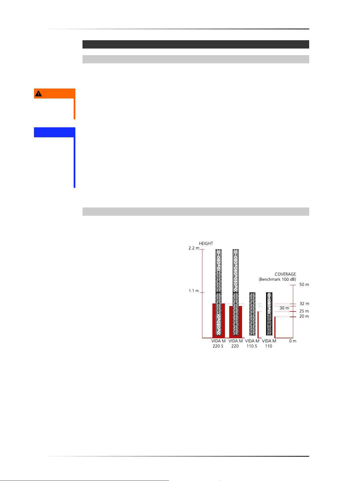
VIDAM is available in four versions designed for different applications and transmission ranges.
VIDA M 110
•
Asymmetrical design
•
Transmission range: approx. 20
meters
•
Height: 1.1 meters
VIDA M 110 S
•
Symmetrical design
•
Transmission range: approx. 25
meters
•
Height: 1.1 meters
VIDA M 220
•
Asymmetrical design
•
Transmission range: approx. 30
meters
•
Height: 2.2 meters
VIDA M 220 S
•
Symmetrical design
•
Transmission range: approx. 32
meters
•
Height: 2.2 meters
Page 6 of 40 Version 1.1 © KLING & FREITAG GMBH
Page 7

User's Manual K&F VIDAM
2.3 System requirements
•
Mounting hardware
•
Computer running Windows 8, 8.1, or 10
•
VIDAApp
The VIDAApp required for setting up the speaker system is freely available at the Windows Store.
For this purpose, visit the Microsoft App Store and search for VIDA App.
For more information, refer to the VIDAApp User's Manual, which is available for download at our website.
www.kling-freitag.de
•
Audio source connected to Analog, AES 3, or Dante.
2.4 Items Included
2.4.1 Items Included VIDA M 110 / 110 S
•
VIDA M 110 / 110 S speaker (1 piece)
•
Counterbore caps (12 pieces)
•
Sealing plate for the connector panel (1 piece)
•
Countersunk screw M4x10 for fixing the sealing plate (7 pieces)
•
3-pin power connector (1 piece)
•
9-pin audio-in connector (1 piece)
•
15-pin GPIO connector (1 piece)
•
Cable tie (3 pieces)
•
Loctite 2400 (5 ml)
•
User’s manual (1 piece)
2.4.2 Items Included VIDA M 220 / 220 S
•
Passive module for VIDA M 220 or VIDA M 220 S (1 piece)
•
Active module for VIDA M 220 or VIDA M 220 S (1 piece)
•
Mounting plate for fastening the modules (2 pieces)
•
Countersunk screw M6x10 for fastening the modules (12 pieces)
•
Counterbore caps (12 pieces)
•
Sealing plate for the active-module connector panel (1 piece)
•
Sealing plate for the passive-module connector panel (1 piece)
•
Countersunk screw M4x10 for fastening the sealing plates (14 pieces)
•
3-pin power connector (1 piece)
•
9-pin audio-in connector (1 piece)
•
15-pin GPIO connector (1 piece)
•
Cable tie (3 pieces)
•
Loctite 2400 (5 ml)
•
User’s manual (1 piece)
© KLING & FREITAG GMBH Version 1.1 Page 7 of 40
Page 8
User's Manual
VIDA M1.119.08.201908/19/2019
K&F VIDAM
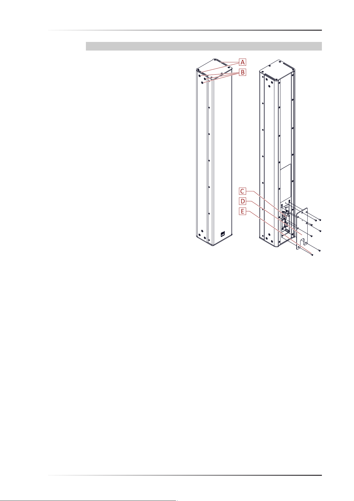
2.5 Overview of VIDA M 110 / 110 S Parts
[A] Inlet for connecting mounting
hardware (also available at the
bottom)
[B] Bores for fastening mounting
hardware. Can be sealed using
the supplied caps when not in
use.
[C] Connector panel
[D] Sealing plate for connector panel
[E] Screws for fastening the sealing
plate:
7 x Countersunk screw M4x10,
hexagon socket wrench IS2,5 (7
pieces)
Page 8 of 40 Version 1.1 © KLING & FREITAG GMBH
Page 9
User's Manual K&F VIDAM
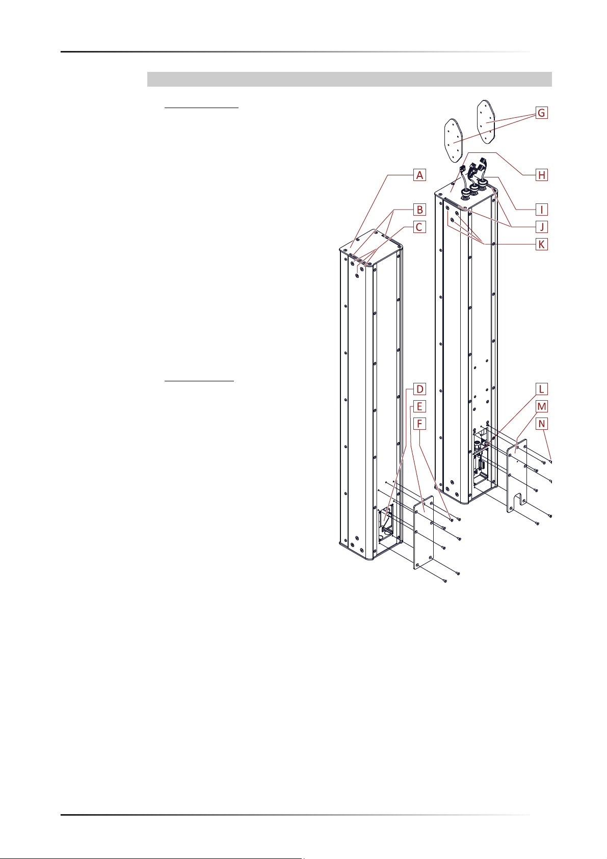
2.6 Overview of VIDA M 220 / 220 S Parts
[A] Passive module
[B] Inlet for connecting mounting
hardware (bottom inlet for connecting the active module)
[C] Bores for fastening mounting
hardware. Can be sealed using
the supplied caps when not in
use. Use the bores at the bottom
for connection with the active
module [H].
[D] Connector panel for fastening
the active module
[E] Sealing plate for the passive-
module connector panel
[F] Screws for fastening the sealing
plate:
7 x Countersunk screw M4x10,
hexagon socket wrench IH2.5
[G] Fastener for connecting the pas-
sive module to the active module
[H] Active module
[I] Cable with connectors and
grommets for connecting the
passive module. The VIDA M 220
has only one single cable!
[J] Inlet for connecting to the pas-
sive module (inlet at the bottom
is for fastening mounting hardware)
[K] Bores for fastening the active
module [A]. The bores at the
bottom are for fastening mounting hardware. Can be sealed using the supplied caps when not
in use.
[L] Connector panel
[M] Sealing plate for the active-mod-
ule connector panel
[N] Screws for fastening the sealing
plate:
7 x Countersunk screw M4x10,
hexagon socket wrench IH2.5
© KLING & FREITAG GMBH Version 1.1 Page 9 of 40
Page 10

User's Manual
VIDA M1.119.08.201908/19/2019
K&F VIDAM
2.7 Front-panel indicator
Each VIDAM features an LED indicator located behind the front grille. You can turn the LED
on and off using the VIDAApp in order to identify a specific VIDAM speaker.
The indicator color shows the following statuses:
•
Power-up (blue): The speaker is being powered up and will be ready for operation shortly.
•
Beam error (red-lit): The speaker has been powered up successfully and is ready for operation; however, the sound-ray setup needs to be checked.
•
Identification (green): The speaker is part of the selected speaker group.
•
Error (flashing red and green): Configuration error. Perform a firmware update. See chapter »Firmware Update«, page 34.
Page 10 of 40 Version 1.1 © KLING & FREITAG GMBH
Page 11

User's Manual K&F VIDAM
2.8 Accessories
VIDAM wall bracket
VIDAM flying frame
VIDAM adapter,
suitable for VIDA M 110 / 110 S
© KLING & FREITAG GMBH Version 1.1 Page 11 of 40
Page 12
User's Manual
VIDA M1.119.08.201908/19/2019
K&F VIDAM
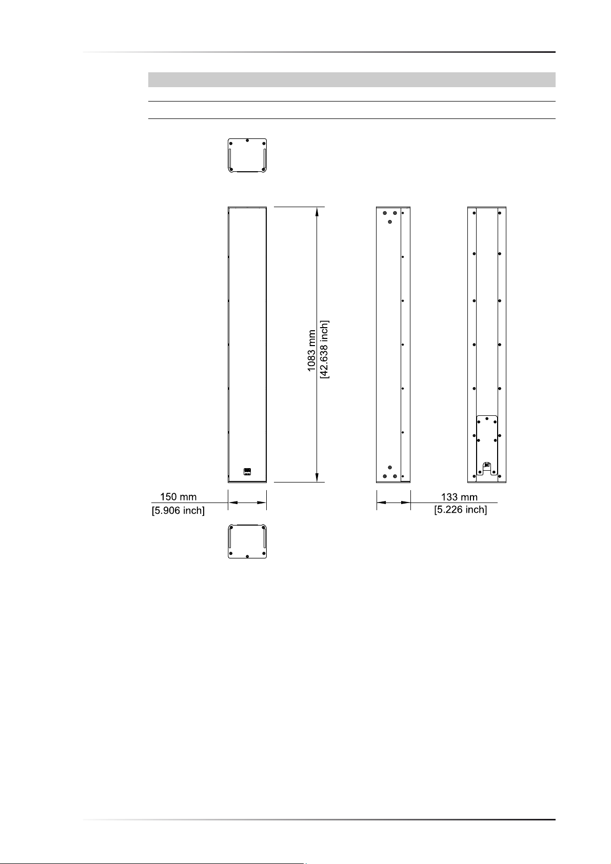
2.9 Dimensions
2.9.1 Dimensions VIDA M 110 / 110 S
Page 12 of 40 Version 1.1 © KLING & FREITAG GMBH
Page 13

User's Manual K&F VIDAM
2.9.2 Dimensions VIDA M 220 / 220 S
© KLING & FREITAG GMBH Version 1.1 Page 13 of 40
Page 14

User's Manual
VIDA M1.119.08.201908/19/2019
K&F VIDAM
2.10 Technical Specifications
2.10.1 Technical Specifications VIDA M 110
Concept
Input signal
Frequency range @-10 dB
Frequency range @±3 dB
Horizontal coverage angle
(nominal)
Coverage angle vertical
Max. SPL
Components
Connectors
AUX OUT
Active 2-way coaxial line array with electronic beam
steering
Each speaker is fed through a dedicated DSP/amp channel.
95 Hz – 22 kHz
125 Hz – 21 kHz
90° nominal
Continuously adjustable spread angle up to 90°.
±45° steering angle
131 dB
16 × 1” dome tweeters
8 × 4” bass/midrange drivers
DANTE™ (primary/secondary)/remote (RJ45), AES67
compliant, AES/EBU input (9-pin Phoenix terminal block),
Analog input (9-pin Phoenix terminal block),
GPIO (15-pin Phoenix terminal block),
AUX OUT (9-pin Phoenix terminal block)
Controllable DSP output, e.g. for subwoofer expander,
+6 dBu nominal level
Analog input
Wide-range power supply
Rated input power
a)
Maximum power
consumption
Enclosure
Dimensions (H x W x D)
Weight
Colors
a) @ 1/8 full-scale
Fullscale at +18 dBu
100 – 240 VAC, 50 / 60 Hz
185 W
450 W
Aluminum extrusion profile, highly robust powder coating,
opaque steel grille with acoustic foam, hidden connector
panel
1083 mm × 150 mm × 133 mm
16.5 kg
RAL 9005 (black), standard
RAL 9010 (white), standard
RAL spot color, on request
Page 14 of 40 Version 1.1 © KLING & FREITAG GMBH
Page 15

User's Manual K&F VIDAM
2.10.2 Technical Specifications VIDA M 110 S
Concept
Input signal
Frequency range @-10 dB
Frequency range @±3 dB
Horizontal coverage angle
(nominal)
Coverage angle vertical
Max. SPL
Components
Connectors
AUX OUT
Active 2-way coaxial line array with electronic beam
steering
Each speaker is fed through a dedicated DSP/amp channel.
95 Hz – 22 kHz
125 Hz – 21 kHz
90° nominal
Continuously adjustable spread angle up to 90°.
±45° steering angle
131 dB
32 × 1” dome tweeters
8 × 4” bass/midrange drivers
DANTE™ (primary/secondary)/remote (RJ45), AES67
compliant, AES/EBU input (9-pin Phoenix terminal block),
Analog input (9-pin Phoenix terminal block),
GPIO (15-pin Phoenix terminal block),
AUX OUT (9-pin Phoenix terminal block)
Controllable DSP output, e.g. for subwoofer expander,
+6 dBu nominal level
Analog input
Wide-range power supply
Rated input power
a)
Maximum power
consumption
Enclosure
Dimensions (H x W x D)
Weight
Colors
a) @ 1/8 full-scale
Fullscale at +18 dBu
100 – 240 VAC, 50 / 60 Hz
240 W
585 W
Aluminum extrusion profile, highly robust powder coating,
opaque steel grille with acoustic foam, hidden connector
panel
1083 mm × 150 mm × 133 mm
17.4 kg
RAL 9005 (black), standard
RAL 9010 (white), standard
RAL spot color, on request
© KLING & FREITAG GMBH Version 1.1 Page 15 of 40
Page 16

User's Manual
VIDA M1.119.08.201908/19/2019
K&F VIDAM
2.10.3 Technical Specifications VIDA M 220
Concept
Input signal
Frequency range @-10 dB
Frequency range @±3 dB
Horizontal coverage angle
(nominal)
Coverage angle vertical
Max. SPL
Components
Connectors
AUX OUT
Active 2-way coaxial line array with electronic beam
steering
Each speaker is fed through a dedicated DSP/amp channel.
95 Hz – 22 kHz
125 Hz – 21 kHz
90° nominal
Continuously adjustable spread angle up to 90°.
±45° steering angle
133 dB
32 × 1” dome tweeters
16 × 4” bass/midrange drivers
DANTE™ (primary/secondary)/remote (RJ45), AES67
compliant, AES/EBU input (9-pin Phoenix terminal block),
Analog input (9-pin Phoenix terminal block),
GPIO (15-pin Phoenix terminal block),
AUX OUT (9-pin Phoenix terminal block)
Controllable DSP output, e.g. for subwoofer expander,
+6 dBu nominal level
Analog input
Wide-range power supply
Rated input power
a)
Maximum power
consumption
Enclosure
Dimensions (H x W x D)
Weight
Colors
a) @ 1/8 full-scale
Fullscale at +18 dBu
100 – 240 VAC, 50 / 60 Hz
305 W
700 W
Aluminum extrusion profile, highly robust powder coating,
opaque steel grille with acoustic foam, hidden connector
panel
2167.5 mm × 150 mm × 133 mm
31.6 kg
RAL 9005 (black), standard
RAL 9010 (white), standard
RAL spot color, on request
Page 16 of 40 Version 1.1 © KLING & FREITAG GMBH
Page 17

User's Manual K&F VIDAM
2.10.4 Technical Specifications VIDA M 220 S
Concept
Input signal
Frequency range @-10 dB
Frequency range @±3 dB
Horizontal coverage angle
(nominal)
Coverage angle vertical
Max. SPL
Components
Connectors
AUX OUT
Active 2-way coaxial line array with electronic beam
steering
Each speaker is fed through a dedicated DSP/amp channel.
95 Hz – 22 kHz
125 Hz – 21 kHz
90° nominal
Continuously adjustable spread angle up to 90°.
±45° steering angle
133 dB
32 x 1“ dome tweeters
16 × 4” bass/midrange drivers
DANTE™ (primary/secondary)/remote (RJ45), AES67
compliant, AES/EBU input (9-pin Phoenix terminal block),
Analog input (9-pin Phoenix terminal block),
GPIO (15-pin Phoenix terminal block),
AUX OUT (9-pin Phoenix terminal block)
Controllable DSP output, e.g. for subwoofer expander,
+6 dBu nominal level
Analog input
Wide-range power supply
Rated input power
a)
Maximum power
consumption
Enclosure
Dimensions (H x W x D)
Weight
Colors
a) @ 1/8 full-scale
Fullscale at +18 dBu
100 – 240 VAC, 50 / 60 Hz
305 W
700 W
Aluminum extrusion profile, highly robust powder coating,
opaque steel grille with acoustic foam, hidden connector
panel
2167.5 mm × 150 mm × 133 mm
31.6 kg
RAL 9005 (black), standard
RAL 9010 (white), standard
RAL spot color, on request
© KLING & FREITAG GMBH Version 1.1 Page 17 of 40
Page 18

User's Manual
-180°
-150°
-120°
-90°
-60°
-30°
0°
30°
60°
90°
120°
150°
180°
Attenuation (dB)
3 - 6
6 - 9
9 - 12
12 - 15
15 - 18
> 18
< 3
125 250 500 1k 2k
Frequency [Hz]
4k 8k 16k
-180°
-150°
-120°
-90°
-60°
-30°
0°
30°
60°
90°
120°
150°
180°
Attenuation (dB)
3 - 6
6 - 9
9 - 12
12 - 15
15 - 18
> 18
< 3
125 250 500 1k 2k
Frequency [Hz]
4k 8k 16k
VIDA M1.119.08.201908/19/2019
K&F VIDAM
2.11 Measuring Diagrams
Horizontal Directivity
Vertical Directivity
Page 18 of 40 Version 1.1 © KLING & FREITAG GMBH
Page 19

User's Manual K&F VIDAM
-180°
-150°
-120°
-90°
-60°
-30°
0°
30°
60°
90°
120°
150°
180
Attenuation (dB)
3 - 6
6 - 9
9 - 12
12 - 15
15 - 18
> 18
< 3
125 250 500 1k 2k
Frequency [Hz]
4k 8k 16k
20 100
-30
-20
-10
0
10
1k 10k 20k
SPL [dB]
Frequency Response
Vertical Directivity, optimised
Frequency response ‘on axis’
© KLING & FREITAG GMBH Version 1.1 Page 19 of 40
Page 20

User's Manual
WARNUNG
VORSICHT
HINWEIS
VIDA M1.119.08.201908/19/2019
K&F VIDAM
3General Safety Instructions
Risk of electric shock
•
The system must be connected to the mains by a qualified electrician only.
•
Make sure that the power outlet has a ground connector and it is connected to the device
through the PE conductor of the power cord!
•
Always route power cords so that they are protected from damage caused by stepping on
it, tensile stress, or getting caught.
•
All equipment interconnected through signal cables must be connected to common
ground. Failing to do so may result in an electric shock or permanent damage to the connected equipment.
Risk of electric shock and falling parts
•
Never perform any maintenance work on the equipment other than what is described in
these user's manual.
•
Repair work must be carried out by qualified service personnel authorized by
KLING&FREITAG.
Risks imposed by falling or overturning parts
•
To be installed by qualified personnel only.
•
Be sure to install, suspend, fasten, and use KLING&FREITAG speakers only using the designated mounting hardware as specified in this document.
•
Observe the safety instructions in the User's Manuals to the respective mounting
hardware.
•
Unless otherwise stated, use only KLING & FREITAG original parts for mounting the
speakers.
•
Dieses Lautsprechersystem darf nicht mechanisch geneigt werden.
•
Never try removing the individual modules of VIDA M 220 / 220 S speakers after these have
been joined, screwed, and glued together during initial installation.
Danger of fire
•
The device does not include a master fuse. Be sure to protect the supply line appropriately
(230 V: 16 A fuse max.; 115 V: 20 A fuse max.)!
•
Also make sure the supply line has an appropriately dimensioned cable cross-section.
Risk due to high volumes
This equipment is capable of delivering sound pressure levels in excess of 90dB SPL, which
may cause permanent hearing damage. Keep your distance from operating speakers.
Possible malfunctions
•
RF interference at the power cord or line cables may result in unwanted noise.
Page 20 of 40 Version 1.1 © KLING & FREITAG GMBH
Page 21

User's Manual K&F VIDAM
WARNUNG
4 Initial installation of VIDA M 220 / 220 S modules
VIDA M 220 / 220 S systems are disassembled for shipping and therefore need to be assembled
for initial installation.
Risks imposed by falling parts
Never try removing the individual modules of VIDA M 220 / 220 S speakers once these have
been joined, screwed, and glued together during initial installation.
Required Tools Required mounting material
hexagon socket wrench IH4 Loctite 2400 (supplied)
hexagon socket wrench IH2.5
Bent needle-nose pliers
1. Slide the joint pieces [A] halfway
into the passive-module inlets.
2. Apply Loctite 2400 to the
threads of the M6x10 countersunk screws [B].
3. Screw in all M6x10 screws [B]
using an IH4 hexagon socket
wrench. Do not tighten yet!
4. Loosen the M4x10 countersunk
screws [C] using an IH2.5 hexagon socket wrench and remove
the sealing plate [D].
5. Slide the active module [E] onto
the passive module [F].
6. Route the cables with their connectors [G] through the appropriate cable openings [H] of the
passive module. The VIDA M 220
has only one single cable!
7. Press the grommets [G] into the
cable openings to seal the housing. Make sure you can hear the
grommets snap into place.
8. Apply Loctite 2400 to the
threads of the M6x10 countersunk screws [I] to be used for
fastening the active module.
9. Tighten the M6x10 screws [I] to
a 3 Nm torque using an IH4
hexagon socket wrench.
10. Next, tighten the M6x10 screws
of the passive module [B] (see
above figure) to a 3 Nm torque.
© KLING & FREITAG GMBH Version 1.1 Page 21 of 40
Page 22

User's Manual
TIPP
VIDA M1.119.08.201908/19/2019
K&F VIDAM
VIDA M 220
11. Plug in the connector as shown.
The connecting-cable label
matches the terminal label.
[A] MT 1
The remaining terminals will stay
unoccupied.
Tipp
Use a pair of bent needle-nose pliers to complete the following steps:
VIDA M 220 S
12. Make the connections as shown.
The connecting-cable labels
match their respective terminal
labels.
[A] MT 2, unoccupied
[B] MT 1
[C] HT 1A
[D] HT 1B
[E] HT 2B
[F] HT 2A
Page 22 of 40 Version 1.1 © KLING & FREITAG GMBH
Page 23
User's Manual K&F VIDAM
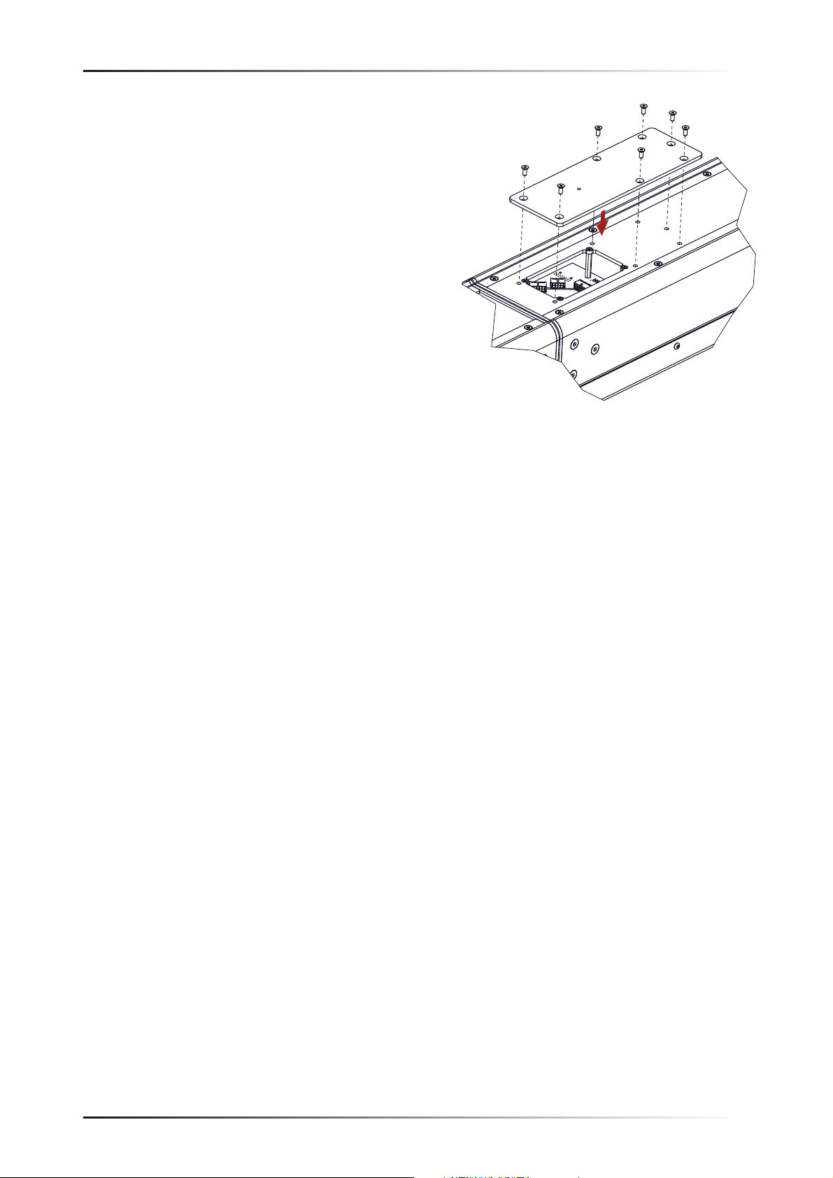
13. Place the sealing plate.
14. Tighten the M4x10 screws using
an IH2.5 hexagon socket
wrench.
© KLING & FREITAG GMBH Version 1.1 Page 23 of 40
Page 24

User's Manual
WARNUNG
VIDA M1.119.08.201908/19/2019
K&F VIDAM
5 Wiring
Wire the speaker as described below.
5.1 Terminal positions and purpose
[A] Netzanschluss, 100 V bis 240 V
AC
[B] Fuse (250 V, 8 A, slow blow)
[C] Sealing power-cable gland and
strain relief
[D] Dante/remote secondary (RJ45)
[E] Dante/remote primary (RJ45)
[F] Audio terminals
inputs: analog, AES 3, output
(AUX): analog (LINE OUT)
[G] GPIO terminals
5.2 Kardioid
5.2.1 AC power inlet
Risk of electric shock
The system must be connected to the mains by a qualified electrician only.
[A] PE conductor
[B] N conductor (neutral)
[C] L conductor (phase)
Cable specification
Rating (min.) Min. outer diameter (strain re-
lief)
Max. outer diameter (strain re-
lief)
8 A 4 mm 10 mm
Page 24 of 40 Version 1.1 © KLING & FREITAG GMBH
Page 25

User's Manual K&F VIDAM
HINWEIS
5.2.2 Audio terminals
Potentially missing contact
Strip the cables by 7 mm.
Aux out (analog):
[A] GND (ground)
[B] COLD (–)
[C] HOT (+)
AES/EBU in (digital):
[D] GND (ground)
[E] COLD (–)
[F] HOT (+)
Analog in:
[G] GND (ground)
[H] COLD (–)
[I] HOT (+)
Cable specification
Conductor type Cross-sectional
area (max.)
Rigid/flexible 0.14 mm² 0.5 mm²
Flexible with wire end ferrule (no plastic ferrule) 0.25 mm² 0.34 mm²
Flexible with wire end ferrule (no plastic ferrule) 0.14 mm² 0.25 mm²
AWG specification 26 62
Cross-sectional
area (max.)
© KLING & FREITAG GMBH Version 1.1 Page 25 of 40
Page 26

User's Manual
HINWEIS
VIDA M1.119.08.201908/19/2019
K&F VIDAM
5.2.3 GPIO
Potentially missing contact
Strip the cables by 7 mm.
[A] to [C] GPO 1:
NC1, M1, NO1:
Status output (warnings, errors)
[D] to [F] GPO 2:
NC2, M2, NO2:
Status output (warnings, errors)
[G] to [I] ALARM:
COM, MUTE, PRIO:
GPIs, for example, for warning systems: auto switch-off for prioritizing
another warning system, or for loading a specific warning-system preset
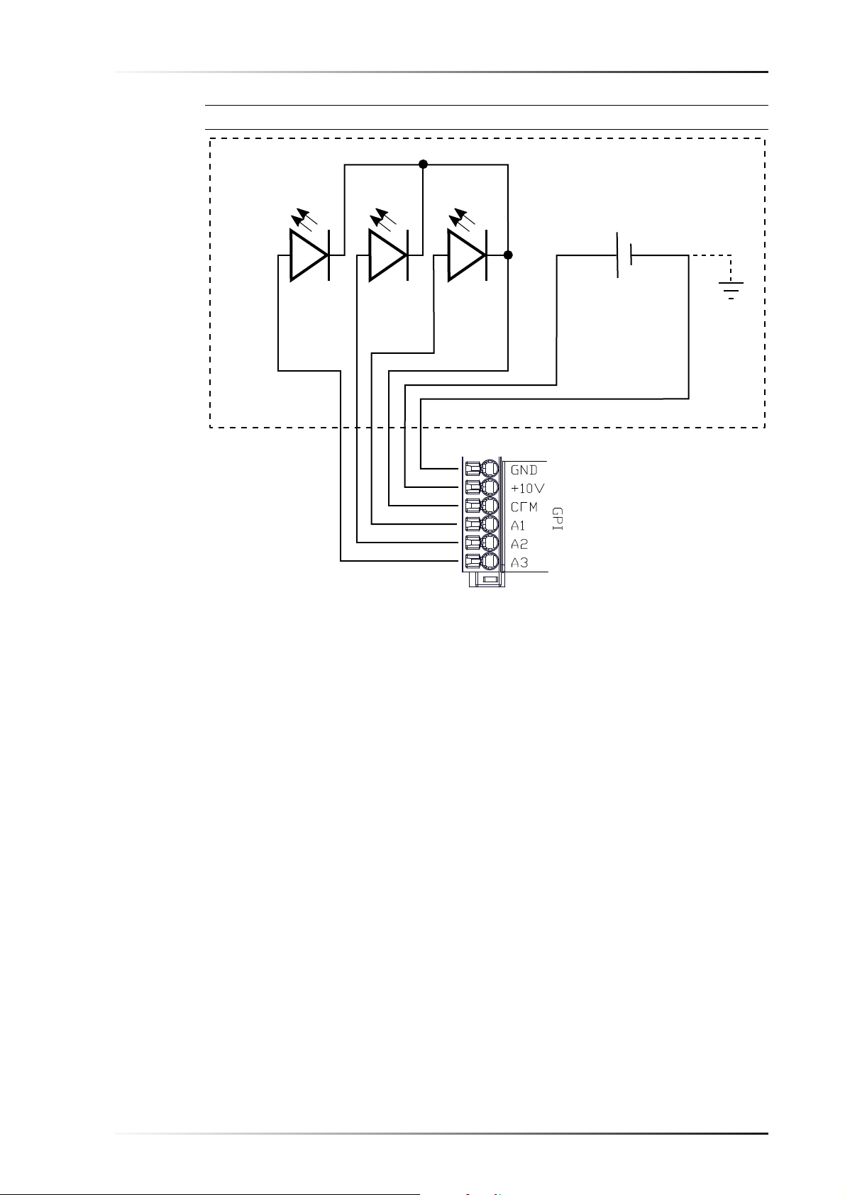
[J] to [O] GPI:
GND, +10 V, COM, A1, A2, A3:
GPIs featuring power sources, allowing for switching between 8 presets
Refer to the VIDA App User’s Guide
for details on the GPIOs.
Cable specification
Conductor type Cross-sectional
area (max.)
Cross-sectional
area (max.)
Rigid/flexible 0.14 mm² 0.5 mm²
Flexible with wire end ferrule (no plastic ferrule) 0.25 mm² 0.34 mm²
Flexible with wire end ferrule (no plastic ferrule) 0.14 mm² 0.25 mm²
AWG specification 26 62
Page 26 of 40 Version 1.1 © KLING & FREITAG GMBH
Page 27

User's Manual K&F VIDAM
6 GPIO specifications
6.1 GPI
GPI A1 – A3:
Type
Power consumption
Internal voltage supply
a)
Floating optocoupler inputs
2.5 mA @10 V
12 V/1 mA, floating
Reverse voltage
HIGH switching threshold
LOW switching threshold
a) If galvanic isolation is required, be sure to use an external voltage source!
Edge-triggered: 5 V (min.) – 30 V (max.)
Edge-triggered: –6 V (min.) – 1.5 V (max.)
GPI prio / mute:
Type
Power consumption
Internal voltage supply
a)
Floating optocoupler inputs
2.5 mA @10 V
12 V/1 mA, floating
Reverse voltage
HIGH switching threshold
Voltage controlled: 5 V (min.) – 30 V (max.)
–6 V
–6 V
LOW switching threshold
GPI PRIO function
Voltage controlled: –6 V (min.) – 1.5 V (max.)
Input selection
GPI MUTE function
a) If galvanic isolation is required, be sure to use an external voltage source!
Mute
© KLING & FREITAG GMBH Version 1.1 Page 27 of 40
Page 28
User's Manual
COM
GPI A1
GPI A2GPI A3 GND10 V
OPT1OPT2OPT3
VIDA M1.119.08.201908/19/2019
K&F VIDAM
6.1.1 GPI internal wiring:
Page 28 of 40 Version 1.1 © KLING & FREITAG GMBH
Page 29

User's Manual K&F VIDAM
GPO 1 / GPO 2 = HIGH
M1 / M2
COMMON
NO1 / NO2
NO = Normally Open
NC1 / NC2
NC = Normally Closed
NC1 / NC2
NC = Normally Closed
NO1 / NO2
NO = Normally Open
M1 / M2
COMMON
GPO 1 / GPO 2 = LOW
6.2 GPO
Type
Max. Continuous current
Max. Peak current
Max. Peak voltage
NO1 / NO2
NC1 / NC2
M1 / M2
GPO internal wiring:
Floating MOFSET switches
0.5 A
1.5 A
60 VAC
Normally open, low impedance to COMMON
Normally closed, high impedance to COMMON
COMMON
•
GPO 1 / GPO 2 is high, status is OK
•
NO1 / NO2 is low-impedance to
COMMON
•
GPO 1 / GPO 2 is low, status is ERROR
•
NO1 / NO2 is high-impedance to
COMMON
© KLING & FREITAG GMBH Version 1.1 Page 29 of 40
Page 30

User's Manual
VIDA M1.119.08.201908/19/2019
K&F VIDAM
7Systemlatency
The following table lists the systems latency that is to be expected of the VIDA M. These values
are true for the firmware version 1.1.0 and without using beamsteering.
Input K&F VIDA M AUX OUT
Analog 6.016 ms 1.260 ms
AES 44.1 kHz 8.299 ms 3.537 ms
AES 48.1 kHz 8.062 ms 3.313 ms
AES 88.2 kHz 7.302 ms 2.540 ms
AES 96 kHz 7.208 ms 2.448 ms
AES 176.4 kHz 6.830 ms 2.046 ms
AES 192 kHz 6.760 ms 2.000 ms
DANTE n.a. n.a.
When using system amplifiers such as the K&F PLM+ series with the AUX OUT, additional delay
will be added due to the amps signal processing. For this reason, the AUX OUT has the least
amount of delay possible, which leaves room to be adjusted via the VIDA APP.
7.1 Dante latency
The latency for the DANTE playback results from the setup for the DANTE network and the
7.1.1 Example
DANTE controller setup: latency = 0.5 ms, sample rate = 96 kHz
Total latency = 7.208 ms (AES 96 kHz) + 0.5 ms (DANTE) = 7.708 ms
By factory default, the two network ports of the VIDAM are configured for redundant operation. This way, you can route a signal through Dante and two separate cable runs in order to
increase fail-safety.
If necessary, you can change the two ports to the ‘Switched’ mode using the Dante Controller
software. This way, you can route control data and the Dante signal from one speaker to the
next. (This is referred to as daisy-chaining.) In this case, you cannot achieve a redundant configuration.
Page 30 of 40 Version 1.1 © KLING & FREITAG GMBH
Page 31

User's Manual K&F VIDAM
7.1.2 Changing between Dante redundancy operating modes
1. Launch Dante Controller.
2. Double-click the VIDAM to be configured to access the Device View.
3. Click the Network Config tab.
4. Make the appropriate settings in the Dante Redundancy section.
7.1.3 Setting up Dante latency with an additional hop
There is one additional network switch installed inside K&F VIDAM which translates to one
additional hop for the network. Be sure to note this when setting up the Dante latency.
For more information about setup and design of a Dante audio network and the necessary
www.audinate.com/resources
© KLING & FREITAG GMBH Version 1.1 Page 31 of 40
Page 32

User's Manual
VIDA M1.119.08.201908/19/2019
K&F VIDAM
8 Initial Operation
1. Download the VIDAApp from the Microsoft Store and install it.
For this purpose, visit the Microsoft App Store and search for VIDA App.
2. Download the VIDAApp User’s Guide from our website (www.kling-freitag.de).
3. Wire the speaker as previously described. See chapter »Wiring« on page 24.
4. Connect the power supply.
5. Add the speakers to your network.
6. Run the VIDAApp on your computer. At program launch, the Setup screen will be displayed.
•
By default, the Offline Device is always displayed at the top left corner. Using that device, you can configure settings without physically connecting a speaker. This means
you can create and store “virtual setups” that you can later apply onto your physical
speakers. To configure Offline Devices, press the button on the right-hand side to
select the desired speaker type and number.
•
The Offline Device will list all accessible VIDA speakers and arrays.
•
While the VIDAApp is uploading the settings to the speakers found, green progress
bars will show the upload status for each system.
•
At first use, a red dot appears next to the speaker. In addition, the front LED will light
red. This means that no valid preset could be uploaded, so the speaker is not ready for
operation.
•
In this case, change to the Beam tab.
•
Press the Presets button in the bottom right corner.
•
Load a setup.
If you just want to perform a function check, the Default setup will do. Note that this
preset is for performing function checks only—it is not suitable for sound adjustment.
Page 32 of 40 Version 1.1 © KLING & FREITAG GMBH
Page 33

User's Manual K&F VIDAM
7. To check, change to the Setup tab.
•
When the progress bar is fully displayed and no red dot is shown, the speaker is ready
for operation.
8. For details on speaker configuration and operation, refer to the VIDAApp User's Manual.
9. Output a low-volume signal to the system.
10. Check to see if the desired signals are applied to the intended speakers and make sure
there is no interference.
•
A red progress bar indicates that the speaker has received damaged data packets, or
no data packets at all. In this case, make sure you are within the WLAN service area,
are connected to the correct WLAN, and no other network-related problems exist.
© KLING & FREITAG GMBH Version 1.1 Page 33 of 40
Page 34

User's Manual
VIDA M1.119.08.201908/19/2019
K&F VIDAM
9 Updates
9.1 Firmware Update
1. Connect the speakers to the mains.
2. Add the speakers to your network.
3. Download the VIDA Firmware Updater from our website (www.kling-freitag.de).
4. Unzip the file and run the executable.
5. Wait a moment until the software has found the speakers on the network and has selected
the current firmware on the K&F server.
6. Compare the version numbers of the current firmware (“Build Info”) on the server with
the installed speaker firmware.
7. If the firmware version installed on the speaker is lower than the version number on the
K&F server, perform a firmware update.
8. Follow the instructions in the Quick Start Guide included in the ZIP file of the VIDA Firmware Updater.
Page 34 of 40 Version 1.1 © KLING & FREITAG GMBH
Page 35

User's Manual K&F VIDAM
9.2 Dante Update
1. Connect the speakers to the mains.
2. Add the speakers to your network.
3. If the Dante Controller application is already installed, proceed to step 10.
4. Visit https://www.audinate.com/products/software/dante-controller.
5. Select your operating system.
6. Click the Dante Controller v… button.
7. Select I need to create an account to create a new account, or click I have an account
to log in using your existing credentials.
8. Click Downloadfile: Dante Controller-….exe and save the file.
9. Launch the saved executable and follow the installation instructions.
10. Run the Dante Controller program.
11. To launch the Dante updater, click the button.
OR: Select View > Dante Updater or press CTRL+U.
12. Open the UPDATES AVAILABLE menu.
13. Select the checkboxes of those speakers you want to update.
14. Click UPDATE SELECTED DEVICES.
15. Select the checkbox to confirm that you understand that audio will be interrupted during
the update process.
16. Click UPDATE NOW.
© KLING & FREITAG GMBH Version 1.1 Page 35 of 40
Page 36

User's Manual
VIDA M1.119.08.201908/19/2019
K&F VIDAM
When the update is complete, the following dialog will be shown:
17. Check the REBOOT REQUIRED box.
Click the REBOOT SELECTED DEVICES button to reboot the updated speaker(s).
10 Care and Maintenance
The K&F VIDAM system can exhibit signs of wear over the years, for example, from mechanical strain, transport damage, corrosion, or improper handling. Signs of wear typically indicate
an increased safety risk.
In general, check the speaker and accessories for signs of wear at regular intervals.
When performing those checks, particularly look for deformations, cracks, dents, damage to
threads, and corrosion. Also check slings and lifts (e.g. shackles, chains, and steel ropes) carefully for wear and deformation.
If as a result of these checks any uncertainty should arise with regard to safety or defects are
found, don’t use the speaker any longer. Contact your retailer.
Inspection regulations may vary depending on application and country of use. Observe all applicable regulations; If in doubt, contact local authorities.
Many countries require regular inspection of mounting components and accessories. An additional annual inspection is typically required to be performed by a technical expert. Moreover,
a legally certified or official authority must perform a detailed inspection every four years.
Therefore, be sure to maintain an inspection log. Enter the values determined for each speaker
and accessory during the periodic checks into this log. This way, relevant data are always at
hand in case of inspection. This inspection log book shall be updated with the inspection steps,
test intervals and parts lists.
Page 36 of 40 Version 1.1 © KLING & FREITAG GMBH
Page 37

User's Manual K&F VIDAM
11 Transportation and Storage
Store the product in a dry place. Also, transport under dry conditions only.
During prolonged storage, ensure sufficient ventilation.
Avoid vibrations during transport.
Avoid mechanical stress during transport and storage, so the product is not damaged.
12 Disposal
This symbol on the electronic equipment indicates that the product must not be disposed of with household waste.
12.1 Germany
Don’t dispose of waste electrical equipment through household waste. All KLING & FREITAG
products are plain business-to-business (B2B) products. <b>Don’t deliver it to official recycling
points either.</b>
KLING & FREITAG GmbH is exclusively responsible for disposing of all KLING & FREITAG waste
equipment marked with a crossed-out garbage-can icon. Please call the below phone number
when you have a KLING & FREITAG product for disposal. We will offer you a straightforward
and professional disposal at no cost.
For further disposal information of KLING & FREITAG waste products, call +49 511 -96 99 7 -0
The WEEE registration number of KLING & FREITAG GmbH is: DE64110372.
12.2 EU, Norway, Iceland, and Liechtenstein
The local distributor (sales partner) in the respective country is responsible for complying with
the national implementation of the WEEE directive.
Contact your retailer or the local authorities for information on the regulations applicable in
any EU member state (except Germany).
12.3 All Other Countries
Contact your retailer or the local authorities for information on the regulations applicable in
any country not listed above.
© KLING & FREITAG GMBH Version 1.1 Page 37 of 40
Page 38

User's Manual
VIDA M1.119.08.201908/19/2019
K&F VIDAM
13 EC Declaration of Conformity
Page 38 of 40 Version 1.1 © KLING & FREITAG GMBH
Page 39

User's Manual K&F VIDAM
© KLING & FREITAG GMBH Version 1.1 Page 39 of 40
Page 40

40
THANK
YOU FOR
CHOOSING
K&F.
KLING & FREITAG GmbH
Junkersstrasse 14 · D-30179 Hannover
Phone +49 (0)511 969970
www.kling-freitag.de · info@kling-freitag.de
 Loading...