

Page 1
K&F VIDA L and VIDA C
Important Information,
Please Read Before Use!
KLING & FREITAG GmbH
Junkersstraße 14
D-30179 Hannover
TEL +49 (0) 511 96 99 70
FAX +49 (0) 511 67 37 94
www.kling-freitag.de
Operating Instructions
Translation of the original instructions
Version 1.3
Released: 28.10.2016
Page 2

Page 3

Operating Instructions K&F VIDA L and VIDA C
KLING & FREITAG GMBH © 2016 Version 1.3 Page 3 of 60
Table of contents
1
Introduction 5
1.1 Icons Used 5
1.2 About these operating instructions 5
2
Product Description 6
2.1 Items IncludedVIDA L 6
2.2 Items IncludedVIDA C 6
2.3 Overview of VIDA L Parts 7
2.3.1 Upper Terminal 8
2.3.2 Lower Terminal 9
2.4 Product Labels and Icons 9
2.4.1 VIDA L name plate 9
2.4.2 VIDA L, bottom label 10
2.4.3 VIDA C name plate 10
3
Intended Use 11
4
System Requirements 11
5
Safety Instructions 12
5.1 General Safety Instructions 12
5.2 Preventing Hearing Damage 13
6
VIDA L Setup 13
6.1 Required Tools 13
6.2 Interconnecting System Components 13
6.2.1 Troubleshooting Mechanical Issues 18
6.2.2 Setting up a Speaker Array 18
6.2.3 Mounting the VIDA C 20
7
Dismounting 23
8
Wiring 23
8.1 AMP OUT pinout 24
8.2 Wiring Instructions 25
8.3 Connecting the VIDA L Speakers 26
8.4 Status indicator 29
9
First-time Use 30
9.1 Reset dongle 30
10
VIDA App Quick Overview 32
10.1 Initial Function Checks 32
10.2 Key Settings on the Setup Screen 33
10.3 Key Settings on the Beam Screen 33
10.4 Key Settings on the Audio Tools Screen 33
Page 4

Operating Instructions K&F VIDA L and VIDA C
KLING & FREITAG GMBH © 2016 Version 1.3 Page 4 of 60
10.5 Key Settings on the Groups Screen 33
10.6 Key Information on the Status Screen 33
11
Control 35
11.1 Control inputs (GPI) 35
11.1.1 GPI Hardware 35
11.1.2 GPI Software 35
11.2 GPO Control Outputs 37
11.2.1 GPO Hardware 37
11.2.2 not_found 37
11.3 Software GPI 38
12
Updating the Firmware 39
13
Transportation and Storage 43
14
Care and Maintenance 43
15
Technical Specifications 44
15.1 Technical Specifications VIDA L 44
15.2 Technical Specifications VIDA C 45
16
Measuring Diagrams 46
16.1 VIDA L diagrams 46
17
Dimensions and Weight 50
17.1 VIDA L, Dimensions and Weight 50
17.2 VIDA L with VIDA C, Dimension and Weight 51
17.3 VIDA L Mass Center 52
18
Accessories 53
18.1 Accessories for VIDA L 53
18.2 Accessories for VIDA L Flying Frame 55
19
Disposal 56
19.1 Germany 56
19.2 EU, Norway, Iceland, and Liechtenstein 56
19.3 All Other Countries 56
20
Declaration of Conformity (CE) 58
Page 5
Operating Instructions K&F VIDA L and VIDA C
KLING & FREITAG GMBH © 2016 Version 1.3 Page 5 of 60
1. Introduction
Thank you for purchasing a KLING & FREITAG product. You have acquired a quality VIDA L
speaker system with built-in power amplifier designed for maximum performance. To
guarantee trouble-free operation and enable the device to achieve its full potential, please
read these operating instructions carefully before use. You will find that your VIDA L speaker
system is truly a versatile pro-grade tool.
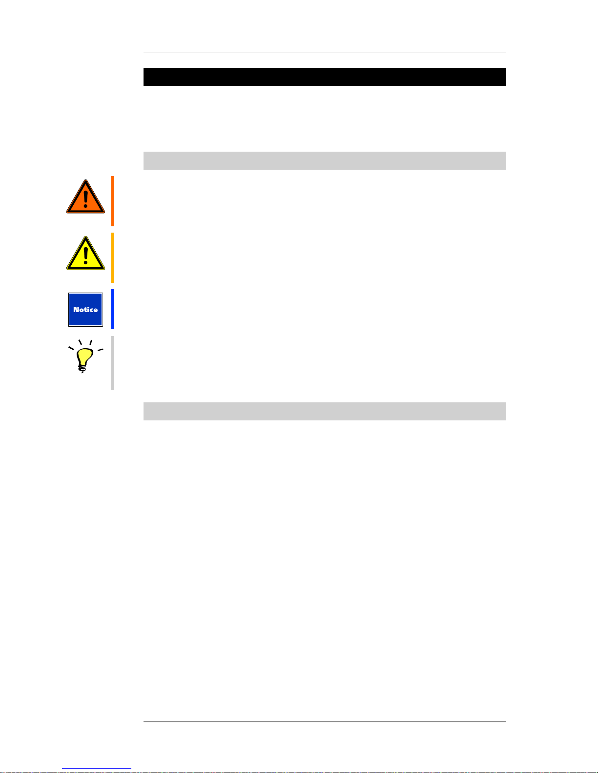
1.1 Icons Used
Warning
This icon indicates a risk of injury or death. Not following these instructions may result in
serious health problems including potentially fatal injuries.
Caution
This icon indicates a possibly dangerous situation. Not following these instructions may cause
minor injuries or damage.
This icon marks instructions for proper use of the described products. Not following these
instructions may cause malfunctions or damage.
Tip
This icon marks information provided for simplified use of the described products.
1.2 About these operating instructions
© KLING & FREITAG GMBH. All rights reserved.
All specifications regarding the features of the described products and applicable safety
guidelines provided in these operating instructions are based on information available at the
time of publishing.
We assume no responsibility for technical specifications, dimensions, weights, and properties.
All information in these operating instructions is subject to change without notice.
To ensure safe operation, all persons using the speaker system must have access to these
operating instructions and all other relevant material during installation. Don’t set up
or operate the speaker system before you have carefully read and fully understood this
operating instructions. Keep the operating instructions readily available on site at all times.
The original language of all KLING & FREITAG operating instructions is German.
If you need operating instructions from KLING & FREITAG, you can order a replacement or
download it from our www.kling-freitag.de.
Contact: info@kling-freitag.de
KLING & FREITAG GMBH, Junkersstr. 14, D-30179 Hannover
Telefon +49 (0) 511 96 99 70, Telefax +49 (0) 511 67 37 94
Page 6

Operating Instructions K&F VIDA L and VIDA C
KLING & FREITAG GMBH © 2016 Version 1.3 Page 6 of 60
2. Product Description
2.1 Items IncludedVIDA L
• Line-array speaker with beam steering (1 item) and optional VIDA C
• VIDA L reset dongle (1 item)
• Neutrik PowerCon TRUE1 power cord (with Type C safety plug)
Or Neutrik PowerCon TRUE1 power cord (1 item, no connector, for 115 V operation)
• (1x) Operating Instructions
Using the VIDA App software is obligatory for setting up the system. You can download the
latest version from the Microsoft App Store (http://www.microsoftstore.com).
http://www.microsoftstore.com
When setup is complete, if you use the speaker in a fixed installation, you will not need VIDA
App anymore.
2.2 Items IncludedVIDA C
• (1x) VIDA C
• (1x) Allen wrench (6 mm)
• NLT-425 speaker patch cord, 0.5 m, K&F item #35891 (1 item)
• (1x) Operating Instructions
Page 7
Operating Instructions K&F VIDA L and VIDA C
KLING & FREITAG GMBH © 2016 Version 1.3 Page 7 of 60
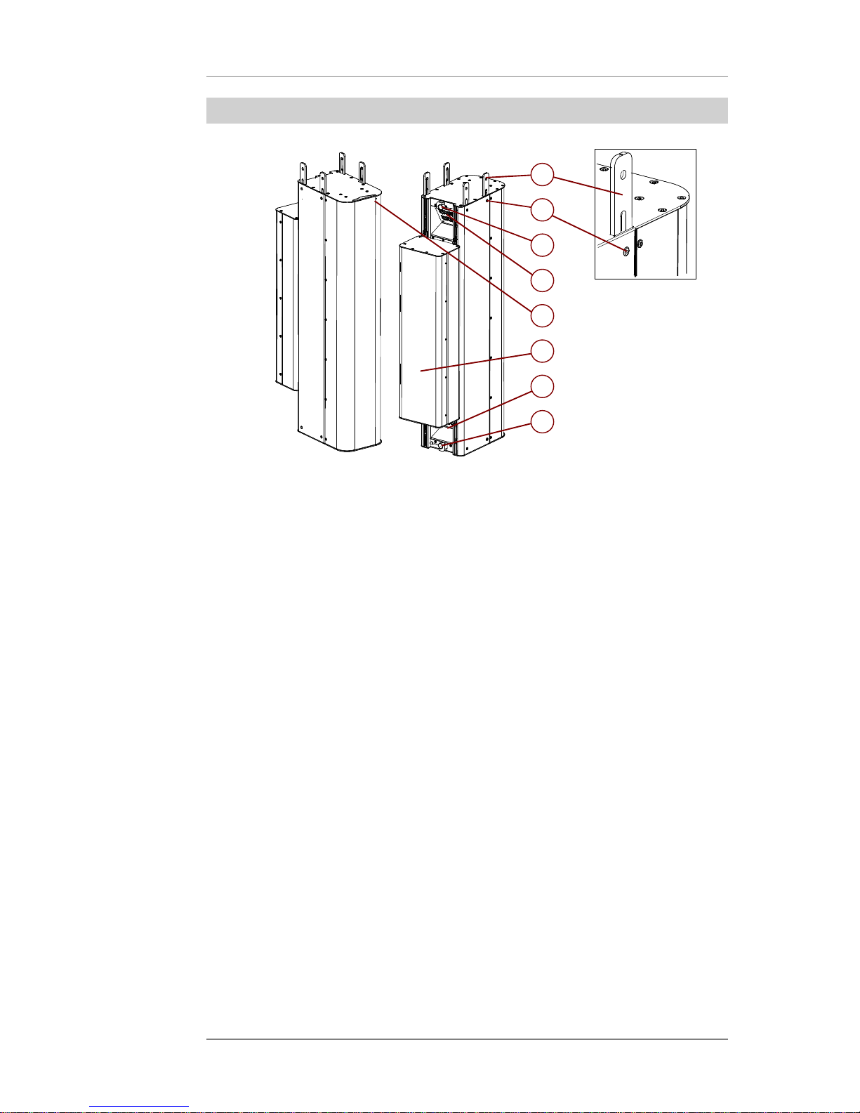
2.3 Overview of VIDA L Parts
3
4
5
6
7
8
1
2
1. (4x) Connecting Adapters (extended)
2. (8x) Connecting Pins
3. Upper Lever
4. Upper Terminal
5. Status indicator
6. 'VIDA C' (optional)
7. Lower Terminal
8. Bottom Lever
Page 8
Operating Instructions K&F VIDA L and VIDA C
KLING & FREITAG GMBH © 2016 Version 1.3 Page 8 of 60
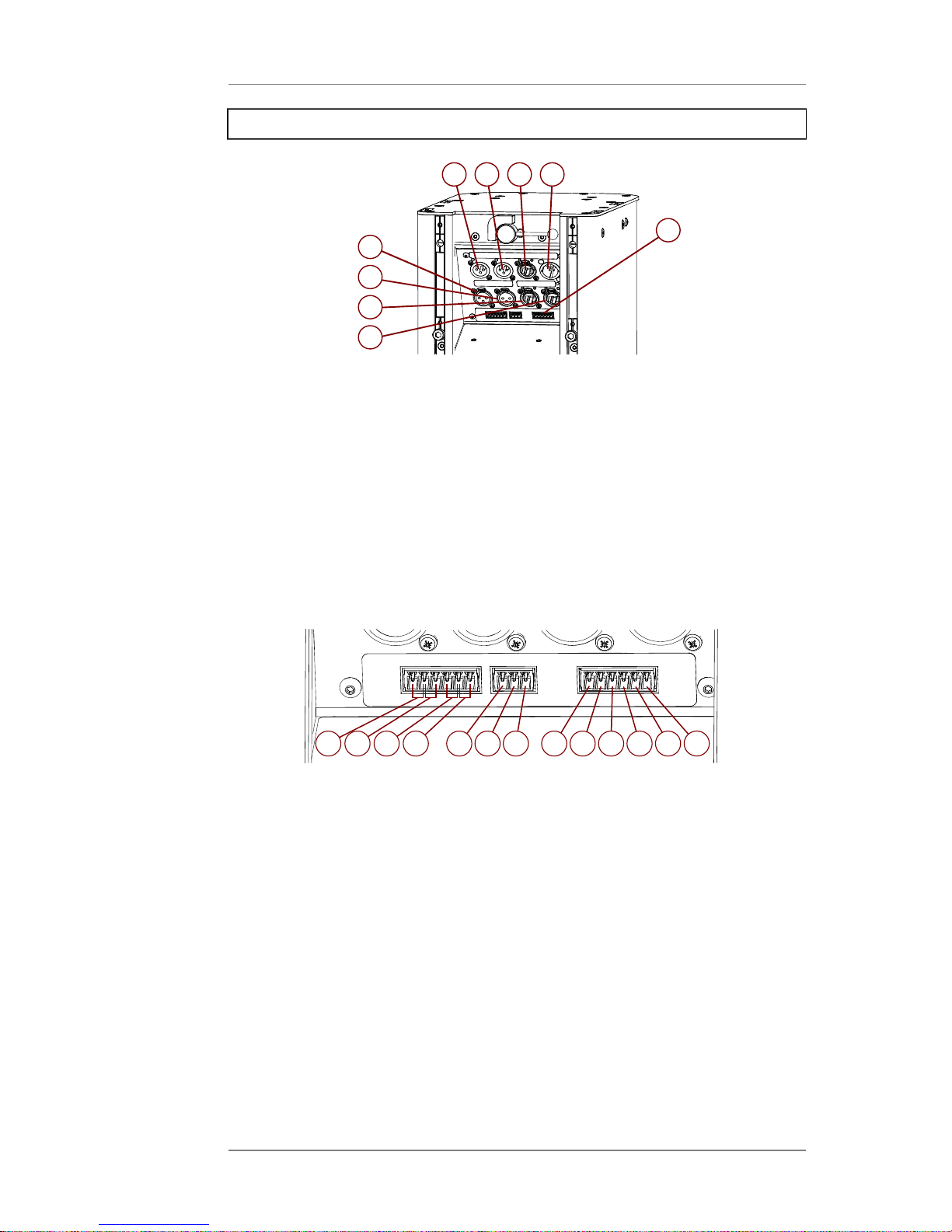
2.3.1 Upper Terminal
1
2
3
4
5
6
8
7
9
1. Analogue Input (XLR)
2. AES/EBU Input (XLR)
3. VIDA Link Bus Input (RJ45)
4. AC Mains, 100 V - 240 V AC (Neutrik PowerCon True1)
5. Analogue Link (XLR)
6. AES/EBU Link (XLR)
7. Dante/Remote Primary (RJ45)
8. Dante/Remote Secondary (RJ45)
9. Phoenix Connectors (see below)
1
2
3
4
5
687
9
10
11
12
13
• 1. – 4. NC1, NO1, NC2, NO2: GPOs used for status output (warnings, errors)
• 5. – 7. COM, MUTE, PRIO: GPIs used, for example, for warning systems: auto switch-off
for prioritizing another warning system, or for loading a specific warning-system preset
• 8. – 13. GND, +10 V, COM, a1, a2, a3: GPIs featuring power sources, allowing for
switching between 8 presets
Page 9
Operating Instructions K&F VIDA L and VIDA C
KLING & FREITAG GMBH © 2016 Version 1.3 Page 9 of 60
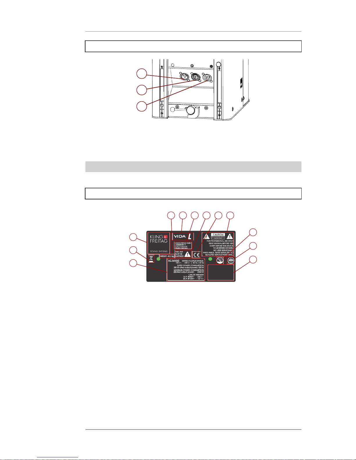
2.3.2 Lower Terminal
1
2
3
1. AUX output (XLR)
2. VIDA Link Bus Output (RJ45)
3. AMP output (Neutrik Speakon)
2.4 Product Labels and Icons
VIDA L speakers have one or more labels showing icons and important information.
2.4.1 VIDA L name plate
4
5
6
7
8
9
10
11
1
2
3
12
1. Manufacturer logo
2. Disposal information (see the Disposal chapter on page 56)
3. Rating information (see the Wiring chapter on page 23)
4. Product weight
5. Product name
6. Manufacturer address
7. Grounding instruction
8. CE mark
9. Warnings
10. NEVER use this product in tropical climates or under similar climate conditions.
11. Never use this product in places exceeding an altitude of 2000 meters.
12. Serial number, weight
Page 10
Operating Instructions K&F VIDA L and VIDA C
KLING & FREITAG GMBH © 2016 Version 1.3 Page 10 of 60
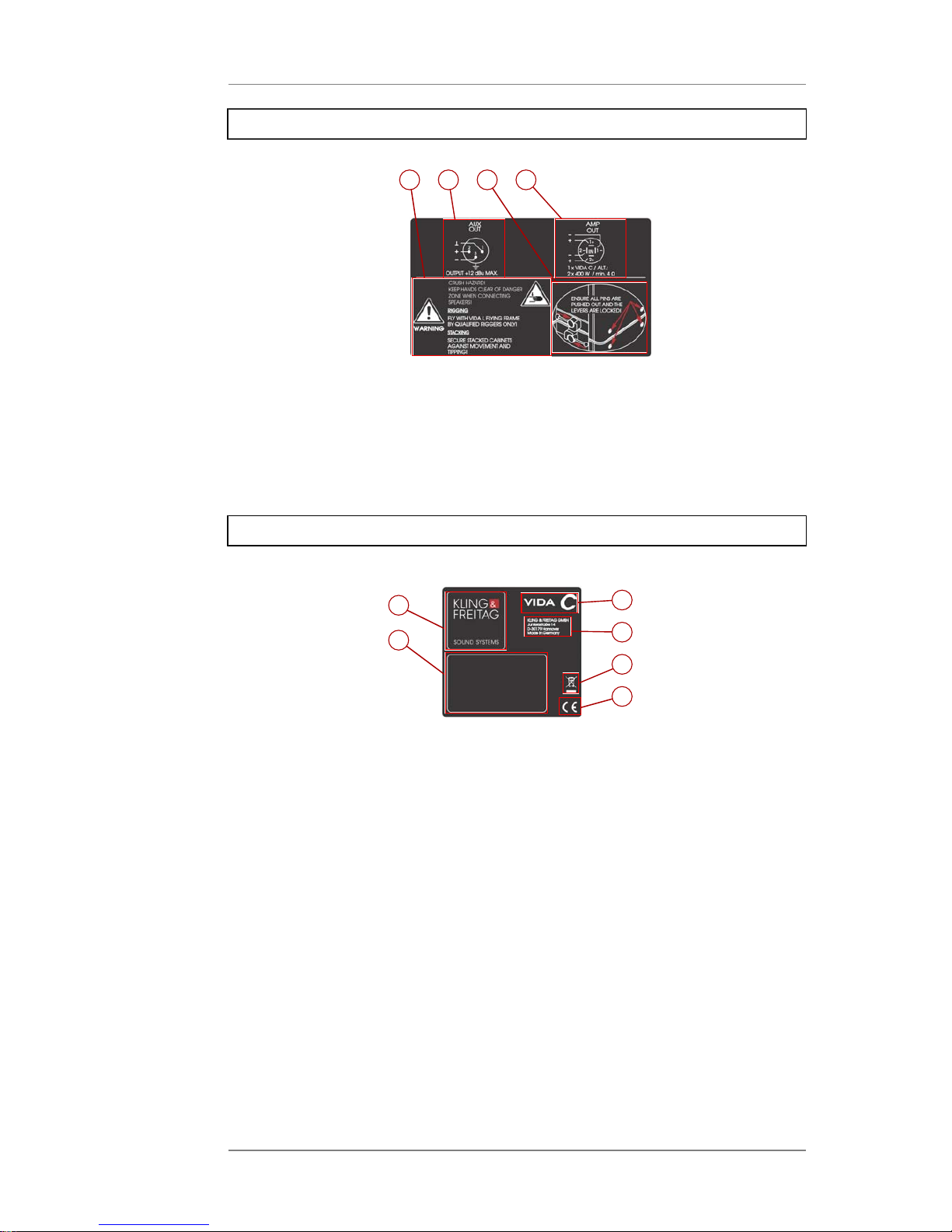
2.4.2 VIDA L, bottom label
1
2
3
4
1. Warnings
2. AUX-out pinout and internal wiring (see the Wiring chapter on page 23)
3. AMP-out pinout and internal wiring (see the Wiring chapter on page 23)
4. Safety instructions on operating rigged speakers (see the Attaching a Flying Frame to a
Speaker chapter on page 13)
2.4.3 VIDA C name plate
4
5
6
1
2
3
1. Manufacturer logo
2. Serial number, weight
3. Product name
4. Manufacturer address
5. Disposal information (see the Disposal chapter on page 56)
6. CE mark
Page 11

Operating Instructions K&F VIDA L and VIDA C
KLING & FREITAG GMBH © 2016 Version 1.3 Page 11 of 60
3. Intended Use
Use the KLING & FREITAG speaker for audio reproduction only. Always use the specified
accessories for flying or rigging.
Never operate the speaker in environments where the temperature exceeds 35 °C / 95 °F.
Never operate the speaker in places exceeding an altitude of 2000 meters / 6000 ft.
Make sure that the humidity is between 10% and 90%.
When using a single flying frame, you can fly up to 8 VIDA L speakers without VIDA L at a
maximum down-tilt of –9.5° or up to 8 VIDA C speakers with VIDA L at a maximum down-tilt
of –7.3°. VIDA C
When using two flying frames, you can fly up to 6 horizontally aligned VIDA L speakers
without VIDA L or up to 5 VIDA C speakers with VIDA L. VIDA C
For commercial use as specified in this document only!
Unless otherwise stated, use only KLING & FREITAG original parts for mounting the speakers.
Never use other parts (in particular, parts not made by KLING & FREITAG).
Any other use not described in this document is not an intended use
4. System Requirements
For operating a VIDA L speaker, you only need a power source and an audio source. For
setup purposes, you need a computer running Windows 8, 8.1, or 10 and the VIDA App
installed.
The VIDA App required for setting up the speaker system is freely available at the Windows
Store.
The software allows for making all required adjustments to the VIDA L: emulating audiences,
managing array groups, making detailed sound-ray settings, and selecting the appropriate
cardioid configuration.
For more information, refer to the VIDA App operating instructions, which is available for
download on our website.
The audio can be applied from any source including Analog, AES, or Dante.
Page 12
Operating Instructions K&F VIDA L and VIDA C
KLING & FREITAG GMBH © 2016 Version 1.3 Page 12 of 60
5. Safety Instructions
5.1 General Safety Instructions
Warning
Power Supply
• Before connecting the device to a power source, check if the local voltage matches the
voltage marked on the device. NEVER connect the device to an unauthorized power
source. Doing so may permanently destroy the device.
• Make sure that the power outlet has a ground connector and it is connected to the
device through the PE conductor of the power cord!
• Always route power cords so that they are protected from damage caused by stepping
on it, tensile stress, or getting caught.
• Make sure you can disconnect the device from the mains at any time!
• All equipment interconnected through signal cables must be connected to common
ground. Failing to do so may result in an electric shock or permanent damage to the
connected equipment.
Warning
I/O
• The device does not include a master fuse. Therefore, be sure to protect the supply line
appropriately (230 V: 16 A fuse max.; 115 V: 20 A fuse max.)!
• Also make sure the supply line has an appropriately dimensioned cable cross-section.
• Always use properly shielded cables with connectors attached as specified by the EMC
directive.
• This device is not designed for home use.
• The device is designed for indoor use only.
Caution
Maintenance and Technical Service
Never perform any maintenance work on the equipment other than what is described in
these operating instructions. Have repairs works performed by a qualified service technician
only.
Only qualified technicians expressly authorized by KLING & FREITAG are permitted to repair
the device. This is required, for example, if
• the power cord or power inlet have been damaged,
• objects or liquids have got inside the device,
• the device was exposed to rain,
• the device doesn't appear to be functioning properly,
• the device has fallen down or the enclosure has been damaged.
Caution
Never place your devices
• where they are permanently exposed to direct sunlight,
• near heat sources or open fire,
• where the airflow for cooling is blocked,
• where they are exposed to high moisture,
• where they are exposed to strong vibrations or dust.
Page 13
Operating Instructions K&F VIDA L and VIDA C
KLING & FREITAG GMBH © 2016 Version 1.3 Page 13 of 60
Caution
Intrusion of liquids
• Make sure at all times that no objects or liquids can intrude or leak into the device.
Noise
RF interference at the power cord or line cables may result in unwanted noise.
When using the AES/EBU input, strong interference may result in a total audio dropout.
Prolonged Periods Of Non-operation
Disconnect the power cord from the mains if you don't use the device for a prolonged period
of time.
Cleaning
Before cleaning, disconnect the device from power. Use a dry cloth only.
Transportation
When transporting the device, make sure that it is protected from vibrations.
5.2 Preventing Hearing Damage
Caution
This equipment is capable of delivering sound pressure levels in excess of 90 dB SPL, which
may cause permanent hearing damage. Keep your distance from operating speakers.
6. VIDA L Setup
6.1 Required Tools
The following is required for mounting the VIDA C to the VIDA L speaker:
• Allen wrench (6 mm)
• Torque wrench for 16Nm
6.2 Interconnecting System Components
The following describes how to interconnect VIDA L system components. The approach
is basically applicable to VIDA L accessories, too. Here, we will explain how to securely
interconnect two speakers as an example. In this case, whether the components are placed
vertically (upright) or horizontally is not important.
The key parts required for interconnecting two components are the upper and lower levers.
Upper lever:
The upper lever is used for locking or unlocking the rigging-system connecting adapter (steps
1 – 6 below).
Lower lever:
The lower lever is used for locking or unlocking the connection to another speaker or
accessory (steps 7 – 9 below).
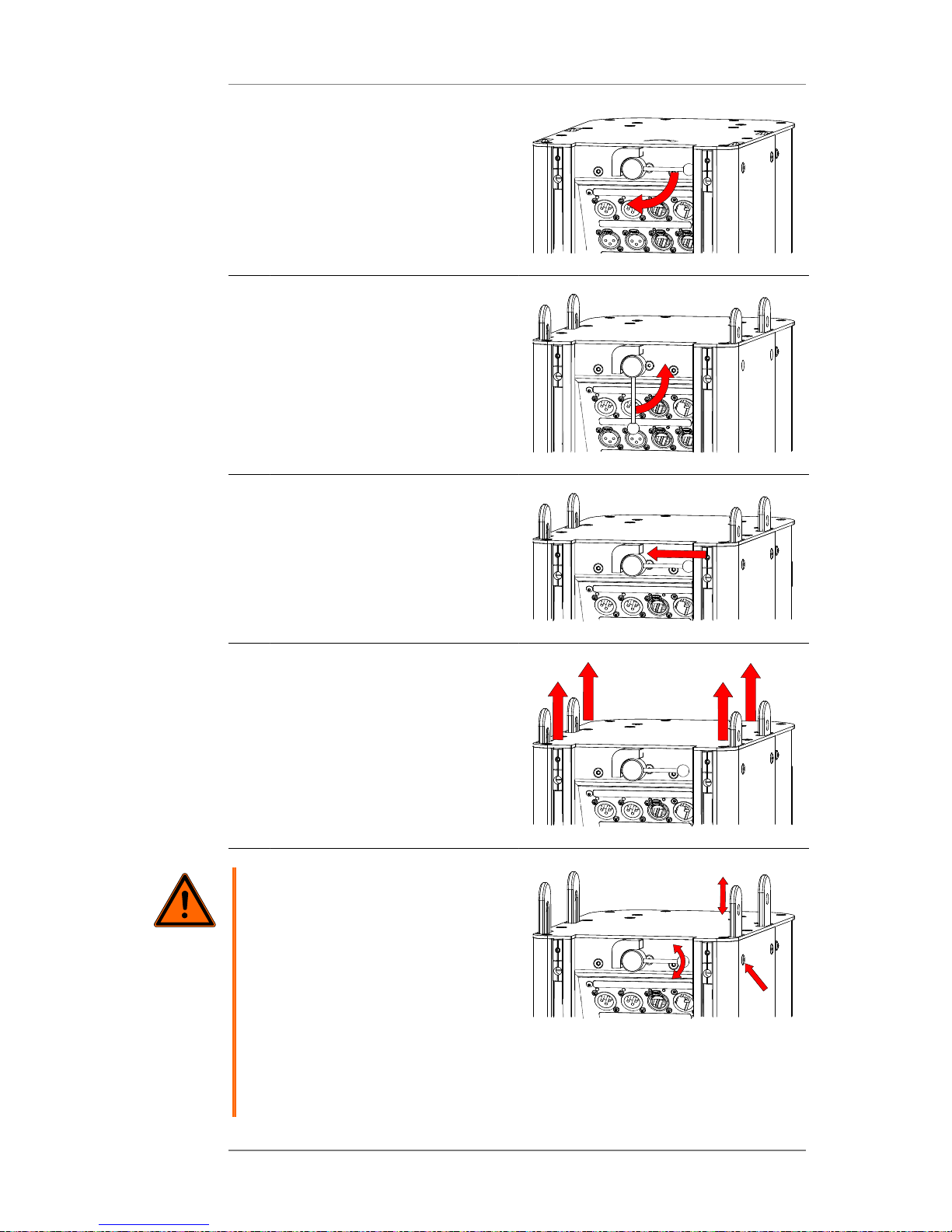
1 Pull out the upper lever towards its
longitudinal axis.
Page 14
Operating Instructions K&F VIDA L and VIDA C
KLING & FREITAG GMBH © 2016 Version 1.3 Page 14 of 60
2. Rotate the lever clockwise by
90 degrees.
Doing so will push the connecting
adapters out of the speaker.
3. When all four connecting adapters
are in position, rotate the lever
anticlockwise back into the vertical
position.
4. Push the lever back in in
longitudinal direction until it snaps.
This will lock the lever.
5. Pull the connecting adapters out of
the housing.
The connecting adapters are
fastened and secured by means of
connecting pins.
6.
Warning
Danger! Risk of injury from
falling objects!
Improperly mounted speakers
are not safe for suspending.
Objects falling down impose a
deadly risk for people standing
near-by!
Check whether all four
connecting adapters have been
fully pushed out and locked (a).
Make sure that the lever has
returned to its captive position
(b).
4x
4x
a
b
c
Page 15
Operating Instructions K&F VIDA L and VIDA C
KLING & FREITAG GMBH © 2016 Version 1.3 Page 15 of 60
On both sides of the speaker,
make sure that you can see
and feel the chamfers of the
4 connecting pins (8 pins in total)
are flush with the walls from
outside (a).
The speaker top with the pulled-out connecting adapters is now ready for interconnection
with another speaker or accessory.
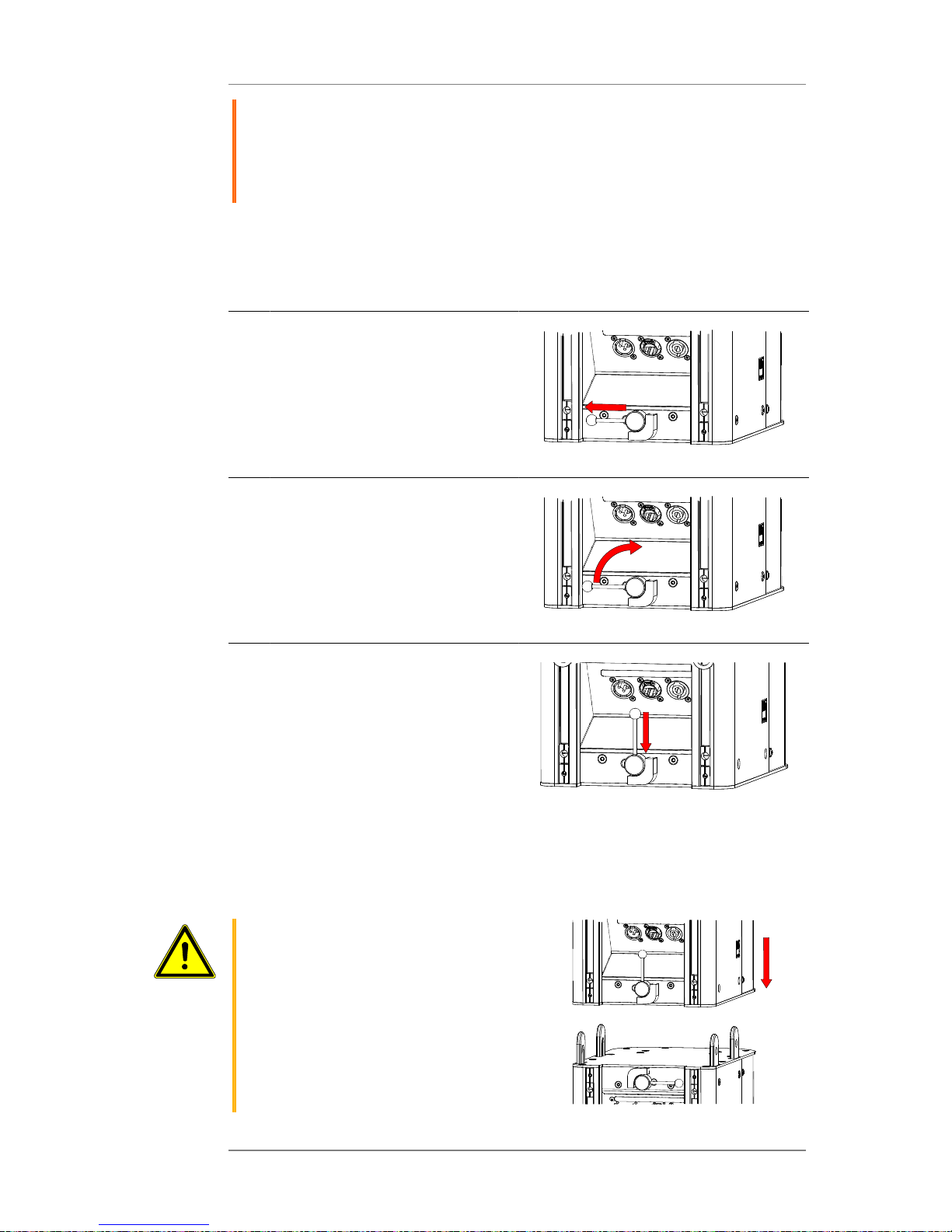
The steps 7 – 9 below show how to prepare the speaker bottom for accepting the connecting
adapters of another speaker or accessory.
7. Pull out the lower lever towards its
longitudinal axis.
8. Rotate the lever clockwise by
90 degrees.
9. Push the lever longitudinally into
the joint case to lock it.
Doing so will allow the receptacles
to accept the connecting adapters
of another speaker or accessory.
This speaker is now ready for accepting and securely locking the connecting adapters of
another speaker or accessory. The steps below explain how to securely mount two prepared
speakers to each other.
10.
Caution
Crushing hazard!
When mounting, avoid crushing
your body parts between system
components moving towards
each other.
While mounting speakers onto
each other, never put your hands
between the connecting faces
(i.e. speaker bottom and top
faces)!
Page 16
Operating Instructions K&F VIDA L and VIDA C
KLING & FREITAG GMBH © 2016 Version 1.3 Page 16 of 60
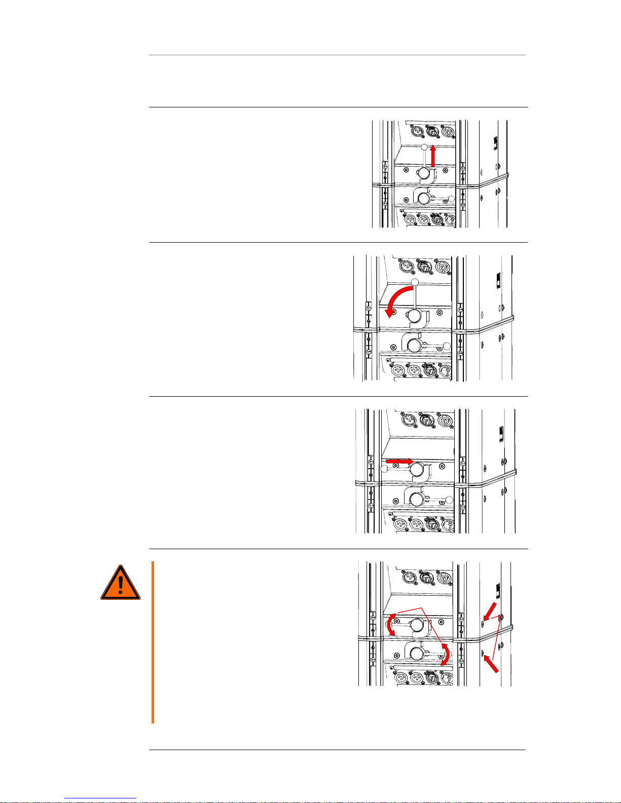
Put this speaker onto another one
or the connecting adapters of an
accessory.
11. Pull out the lower lever towards its
longitudinal axis.
12 Rotate the lever anticlockwise into
its original position.
Doing so will fasten and secure the
connecting adapters of the lower
speaker.
13 Push the lever back in in
longitudinal direction until it snaps.
14
Warning
Danger! Risk of injury from
falling objects!
Improperly mounted speakers
are not safe for suspending.
Objects falling down impose a
deadly risk for people standing
near-by!
Check whether all four
connecting adapters have been
fully pushed out and locked (a).
Make sure that the lever has
returned to its captive position
(b).
4x
b
a
4x
Page 17

Operating Instructions K&F VIDA L and VIDA C
KLING & FREITAG GMBH © 2016 Version 1.3 Page 17 of 60
On both sides of the speaker,
make sure that you can see
and feel the chamfers of the
4 connecting pins (8 pins in total)
are flush with the walls from
outside (a).
Tip
To support the adapters
snapping into each other,
slightly push the joint in every
direction.
If any connecting pin still doesn’t
extend fully, try pulling it
out through the emergency
bore. (See the Troubleshooting
Mechanical Issues chapter on
page 18.)
Page 18
Operating Instructions K&F VIDA L and VIDA C
KLING & FREITAG GMBH © 2016 Version 1.3 Page 18 of 60
6.2.1 Troubleshooting Mechanical Issues
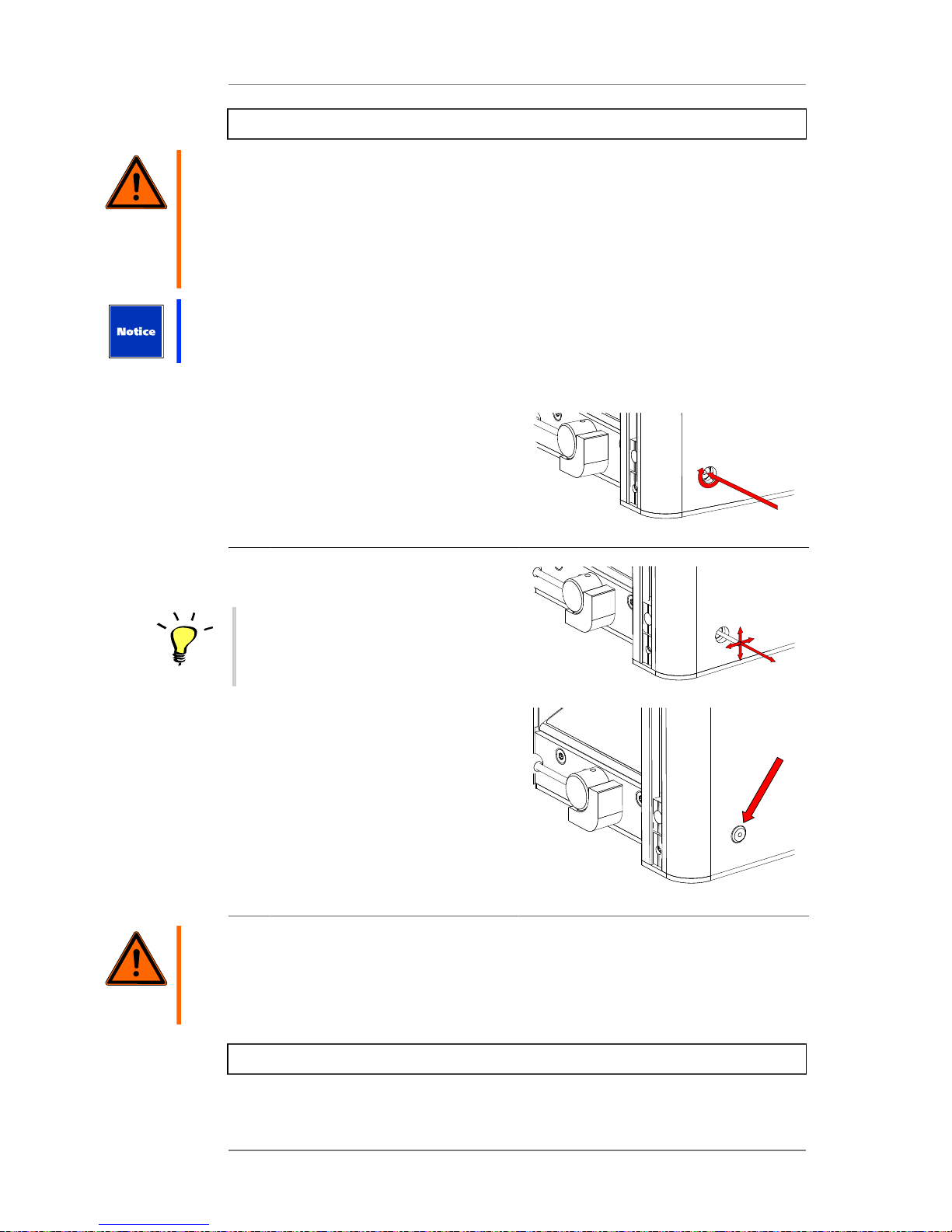
Warning
Danger! Risk of injury from falling objects!
Improperly mounted speakers are not safe for suspending. Objects falling down impose a
deadly risk for people standing near-by!
At the end of the installation process, make sure that the lever locks into its horizontal
position. In this position, the lever is secured against rotation.
Never use the rigging system if the lever does rotate in this position! Contact your retailer.
At the end of the connecting process, if the connecting pins have not been sufficiently
moved out, the rigging system of this speaker may be damaged.
If the pin is blocked by dirt or foreign objects, try loosening it through the emergency bore.
1 For this purpose, carefully thread
an M4 screw into the connecting
pin from outside.
2. Trying moving the screw and the
lever to release the blocked pin.
Tip
If you have successfully released
and pulled out the pin, be sure
to have any issues resolved
before next use.
Warning
Danger! Risk of injury from falling objects!
Improperly mounted speakers are not safe for suspending. Objects falling down impose a
deadly risk for people standing near-by!
Have the flying system repaired by a KLING & FREITAG authorized service provider.
6.2.2 Setting up a Speaker Array
Page 19

Operating Instructions K&F VIDA L and VIDA C
KLING & FREITAG GMBH © 2016 Version 1.3 Page 19 of 60
1 Prepare the interfacing speaker
sides as described on page 13ff.
Upper speaker: steps 1 – 6
Lower speaker: steps 7 – 9
2.
Caution
Crushing hazard!
When mounting, avoid crushing
your body parts between system
components moving towards
each other.
While mounting the speakers
to one another, never put your
hands between the connecting
faces (i.e. speaker bottom and
top faces)!
After preparing the speakers as
explained, push them towards each
other.
Make sure that the four connecting
adapters smoothly slide into the
other speaker’s housing.
3.
Tip
Also note that trouble-free
assembly might be obstructed,
for example, by an uneven
ground surface.
To support the adapters
snapping into each other,
slightly push the joint in every
direction.
If you still have trouble
mounting the speakers, switch to
a more level place.
In entirely level places, if
you cannot achieve secure
interconnection between
speakers, the rigging system of
at least one speaker is probably
faulty. In this case, don’t attach
the faulty speaker to the other
speakers but have it repaired.
4.
Warning
Danger! Risk of injury from
falling objects!
Improperly mounted speakers
are not safe for suspending.
Objects falling down impose a
deadly risk for people standing
near-by!
a
b
Page 20

Operating Instructions K&F VIDA L and VIDA C
KLING & FREITAG GMBH © 2016 Version 1.3 Page 20 of 60
On both sides of each speaker
box, make sure that you can see
and feel the chamfers of the
4 connecting pins (8 pins in total)
are flush with the walls from
outside (a).
Make sure that all levers of both
speakers are locked in their
captive positions (a, 2x).
a
b
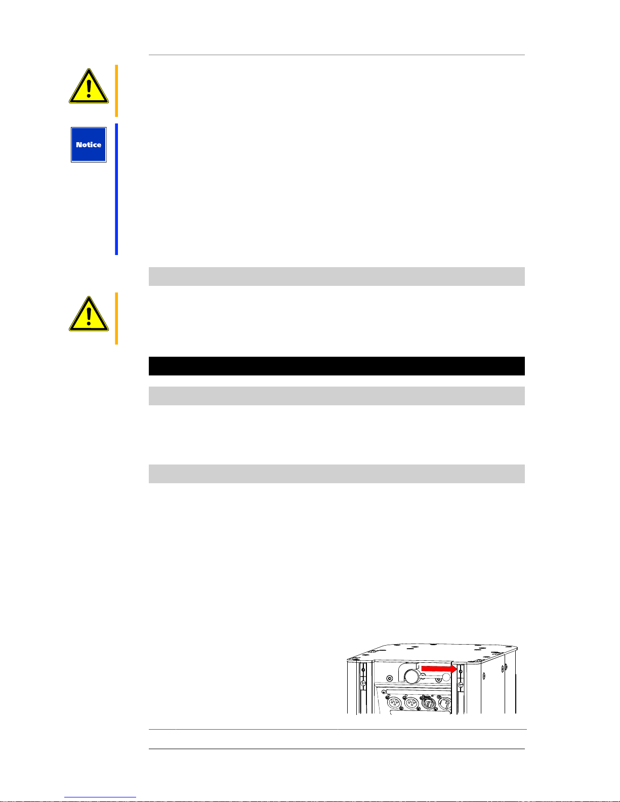
6.2.3 Mounting the VIDA C
Warning
Danger! Risk of injury from falling objects!
Improperly mounted speakers are not safe for suspending. Objects falling down impose a
deadly risk for people standing near-by!
To attach the VIDA C, use only the dedicated fasteners featuring captive screws inside the
rails located at the VIDA L rear panel.
Make sure all bolts and screws are tightened to the specified torque.
Tip
If you want to use the VIDA L speakers in combination with VIDA C, you need to attach one
VIDA L to each VIDA App speaker. You need to emulate that setup using the [$], too.
You can mount a VIDA C to a VIDA L speaker while it is still in the transportation case.
1 Loosen the mounting screws until
the VIDA C can be mounted.
Note that these are captive
mounting screws, i.e. they are tied
to their respective holders. To avoid
damaging the screws and threads,
don’t apply excessive force when
loosening the screws.
Page 21

Operating Instructions K&F VIDA L and VIDA C
KLING & FREITAG GMBH © 2016 Version 1.3 Page 21 of 60
2. Place the VIDA C onto the VIDA L
speaker.
The Speakon port of the VIDA C
needs to point towards the lower
connector panel (three ports).
3. When the VIDA C is properly
aligned to the speaker through
all four screws, push it towards
the lower connector panel until it
stops.
Page 22

Operating Instructions K&F VIDA L and VIDA C
KLING & FREITAG GMBH © 2016 Version 1.3 Page 22 of 60
4. Fasten all four screws finger-tight.
Connect the VIDA C to the VIDA L’s
AMP OUT port using a 4-pin
Speakon patch cord.
Page 23

Operating Instructions K&F VIDA L and VIDA C
KLING & FREITAG GMBH © 2016 Version 1.3 Page 23 of 60
7. Dismounting
Tip
When dismounting is completed, store all speakers and accessories in the transportation case.
This way, they cannot get lost and are always at hand when needed. In addition, the parts
are protected at least temporarily against the effects of unfavorable weather conditions, etc.
Basically, dismounting the speakers is performed in reverse order of the installation process.
• Unload the interconnect point.
• Rotate the lever on the upper speaker clockwise until it snaps.
• Pull the speakers apart.
Tip
If you intend putting the speakers into a transportation case, you don’t need to push the
connecting adapters back into the housing and to unmount the VIDA C. The transportation
case is designed for housing the speaker with the adapters extruded and the VIDA C
mounted. This saves a few steps when dismounting and remounting the speakers.
8. Wiring
Warning
Risk of Electrical Shock
Speaker-signal currents are potentially hazardous to the human body.
When the system is in use, make sure that the connectors are secured against inadvertent
touch.
Be sure to fully insert the stripped wires into the Euroblock, so stripped wire parts cannot be
touched.
Warning
Power Supply
• Make sure that the power outlet has a ground connector and it is connected to the
device through the PE conductor of the power cord!
• Always route power cords so that they are protected from damage caused by stepping
on it, tensile stress, or getting caught.
• Make sure you can disconnect the device from the mains at any time!
• All equipment interconnected through signal cables must be connected to common
ground. Failing to do so may result in an electric shock or permanent damage to the
connected equipment.
Warning
I/O
• The device does not include a master fuse. Therefore, be sure to protect the supply line
appropriately (230 V: 16 A fuse max.; 115 V: 20 A fuse max.)!
• Also make sure the supply line has an appropriately dimensioned cable cross-section.
• Always use properly shielded cables with connectors attached as specified by the EMC
directive.
• This device is not designed for home use.
• The device is designed for indoor use only.
Run the cables in a way that nobody can trip over them.
Never use signal cables or power cords for suspending, aligning, or securing the systems.
Page 24

Operating Instructions K&F VIDA L and VIDA C
KLING & FREITAG GMBH © 2016 Version 1.3 Page 24 of 60
Warning
Tip
When connecting more than one speaker, we recommend using a split adapter.
8.1 AMP OUT pinout
1
-
2
-
1+
2+
OUT
CH1-
CH1+
(> 4 Ohm)
}
CH2-
CH2+
(> 4 Ohm)
}
Pinout:
CH1 = 1+ / 1CH 2 = 2+ / 2-
Power:
400 W rms/800 W peak, min. 4 Ohm
Never bridge the 2 AMP OUT channels of the VIDA L.
This output is provided mainly for connecting a VIDA C; However, using the VIDA App, you
can set up the VIDA L speaker for joint operation with PASSIO SUB 12 or PASSIO SUB 15. In
addition, using the Flat setting, you can connect a passively equalized head.
There are 2 amplifier channels using the same signal. If you need to connect more than
2 PASSIO SUB units, you can run 2 units on each channel using a splitter cable.
Using the app, you can configure the Gain and Delay parameters of the AMP OUT. For more
information, refer to the VIDA App operating instructions.
Page 25

Operating Instructions K&F VIDA L and VIDA C
KLING & FREITAG GMBH © 2016 Version 1.3 Page 25 of 60
8.2 Wiring Instructions
Tip
Note that the topmost speaker inside a VIDA L array is the 'master' speaker.
Connect all audio sources to that speaker. Signal lines to other speakers within the array are
not supported!
Just as with the inputs, only the master-speaker outputs are active.
All other speakers are daisy-chained using the VIDA Link Bus. Connect the VIDA Link Bus
Out on the lower connector panel of each speaker to the VIDA Link Bus In on the upper
connector panel of the next speaker in the chain using an RJ45 patch cord.
• Before connecting your VIDA L speaker, switch off all devices and turn down all faders
and encoders.
• To connect the mixing console to the speaker inputs, use shielded balanced 2-pole
microphone cables equipped with quality connectors.
• Avoid creating ground loops.
• Be sure to note the pinouts shown in these operating instructions.
• Check for correct polarity (+/–) at the AMP OUT port of the VIDA L speaker.
• Upon completing wiring, ensure that the connected speaker channels are working
in phase, for example, using a voltage tester. When the connected channels are used
simultaneously, you can identify out-of-phase statuses by bass cancellation or midfrequency signals (e.g. voices) that cannot be located properly.
• When connecting multiple speakers, you can daisy-chain the signal from one speaker to
the next.
• When connecting 3rd-party speakers to the AMP OUT port of the VIDA L speaker, make
sure not to fall below the minimum overall impedance of 4 ohms.
Page 26

Operating Instructions K&F VIDA L and VIDA C
KLING & FREITAG GMBH © 2016 Version 1.3 Page 26 of 60
8.3 Connecting the VIDA L Speakers
Connecting VIDA L speakers with or without VIDA C
Link
Link
Ethernet Master
Analog
AES
Dante
100 V - 240 V AC
50/60 Hz
16 A (230 V)
20 A (115 V)
VIDA L
VIDA L
VIDA L
Page 27

Operating Instructions K&F VIDA L and VIDA C
KLING & FREITAG GMBH © 2016 Version 1.3 Page 27 of 60
Connecting VIDA L speakers with K&F PASSIO SUB 12 or K&F PASSIO SUB 15:
Ethernet Master
Analog
AES
Dante
VIDA L
K&F-Subwoofer
VIDA L
K&F-Subwoofer
(SpeakOn)
(SpeakOn)
100 V - 240 V AC
50/60 Hz
16 A (230 V)
20 A (115 V)
Page 28

Operating Instructions K&F VIDA L and VIDA C
KLING & FREITAG GMBH © 2016 Version 1.3 Page 28 of 60
Connecting VIDA L speakers with the maximum number of K&F PASSIO SUB subwoofers
Master
Analog
AES
Dante
VIDA L
K&F-PASSIO SUB
(SpeakOn)
1+/1- = CH1
2+/2- = CH2
1+/1- = CH1
2+/2- = CH2
Split Adapter
VIDA L
K&F-PASSIO SUB
(SpeakOn)
1+/1- = CH1
2+/2- = CH2
1+/1- = CH1
2+/2- = CH2
Split Adapter
100 V - 240 V AC
50/60 Hz
16 A (230 V)
20 A (115 V)
Page 29

Operating Instructions K&F VIDA L and VIDA C
KLING & FREITAG GMBH © 2016 Version 1.3 Page 29 of 60
Connecting VIDA L speakers with K&F subwoofers and power amp connected to AUX OUT
Master
Analog
AES
Dante
VIDA L
K&F-Subwoofer
VIDA L
(AUX OUT)
(AUX OUT)
100 V - 240 V AC
50/60 Hz
16 A (230 V)
20 A (115 V)
8.4 Status indicator
Each VIDA L features an LED indicator located behind the front grille. You can turn the LED
on and off using the VIDA App in order to identify a specific VIDA L speaker.
The indicator color shows the following statuses:
• Power-up (blue): The speaker is being powered up and will be ready for operation
shortly.
• Beam error (red-lit): The speaker has been powered up successfully and is ready for
operation; however, the sound-ray setup needs to be checked.
• Identification (green): The speaker is part of the selected speaker group.
Page 30

Operating Instructions K&F VIDA L and VIDA C
KLING & FREITAG GMBH © 2016 Version 1.3 Page 30 of 60
9. First-time Use
Harmful Environmental Conditions
Environmental conditions falling outside the specifications may damage the system!
The speaker system is designed for operation in environments with a maximum temperature
of 35 °C, a maximum altitude of 2,000 meters (6,000 ft), and a relative humidity of 10% –
90%.
• When turning off the system, power down the VIDA L speakers first, then turn off the
remaining devices.
1. Make sure that all devices have been turned off and all volume controls have been fully
turned down.
2. Wire the VIDA L systems.
3. Turn on the devices in the following order:
• Players
• Console
• VIDA L speakers
• Auxiliary power amps
4. If noise occurs, turn off all devices and check all cable connections.
5. Output a low-volume signal to the system. Check whether the audio is properly routed to
the appropriate speakers. Make sure no noise is heard through those speakers.
To power down the system, turn the devices off again in reverse order.
9.1 Reset dongle
Using the VIDA reset dongle allows for restoring the factory defaults of the speaker. Doing so
will rest all customized parameters as well as the network settings. In particular, note that the
network-address assignment of the speaker will be reset to DHCP.
Insert the reset dongle into the VIDA Link port.
Page 31

Operating Instructions K&F VIDA L and VIDA C
KLING & FREITAG GMBH © 2016 Version 1.3 Page 31 of 60
The rear-panel indicators produce the following subsequent light chases:
• Green, from left to right
• Orange, from left to right
• Red, from left to right
If you remove the dongle at this time, the indicators will flash red twice. Meaning that the
reset operation has been canceled.
If you don’t remove the dongle, the indicators will flash green twice. Restart the speaker now
to complete the reset operation.
When the restart is complete, all editable user data and network settings have been reset. In
particular, note that the network-address assignment of the speaker will be reset to DHCP.
To restart the speaker, disconnect it from the mains for at least 3 seconds.
Page 32

Operating Instructions K&F VIDA L and VIDA C
KLING & FREITAG GMBH © 2016 Version 1.3 Page 32 of 60
10. VIDA App Quick Overview
Tip
Download the VIDA app from the Microsoft Store and install it.
Download the VIDA-app operating instructions from our website (www.kling-freitag.de) and
print it.
www.kling-freitag.de/content/uploads/bed_VIDA_APP.pdf
In order to access and set up VIDA speakers using the app, you need to add the speakers to
the network as well as to the mains. Refer to page 23 in these operating instructions for more
information.
Tip
For details on the VIDA app, see the VIDA-app operating instructions available at our website
(www.kling-freitag.de).
10.1 Initial Function Checks
1 Wire your speakers as described in these operating instructions. (See page 23.)
2. Connect the speaker(s) to the mains.
3. Run the VIDA app on your computer.
The left-hand side of the Setup screen lists all VIDA speakers (or arrays) found. By
default, the Offline Device is always displayed. Using that device, you can configure
settings without physically connecting a VIDA speaker. This means you can create and
store “virtual setups” that you can later apply onto your physical speakers.
4. During the speaker (array) upgrade process, a small icon is displayed next to each
speaker array. When the update is complete after a few seconds, the icon will
normally disappear. If it continues to show, you need to check why the app cannot
access the arrays.
Check if the speaker-firmware version is compliant with the installed app version. (See
the Speaker-Firmware Update section.)
5. When the displayed circle disappears after a few seconds, you can access the speaker
settings from within the software for configuration.
Page 33

Operating Instructions K&F VIDA L and VIDA C
KLING & FREITAG GMBH © 2016 Version 1.3 Page 33 of 60
If the icon continues to show or turns into a red dot, the arrays are not accessible. For
troubleshooting purposes, first check whether both the VIDA app and the speaker
firmware are up to date.
10.2 Key Settings on the Setup Screen
• Speaker-array name settings
• Audio-input and fallback-input settings
• Input-gain adjustment
• Visualization of the selected speaker array
10.3 Key Settings on the Beam Screen
• Sound-beam visualization for various frequencies
• Graphical definition of audience-area sizes and positions
• Measurement of the actual down-tilt of a selected online array, or calculation of the
pick point required for achieving a specific down-tilt of an offline array
• Settings for down-tilt and coverage-angle software control including instant sonic-cone
calculation
• Split-beam settings
• Sound-beam optimization
10.4 Key Settings on the Audio Tools Screen
• Master gain. Sets the gain of the selected VIDA array. Note that this does not affect the
Amp Out and Aux Out. Using this in combination with the Amp Out gain control allows
for creating an appropriate balance between head and woofer.
• One Knob control for quick compensation of excessive low or high ends
• Parametric EQ
• Full-range/low-cut selection
• VIDA C polar-pattern selection (if available)
• Selection of connected woofers and speaker outputs (PASSIO SUB units at the Amp Out,
other amps and woofers at the Aux Out)
10.5 Key Settings on the Groups Screen
• Speaker and array grouping
• Common parametric “group” EQ
Page 34

Operating Instructions K&F VIDA L and VIDA C
KLING & FREITAG GMBH © 2016 Version 1.3 Page 34 of 60
10.6 Key Information on the Status Screen
• General system status
• Gain/Gain Reduction
• GPI Priority/Mute
• Selected audio input
• Selected fallback input
• Split-Beam (On/Off)
• Optimize (On/Off)
• VIDA L Mode
• VIDA C Mode
• Amp Out status (on/off)
• Speaker temperature
Page 35

Operating Instructions K&F VIDA L and VIDA C
KLING & FREITAG GMBH © 2016 Version 1.3 Page 35 of 60
11. Control
11.1 Control inputs (GPI)
11.1.1 GPI Hardware
The GPIs are designed as floating optocoupler inputs.
Voltages of less than 1.5 V reliably put the optocoupler into the Off state. The reverse voltage
is –6 V. Always make sure not to exceed the maximum negative voltage of 6 V.
Voltages of 5 – 30 V reliably put the optocoupler into the On state. Never apply a control
voltage exceeding the allowable maximum of 30 V.
The current drawn at 10 V is 2.5 mA.
The 10 V output is a galvanically isolated (floating) DC/DC converter featuring a current limit
at approx. 15 mA.
If no external voltage source is used, you can use the converter either for controlling the GPIs
or for indicating the GPO statuses, for example, using a low-current LED. Another application
is a GPO-state indicator (for example, using a low-current LED).
11.1.2 GPI Software
You can set the response to a voltage change separately for each GPI. The settings available
for changes from low to high are listed on the left-hand side of the configuration window;
those for high-to-low changes are listed on the right-hand side.
Page 36

Operating Instructions K&F VIDA L and VIDA C
KLING & FREITAG GMBH © 2016 Version 1.3 Page 36 of 60
• Low means “less than 1.5 V” for hardware GPIs and “0” for software GPIs.
• High means “more than 5 V” for hardware GPIs and “1” for software GPIs.
The GPIs allow for configuring 25 functions for each high-to-low and low-to-high changes.
1: Mute toggle: Toggles the master-mute button—disabled mute becomes enabled, and vice
versa.
2 – 11: Change Volume: Changes the volume by the specified value (10 presets from –10 dB to
+10 dB).
12: Select Input Analog: Selects the analog input.
13: Select Input Dante 1: Selects Dante input 1.
14: Select Input Dante 2: Selects Dante input 2.
15: Select Input AES 3 L: Selects AES input 1.
16: Select Input AES 3 R: Selects AES input 2.
17: Select Input AES 3 L+R: Selects AES inputs 1+2.
18: Load Preset: (not yet implemented)
not_found
1. Mute: You can set whether mute is enabled by the high or low state. Enabling will mute
the system—you cannot unmute it using the app nor the mute toggles of other GPIs.
2. Priority: Here you can select the audio input that is switched to when the GPI is enabled.
This state disables both input gain and input mute, i.e. the signal is routed to the
amplifiers at 0-dB level regardless of the gain setting and the mute status.
Page 37

Operating Instructions K&F VIDA L and VIDA C
KLING & FREITAG GMBH © 2016 Version 1.3 Page 37 of 60
11.2 GPO Control Outputs
The GPOs are floating MOSFETs supporting NO (normally open) and NC (normally closed).
If the outputs have been enabled using the software, NO is low-resistance and NC is highresistance to common. In case of errors, NO is high-resistance and NC is low-resistance.
11.2.1 GPO Hardware
Resistive Load:
500 mA, 60 V AC/DC
Page 38

Operating Instructions K&F VIDA L and VIDA C
KLING & FREITAG GMBH © 2016 Version 1.3 Page 38 of 60
11.2.2 not_found
The GPOs allow for querying 5 statuses:
1. Off: The GPO is disabled. The MOSFET switch is off.
2. System On: The MOSFET is on when the VIDA has powered up successfully and is ready
for operation.
3. not_found
4. System Overtemp: The MOSFET is off when the temperature of an amp exceeds 70 °C or
the power-supply temperature is 5 °C or less within the cutoff-temperature.
5. System Hardware Fault: MOSFET switch is off, if
• When reports Protect reports or is not connected
11.3 Software GPI
The SGPIs and SGPOs are configured in the same way as their hardware counterparts. You
can access and query them using a browser or a similar HTTP-enabled piece of software. The
VIDA web interface will always respond with JavaScript Object Notation (JSON) messages.
The software GPI/Os are provided for integrating VIDA components with media-controller
software.
Page 39

Operating Instructions K&F VIDA L and VIDA C
KLING & FREITAG GMBH © 2016 Version 1.3 Page 39 of 60
12. Updating the Firmware
To update the speaker firmware:
(If you know the IP address of the VIDA L to be updated, skip to step 3.)
1 In the VIDA app, launch the IP-configuration dialog.
2. Make a note of the speaker’s IP address displayed.
Page 40

Operating Instructions K&F VIDA L and VIDA C
KLING & FREITAG GMBH © 2016 Version 1.3 Page 40 of 60
3. Enter the IP address into the address bar of a web browser.
4. In the occurring speaker menu, click Software Update.
5. Either select the actual firmware installation file from the dialog or drag
and drop it onto the appropriate page area using the mouse.
Page 41

Operating Instructions K&F VIDA L and VIDA C
KLING & FREITAG GMBH © 2016 Version 1.3 Page 41 of 60
6. Click Upload Firmware.
7. Wait about 2 minutes for the operation to finish.
8. Click Update.
Page 42

Operating Instructions K&F VIDA L and VIDA C
KLING & FREITAG GMBH © 2016 Version 1.3 Page 42 of 60
9. Wait about 5 minutes for the operation to finish.
10. not_found not_found
not_found
Page 43

Operating Instructions K&F VIDA L and VIDA C
KLING & FREITAG GMBH © 2016 Version 1.3 Page 43 of 60
13. Transportation and Storage
Always protect all metal parts from even temporary moisture. Store, transport, and use the
accessories in dry environments only. Speaker accessories are not designed for prolonged use
in corrosive environments.
Make sure that the system is adequately ventilated during longer storage periods so any
residual moisture can escape from the equipment.
In addition, protect all system parts and VIDA L accessories from mechanical strains in order
to prevent damage.
We recommend storing VIDA L speakers inside a VIDA L transportation case. (See also the
Accessories chapter on page 53.)
14. Care and Maintenance
Warning
The VIDA L system can exhibit signs of wear over the years, for example, from mechanical
strain, transport damage, corrosion, or improper handling. Remember that flying speakers
always impose a high safety risk.
Generally, perform a visual inspection of your speaker every time you suspend it or take it
down. In fixed installations, check the speaker for signs of wear at regular intervals.
When performing those checks, particularly look for deformations, cracks, dents, damage
to threads, and corrosion. Also check slings and lifts (e.g. shackles, chains, and steel ropes)
carefully for wear and deformation.
If as a result of these checks any uncertainty should arise with regard to safety or defects are
found, don’t use the speaker any longer. Contact your retailer.
Inspection regulations may vary depending on application and country of use. Observe all
applicable regulations; when in doubt, contact the local authorities.
Many countries require regular inspection of mounting components and accessories. An
additional annual inspection is typically required to be performed by a technical expert.
Moreover, a legally certified or official authority must perform a detailed inspection every
four years.
Therefore, be sure to maintain an inspection log. Enter the values determined for each
speaker and accessory during the periodic checks into this log. This way, relevant data are
always at hand in case of inspection. The log should also document maintenance measures
and inspection intervals and contain parts lists.
We recommend using protective coverings or transport cases to help avoid damaging the
paint in case of continuous mobile use, etc.
Page 44

Operating Instructions K&F VIDA L and VIDA C
KLING & FREITAG GMBH © 2016 Version 1.3 Page 44 of 60
15. Technical Specifications
15.1 Technical Specifications VIDA L
Concept DSP-controlled line-array speaker
Frequency range @±3 dB 77 Hz – 21 kHz (FR mode)
115 Hz – 21 kHz (LCut mode)
Frequency range @-10 dB 65 Hz – 22 kHz (FR mode)
80 Hz – 22 kHz (LCut mode)
Horizontal coverage angle 90°
Analog In 18 dBu
AUX OUT 12 dBu
AES Link Electrically reinforced
Vertical coverage angle 0° – 90° (adjustable)
Rated input power (@ 1/8 rated
output power)
520 W
Maximum input power (@ rated
output power)
2350 W
Max. SPL 134 dB (SPL peak/1 m/185 ms burst) (1 × VIDA L)
137 dB (SPL peak/1 m/185-ms burst) (3 × VIDA L)
System components 6 × 6.5" woofer
12 × 3.5" midrange speaker
32 × 0.9" tweeter"
I/O 2 × analog XLR (input / link)
2 × digital XLR AES 3 (input / link)
2 × Dante RJ45, Ethernet, primary port for
remote connection, secondary port for switch
2 × RJ45, LinkBus In / Out
1 × Speakon to VIDA C or subwoofer (optional)
1 × XLR NF AUX out
3 × Phoenix: 2 × GPO, 5 × GPI, 1 × 10 V control
voltage
GPI nominal input voltage 10 V
GPI low-level input voltage (reliably
off, -40 °C … +90 °C)
< 1.5 V
GPI high-level input voltage
(reliably on, -40 °C … +90 °C)
> 4 V
GPI maximum input voltage 40 V
AC power inlet Neutrik PowerCon TRUE1
Mains voltage 100 – 240 V AC, 50/60 Hz
Page 45

Operating Instructions K&F VIDA L and VIDA C
KLING & FREITAG GMBH © 2016 Version 1.3 Page 45 of 60
Housing Aluminum housing, built-in rigging system from
EDP and power-coated steel with low-wear
connectors, 2 handles on the rear panel, impactproof grille backed with acoustic foam.
Rigging system Built-in hidden rigging system designed for up to
8 VIDA L with VIDA C for ultrafast assembly and
disassembly
Dimensions (H x W x D) 1075 x 210 x 341 mm
1075 x 210 x 480 mm (VIDA L with VIDA C)
Weight 48.2 kg
61.8 kg (VIDA L mit VIDA C)
Color RAL 9005 (black)
special finish in RAL colours
Ambient temperature (max., during
operation)
35° C
Relative humidity 10% – 90%
Operating altitude (max.) 2.000 m (6.000 ft)
Contamination class 2
Power-surge category 2
Power-plug design Note: Be sure to use a power-plug design
suitable for mains connection at your location.
This might require replacing the existing power
plug.
15.2 Technical Specifications VIDA C
DSP/Amplifier powered by VIDA L
Frequency range @±3 dB 65 Hz – 240 Hz
Frequency range @-10 dB 57 Hz – 350 Hz
Horizontal coverage angle Cardioid, HyperCardioid, Omnidirectional
(BassBoost)
System components 4 x 6,5" Woofer
Dimensions (H x W x D) 210 x 749 x 150 mm
Weight 13.6 kg
Color RAL 9005 (black)
special finish in RAL colours
Page 46

Operating Instructions K&F VIDA L and VIDA C
KLING & FREITAG GMBH © 2016 Version 1.3 Page 46 of 60
16. Measuring Diagrams
16.1 VIDA L diagrams
Horizontal Directivity
125 250 500 1k 2k 4k 8k 16K
-180°
-150°
-120°
-90°
-60°
-30°
0°
30°
60°
90°
120°
150°
180°
3 - 6
6 - 9
9 - 12
12 - 15
15 - 18
> 18
< 3
Attenuation (dB)
Frequency (Hz)
Vertical coverage pattern
Attenuation (dB)
3 - 6
6 - 9
9 - 12
12 - 15
15 - 18
> 18
< 3
180°
150°
120°
90°
60°
30°
0°
-30°
-60°
-90°
-120°
-150°
-180°
Page 47

Operating Instructions K&F VIDA L and VIDA C
KLING & FREITAG GMBH © 2016 Version 1.3 Page 47 of 60
Vertical coverage, 0° Splayangle, 0° Tilt
125 250 500 1k 2k 4k 8k 16K
-180°
-150°
-120°
-90°
-60°
-30°
0°
30°
60°
90°
120°
150°
180°
3 - 6
6 - 9
9 - 12
12 - 15
15 - 18
> 18
< 3
Attenuation (dB)
Frequency (Hz)
Vertical coverage, 0° Splayangle, 5° Tilt
Attenuation (dB)
3 - 6
6 - 9
9 - 12
12 - 15
15 - 18
> 18
< 3
180°
150°
120°
90°
60°
30°
0°
-30°
-60°
-90°
-120°
-150°
-180°
Vertical coverage, 0° Splayangle, 10° Tilt
Attenuation (dB)
3 - 6
6 - 9
9 - 12
12 - 15
15 - 18
> 18
< 3
180°
150°
120°
90°
60°
30°
0°
-30°
-60°
-90°
-120°
-150°
-180°
Page 48

Operating Instructions K&F VIDA L and VIDA C
KLING & FREITAG GMBH © 2016 Version 1.3 Page 48 of 60
Vertical coverage, 0° Splayangle, 20° Tilt
Attenuation (dB)
3 - 6
6 - 9
9 - 12
12 - 15
15 - 18
> 18
<3
180°
150°
120°
90°
60°
30°
0°
-30°
-60°
-90°
-120°
-150°
-180°
Function optimize 'off'
Vertical coverage, 0° Splayangle, 20° Tilt
Attenuation (dB)
3 - 6
6 - 9
9 - 12
12 - 15
15 - 18
> 18
< 3
180°
150°
120°
90°
60°
30°
0°
-30°
-60°
-90°
-120°
-150°
-180°
Function optimize 'on'
Vertical coverage, 20° Splayangle, 20° Tilt
Attenuation (dB)
3 - 6
6 - 9
9 - 12
12 - 15
15 - 18
> 18
< 3
180°
150°
120°
90°
60°
30°
0°
-30°
-60°
-90°
-120°
-150°
-180°
Page 49

Operating Instructions K&F VIDA L and VIDA C
KLING & FREITAG GMBH © 2016 Version 1.3 Page 49 of 60
Frequency response 'on axis'
Frequency response
Frequency response LCut
Frequency (Hz)
Frequency response with PASSIO SUB 12
20 100 1000 10000 20000
Frequency (Hz)
Frequency response
Frequency response PASSIO Sub 12
Frequency response with PASSIO SUB 15
20 100 1000
Frequency (Hz)
Frequency response
Frequency response PASSIO Sub 15
Page 50

Operating Instructions K&F VIDA L and VIDA C
KLING & FREITAG GMBH © 2016 Version 1.3 Page 50 of 60
17. Dimensions and Weight
17.1 VIDA L, Dimensions and Weight
Weight: 48.2 kg
Page 51

Operating Instructions K&F VIDA L and VIDA C
KLING & FREITAG GMBH © 2016 Version 1.3 Page 51 of 60
17.2 VIDA L with VIDA C, Dimension and Weight
Weight: 61.8 kg
Page 52

Operating Instructions K&F VIDA L and VIDA C
KLING & FREITAG GMBH © 2016 Version 1.3 Page 52 of 60
17.3 VIDA L Mass Center
226,2
5
5
3
7
,
5
186,2
5
5
3
7
1
0
5
1
0
5
Page 53

Operating Instructions K&F VIDA L and VIDA C
KLING & FREITAG GMBH © 2016 Version 1.3 Page 53 of 60
18. Accessories
18.1 Accessories for VIDA L
VIDA C
Expansion module for cardioid
applications or as subwoofer expander
Speaker Patch Cable NLT-425, 0.5 m
50 cm patch cable for connections
between SEQUENZA 5/10 (N/W) elements,
high-grade halogen-free cable, 4
conductors with 2.5 mm2 cross section
each, water proof metal connectors
Neutrik® NLT4FX VIDA LVIDA C
RJ45 patch cord, approx. 30 cm
for interconnecting two VIDA L units
Mains power cable (EU, Schuko), 3 m
Neutrik powerCon True1™
3 m lockable device connector, handles up
to 16A, supports insertion / removal on
load and voltage
VIDA L Mounting Bracket / Handhold
for mounting to the VIDA L rear
mounting rail. This ergonomic handhold
allows for carrying the speaker or mount
it to a truss using the supplied clips.
Items included: 2 handholds, 2 pipe clips,
custom screws
Page 54

Operating Instructions K&F VIDA L and VIDA C
KLING & FREITAG GMBH © 2016 Version 1.3 Page 54 of 60
VIDA L Wall Bracket
For vertical mounting to suitable walls
(without VIDA C only)
K&F VIDA L Sub Adapter
Mounting plate for secure placement of a
VIDA L or VIDA L/C configuration onto a
K&F subwoofer equipped with K&F M20
mounting plate, horizontally rotatable
VIDA L Reset-Dongle
restoring the factory settings (included)
VIDA L Speaker-stand Mounting Plate
For mounting VIDA L speakers to H.O.F.
Alutec speaker stands
Page 55

Operating Instructions K&F VIDA L and VIDA C
KLING & FREITAG GMBH © 2016 Version 1.3 Page 55 of 60
K&F VIDA L Transportation Case
For safe and secure transport of a VIDA
C unit including VIDA C and other
accessories. Available on request.
VIDA L Flying Bracket
Flying bracket for up to 3 VIDA L or
VIDA L plus VIDA C, 0° angulation (fixed)
VIDA L Flying Frame
Flying frame for up to VIDA L speakers
18.2 Accessories for VIDA L Flying Frame
VIDA L Flying Frame Extension
For enlarging the front capacity in
combination with a VIDA L flying frame.
VIDA L Connector Set (set of 4)
For attaching a VIDA L flying frame
under a VIDA L speaker for dual-train
rigging
Page 56

Operating Instructions K&F VIDA L and VIDA C
KLING & FREITAG GMBH © 2016 Version 1.3 Page 56 of 60
19. Disposal
Please recycle the packaging material of the device.
19.1 Germany
Don’t dispose of waste electrical equipment through household waste.
Don’t deliver it to official recycling points either.
All KLING & FREITAG products are plain business-to-business (B2B) products. Therefore,
KLING & FREITAG GmbH is exclusively responsible for disposing of all KLING & FREITAG waste
equipment marked with a garbage-can icon. Please call the below phone number when you
have a KLING & FREITAG product (marked with the garbage-can icon) for disposal. We will
offer you a straightforward and professional disposal at no cost.
KLING & FREITAG equipment with no such icon was sold before 24 March
2006; in that case, the owner is legally responsible for disposal. We will,
however, gladly assist you by naming appropriate ways of disposal.
For further disposal information of KLING & FREITAG waste products, call +49 (0)511-96 99 7-0
Background information: The Electrical and Electronic Equipment and Appliances Act
(ElektroG) is the German implementation of the European (EU) Waste Electrical and
Electronic Equipment Directive (WEEE, 2002/96/EC).
Therefore, starting on 24 March 2006, KLING & FREITAG GmbH has marked all products
subject to the WEEE that are distributed in Germany with an icon showing a crossed-out
garbage can with a white bar below it. The icon indicates that the equipment was distributed
on or after 24 March 2006 and must not be disposed of through household waste.
KLING & FREITAG GmbH is legally registered as a manufacturer with the German wasteequipment registration authority (EAR). The WEEE registration number is: DE64110372.
We substantiated towards the EAR that our products are for B2B trade only.
19.2 EU, Norway, Iceland, and Liechtenstein
Don’t dispose of waste electrical equipment through household waste.
Starting on 13 August 2005, KLING & FREITAG GMBH has marked all products subject to the
WEEE directive that are distributed in any member state of the European Union (except
Germany), Norway, Iceland, or Liechtenstein with an icon showing a crossed-out garbage can
with a white bar below it.
The icon indicates that the equipment was distributed on or after 13 August
2005 and must not be disposed of through household waste.
Unfortunately, the European WEEE directive was implemented in different national
legislation in the EU member states, making it impossible to offer a consistent disposal
solution throughout Europe.
The local distributor (sales partner) in the respective country is responsible for complying with
the applicable legislation.
Contact your retailer or the local authorities for information on the regulations applicable in
any EU member state (except Germany).
Page 57

Operating Instructions K&F VIDA L and VIDA C
KLING & FREITAG GMBH © 2016 Version 1.3 Page 57 of 60
19.3 All Other Countries
Contact your retailer or the local authorities for information on the regulations applicable in
any country not listed above.
Page 58

Operating Instructions K&F VIDA L and VIDA C
KLING & FREITAG GMBH © 2016 Version 1.3 Page 58 of 60
20. Declaration of Conformity (CE)
Page 59

Operating Instructions K&F VIDA L and VIDA C
KLING & FREITAG GMBH © 2016 Version 1.3 Page 59 of 60
Page 60

Operating Instructions K&F VIDA L and VIDA C
KLING & FREITAG GMBH © 2016 Version 1.3 Page 60 of 60
INDEX
• Accessories................................................................................................................................... 53
• Array........................................................................................................................................11,23
• connecting......................................................................................................................... 18,23,55
• Connector panel....................................................................................................................8,9,21
• Connector set.............................................................................................................................. 55
• Dimensions...................................................................................................................................50
• Disposal........................................................................................................................................ 56
• Flying Bracket..............................................................................................................................55
• Interconnecting System Components........................................................................................ 13
• LED indicator............................................................................................................................... 29
• Measuring diagram.....................................................................................................................46
• Mounting Bracket / Handhold....................................................................................................53
• Patch cord....................................................................................................................................53
• Reset.............................................................................................................................................30
• Reset dongle................................................................................................................................54
• Speaker port................................................................................................................................26
• Speaker stand..............................................................................................................................54
• Storage.........................................................................................................................................43
• Sub adapter................................................................................................................................. 54
• Technical Specifications...............................................................................................................44
• Updating the Software...............................................................................................................39
• VIDA App.............................................................................................................................6,11,32
• VIDA C................................................................................................................................20,21,53
• Wall bracket................................................................................................................................ 54
• Wiring...........................................................................................................................................23
 Loading...