

Page 1
K&F ‘SW’ Series Subwoofer Systems
User's Manual
Benutzer Handbuch
Important Information,
Wichtige Informationen,
Please Read Before Use!
vor Inbetriebnahme lesen!
KLING & FREITAG GmbH
KLING & FREITAG GmbH
Junkersstrasse 14
Junkersstrasse 14
D-30179 Hannover
D-30179 Hannover
PHONE 0 (049) 511- 969 97-0
TEL 0 (049) 511- 969 97-0
FAX 0 (049) 511- 67 37 94
FAX 0 (049) 511- 67 37 94
www.kling-freitag.de
www.kling-freitag.de
Released: 29.05.2015
Version 5.1
Page 2

User's Manual K&F ‘SW’ Series Subwoofer Systems
KLING & FREITAG GMBH ©1998 - 2015 Version 5.1, 29.05.2015 Page 2 of 2
Page 3
User’s Manual K&F ‘SW’ Series Subwoofer Systems
Thank you for your decision to buy a Kling & Freitag product. To guarantee a troublefree operating of the equipment and to allow the KLING & FREITAG - speaker system
to achieve its full potential please read the operating instructions carefully before use.
With the purchase of a K&F subwoofer system, you have acquired a speaker system
with the highest possible quality and performance capabilities.
As the owner of this system, you now have a versatile and highly professional tool
which, when operated properly, is a true pleasure to use.
Symbols in User's Manual
This symbol indicates the possibility of life-threatening danger and a
health risk for persons Not following these instructions may result in
serious health problems including potentially fatal injuries.
Warning
This symbol indicates a possibly dangerous situation. Not following
these instructions may cause minor injuries or cause property damage.
Caution
This symbol gives instructions for the proper use of the described products. Not following these instructions may cause malfunctions or property damage.
Important
Information about this User's Manual
User's Manual K&F 'SW' Series Subwoofer Systems, Version 5.1, 29.05.2015
© by Kling & Freitag GmbH, 1998 - 2015; all rights reserved.
All specifications in this manual are based on information available at the time of pub-
lishing for the features and safety guidelines of the described products.
Technical specifications, measurements, weights and properties are not guaranteed.
The manufacturer reserves the right to make product alterations within legal provisions
as well as changes to improve product quality.
All persons who use the speaker system must have this guide and all further information for safe operations available to them during assembly, disassembly,
and use.
We appreciate any input with suggestions and improvements for this manual. Please
send this to us at the following address:
info@kling-freitag.de or to:
KLING & FREITAG GMBH Junkersstr.14 D-30179 Hannover
Phone +49 (0) 511 - 96 99 70 Fax +49 (0) 511 - 67 37 94
KLING & FREITAG GMBH ©1998 - 2015 Version 5.1, 29.05.2015 Page 3 of 3
Page 4

User's Manual K&F ‘SW’ Series Subwoofer Systems
Contents
Chapter Page
1. General Safety Instructions for Using Speakers 6
2. Product Descriptions and Versions 7
2.1 SW 112 7
2.2 SWi 112 8
2.3 SW 115E 8
2.4 SWi 115E 9
2.5 SW 118E 9
2.6 SWi 118E 10
2.7 SW 215E 10
3. Notes for the ‘Outdoor’ Option 11
3.1 ‘Outdoor Mobile’ 11
3.2 ‘Outdoor Installation’ 11
4. Notes for the SW112 / SWi 112 with Option ‘100V’ 12
4.1 Reasons for choosing Speakers with 100 V Technology 12
4.2 Connecting Diagram of the 100V Speaker Inputs 12
5. Instructions for Suspending the Speakers 13
5.1 SW 215E and Click & Fly Accessories 13
5.2 Subwoofers with ‘Flying Thread’ M12 (SWi Versions) 14
5.3 Subwoofers with ‘allsafe JUNGFALK’ Flying Points 15
5.4 SW 215E ‘Suspension’: Using the allsafe Flying Track 16
6. Mounting Instructions for Speakers 17
6.1 Using the Mounting Equipment ‘Distance Rod’ 17
6.2 LINE 212 Systems on Top of SW 115E 18
6.3 LINE 212 Systems on Top of SW 215E 18
7. Short Circuit Fuses in the K&F Subwoofer Systems 19
7.1 Risks of using High Performance Power Amplifiers 19
7.2 Identifying the Models with Short Circuit Fuses 19
7.3 Specification of the Fuses 19
7.4 Replacement and Positions of the Short Circuit Fuses 20
7.4.1 Subwoofers without Crossover (XO) 20
7.4.2 Subwoofers with Crossover (XO) 20
7.5 Add-On Kits for Subwoofers without Short Circuit Fuses 20
8. Wiring 21
8.1 Connecting the Speakon Connectors to the Connecting Terminal 21
8.2 Avoiding Ground Loops 22
8.2.1 What is a Ground Loop? 22
8.2.2 Avoiding Ground Loops 22
9. Configurations and Connecting Diagrams 23
9.1 Operating the Systems without K&F System Controller 23
9.1.1 ‘XO ON’ Subwoofer with optional Crossover (XO) 23
9.2 Operations with K&F System Controller 24
KLING & FREITAG GMBH ©1998 - 2015 Version 5.1, 29.05.2015 Page 4 of 4
Page 5

User’s Manual K&F ‘SW’ Series Subwoofer Systems
10. Operating the Speakers 24
11. Internal Wiring of Subwoofers with Low-Pass Filter (XO) 25
11.1 SW 112 - XO / SW 118E - X0 25
11.2 SW 115E - XO 26
12. Touching Up Damage to Paint / Changing the Front Foam 26
13. Technical Specifications 27
13.1 SW 112 27
13.2 SWi 112 28
13.3 SW 115E 29
13.4 SWi 115E 30
13.5 SW 118E 31
13.6 SWi 118E 32
13.7 SW 215E 33
14. Frequency Diagrams 34
14.1 SW 112 / SWi 112 34
14.1.1 Without optional Low-Pass Filter or ‘XO OFF’ 34
14.1.2 With optional Low-Pass Filter ‘XO ON’ 34
14.2 SW 115E / SWi 115E 35
14.2.1 Without optional Low-Pass Filter or ‘XO OFF’ 35
14.2.2 With optional Low-Pass Filter ‘XO ON’ 35
14.3 SW 118E / SWi 118E 36
14.3.1 Without optional Low-Pass Filter or ‘XO OFF’ 36
14.3.2 With optional Low-Pass Filter ‘XO ON’ 36
14.4 SW 215E 37
15. Dimensions 38
15.1 SW 112 38
15.2 SWi 112 39
15.3 SW 115E 40
15.4 SWi 115E 41
15.5 SW 118E 42
15.6 SWi 118E 43
15.7 SW 215E 44
17. Beigefügte Sicherheits- und Montagehinweise für Lautsprecher und Zubehör
KLING & FREITAG GMBH ©1998 - 2015 Version 5.1, 29.05.2015 Page 5 of 5
Page 6
User's Manual K&F ‘SW’ Series Subwoofer Systems
1. General Safety Instructions for Using Speakers
Mounting the speakers
To prevent injury, the speakers must be securely placed on the floor or secured to the
wall according to the instructions on page 17 (Mounting Instructions for Speakers).
Please note that speakers can move as a result of vibrations. To prevent them from falling from their mounted position, they must be secured properly. If the weight of the
speaker exceeds 20 kg then it is necessary for two people to carry it.
Speakers may only be suspended or mounted to walls or ceilings by qualified personnel.
The speakers must be hung by using at least two of the designated flying points. The
same applies when lifting and aligning the speakers.
Never use signal cables or power cords for suspending, aligning or securing the systems.
When laying the connecting cables, make sure that nobody can trip.
Never hang more than two speakers under one another without using the designated
Kling & Freitag rigging equipment.
Ensure that all installation connections comply with the applicable safety guidelines and
that the size and strength are sufficient. Further instructions are in our user's manual for
assembly equipment and in the general safety instructions for speakers and assembly
equipment.
For mobile and fixed installations, use only rigging equipment from KLING & FREITAG.
Make sure to observe the included safety and mounting instructions for loudspeakers
and accessories.
Speakers and rigging equipment must be visually examined at regular intervals. If there
are signs of wear, they must be replaced immediately. Furthermore, screwed connections of supporting parts must be checked routinely.
Warning
Protecting the Speakers
In general, audio signals should not be overdriven. This may be caused by mixing consoles,
equalizers, effect equipment, etc. and should be indicated on this equipment. When a power
amplifier is overloaded at the output (clipping), then the amplifier should activate a clipping
warning signal. Power amplifiers can also be overloaded at the input circuit without the
amplifier signalling the clipping, i.e. when there is not sufficient headroom in the input circuit. We, therefore, recommend turning up the power amplifiers all the way and adjusting
the level before the power amplifier in order to avoid overloading the input circuit. In any
case, the signal must be reduced as soon as it sounds unnaturally distorted.
To protect the speakers from being destroyed and to avoid fire hazard, they should
only be operated with professional power amplifiers with the following specifications:
− integrated clipping limiter
− without using a Kling & Freitag controller:
Integrated or preceding subsonic filter (approx. 20 Hz, min. 12 dB / octave)
For damage caused by overloading or use with power amplifiers other than those recommended above, Kling & Freitag GmbH does not assume warranty and excludes liability for possible consequential damage.
The following signals may damage the speakers
− permanent high-pitched signals with high frequency, and continuous noise from
feedback.
− permanently distorted signals with high power.
− noises, which occur when the amplifier is on while equipment is being connected,
disconnected or switched on.
Important
Do not install devices in any of the following places:
− where the devices are permanently exposed to direct sunlight.
− where the devices are exposed to high moisture.
− where the devices are exposed to strong vibrations and dust.
KLING & FREITAG GMBH ©1998 - 2015 Version 5.1, 29.05.2015 Page 6 of 6
Page 7
User’s Manual K&F ‘SW’ Series Subwoofer Systems
Damage caused by the speakers' magnetic fields
Speakers are permanently surrounded by a magnetic field even when they are not operating. Therefore, during transport and placement of the speakers, it is important to
Important
ensure that there is always approx. 1 m between the speakers and magnetic data media
and computer/video monitors.
Preventing hearing damage
To prevent the risk of hearing damage, avoid being too close to operating speakers
even if the volume level seems to be low enough. In general, volume levels over 90 dB
Caution
can cause hearing damage.
2. Product Descriptions and Versions
2.1 SW 112
Short description:
Ultra compact high-performance subwoofer for mobile use with exponential tunnel
geometry, controllable with K&F System Controller, direct-emitting 12" long-excursion
chassis, bass reflex tuning.
Enclosure:
Frame-reinforced Finnish Multiplex enclosure with highly resistant black (RAL 9005)
structured paint, highly permeable, ball-proof steel grille with exchangeable black
acoustic foam. The subwoofer is equipped with a handle, K&M mounting plate with
M20 thread for a distance rod, non-abrasive plastic stacking feet and corresponding
stacking foot grooves for stacks of identical enclosures.
Optional versions:
− Option ‘XO’:
Version with integrated low-pass filter (110 Hz) for operations without system controller or signal processor, switchable (XO ‘On’/’Off’).
− Option ‘Suspension’:
Suspendable version with 6 flying points ‘allsafe Jungfalk’
− Option ‘100V’:
100 volts version with 300VA toroidal transformer
− Option ‘Outdoor Mobile’
Version for mobile outdoor applications under roofs.
− Option ‘Special Colour’:
Special finish in RAL colours
− SW 112 - SP:
Version with integrated power amplifier technology
’
SP’ speakers are shipped with a special user’s manual!
KLING & FREITAG GMBH ©1998 - 2015 Version 5.1, 29.05.2015 Page 7 of 7
Page 8

User's Manual K&F ‘SW’ Series Subwoofer Systems
2.2 SWi 112
Short description:
Ultra compact high-performance subwoofer for fixed installations with exponential
tunnel geometry, controllable with system controller, direct-emitting 12" long-excursion
chassis, bass reflex tuning.
Enclosure:
Frame-reinforced Finnish Multiplex enclosure with highly resistant black (RAL 9005)
structured paint, highly permeable, ball-proof steel grille with exchangeable black
acoustic foam. The subwoofer is equipped with twelve M12 threads for ‘flown’ applications or mounting devices.
Optional versions:
− Option ‘XO’:
Version with integrated low pass filter (110 Hz) for operations without system controller or signal processor, switchable (XO ‘On’/’Off’).
− Option ‘100V’’:
100 volts version with 300VA toroidal transformer
− Option ‘Special Colour’:
Special finish in RAL colours
− SWi 112 - SP:
Version with integrated power amplifier technology
’SP’ speakers are shipped with a special user’s manual!
2.3 SW 115E
Short description:
High-performance subwoofer with exponential tunnel geometry, controllable with system controller. 1 15" long-excursion chassis with double centring, bass reflex tuning.
Enclosure:
Frame-reinforced Finnish Multiplex enclosure with highly resistant black (RAL 9005)
structured paint. Mounting plate with M20 thread for a distance rod mounted in the
top of the speaker, 2 butterfly handles, non-abrasive plastic stacking feet and corresponding stacking foot grooves for stacks of identical enclosures or SW215E and Line
212 enclosures. Locking profiles for optional transport cover, highly permeable, ballproof steel grille with exchangeable black acoustic foam.
Optional versions:
− Option ‘XO’:
Version with integrated low-pass filter (110 Hz) for applications with or without
system controller, switchable (XO ‘On’/’Off’).
− Option ‘Outdoor Mobile’
Version for mobile outdoor applications under roofs.
− Option ‘Special Colour’:
Special finish in RAL colours
− SW 115E - SP:
Version with integrated power amplifier technology
’SP’ speakers are shipped with a special user’s manual!
KLING & FREITAG GMBH ©1998 - 2015 Version 5.1, 29.05.2015 Page 8 of 8
Page 9

User’s Manual K&F ‘SW’ Series Subwoofer Systems
2.4 SWi 115E
Short description:
High-performance subwoofer with exponential tunnel geometry, controllable with system controller. 1 15" long-excursion chassis with double centring, bass reflex tuning.
Enclosure:
Frame-reinforced Finnish Multiplex enclosure with highly resistant black (RAL 9005)
structured paint. Highly permeable, ball-proof steel grille with exchangeable black
acoustic foam. The subwoofer is equipped with 12 concealed M12 threads for ‘flown’
applications or for mounting devices.
Optional versions:
− Option ‚XO’:
Version with integrated low-pass filter (110 Hz) for applications with or without
system controller, switchable (XO ‘On’/’Off’).
− Option ‘Special Colour’:
Special finish in RAL colours.
− SWi 115E - SP:
Version with integrated power amplifier technology
’SP’ speakers are shipped with a special user’s manual!
2.5 SW 118E
Short description:
High-performance subwoofer for mobile use with exponential tunnel geometry, controllable with system controller. Direct-emitting 18" long excursion chassis, bass reflex
tuning.
Enclosure:
Frame-reinforced Finnish Multiplex enclosure with highly resistant black (RAL 9005)
structured paint. Highly permeable, ball-proof steel grille with exchangeable black
acoustic foam. The subwoofer is equipped with 2 butterfly handles, K&M mounting
plate with M20 thread for a distance rod, locking profiles for optional transport cover, 4
‘allsafe Jungfalk' flying points for suspension, 4 x 100 mm rear mounted transport castors, non-abrasive plastic stacking feet and corresponding stacking foot grooves for
stacks of identical enclosures.
Optional versions:
− Option ‘XO’:
Version with integrated low pass filter (110 Hz) for applications with or without
system controller or signal processor, switchable (XO ‘On’/’Off’).
− Option ‚Outdoor Mobile’
Version for mobile outdoor applications under roofs
− Option ‘Special Colour’:
Special finish in RAL colours
− SW 118E - SP:
Version with integrated power amplifier technology
’SP’ speakers are shipped with a special user’s manual!
KLING & FREITAG GMBH ©1998 - 2015 Version 5.1, 29.05.2015 Page 9 of 9
Page 10

User's Manual K&F ‘SW’ Series Subwoofer Systems
2.6 SWi 118E
Short description:
High-performance subwoofer for fixed installations with exponential tunnel geometry,
controllable with system controller. Direct-radiating 18" long-excursion chassis, bass
reflex tuning.
Enclosure:
Frame-reinforced Finnish Multiplex enclosure with highly resistant black (RAL 9005)
structured paint. Highly permeable, ball-proof steel grille with exchangeable black
acoustic foam. The subwoofer is equipped with 12 concealed M12 threads for ‘flown’
application or mounting devices.
Optional versions:
− Option ‘XO’:
Version with integrated low pass filter (110 Hz) for applications with or without
system controller or signal processor, switchable (XO ‘On’/’Off’).
− Option ‘Outdoor Installation’
Version for fixed outdoor installations under roofs.
− Option ‘Special Colour’:
Special finish in RAL colours
− SWi 118E - SP:
Version with integrated power amplifier technology
’SP’ speakers are shipped with a special user’s manual!
2.7 SW 215E
Short description:
High-performance subwoofer with exponential tunnel geometry, controllable with system controller. 2 double-centred 15" long excursion chassis, bass reflex tuning.
Enclosure:
Frame-reinforced Finnish Multiplex enclosure with highly resistant black (RAL 9005)
structured paint. Highly permeable, ball-proof steel grille with exchangeable black
acoustic foam. The subwoofer is equipped with 4 butterfly handles, 4 integrated handles, K&M mounting plate with M20 thread for a distance rod, locking profiles for optional transport cover, 4 x 100 mm rear mounted transport castors, 8 non-abrasive plastic stacking feet and corresponding stacking foot grooves for stacks of identical enclosures as well as for stacks and clusters of Line 212 enclosures.
Optional versions:
− Option ‘Suspension’:
Suspendable version with 6 flying tracks ‘allsafe Jungfalk’
− Option ‚Outdoor Mobile’
Version for mobile outdoor applications under roofs
− Option ‘Special Colour’:
Special finish in RAL colours
− SW 215E - SP:
Version with integrated power amplifier technology
’SP’ speakers are shipped with a special user’s manual!
KLING & FREITAG GMBH ©1998 - 2015 Version 5.1, 29.05.2015 Page 10 of 10
Page 11
User’s Manual K&F ‘SW’ Series Subwoofer Systems
bn
3. Notes for the ‘Outdoor’ Option
Speakers with the option ‘Outdoor Mobile’ and ‘Outdoor Installation’ have been optimised for outdoor use. They withstand temperature fluctuations in moderate climate
zones and do not accumulate condensation water.
In order to guarantee the longevity and safety of the speakers, the speakers with the
option ‘Outdoor’ must still be protected from direct effects of the weather.
Warning
They should be installed, for example, under a roof so that they also have sufficient
protection from driving rain from the side and direct sunlight.
3.1 ‘Outdoor Mobile’
Version for mobile outdoor use under roofs.
Features like standard version but with the following extras:
− multi-layered, temperature and UV-resistant high-tech PU marine primer,
− final coating with highly resistant structured 2K paint in RAL colours,
− waterproofed diaphragms and electronic components protected against cor-
rosion with protective coating.
3.2 ‘Outdoor Installation’
Version for fixed installations under roofs.
Features like standard SWi version combined with ‘Outdoor Mobile’ but with the
following extras:
− stainless steel grille
− acoustic foam behind grille
− visible screws made of stainless steel.
− stainless steel connecting terminal with single PG cable fitting, Ø 13
mm.
Wiring:
1
-
bl
2+
bl = blue
bn = brown
KLING & FREITAG GMBH ©1998 - 2015 Version 5.1, 29.05.2015 Page 11 of 11
Page 12
User's Manual K&F ‘SW’ Series Subwoofer Systems
4. Notes for the SW112 / SWi 112 with Option ‘100V’
Kling & Freitag speakers with ‘100V’ option are fitted with high-quality toroidal transformers. This serves to minimize loss of sound. Highly professional sound reinforcement
results can be achieved by using 100 V Kling & Freitag speakers.
4.1 Reasons for choosing Speakers with 100 V Technology
− Reduction in conduction loss.
− Easy assembly of a loudspeaker network due to simple parallel wiring.
The sum of the output power of the individual speakers (stated as VA = W)
must not exceed the output power of the 100 V amplifier.
− Speakers are galvanically isolated.
Important
− Speakers can be integrated into existing 100 V systems.
4.2 Connecting Diagram of the 100V Speaker Inputs
300VA transformer
300VA
0
all pins parallel to out
1+
1
IN
2+
-
2
-
KLING & FREITAG GMBH ©1998 - 2015 Version 5.1, 29.05.2015 Page 12 of 12
Page 13
User’s Manual K&F ‘SW’ Series Subwoofer Systems
5. Instructions for Suspending the Speakers
The speakers may only be suspended by trained specialised personnel with
proof of their qualifications.
Observe the prescribed safety factors. Follow the safety instructions for
speakers and mounting equipment as well as the respective national rules,
Warning
norms and safety regulations.
Speaker systems, whether single or connected to one another, must always be secured
to a second separate point, even if two rigging points are used for suspending the
speaker system!
A maximum load of 73 kg may be hung below one SW 215E subwoofer. This means a
maximum additional load of 36.5 kg on each flying point.
A maximum load of 50 kg may be suspended from the two flying points of all other
subwoofers. This means a maximum additional load of 25 kg on each flying point.
Ensure that all connections are secured to prevent their detaching on their own and
that only admissible statically tested and sufficiently sized mounts, connecting devices,
ropes and chains are used.
5.1 SW 215E and Click & Fly Accessories
The Click & Fly rigging system is a certified and type tested rigging system for safe and
comfortable rigging of SW 215E or Line 212 systems.
Click & Fly Systems with the classification of ‘CLICK & FLY RIGGING SYSTEM’
may not be used with the SW 215E Systems without the supplementary
measures described below.
This is necessary due to safety measures for the subwoofer system, which have become
additionally necessary. Only when these new supplementary measures are observed can
it be guaranteed that you will have a safe and accordingly certified product for your
further use.
CLI CK & FLY LI NE 2 12 / S W 215E
Manufacturing Year:
SW-Load:
&
Weight:
Ser.-No.:
XXX XXX X XX XX
20 04
13 5, 0k g
3, 3k g
Made in
Germany
At this position, ‘LINE 212 / SW 215E’ must be
visible. If ‘RIGGING SYSTEM’ is present at this
position, then the Click & Fly rigging systems is
only approved for use with the Line 212 systems.
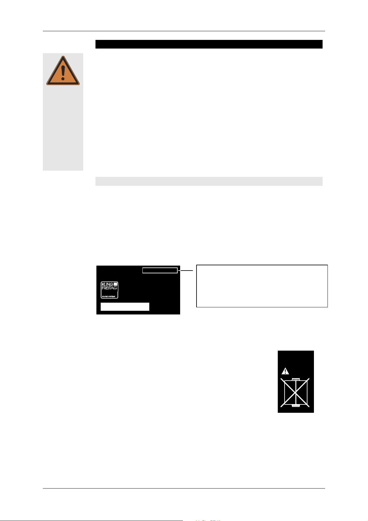
Supplementary measures which allow for an ‘old’ Click & Fly rigging system to be
used for mounting SW 215E Systems:
− Affix a new name plate, available from Kling & Freitag, recognisable by the classi-
fication 'CLICK & FLY LINE 212 / SW 215E'.
− Affix the following additional sticker, received from Kling &
Freitag, to the top side of the main bar:
DO NOT CONNECT
SPEAKERS WITH
CLICK & FLY
MAINBARS
− Receipt of a written version of this manual for each Click & Fly System.
− User's Manual made available for the user.
− Disposal of the old Users’ Manual.
Kling & Freitag GmbH has made all resources necessary for supplementation including a
detailed manual available free of charge to all buyers of the ‘old’ ‘CLICK & FLY RIGGING
SYSTEM’. If you did not receive these resources, please contact your retailer!
KLING & FREITAG GMBH ©1998 - 2015 Version 5.1, 29.05.2015 Page 13 of 13
Page 14
User's Manual K&F ‘SW’ Series Subwoofer Systems
5.2 Subwoofers with ‘Flying Thread’ M12 (SWi Versions)
If you want to use the SP subwoofers equipped with ‘flying threads’ M12, please read
the following instructions.
Appropriate fastening mechanisms with an external screw thread of M12 and a minimum length of 35 mm! may be screwed on to the M 12 thread inserts. The internal
screw threads in the speaker enclosure are fastened during production with countersunk head screws M12.
The two internal screw threads of the inner enclosure edge are on an L-bracket. This Lbracket has the function of connecting the adjoining plates of the enclosure. It provides
sufficient tensile strength for flown operations. To guarantee that the enclosure plates
are correctly connected by the L-brackets, only one screw of the enclosure edge may be
loosened at a time. If both screws of an enclosure edge become loose, then, for safety
reasons, the L-bracket will collapse into the enclosure.
If the L-bracket has fallen into the enclosure the loudspeaker must on no account be used again until it has been repaired by an authorized repair service.
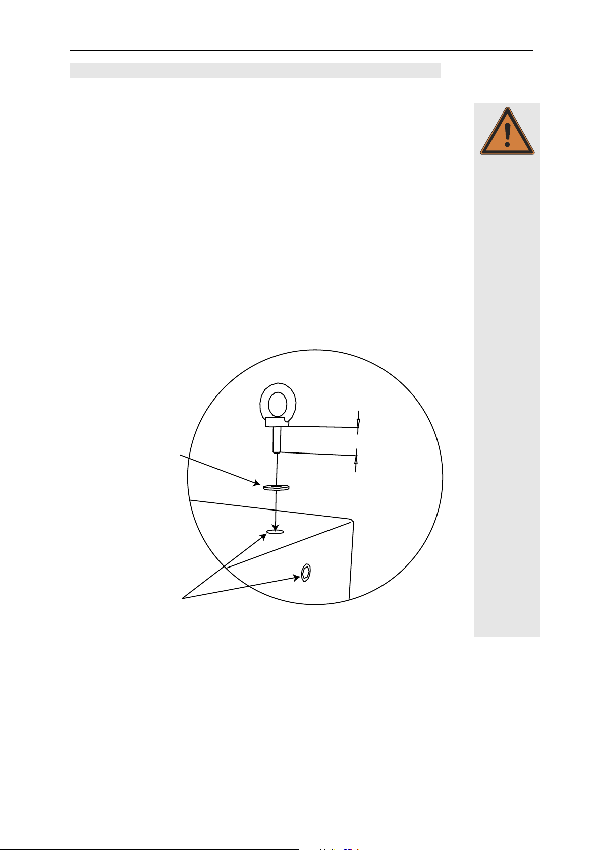
When mounting the speakers, use only fastening mechanisms with threads that extend
at least 35 mm into the speaker enclosure. Take into account the permissible load capacity of the fastening mechanisms while considering the safety factors. Mount the
speakers using at least two independently operating points. Secure all screws to prevent
loosening.
Warning
Always use flat
washers M12 with
the customary outer
diameter of 37 mm
Loosen only one of
these two screws at a
time!
35 mm minimum
KLING & FREITAG GMBH ©1998 - 2015 Version 5.1, 29.05.2015 Page 14 of 14
Page 15

User’s Manual K&F ‘SW’ Series Subwoofer Systems
5.3 Subwoofers with ‘allsafe JUNGFALK’ Flying Points
Single Stud Fitting
Used as fastener to the ‘allsafe
JUNGFALK’ flying Point.
1.)
‘allsafe JUNGFALK’ Flying Point
Receptacle for special fasteners.
2.)
Warning
Take the single stud fitting in one
hand...
3.)
Put the flat head of the holding
bolt into the guiding of the flying
point.
... and push the locking device up
against the spring tension.
4.)
Release the locking device when
the single stud fitting is located in
the middle of the flying point.
Make sure that the locking device
clicks into place.
5.)
Check that the single stud fitting is
securely fastened and cannot be
pulled out.
KLING & FREITAG GMBH ©1998 - 2015 Version 5.1, 29.05.2015 Page 15 of 15
Page 16

User's Manual K&F ‘SW’ Series Subwoofer Systems
5.4 SW 215E ‘Suspension’: Using the allsafe Flying Track
The subwoofer SW 215E with suspension option may only be suspended by using the
double stud fittings available from Kling & Freitag. The ‘allsafe JUNGFALK’ flying tracks
are used to suspend the SW 215E system.
We recommend using the certified Click & Fly Line 212 / SW 215E rigging system for
suspending the SW 212E.
The ‘allsafe JUNGFALK’ flying track can only support weights up to 73 kg on
one point!
Please follow the accompanying safety and assembly instructions carefully.
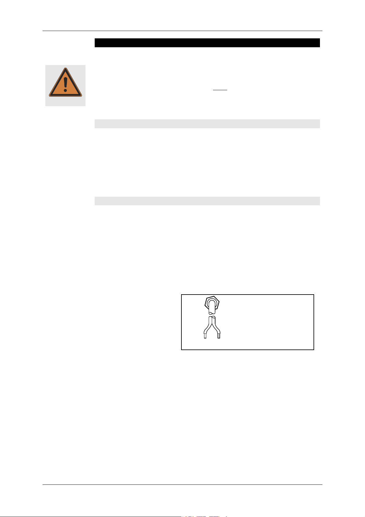
Double Stud Fitting
Used as fastener to the ‘allsafe
JUNGFALK’ Flying Point and the
‘allsafe JUNGFALK’ Flying Track.
1.)
Align the double stud fitting as
shown above and push it into the
track,…
‘allsafe JUNGFALK’ Flying Track
Receptacle for the double stud fitting.
2.)
... slide the pushed double stud fitting
to the middle of the speaker until it
clicks into place. Make sure that it is
secured tightly.
Warning
KLING & FREITAG GMBH ©1998 - 2015 Version 5.1, 29.05.2015 Page 16 of 16
Page 17

User’s Manual K&F ‘SW’ Series Subwoofer Systems
Distance
rod 334
6. Mounting Instructions for Speakers
Mount the speakers securely. To avoid injury or damage, always be sure to mount the
speakers securely so that they do not fall. Speakers, which are stacked, must be secured
with securing straps. When laying the connecting cables, make sure that nobody can
Warning
trip.
The stability of stacked systems (also valid for the use of stands and distance rods!) is
contingent upon the following stability requirement. These conditions must, therefore,
be guaranteed by the user:
Stacked systems may not fall over even if they are inclined by 10° in each direction. If this requirement is not fulfilled, then it is necessary to take steps to
achieve compliance. Possible measures include strapping it to an appropriate
base structure or fastening it using safety straps.
6.1 Using the Mounting Equipment ‘Distance Rod’
The subwoofer is equipped with a threaded flange (M20) on the top of the enclosure
for mounting the optionally available distance rod (not on the SWi versions).
All K&F top speakers with a mounting flange or stand adapter may be mounted on the
distance rod. Only use authentic Kling & Freitag distance rods and stand adapters. We
can only guarantee safe operations when these parts are used.
Caution
When a top speaker is mounted on the subwoofer using a distance rod, the stability of
the speakers is reduced. Please follow the stability requirements in chapter 6!
When re-positioning after set-up, remove the upper speaker mounted on the distance
rod first.
Special note for the model SW 112
A top speaker with a maximum weight of 28 kg (i.e. CA 1201) may be mounted on this
speaker using a distance rod. Speakers, which are heavier than 28 kg, may not be
mounted on the distance rod flange and must be mounted on an additional speaker
stand.
KLING & FREITAG GMBH ©1998 - 2015 Version 5.1, 29.05.2015 Page 17 of 17
Distance rod 337
(adjustable)
Distance rod 337
with stand adapter and
adjustable speaker mount
Page 18

User's Manual K&F ‘SW’ Series Subwoofer Systems
Stapelmulden
6.2 LINE 212 Systems on Top of SW 115E
für SW 115E
In addition to the stacking foot
grooves for stacking the same
Stapelmulden
für 'LINE 212'
enclosures, the subwoofer SW
115E also has stacking foot
grooves for the Line 212 system.
One Line 212 System can be
quickly and safely positioned on
top of the subwoofer.
Stapelmulden
für 'LINE 212' und SW 115E
6.3 LINE 212 Systems on Top of SW 215E
In addition to the stacking foot grooves for stacks of
identical enclosures, the subwoofer SW 115E also has
stacking foot grooves for the Line 212 system.
One Line 212 System can be quickly and safely positioned on top of a vertically placed SW 215E.
Two Line 212 systems can be precisely arrayed on top of
a horizontally placed SW 215E.
Horn not rotated on
standing Line 212 system
Line 212-6 --- SP
with
Line 212-6 - SP
8,5°
38,5°
Horn rotated on
standing Line 212 system
Line 212-6 --- SP
30°
with
Line 212-9 - SP
15,0°
45°
Other combinations of Line 212 Systems are not recommended as they can cause unwanted interferences. .
KLING & FREITAG GMBH ©1998 - 2015 Version 5.1, 29.05.2015 Page 18 of 18
Page 19

User’s Manual K&F ‘SW’ Series Subwoofer Systems
7. Short Circuit Fuses in the K&F Subwoofer Systems
7.1 Risks of using High Performance Power Amplifiers
In recent years, power amplifiers have achieved increasingly higher levels of performance. Some of them can be operated with low-impedance loads. There are, therefore,
strong power amplifiers that can reliably work with impedances below 1 Ω. This development has led to an increased safety risk during defective operations.
When there is a defect, such as a short circuit in the speaker chassis or on the crossover,
it is possible that the power amplifier --- despite existing protective switches --- will not
shut off. Long cable lengths and contact resistance on the plug connections may already
have an electrical resistance of 1 Ω. As a result, the power amplifier cannot ‘‘recognise’’
the operations as being defective and, therefore, delivers unacceptable high currents. In
the worst-case scenario, this may lead to fire damage (hot and charred wiring / connectors as a result of overloaded conductors and connectors, etc.).
regulations are lagging behind this development and are thus not up-to-date with this
modern technology.
In order to give consideration to this development, Kling & Freitag now equips its subwoofer systems with short circuit fuses at the signal input. These fuses do not offer
protection for the speaker, but do reduce the risk of consequential damage in the case
of a short circuit.
The current safety
For systems, which are not serially equipped with a short circuit fuse, Kling & Freitag
offers simple add-on kits so that you can adapt your existing subwoofer systems to the
current power amplifier development.
7.2 Identifying the Models with Short Circuit Fuses
The subwoofer systems, which are serially equipped with, fire safety fuses can be identified as follows; both mentioned stipulations must be fulfilled:
Adobe Systems
POWER: 700W
The first two
digits must be at
least 25.
XO-ON OFF
IMP: 6
SER.-NO.:
2 50 80 0 0 0 0 70
WT: 51,5kg
The next two
digits must be at
least 08.
All subwoofer systems, which are not serially equipped with short circuit fuses, can be, if
required, easily and inexpensively upgraded even by yourself.
An instruction manual for this upgrade is delivered with the add-on kit.
7.3 Specification of the Fuses
The fuses in all models have the following identical specifications:
Bussmann S 506
Bussmann S 506----8A slow
Bussmann S 506Bussmann S 506
8A slow
8A slow8A slow
When necessary, these fuses may only be replaced with the aforementioned original
fuse.
KLING & FREITAG GMBH ©1998 - 2015 Version 5.1, 29.05.2015 Page 19 of 19
Page 20

User's Manual K&F ‘SW’ Series Subwoofer Systems
7.4 Replacement and Positions of the Short Circuit Fuses
When the fuse is burned out, then the chassis is most likely already ruined, as the fuse
just prevents consequential damage resulting from a short circuit of the chassis.
A disassembly of the chassis is, therefore, unavoidable.
7.4.1 Subwoofers without Crossover (XO)
The fuse holder of the subwoofers without a crossover (XO) is mounted on the signal
wiring behind the input connector. The subwoofers with two chassis have 2 fuses because the chassis are intended for parallel use.
When replacing the fuse, the chassis must be removed in order to reach the fuse holder.
Unscrewing the connecting terminal does not enable you to reach the fuse holder.
When the chassis is re-assembled, first loosely fasten the screws diagonal from one
another, then tighten them. By tightening the screws diagonally in two steps, a deformation of the chassis and thus a possible de-centring of the voice coil can be avoided.
7.4.2 Subwoofers with Crossover (XO)
The fuses of the subwoofers with a crossover are serially mounted on the crossover. The
exact position is described in the chapter ‘Internal Wiring of Subwoofers with Low-Pass
Filter (XO)’ beginning on page 25 for the particular models.
If it happens to be a model, which has already been upgraded, then the fuse holder is
mounted on the signal wiring behind the input connector.
When replacing the fuse in both cases, the chassis must be removed in order to reach
the fuse holder. Unscrewing the connecting terminal does not enable you to reach the
fuse holder.
When the chassis is re-assembled, first loosely fasten the screws diagonal from one
another, then tighten them. By tightening the screws diagonally in two steps, a deformation of the chassis and thus a possible de-centring of the voice coil can be avoided.
7.5 Add-On Kits for Subwoofers without Short Circuit Fuses
All subwoofer systems, which are not serially equipped with short circuit fuses, can be, if
required, easily and inexpensively upgraded even by yourself.
An instruction manual for this upgrade is delivered with the add-on kit.
Subwoofers with a crossover that are not serially equipped with short circuit fuses can
also be, if necessary, upgraded with fire safety fuses. The crossover does not need to be
replaced. For this, we offer an add-on kit that is mounted between the crossover input
and the input connector.
KLING & FREITAG GMBH ©1998 - 2015 Version 5.1, 29.05.2015 Page 20 of 20
Page 21

User’s Manual K&F ‘SW’ Series Subwoofer Systems
1.
8. Wiring
The Speaker is equipped with two parallel-wired Speakon connectors.
Before connecting your speaker as shown in chapter 9 be sure to switch off all connected appliances and turn down all level controls.
− We recommend the use of high-quality speaker cables provided by KLING & FREITAG.
− For connections from the mixing console to the power amplifier inputs, please use 2-
pin shielded microphone cable with high-quality connectors.
− Avoid ground loops (see chapter 8.2 Avoiding Ground Loops)
− Please pay attention to the respective pin diagrams in this manual!
− Make sure that the +/- polarity between speaker and amplifier is correct. When simul-
taneously using power amplifiers from different manufacturers, be sure to use the
correct specific pin configuration. It may be necessary to modify the pin configuration
on the power amplifiers or on the connectors leading to them.
− To avoid loss of power, the cables should have a minimum wire gauge of 2.5 mm² -
more for longer cabled distances. A minimum wire gauge can be easily calculated
with the following formula:
Important
Minimum Wire Gauge (mm²) =
Required Cable Length (m)
2 x Speaker's Impedance (Ω)
If several loudspeakers are to be connected, the signal can be linked through from one
loudspeaker to the next. Please make sure that the total impedance of the loudspeakers
R(Ω) is not lower than the minimal impedance indicated on the power amplifier.
1/R1 + 1/R2 + 1/R3 + ... = 1/R
total
8.1 Connecting the Speakon Connectors to the Connecting Ter-
minal
2.
1.
2.
3.
KLING & FREITAG GMBH ©1998 - 2015 Version 5.1, 29.05.2015 Page 21 of 21
Page 22

User's Manual K&F ‘SW’ Series Subwoofer Systems
8.2 Avoiding Ground Loops
8.2.1 What is a Ground Loop?
Every component of a P.A. or Hi-Fi System has its own internal 0V reference (ground). This
point is often connected to the protective earth connector (PE / Ground). If two or more
units are connected to one another with a line level audio cable, there may be a ground
connection through the ground of the power supply cable (yellow-green) as well as
through the shielding of the audio cable. The voltage difference between these two
ground points causes audible interference to come from the speaker.
8.2.2 Avoiding Ground Loops
If there is a loud humming or buzzing after the speaker has been connected, then check
that a ‘ground loop’ has not been built into the system. Some power amplifiers and
system controllers facilitate a ground lift switch. Set these ground lift switches to the
‘Lift’ position one after the other. If the noise is still audible, check if,
1. the noise is caused by a ground loop before the power amplifiers or controllers
(e.g. mixing console, effects or equalizers).
2. the system or parts of the system are connected to an ‘unclean’ power supply meaning one which is also running large motors or lighting systems. An ‘unclean’ supply voltage, electrostatic and electromagnetic fields can cause interference.
Please observe the following basic rules:
− Never!!! try to avoid a ground loop by disconnecting or taping the protec-
tive earth contact at the mains connector! Extremely dangerous! Extremely
dangerous!
− If possible, only use high-quality audio appliances with balanced signal outputs and
with power cables with PE connectors.
− Use high-quality cables with good shielding.
− The point of ground for all connected components should merge at one central
point. The power connections should lead out in a radial manner from one point
and not be linked from one unit to the next.
− When installing appliances that create strong electrostatic or electromagnetic fields
(large transformers, switch-mode power supplies), maintain some distance from
other audio appliances. In extreme cases, the only solution is to create a completely
independent ‘audio ground’; in other cases, it is sufficient to connect a filter in front
of the audio equipment.
Warning
KLING & FREITAG GMBH ©1998 - 2015 Version 5.1, 29.05.2015 Page 22 of 22
Page 23

User’s Manual K&F ‘SW’ Series Subwoofer Systems
9. Configurations and Connecting Diagrams
9.1 Operating the Systems without K&F System Controller
The K&F subwoofers with integrated crossover (SW 112 - XO / SW 115D - XO or SW
118E - XO) can be combined with K&F top speakers by simply connecting them in parallel.
9.1.1 ‘XO ON’ Subwoofer with optional Crossover (XO)
In this mode of operation you can easily realise applications, where a higher bass level is
needed.
Important
Be sure to use only amplifiers, which can handle speaker impedances down to 3 Ω in
this mode.
When using the mid-high systems in a cluster (speakers in close proximity), reduce the
frequencies below 300 Hz by 3-4 dB!
Recommended combinations of CA systems, as described here, with K&F subwoofers:
2 CA systems + 2- 4 x SW 112-XO
or + 2 x SW 115E-XO
or + 1 - 2 x SW 118E-XO
Switch To 'XO ON' Switch To 'XO ON'
INPUT e.g. from
mixer, AUX or
Connector Panel
OUTPUTS
INPUT CH 2 INPUT CH 1
-
CH 2 CH 1
-
+
+
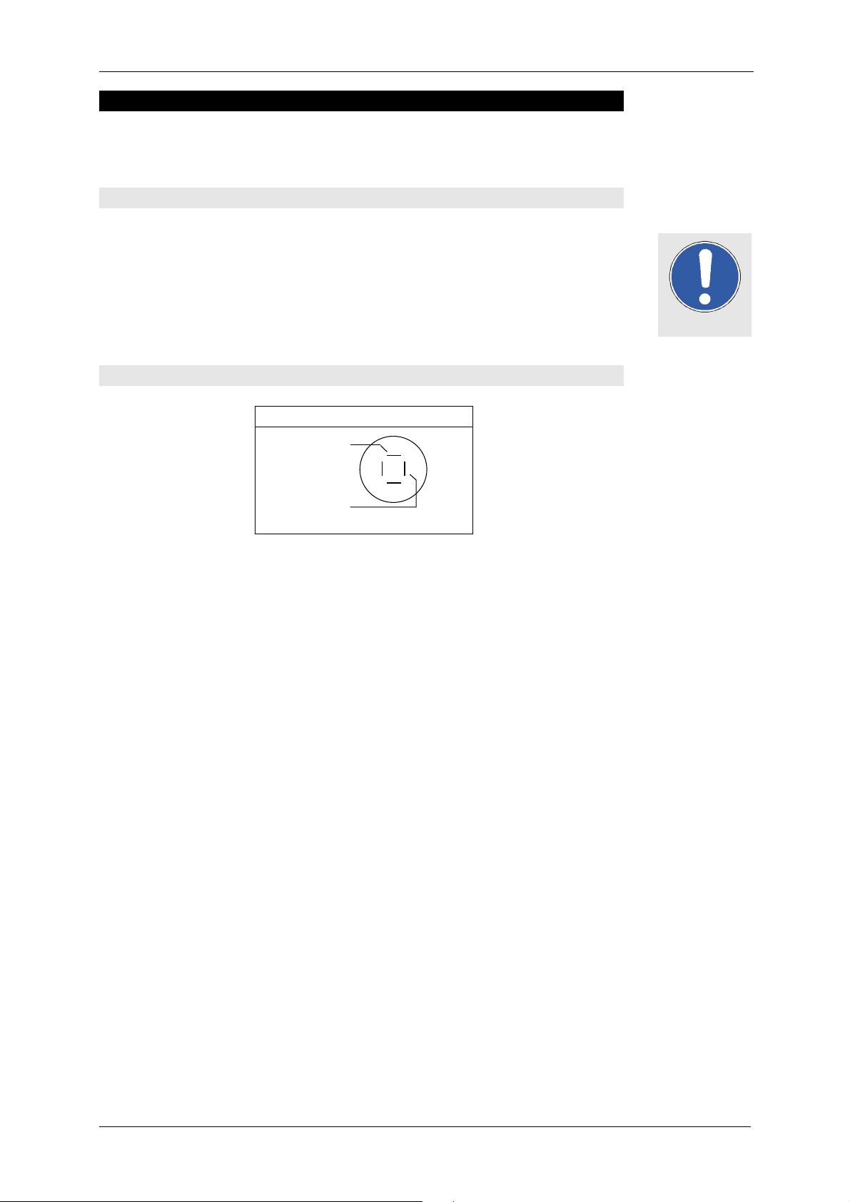
The switch XO on the connecting terminal of the subwoofer must be at ‘ON’ for this
mode of operation:
Switch on the subwoofers’ connecting terminal
KLING & FREITAG GMBH ©1998 - 2015 Version 5.1, 29.05.2015 Page 23 of 23
Page 24

User's Manual K&F ‘SW’ Series Subwoofer Systems
9.2 Operations with K&F System Controller
For optimal performance and operating safety we recommend using a K&F System
Controller. Instructions for use, connecting diagrams and detailed descriptions of the
latest controller models ‘CD 24’ and ‘CD 44’ you can find in the corresponding user’s
manuals.
10. Operating the Speakers
− Switch off all equipment and turn down all level controls.
− Wire your subwoofer systems.
− Please pay attention to the user’s manual of your power amplifier!
− Upon completing the wiring, ensure that the connected speakers are working in
phase. To do so, use i.e. a phase checker. A phase error can also be recognized when
the connected channels are used simultaneously. During simultaneous use the bass
frequencies become notably quieter or the mid-frequencies such as voices cannot be
located.
− Now switch on the peripheral equipment first (mixing console, effects etc.), followed
by the K&F System Controller and lastly the power amplifiers. Always use the before
mentioned switching order. Otherwise switching noises may damage the system.
− If there is interference, turn off all appliances in the reverse order and check all cable
connections (see chapter 8.2 , Avoiding Ground Loops).
− Successively turn up the individual power amplifier channels and send a signal
with low volume to the system. Check to see if the desired signals are applied to
the intended speakers and make sure there is no interference. Make sure everything works properly, i.e. if the signals come from the correct speaker paths (high
signals from the tweeters, bass signals from the bass speaker). Your system should
now be ready for operation.
Important
KLING & FREITAG GMBH ©1998 - 2015 Version 5.1, 29.05.2015 Page 24 of 24
Page 25

User’s Manual K&F ‘SW’ Series Subwoofer Systems
IN OUT
11. Internal Wiring of Subwoofers with Low-Pass Filter (XO)
11.1 SW 112 - XO / SW 118E - X0
Short circuit fuse:
Bussmann S 506
Bussmann S 506----8A slow
Bussmann S 506Bussmann S 506
8A slow
8A slow8A slow
(Only if serially equipped
with short circuit fuse)
LF
2-2+ 1-1+ 2-2+1-1+
Pin assignment Speakon NL4
‘IN’ 1+ 1- 2+ 2‘OUT’ parallel with ‘IN’
+ - / /
-
IN-+
LF
+
Switch
(Rear)
A1 B4
-
A2
+
B5
A3
B6
KLING & FREITAG GMBH ©1998 - 2015 Version 5.1, 29.05.2015 Page 25 of 25
Page 26

User's Manual K&F ‘SW’ Series Subwoofer Systems
IN OUT
11.2 SW 115E - XO
Short circuit fuse:
Bussmann S 506
Bussmann S 506----8A slow
Bussmann S 506Bussmann S 506
8A slow
8A slow8A slow
-
+
IN IN
+
-
LFLF
Switch
(Rear)
A1 B4
-
LF
2-2+ 1-1+ 2-2+1-1+
Pin assignment Speakon NL4
‘IN’ 1+ 1- 2+ 2‘OUT’ parallel with ‘IN’
+ - / /
+
A2
B5
A3
B6
12. Touching Up Damage to Paint / Changing the Front Foam
Although the PU structured paint used by KLING & FREITAG is extremely resistant, we
recommend using protective covers or cases to help avoid damaging the paint during
i.e. continuous mobile use. If paint damage occurs despite these precautions, it can be
touched up by using commercial acrylic paint in the appropriate RAL colour of the
speaker. To replace the filter foam, send the front grille incl. foam to KLING & FREITAG
GmbH. Upon payment for expenses, the grille with the new covering will be returned.
KLING & FREITAG GMBH ©1998 - 2015 Version 5.1, 29.05.2015 Page 26 of 26
Page 27

User’s Manual K&F ‘SW’ Series Subwoofer Systems
13. Technical Specifications
13.1 SW 112
Speaker
Design
Bass reflex system with exponential
tunnel geometry
Frequency range -10 dB 35 Hz --- 2.5 kHz
Frequency range ±3 dB 41 Hz - 350 Hz
Crossover frequencies max. 110 Hz with optional
low-pass filter (XO 'ON')
Power handling 500 W nominal
1000 W programme
Sensitivity 1 W / 1 m 92 dB (45 Hz - 350 Hz)
1)
2)
3)
93 dB (40 Hz - 110 Hz) with optional low-
pass filter (XO 'ON')
Max. SPL 124 dB (peak / 1 m / free field,
equivalent 130 dB half room)
Components 1 x 12‘‘ long excursion chassis, 100 mm
voice coil, internal and external ventilation
Impedance (nom.) XO 'ON'
Without crossover, XO 'OFF'
6 Ω, Zmin. 4 Ω
8 Ω, Zmin. 6 Ω
Connectors 2 x Speakon NL4MP (1+/1-)
Enclosure
15 mm frame reinforced Multiplex plywood
with highly resistant black structured paint (PU)
1 ergonomic handle
K&M mounting plate M20 for
distance rod, 4 non-abrasive
plastic feet,
stacking foot grooves
for stacks of identical
enclosures
ball-proof steel grille with exchangeable
black acoustic foam
Dimensions (W x H x T) 470 x 370 x 520 mm
Weight 27 kg / 28.7 kg with low-pass filter
Options 'XO' switchable low-pass filter,
'Barrier strip' instead of Speakon connector,
'100 Volt' with 300 VA toroidal transformer
(29.5 kg) --- not in combination with option 'XO'
‘Suspension‘ with 6 flying points ‘allsafe JUNGFALK'
'Outdoor Mobile'
Special finish in RAL colours
Accessories see catalogue or visit www.kling-freitag.de
1)
Pink noise 40 --- 400 Hz, 2 h; 2) as 1) but with 50% duty cycle; 3) 2.83 Vrms, free field
KLING & FREITAG GMBH ©1998 - 2015 Version 5.1, 29.05.2015 Page 27 of 27
Page 28

User's Manual K&F ‘SW’ Series Subwoofer Systems
13.2 SWi 112
Speaker
Design Bass reflex system with exponential
tunnel geometry
Frequency range -10 dB 35 Hz --- 2.5 kHz
Frequency range ±3 dB 41 Hz - 350 Hz
Crossover frequencies 110 Hz with optional low-pass filter (XO 'ON')
Power handling 500 W nominal
1000 W programme
Sensitivity 1 W / 1 m 92 dB (45 Hz - 350 Hz)
Max. SPL 124 dB (SPL Peak / 1 m / free field,
equivalent 130 dB half room)
Components 12‘‘ long excursion chassis, 100 mm
voice coil, internal and external ventilation
Impedance (nominal)
6 Ω, Zmin. 4 Ω (XO 'ON')
8 Ω, Zmin. 6 Ω (XO 'OFF')
Connectors 2 x Speakon NL4MP (1+/1-)
Enclosure
15 mm frame reinforced Multiplex plywood
with highly resistant black structured paint (PU)
ball-proof steel grille with exchangeable
black acoustic foam
Rigging 12 x M 12 thread inserts
Dimensions (W x H x D) 470 x 370 x 520 mm (incl. castors)
Weight 27 kg
Options 'XO' switchable low-pass filter,
'Barrier strip' instead of Speakon connector,
'100 Volt' with 300 VA toroidal transformer
(29.5 kg) - not in combination with option 'XO'
'Special finish in RAL colours'
Accessories see catalogue or visit www.kling-freitag.de
1)
Pink noise 40 --- 400 Hz, 2 h; 2) as 1) but with 50% duty cycle; 3) 2.83 Vrms, free field
1)
2)
3)
KLING & FREITAG GMBH ©1998 - 2015 Version 5.1, 29.05.2015 Page 28 of 28
Page 29

User’s Manual K&F ‘SW’ Series Subwoofer Systems
13.3 SW 115E
Speaker
Design Bass reflex system with exponential
tunnel geometry
Frequency range -10 dB 37 Hz - 320 Hz
Frequency range ±3 dB 43 Hz - 150 Hz
Power handling 750 W nominal
1500 W programme
Sensitivity 1 W / 1 m 95 dB (37 Hz - 320 Hz)
Max. SPL 127 dB (SPL Peak / 1 m free field,
equivalent 133 dB half room)
Components 15‘‘ long excursion chassis, double centred
100 mm voice coil,
internal and external ventilation,
Aluminium demodulation ring
Impedance (nominal)
8 Ω, Zmin. 6,2 Ω (XO 'OFF' or without filter)
6 Ω, Zmin. 4.5 Ω (XO 'ON')
Connectors 2 x Speakon NL4MP (1+/1-)
Enclosure
15 mm frame reinforced Multiplex plywood
with highly resistant black structured paint (PU)
2 ergonomic butterfly handles,
K&M mounting plate M 20 for distance rod,
4 non-abrasive plastic feet,
enclosures or SW 215E / Line 212,
2 locking profiles for optional transport cover,
ball-proof steel grille with exchangeable
black acoustic foam
Dimensions (W x H x D) 470 x 515 x 640 mm
stacking foot grooves for stacks of identical
Weight 35 kg / 37 kg with option 'XO'
Options 'XO' with switchable low-pass filter, crossover
frequency 110 Hz,
'Barrier strip' instead of Speakon connector,
'Outdoor Mobile',
'Special finish in RAL colours'
Accessories see catalogue or visit www.kling-freitag.de
1)
Pink noise 40 --- 400 Hz, 2 h;
2)
as 1) but with 50% duty cycle; 3) 2.83 Vrms, free field
1)
2)
3)
KLING & FREITAG GMBH ©1998 - 2015 Version 5.1, 29.05.2015 Page 29 of 29
Page 30

User's Manual K&F ‘SW’ Series Subwoofer Systems
13.4 SWi 115E
Speaker
Design Bass reflex system with exponential
tunnel geometry
Frequency range -10 dB 37 Hz - 320 Hz
Frequency range ±3 dB 43 Hz - 150 Hz
Sensitivity 1 W / 1 m 110 Hz with optional low-pass filter (XO 'ON')
Power handling 750 W nominal
1500 W programme
Sensitivity 1 W / 1 m 95 dB 37 Hz - 320 Hz (43 Hz - 150 Hz)
Max. SPL 127 dB (SPL Peak / 1 m free field,
equivalent 133 dB half room)
Components 15‘‘ long excursion chassis, double
centred 100 mm voice coil,
internal and external ventilation,
Aluminium demodulation ring for minimal
distortions
Impedance (nominal)
6 Ω, Zmin. 4,5 Ω (XO 'ON')
8 Ω, Zmin. 6,2 Ω (XO 'OFF' or without filter)
Connectors 2 x Speakon NL4MP (1+/1-)
Enclosure
15 mm frame reinforced Multiplex plywood
with highly resistant black structured paint (PU)
ball-proof steel grille with exchangeable
black acoustic foam
Rigging 12 x M12 thread inserts
Dimensions (W x H x D) 470 x 504 x 640 mm
Weight 35.3 kg / 37,3 kg with option 'XO'
Options 'XO' switchable low-pass filter, crossover
frequency at 110 Hz,
‘Barrier strip’ instead of Speakon connectors,
'Special finish in RAL colours'
Accessories see catalogue or visit www.kling-freitag.de
1)
Pink noise 40 --- 400 Hz, 2 h; 2) as 1) but with 50% duty cycle; 3) 2.83 Vrms, free field
1)
2)
3)
KLING & FREITAG GMBH ©1998 - 2015 Version 5.1, 29.05.2015 Page 30 of 30
Page 31

User’s Manual K&F ‘SW’ Series Subwoofer Systems
13.5 SW 118E
Speaker
Design Bass reflex system with exponential
tunnel geometry
Frequency range -10 dB 30 Hz --- 2.5 kHz
Frequency range ±3 dB 38 Hz - 300 Hz
Crossover frequencies 110 Hz with optional low-pass filter (XO 'ON')
Power handling 700 W nominal
1400 W programme
Sensitivity 1 W / 1 m 97 dB (40 Hz - 300 Hz)
Max. SPL 134 dB (SPL peak / 1 m / free field,
equivalent 140 dB half room)
Components 18‘‘ long excursion chassis, double
centred 100 mm voice coil,
internal and external ventilation,
demodulation ring (double DDR) for
minimised distortions
Impedance (nom.) XO 'ON'
without filter or XO 'OFF'
6 Ω, Zmin. 4 Ω
8 Ω, Zmin. 6 Ω
Connectors 2 x Speakon NL4MP (1+/1-)
Enclosure
15 mm frame reinforced Multiplex plywood
with highly resistant black structured paint (PU)
4 ergonomic butterfly handles,
K&M mounting plate M20 for
distance rod,
4 non-abrasive plastic feet,
4 stacking foot grooves for stacks of identical
enclosures,
2 locking profiles for optional transport cover
ball-proof steel grille with exchangeable
black acoustic foam
Rigging 4 flying points 'allsafe JUNGFALK'
Dimensions (W x H x D) 600 x 680 x 766 mm (incl. castors)
Weight 49.8 kg
Options 'XO' with switchable low-pass filter,
'Barrier strip' instead of Speakon connector,
'without 100 mm transport castors’,
'Outdoor Mobile',
'Special finish in RAL colours'
Accessories see catalogue or visit www.kling-freitag.de
1)
Pink noise 40 --- 400 Hz, 2 h;
2)
as 1) but with 50% duty cycle; 3) 2.83 Vrms, free field
1)
2)
3)
KLING & FREITAG GMBH ©1998 - 2015 Version 5.1, 29.05.2015 Page 31 of 31
Page 32

User's Manual K&F ‘SW’ Series Subwoofer Systems
13.6 SWi 118E
Speaker
Design Bass reflex system with exponential
tunnel geometry
Frequency range -10 dB 30 Hz --- 2.5 kHz
Frequency range ±3 dB 38 Hz - 300 Hz
Crossover frequencies 110 Hz with optional low-pass filter (XO 'ON')
Power handling 700 W nominal
1400 W programme
Sensitivity 1 W / 1 m 97 dB (40 Hz - 300 Hz)
Max. SPL 134 dB (SPL peak / 1 m / free field,
equivalent 140 dB half room)
Components 18‘‘ long excursion chassis, double
centred 100 mm voice coil,
internal and external ventilation,
demodulation ring (double DDR) for minimised
distortions
Impedance (nom.) XO 'ON'
without filter or XO 'OFF'
6 Ω, Zmin. 4 Ω
8 Ω, Zmin. 6 Ω
Connectors 2 x Speakon NL4MP (1+/1-)
Enclosure
15 mm frame reinforced Multiplex plywood
with highly resistant black structured paint (PU)
ball-proof steel grille with exchangeable
black acoustic foam
Rigging 12 x M 12 thread inserts
Dimensions (W x H x D) 600 x 672 x 640 mm
Weight 46.2 kg
Options 'XO' switchable low-pass filter,
'Barrier strip' instead of Speakon connector,
'Outdoor Installation',
'Special finish in RAL colours'
Accessories see catalogue or visit www.kling-freitag.de
1)
Pink noise 40 --- 400 Hz, 2 h; 2) as 1) but with 50% duty cycle; 3) 2.83 Vrms, free field
1)
2)
3)
KLING & FREITAG GMBH ©1998 - 2015 Version 5.1, 29.05.2015 Page 32 of 32
Page 33

User’s Manual K&F ‘SW’ Series Subwoofer Systems
13.7 SW 215E
Speaker
Design Bass reflex system with exponential
tunnel geometry
Frequency range -10 dB 36 Hz - 1 kHz
Frequency range ±3 dB 42 Hz - 250 Hz
Crossover frequencies max. 200 Hz
Power handling 1500 W nominal1)
3000 W programme2)
Sensitivity 1 W / 1 m 98 dB (42 Hz - 150 Hz)
Max. SPL 133 dB (peak / 1 m / free field,
equivalent 139 dB half room)
2 x 15‘‘ long excursion chassis, 100 mm
Components voice coil with double centring,
internal and external ventilation,
demodulation ring (double DDR) for minimal
distortion
Impedance (nominal)
4 Ω, Zmin. 3.1 Ω
Connectors 2 x Speakon NL4MP (1+/1-)
Enclosure
15 mm frame reinforced Multiplex plywood
with highly resistable black structured paint (PU)
4 ergonomic butterfly handles,
4 integrated handles,
K&M mounting plate M20 for distance rod,
8 non-abrasive plastic feet,
stacking foot grooves for stacks of identical
enclosures as well as for single or clustered
Line 212 enclosures
4 x 100 mm rear mounted castors,
2 locking profiles for optional transport cover,
ball-proof steel grille with exchangeable
black acoustic foam
Dimensions (W x H x D) 480 x 1015 x 765 mm (incl. castors)
Weight 68.5 kg
'Barrier strip' instead of Speakon connector,
‘without 100 mm transport castors’,
Options
‘Suspension’ with 6 flying tracks 'allsafe JUNGFALK',
'Outdoor Mobile',
'Special finish in RAL colours'
Accessories see catalogue or visit www.kling-freitag.de
1)
Pink noise 40 --- 400 Hz, 2 h; 2) as 1) but with 50% duty cycle; 3) 2.83 Vrms, free field
3)
KLING & FREITAG GMBH ©1998 - 2015 Version 5.1, 29.05.2015 Page 33 of 33
Page 34

User's Manual K&F ‘SW’ Series Subwoofer Systems
SPL
(dB)
SPL (dB)
SPL
(dB)
SPL (dB)
14. Frequency Diagrams
14.1 SW 112 / SWi 112
14.1.1 Without optional Low-Pass Filter or ‘XO OFF’
Impedance (Ohm)
100
316
90
80
70
60
20 100 1000
Frequency (Hz)
14.1.2 With optional Low-Pass Filter ‘XO ON’
100
90
80
70
100
31,6
Impedance (Ohm)
10
3,16
Impedance (Ohm)
316
100
31,6
Impedance (Ohm)
10
60
20 100 1000
Frequency (Hz)
3,16
KLING & FREITAG GMBH ©1998 - 2015 Version 5.1, 29.05.2015 Page 34 of 34
Page 35

User’s Manual K&F ‘SW’ Series Subwoofer Systems
Impedance (Ohm)
Impedance (Ohm)
14.2 SW 115E / SWi 115E
14.2.1 Without optional Low-Pass Filter or ‘XO OFF’
SPL (dB)
Impedance (Ohm)
105
316
95
85
SPL(dB)
75
65
20 100 1000
Frequency (Hz)
14.2.2 With optional Low-Pass Filter ‘XO ON’
105
95
85
SPL(dB)
100
31,6
10
3,16
SPL (dB)
Impedance (Ohm)
316
100
31,6
75
65
20 100 1000
Frequency (Hz)
10
3,16
KLING & FREITAG GMBH ©1998 - 2015 Version 5.1, 29.05.2015 Page 35 of 35
Page 36

User's Manual K&F ‘SW’ Series Subwoofer Systems
SPL
(dB)
SPL (dB)
SPL
(dB)
SPL (dB)
14.3 SW 118E / SWi 118E
14.3.1 Without optional Low-Pass Filter or ‘XO OFF’
Impedance (Ohm)
110
316
100
90
80
70
20 100 1000
Frequency (Hz)
14.3.2 With optional Low-Pass Filter ‘XO ON’
110
100
90
80
100
31,6
Impedance (Ohm)
10
3,16
Impedance (Ohm)
316
100
31,6
Impedance (Ohm)
10
70
20 100 1000
Frequency (Hz)
3,16
KLING & FREITAG GMBH ©1998 - 2015 Version 5.1, 29.05.2015 Page 36 of 36
Page 37

User’s Manual K&F ‘SW’ Series Subwoofer Systems
Impedance (Ohm)
14.4 SW 215E
SPL (dB)
Impedance (Ohm)
110
316
100
90
SPL(dB)
80
70
20 100 1000
Frequency (Hz)
100
31,6
10
3,16
KLING & FREITAG GMBH ©1998 - 2015 Version 5.1, 29.05.2015 Page 37 of 37
Page 38

User's Manual K&F ‘SW’ Series Subwoofer Systems
DIMENSIONS
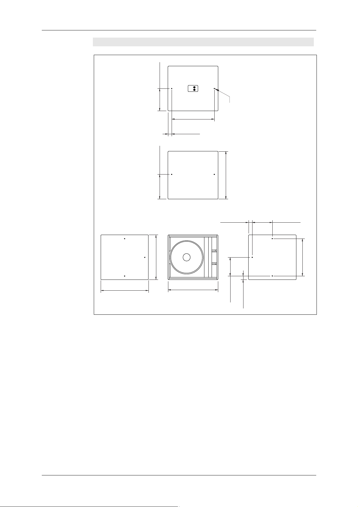
15. Dimensions
15.1 SW 112
235 mm
[9.252"]
[12.598"]
320 mm
[1.968"]
50 mm
Flugpunkte
520 mm
[20.472"]
ANCRA Jungfalk
120030-31
(nur mit Option 'Flug'!)
Befestigungsplatte für
Distanzrohre M20
470
[18.503"]
235 mm
[9.252"]
[7.874"]
200 mm
[20.472"]
520 mm
[14.566"]
370 mm
50 mm
[1.968"]
[10.236"]
260 mm
370 mm
[14.566"]
470 mm
[18.503"]
KLING & FREITAG GMBH ©1998 - 2015 Version 5.1, 29.05.2015 Page 38 of 38
Page 39

User’s Manual K&F ‘SW’ Series Subwoofer Systems
DIMENSIONS
15.2 SWi 112
235 mm
[9.252"]
[12.598"]
320 mm
320 mm
[12.598"]
[1.968"]
50 mm
[1.968"]
50 mm
Flugpunkte, Innengewinde M12
520 mm
[20.472"]
[9.252"]
235 mm
470 mm
[18.503"]
[1.968"]
50 mm
[20.472"]
520 mm
[14.566"]
370 mm
[10.629"]
270 mm
370 mm
[14.566"]
50 mm
[1.968"]
470 mm
[18.503"]
KLING & FREITAG GMBH ©1998 - 2015 Version 5.1, 29.05.2015 Page 39 of 39
Page 40

User's Manual K&F ‘SW’ Series Subwoofer Systems
DIMENSIONS
15.3 SW 115E
640 mm
[25.197 "]
Kunststoffgleitfüße
Stapelmulden
470 mm
[18.504 "]
Stapelmulden
für 'LINE 212'
Befestigungsplatte M 20 für
Distanzrohre (K&M 24115)
[19.843 "]
504 mm
[0.433 "]
11 mm
KLING & FREITAG GMBH ©1998 - 2015 Version 5.1, 29.05.2015 Page 40 of 40
Page 41

User’s Manual K&F ‘SW’ Series Subwoofer Systems
DIMENSIONS
15.4 SWi 115E
235 mm
[9.252 "]
[1.969 "]
[17.874 "]
454 mm
50 mm
640 mm
[25.197 "]
340 mm
[13.386 "]
[1.969 "]
50 mm
10 x Flugpunkte,
[1.969 "]
50 mm
470 mm
[18.504 "]
[13.386 "]
340 mm
[19.843 "]
504 mm
[1.969 "]
50 mm
235 mm
[9.252 "]
Innengewinde M12
[13.386 "]
340 mm
50 mm
[1.969 "]
KLING & FREITAG GMBH ©1998 - 2015 Version 5.1, 29.05.2015 Page 41 of 41
Page 42

User's Manual K&F ‘SW’ Series Subwoofer Systems
DIMENSIONS
15.5 SW 118E
gleitfüße
Kunststoff-
[22.535 "]
572.4 mm
ANCRA
Jungfalk
Flugpunkte
(120030-31)
310 mm
[12.205 "]
[1.961 "]
49.8 mm
640 mm
[25.197 "]
770 mm
[30.315 "]
[1.961 "]
49.8 mm
600 mm
[23.622 "]
[26.457 "]
672 mm
[0.394 "]
10 mm
Befestigungsplatte für
Distanzrohre M20
(K&M 24115)
[25.197 "]
640 mm
600 mm
[23.622 "]
300 mm
[11.811 "]
[12.205 "]
310 mm
KLING & FREITAG GMBH ©1998 - 2015 Version 5.1, 29.05.2015 Page 42 of 42
Page 43
User’s Manual K&F ‘SW’ Series Subwoofer Systems
DIMENSIONS
15.6 SWi 118E
300 mm
[11.811"]
[22.534"]
572.4 mm
330 mm
[12.992"]
[1.961"]
49.8 mm
Flugpunkte,
Innengewinde M12
640 mm
[25.196"]
[1.961"]
49.8 mm
600 mm
[23.621"]
[25.196"]
640 mm
[26.456"]
672 mm
[9.851"]
250.2 mm
49.8 mm
[1.960"]
[10.637"]
270.2 mm
500.4 mm
[19.701"]
KLING & FREITAG GMBH ©1998 - 2015 Version 5.1, 29.05.2015 Page 43 of 43
Page 44

User's Manual K&F ‘SW’ Series Subwoofer Systems
DIMENSIONS
15.7 SW 215E
470 mm
[18.504"
[5.054"]
128.37 mm
Clustermulden für
Lautsprecher 'LINE 212'
Stapelmulden
640 mm
[25.197"]
[39.961"]
1015 mm
Flugschiene
Ancra Jungfalk
(Nur mit Option 'Flug')
Kunststoff-
[12.008"]
305 mm
Befestigungsplatte für
gleitfüße
[19.980"][0.433"]
507.5 mm
Distanzrohre M20
11 mm
Stapelmulden
Stapelmulden für
Lautsprecher 'LINE
KLING & FREITAG GMBH ©1998 - 2015 Version 5.1, 29.05.2015 Page 44 of 44
Page 45

User’s Manual K&F ‘SW’ Series Subwoofer Systems
Fehler! Kein gültiger Dateiname.
KLING & FREITAG GMBH ©1998 - 2015 Version 5.1, 29.05.2015 Page 45 of 45
 Loading...