

Page 1
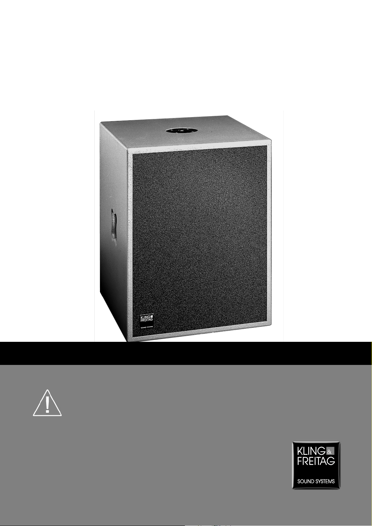
KLING & FREITAG SW 115D-XO
User’s Manual
Important Information,
Please Read before Use!
KLING & FREITAG GmbH
Junkersstrasse 14
D-30179 Hannover
TEL 0 (049) 511- 969 97-0
FAX 0 (049) 511- 67 37 94
www.kling-freitag.de
Page 2
User's Manual
Thank you for your decision to buy a KLING & FREITAG product. To guarantee a trouble-free
operating of the equipment and to enable the KLING & FREITAG PA-System to achieve its full
potential, please read the operating instructions carefully before use.
With the purchase of an SW 115D-XO, you have acquired speakers with the highest possible
quality and performance capabilities.
As the owner of an SW 115D-XO - System, you now have a versatile and highly professional
tool which, when operated properly, is a true pleasure to use.
Contents
Chapter Page
Symbols in User’s Manual 2
Information about this User’s Manual 2
1. General Instructions for Using Speakers 3
2. Wiring and Pin Diagrams of Connectors 4
3. Passive (XO ON) and Active Operations (XO OFF) 5
4. Combination with other Systems 6
5. Touching Up Damage to Paint / Changing the Front Foam 6
6. Mounting Devices and Usage of the Distace Rod 7
7. Specifications 8
Speaker System SW 115D-XO
Symbols in User’s Manual
The following symbols in this manual are included to assist the user with the installation and assembly instructions. They are also used to draw attention to the various safety warnings :
This warning symbol indicates possible dangerous
situations resulting from improper assembly or use.
Information about the application, assembly and
oper-ation of the described products and features.
Information about this User’s Manual
User’s Manual SW 115D-XO Version 2.1 01/2002
© by Kling & Freitag GmbH, André Schweimler, September 2001; all rights reserved
All specifications in this manual are based on information available at the time of publishing for the features and
safety guidelines of the described products.
Technical specifications, measurements, weights and properties are not guaranteed.
The manufacturer reserves the right to make product alterations within legal provisions as well as changes to
improve product quality.
Please keep these instructions for future reference!
We appreciate any input with suggestions and improvements for this manual. Please send this to us at
the following address:
info@kling-freitag.de or to:
KLING & FREITAG GMBH, Junkersstr.14, D-30179 Hannover, Tel: ++49 (0)511-96 99 70 Fax: ++49 (0)511-67 37 94
KLING & FREITAG GMBH ©2001
2
Page 3

User's Manual
1. General Instructions for Using Speakers
Mounting the speakers
To avoid injury or damage, always be sure to mount the speakers securely so that they do not fall.
The SW 115D-XO is designed for standing operation on the floor only. Do not hang the loudspeaker.
Ensure that all installation connections comply with the applicable safety guidelines and that the
size and strength are sufficient. Further instructions are in our user’s manual for assembly equipment and in the general safety instructions for speakers and assembly equipment.
For mobile and fixed installations, use only assembly equipment from KLING & FREITAG. Additionally, the assembly and safety instructions as described in the user’s manual for assembly equipment must be followed.
If using a SW 115D-XO for fixing a Distance Rod and a corresponding mid-high system, please
mind the significant leverage effect on the Distance Rod 's upper end. When re-positioning after
set-up, remove the upper speaker mounted on the Distance Rod first.
The subwoofer must be carried by two people.
Mounting equipment and speakers must be visually inspected on a regular basis. If wear is evident, the part must be replaced immediately. Furthermore, all screwed connections must be
checked regularly.
Speaker System SW 115D-XO
Do not Install Speakers in any of the Following Places:
-
Where the speakers are permanently exposed to direct sunlight (with the exception of the ‘All
Weather’ versions, which were specially developed for outdoor use).
-
Where the speakers are exposed to high moisture (with the exception of the ‘All Weather’
and ‘Outdoor’ versions, provided the latter are not directly subjected to weather conditions).
-
Where the speakers are exposed to strong vibrations and dust.
Damage Caused by the Speakers’ Magnetic Fields
Speakers are permanently surrounded by a magnetic field even when they are not operating.
Therefore, during transport and placement of the speakers, it is important to ensure that there is
always approx. 1 m between the speakers and magnetic data media and computer/video monitors.
Protecting the Speakers
When selecting power amplifiers, ensure that they have a sufficient power level. Power amplifiers
with an output level which is too low can cause the speakers to overload (clipping).
Power amplifiers should never be overloaded. When the nominal power of the power amplifiers is
higher than that of the speaker, overload may ruin the speaker.
The Following Signals may Damage the Speakers
-
permanent high-pitched signals with high frequency, and continuous noise from feedback.
-
permanently distorted signals with high power.
-
noises which occur when the amplifier is on while equipment is being connected, discon-
nected or switched on.
Preventing Hearing Damage
To prevent the risk of hearing damage, avoid being too close to operating speakers even if the
volume level seems to be low enough.
KLING & FREITAG GMBH ©2001
3
Page 4

User's Manual
2. Wiring and Pin Diagrams of Connectors
Wiring:
When using two or more speakers, make sure that the +/- polarity of the speakers at the amplifier
is correct in order to ensure an in-phase operation and, consequently, an homogeneous sound.
It is advisable to use connecting wires from KLING & FREITAG. To avoid loss of power, the cables
should have a minimum wire gauge of 2.5 mm² - more for longer cabled distances. A minimum
wire gauge can be easily calculated with the following formula:
Required Cable Length (m)
Minimum Wire Gauge (mm²) =
2 x Speaker Impedance (Ω)
The speaker is equipped with two parallel Speakon NL4 connectors (or, on special versions, with
two XLR connectors each) . The pin diagrams are illustrated in the following table.
When using 4-pin cables with Speakon connectors, the connector pins 2+ / 2- can be used to
transmit other audio signals.
When using the special XLR connector, make sure that the XLR-male (exposed plug contact) is
used as an input so that nobody comes in contact with the dangerous current.
Speaker System SW 115D-XO
The pin diagram for the 100V version is found on the label on the connecting terminal.
If several loudspeakers are connected, the signal can be linked through from one loudspeaker to
the next. Ensure that the total impedance of the loudspeakers R (
Ω) is not lower than the minimal
impedance indicated on the power amplifier.
+ 1/R2 + 1/R3 + ... = 1/R
(1/R
1
K&F
SW 115 D
total
)
--
LF
++
IN
KLING & FREITAG GMBH ©2001
LF
Switch
(Backside)
A1 B4
+
2-2+1-1+ 2-2+1-1+
A2
B5
A3
B6
4
Page 5

User's Manual
3. „Passive“ (XO ON) and „Active Operations“ (XO OFF)
The switchable low pass filter (XO) enables the SW 115D-XO to operate in passive mode as well as in
active mode when used with a mid-high system.
The switch for these operating modes is found on the connecting terminal on the back side of the
SW 115D-XO.
Passive Operations (XO ON):
Example:
2-way passive operations with parallel tops CA 1201 and 1 x 2 channel
power amplifier.
The passive operating mode is easy to run and cost-effective. Mid-high systems with one power amplifier can be operated in conjunction with the SW 115D without using an additional crossover or controller. In this mode of operation, the SW 115D–XO is controlled via the built-in low pass filter and can
be operated up to approx. 120 Hz.
For passive operations, connect the output of the power amplifier with the input socket of the SW
115D-XO. Then connect the output socket of the subwoofers with the input socket of the mid-high
system. The switch on the connecting terminal must be on “PASSIVE” (XO OFF).
Speaker System SW 115D-XO
Limitations of Passive Operations:
− During passive operations, it is not possible to adjust the level of the subwoofer separately.
− During passive operations, the mid-high systems also receive the low-frequency signal and are,
therefore, subject to higher strain.
Active Operations (XO OFF):
Example:
2-way active operations with Tops CA
1201. Separated by the C2 Controller
and optimally controlled tops and subwoofer connected to 2 power amplifiers.
During active operations, the audio signal is separated into a bass and a mid-high signal before it
reaches the power amplifier. This is done by a controller (optimally, a K&F C2 Controller) or an electronic crossover. The bass as well as the mid-high range each require a separate power amplifier.
For active operations, the switch on the connecting terminal of the woofer must be in the ACTIVE position (XO OFF). By doing so, an internal passive crossover is switched off.
The SW 115D-XO is an ideal supplement for active operations of all K&F full-range systems.
For an optimal acoustic coupling of the SW 115D-XO to an appropriate full-range system, the C2 Con-
troller must be equipped with a modular SW 115D plug-in card and a plug-in card for the selected fullrange system.
The C2 Controller adapts the phase and time alignment of the various full-range systems to match
those of the subwoofer systems. By using carefully selected modular filter cards (EQ), the C2 Controller
minimizes the risk of feedback and optimizes the frequency range of the given speaker systems. Further connecting instructions can be found in the documentation of your electronic crossover or your
(C2) Controller.
The advantages of active operations:
− Possibility to separately adjust the level of the subwoofer.
− The mid-high systems do not receive any low-frequency signals and are not as strained.
− While taking the various mid-high systems, the crossover of the total system can be optimized
application-specifically.
− The C2 Controller optimizes the operating safety through special limiters.
KLING & FREITAG GMBH ©2001
5
Page 6

User's Manual
4. Combination with other Systems
The following system combinations within the Kling & Freitag program are available for the passive
operating mode. (see also KLING & FREITAG Product Guide).
For a balanced volume relation between bass and mid-high systems, we recommend the following
ratio of tops to bass systems:
Passive operations with tops larger than/comparable to CA 1201:
1 top : 1 SW 115D-XO
Example:
CA1201 (2 x) with 2 x SW 115D-XO
CA1215 (2 x) with 2 x SW 115D-XO
CA1515 (2 x) with 2 x SW 115D-XO
Speaker System SW 115D-XO
Passive operations with tops smaller than CA 1201:
The number of bass systems should be reduced. Furthermore, the signal can only be transmitted to
the subwoofer from one of the tops.
Example:
CA 205 (2 - 4 x) with 1 x SW 115D-XO
CA106 (2 - 4 x) with 1 x SW 115D-XO
Active operations:
During active operations, the SW 115D-XO is an ideal supplementary system for all K&F full-range
systems.
5. Touching Up Paint Damage / Changing the Front Foam
Although the PU structured paint used by KLING & FREITAG is extremely resistant, we recommend
using protective coverings or cases to help avoid damaging the paint during i.e. continuous mobile
use. If paint damage occurs despite these precautions, it can be touched up by using commercial
acrylic paint in the appropriate RAL color of the speaker.
To replace the filter foam, send the front grill incl. foam to KLING & FREITAG GmbH. Upon payment for expenses, the grill with the new covering will be returned.
KLING & FREITAG GMBH ©2001
6
Page 7

User's Manual
6. Mounting Devices and Usage of the Distance Rod
There is a threaded flange (M20) on the top side of the SW 115D-XO necessary for mounting a
K&F Distance Rod (also vertically adjustable) which is available as an optional accessory. The Tops
CA 1201(M), CA 1215-6 / -9 (M), or CA 1515 can be used with this adapter. When mounting
smaller speakers, such as the CA 106, CA 205 and E90, the K&F Stand Adapter is necessary.
Only use authentic Kling & Freitag Distance Rods and Stand Adapters. We can only guarantee safe
operations when these parts are used.
When a top is mounted on a SW 115D using a Distance Rod, a considerable leverage effect on the
thread socket of the SW 115D may occur. In this case, please make sure that the systems are
standing level and that precautions have been made to prevent tipping. When re-positioning after
set-up, remove the upper speaker mounted on the Distance Rod first.
Speaker System SW 115D-XO
Distance Rod 334 for use
with CA 1201, CA 1215
and
CA 1515
Distance Rod 337 with Stand
Adapter and Cluster Mount for
2 x Speakers CA 106
Distance Rod 337 (vertically
adjustable, 905 – 1450mm)
for use with Speakers CA
1201, CA 1215 and CA 1515
Distance Rod 337 with Stand
Adapter for 1 x Speaker CA
106, CA 205 or E90
Distance Rod 337 with
Stand Adapter and Tilt
Bracket for Speakers
CA 106, CA 205, E90,
CA 1201, CA 1215 and
CA 1515
KLING & FREITAG GMBH ©2001
7
Page 8

User's Manual
7. Specifications
Technical Specifications SW 115 D
Design Bass reflex system with low pass filter: "Electronic Assisted" Bandpass
Frequency response -10 dB 42 Hz - 2 kHz
Frequency response ± 3 dB
Crossover Frequencies 120 Hz with low pass
Nominal Power handling 600 Watts
Sensitivity 1 W/1 m 100 dB (50 Hz - 120 Hz) with low pass filter
Max SPL 130 dB (SPL peak/1 m)
Components 15" long excursion chassis, double spider, 114 mm
Crossover Switchable low pass filter 120 Hz
Rated impedance XO ‚ON‘
without XO, resp. XO ‚OFF‘
Connectors 2 x Speakon NL4MP (1+/1-)
Enclosure 15 mm birch plywood with scratch proof gray
Dimensions 470 x 600 x 520 mm (W x H x D)
Weight 36 kg
Options Transport cover with butterfly catches,
Speaker System SW 115D-XO
49 Hz - 1,3 kHz
97 dB (50 Hz - 300 Hz) active operation
voice coil, inside and outside air-cooled
6 Ω, Zmin.: 4 Ω
8 Ω, Zmin.: 6 Ω
structured paint
2 ergonomic butterfly handles
M20 attachment for K&F Distance Rod
4 recessed, non-abrasive plastic sliders,
ball proof front grille with exchangeable, black
acoustic foam
rear mounted castors, special finish in RAL colors,
all weather/outdoor version
,
KLING & FREITAG GMBH ©2001
8
 Loading...