

Page 1

K&F SONA 6
Important Information,
Please Read Before Use!
KLING & FREITAG GmbH
Junkersstraße 14
D-30179 Hannover
TEL +49 (0) 511 96 99 70
FAX +49 (0) 511 67 37 94
www.kling-freitag.de
User's Manual
Translation of the original instructions
Version 5.9
Released: 16.07.2018
Page 2

Page 3

User's Manual K&F SONA 6
KLING & FREITAG GMBH © 2018 Version 5.9 Page 3 of 22
Table of contents
1
Introduction 4
1.1 Icons Used 4
1.2 About this Manual 4
2
Product Description 5
2.1 Items Included 5
2.2 Components 5
3
Safety Instructions 6
3.1 Mounting the Speakers / Wall and Ceiling Installation 6
3.2 Instructions for Speaker Placement 6
3.3 Preventing Hearing Damage 6
3.4 Protecting the Speakers/Reliability 7
4
Wall and Ceiling Installation 9
4.1 Required Tools 9
4.2 Temporary alignment of the speakers 9
4.3 Outlet for Cable and Safety elements 10
4.4 Wall Mounting of the Speaker 10
5
Stand Installation 12
6
Proper Alignment of the Loudspeakers 13
7
Wiring 14
7.1 Terminal assignment 14
7.2 Connection diagrams 14
7.3 Wiring Instructions 14
8
Initial Operation 14
9
Directions for the 100 volt connection. 16
10
Dimensions (with Mounting Arm) 16
11
Measuring Diagrams 17
11.1 Coverage SONA 6 17
11.2 Frequency range SONA 6 17
12
Technical Specifications 19
13
EC Declaration of Conformity 20
14
Accessories 21
15
Disposal 21
15.1 Germany 21
15.2 EU, Norway, Iceland, and Liechtenstein 21
15.3 All Other Countries 21
Page 4
User's Manual K&F SONA 6
KLING & FREITAG GMBH © 2018 Version 5.9 Page 4 of 22
1. Introduction
Thank you for purchasing a KLING & FREITAG product. To guarantee trouble-free operation
and enable your KLING & FREITAG SONA 6 system to achieve its full potential, please read
this manual carefully before use. You will find that your SONA 6 is truly a versatile pro-grade
tool that meets all requirements in terms of audio quality and safe installation.
1.1 Icons Used
Warning
This icon indicates a risk of injury or death. Not following these instructions may result in
serious health problems including potentially fatal injuries.
Caution
This icon indicates a possibly dangerous situation. Not following these instructions may cause
minor injuries or damage.
This icon marks instructions for proper use of the described products. Not following these
instructions may cause malfunctions or damage.
Tip
This icon marks information provided for simplified use of the described products.
1.2 About this Manual
© KLING & FREITAG GmbH. All rights reserved.
All specifications regarding the features of the described products and applicable safety
guidelines provided in this manual are based on information available at the time of
publishing.
We assume no responsibility for technical specifications, dimensions, weights, and properties.
All information in this manual is subject to change without notice.
To ensure safe operation, all persons using the system must have access to this guide and all
other relevant material during installation. Don’t set up or operate the system before you
have carefully read and fully understood this manual. Keep the manual readily available on
site at all times.
All KLING & FREITAG manuals are originally authored in German.
KLING & FREITAG spare manuals are separately available for order or can be downloaded
from our website: www.kling-freitag.de.
Contact Us: info@kling-freitag.de
KLING & FREITAG GMBH, Junkersstr. 14, D-30179 Hannover
Phone +49 511 96 99 70, fax +49 511 67 37 94 (other countries)
Page 5
User's Manual K&F SONA 6
KLING & FREITAG GMBH © 2018 Version 5.9 Page 5 of 22
2. Product Description
2.1 Items Included
• Loudspeaker with integrated ball joint swivel arm for wall, ceiling or stand mountings
• User's Manual
• 4-pin Phoenix connector for the Phoenix socket on the speaker
• Grill dismantling tool
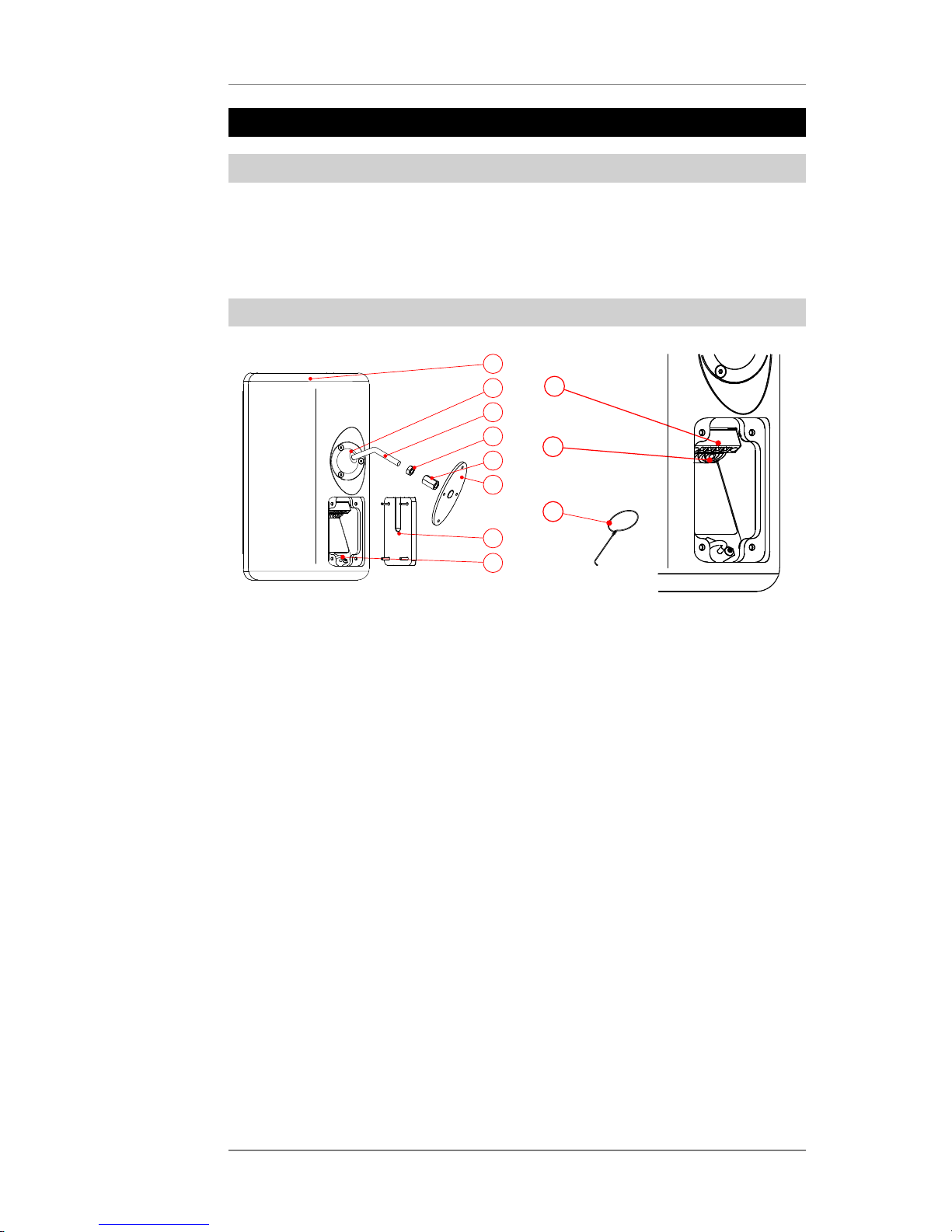
2.2 Components
1
2
3
4
5
7
8
6
10
9
11
1. Speaker enclosure, frame-reinforced birch plywood with structured finish
2. Clamp collar
3. Swivel arm with ball joint
4. Hexagon nut M10, 17 mm spanner
5. Long nut, hexagon, M10, black version: 16 mm spanner, white version: 17 mm spanner
6. Mounting plate with M10 bolt
7. Connection terminal cover with outlet for cable and safety wire
8. Safety eyelet for 5 mm quick link (quick link not included but available as accessory)
9. Phoenix connector
10. SpeakOn connectors
11. Grill dismantling tool
Page 6

User's Manual K&F SONA 6
KLING & FREITAG GMBH © 2018 Version 5.9 Page 6 of 22
3. Safety Instructions
3.1 Mounting the Speakers / Wall and Ceiling Installation
Warning
Have all installation works including suspension as well as wall or ceiling mount performed
by qualified event technicians or appropriately trained persons.
Only qualified technicians are permitted to perform the installation steps. Be sure to use
personal protective equipment at all times.
The technicians installing the speaker on site are responsible for and guarantee safe setup
and use.
Never use signal cables or power cords for suspending, aligning, or securing the systems.
Before installing, check the stability, strength, and materials of walls, ceilings, and boarding.
For example, use suitable rawlplugs for wall panels and make sure the strength is sufficient.
Be sure to tighten all bolts and screws to the specified torque.
Unless otherwise stated, use only KLING & FREITAG original parts for mounting the speakers.
Never use other parts (in particular, parts not made by KLING & FREITAG).
Make sure all fittings used are suitable for the task at hand and meet all relevant safety
requirements.
Ensure that all connections are secured against coming loose and that only authorized,
statically tested and correctly sized supports, mounting equipment, wire ropes and chains are
used.
Be sure to always visually inspect all safety-related speaker and accessory components
before use. If there are signs of wear, cracks, or deformation, etc., replace the affected parts
immediately. Visual inspection also includes checking all screwed connections of supporting
components.
The information described here does not relieve the user of the duty to follow the given
safety requirements and legal regulations.
Fixed installations (stationary):
• For fixed installations without a safety element, secure the long nut and the M10 nut
from loosening. You can do this by using threadlocking adhesives or sealants.
Mobile installations (non-stationary):
• Always secure the speaker with a second independent safety device to prevent falling.
• To do so, use an approved safety rope with a 5 mm quick link on the safety eyebolt of
the speaker enclosure. You can get an appropriate quick link available as an accessory
from KLING & FREITAG.
3.2 Instructions for Speaker Placement
Caution
Mount the speakers securely. To avoid injury or damage, always be sure to mount the
speakers securely so that they do not fall. Note that the speakers can move as a result of
vibrations. To prevent them from falling from their mounted position, they must be secured
properly. Run the cables in a way that nobody can trip over them.
The stability of stacked systems (also valid for the use of stands and distance rods!) is
contingent upon the following stability requirement:
Stacked systems may not fall over even if they are inclined by 10° in each direction. If this
requirement is not fulfilled, then it is necessary to take steps to achieve compliance. Possible
measures include strapping it to an appropriate base structure or fastening it using safety
straps.
Page 7
User's Manual K&F SONA 6
KLING & FREITAG GMBH © 2018 Version 5.9 Page 7 of 22
3.3 Preventing Hearing Damage
Caution
Keep your distance from operating speakers. This equipment is capable of delivering sound
pressure levels in excess of 90dB SPL, which may cause permanent hearing damage.
3.4 Protecting the Speakers/Reliability
Never feed audio at excessive levels to the speaker. Mixing consoles, equalizers, effect
units, etc. can produce clipping; excessive levels are normally visible on meters and through
indicators. When a power amplifier is overloaded at the output (clipping), then the amplifier
should activate a clipping warning signal. Power amplifiers can also be overloaded at the
input circuit without the amplifier signalling the clipping, i.e. when there is not sufficient
headroom in the input circuit. We, therefore, recommend turning up the power amplifiers all
the way and adjusting the level before the power amplifier in order to avoid overloading the
input circuit. In any case, be sure to lower the signal level once it sounds distorted.
Operations without CD 44 Controller:
• To protect the speakers from being destroyed and to avoid fire hazard, they should
only be operated with professional power amplifiers with a maximum rated output
power of 200 W @ 8 Ohm.
• If power amplifiers have power ratings lower than 100 W @ 8 Ohm, then it is
imperative that the amplifiers have clipping limiters. Alternately, you can also insert a
clipping limiter before the amplifier.
• To protect the loudspeaker from mechanical damage when high SPL is required a
highpassfilter of 24 dB/oct. at 60 Hz has to be inserted into the signal chain.
Operations with CD 44 Controller:
• For optimal performance and operating safety of the SONA 6 speakers we recommend
using the system controller K&F CD 44.
• When operating the loudspeaker with amplifers without clipping limiter and nominal
amplifier power less than 100 W requires to set a Limit Reduction of 3 dB for the K&F
CD 44 controller. You can find more detailed information about this option in the
K&F CD 44 hardware user's manual.
• The destruction of speakers and the risk of fire as a result of a very rare power
amplifier or speaker defect may not be avoided by the controller in any case.
For damage caused by
• overloading the speakers or
• using power amplifiers with other than the recommended maximum output power
we do not assume warranty and excludes liability for possible consequential damage.
Signals that may damage the speakers include the following:
• clipping power amplifiers
• Continuous high-volume signals at high frequencies, continuous audio feedback
• Continuously distorted signals at high levels
• Sounds occurring when connecting, disconnecting, or switching on a device on the
audio system while the speaker is on
Never place your speakers
• where they are permanently exposed to direct sunlight,
• where the devices are exposed to high moisture or rain.
• where they are exposed to strong vibrations or dust.
Page 8

User's Manual K&F SONA 6
KLING & FREITAG GMBH © 2018 Version 5.9 Page 8 of 22
Avoid damage caused by the speakers' magnetic fields
Even when not connected, loudspeakers continuously produce a magnetic field. Therefore,
during transport and placement of the speakers, it is important to ensure that there is a
sufficient distance between the speakers and magnetic data media and computer/video
monitors (except flat panels).
Page 9

User's Manual K&F SONA 6
KLING & FREITAG GMBH © 2018 Version 5.9 Page 9 of 22
4. Wall and Ceiling Installation
4.1 Required Tools
• T25 Torx key
• 16 mm spanner (only black version)
• 17 mm spanner (2 x for white version)
• Mounting accessories for installation on walls or ceilings
4.2 Temporary alignment of the speakers
Tip
Loosen one or two of the three Torx
srews only. This way you can avoid
having to tighten an screw that got
covered by the Mounting Arm while
you aligned the speaker.
Loosen this screw(s) just enough so that
you can move the Mounting Arm with
some resistance. This will simplify the
final alignment of the speaker. This
will simplify the final alignment of the
speaker.
Align the loudspeaker arm as desired, and
then retighten the Torx screws that you
previously loosened.
Tighten the screws enough so that
the speaker reliably keeps its position.
Using excessive force to tighten
the screws can result in irreparable
destruction of the threads!
Page 10

User's Manual K&F SONA 6
KLING & FREITAG GMBH © 2018 Version 5.9 Page 10 of 22
4.3 Outlet for Cable and Safety elements
To connect the speaker and attach a safety element, you must open the cover on the rear side
of the speaker.
1.
Loosen the screws on the cover on
the rear side of the speaker with a
T25 Torx key.
Remove the cover.
A
2.
Connect the safety element to the
safety eye in the speaker using the
chain quick link.
Connect the speaker via the
Speakon plug or the Phoenix
connector.
First lay the safety element and
then the speaker cable in the
feedthrough slot on the cover.
Speakon/
Phoenix
Safety
3.
Place the cover back onto the rear
of the speaker.
Mount the cover onto the rear side
of the speaker.
The speaker is now prepared for
wall, ceiling or stand mounting.
Speakon/
Phoenix
Safety
Page 11

User's Manual K&F SONA 6
KLING & FREITAG GMBH © 2018 Version 5.9 Page 11 of 22
4.4 Wall Mounting of the Speaker
Warning
If people can move freely under the hung speaker, you must secure the speaker with a safety
element. The BGV (government safety organisation) C1 can only be fulfilled when using such
a safety device. Only when this regulation has been adhered to may the speaker be hung
over people and operated.
Without this securing, the safety level corresponds to DIN 18800.
1. As an alternative to the mounting plate, you can also mount the Mounting Arm with
other suitable 10 mm bolts. Make sure that you do not extend the lever arm of the wall
mount.
Screw the mounting plate onto
the wall or ceiling using all four
mounting holes. Choose fasteners
that are suitable for the wall or
ceiling material. After installation,
the mounting plate incl. speaker
must be capable of carrying the
6-fold of its own weight. Take
suitable measures to prevent the
screw connection from loosening
itself.
2.
Attach the speaker so that the
ends of the threaded rods come in
contact.
3.
Turn the long not onto the bolt of
the mounting plate by hand until
it touches the wall plate. Tighten it
slightly using a 16 mm spanner.
4.
Screw in the counter nut M10 with
a 17 mm spanner against the long
nut while holding the long nut
tight with a 16 mm spanner.
Page 12

User's Manual K&F SONA 6
KLING & FREITAG GMBH © 2018 Version 5.9 Page 12 of 22
5.
The speaker is now completely
mounted and connected tightly to
the wall.
Now adjust the speaker.
To do so, loosen the screws at the
ball joint arm, as described on page
9.
5. Stand Installation
To mount a SONA 6 speaker on a stand, you need the accessory Stand socket M10.
1. For stand mounting, you do not need the provided long nuts. Unscrew them from the
mounting arm and keep them for possible later use.
2.
Turn the counter nut entirely onto
the thread of the mounting arm.
Place the stand adapter M10 on
the mounting arm and turn it just
before the counter nut.
3.
Screw in the counter nut M10
against the [...] using a 17 mm
spanner.
4.
Loosen the clamp screw on the
stand adapter and place the
speaker with the stand adapter
onto the top end of the stand.
Page 13

User's Manual K&F SONA 6
KLING & FREITAG GMBH © 2018 Version 5.9 Page 13 of 22
5.
Make sure that the stand pole in
the stand adapter reaches up to
behind the clamp screw.
Tighten the clamping screw.
The speaker is now securely
connected to the stand. Now adjust
the speaker.
6. Proper Alignment of the Loudspeakers
Note that precisely targeted speaker systems can significantly improve the acoustic result. It is
not possible to make generalities about the alignment of specific systems because the room
has a substantial influence on the signal and the audible result.
As a rule, the mid- and high-transducers of loudspeakers should be mounted above the
audience's face value, so that the sound distribution cannot be shadowed.
In many cases it is advisable to mount a loudspeaker higher, so that the sound will be
distributed throughout the room more evenly. Low standing systems result in a greater
difference in volume between front and back seats than higher standing systems.
To simulate the correct alignment of the speakers beforehand, there are various programs
such as ‘EASE’ or ‘Ulysses’. On the homepage www.kling-freitag.de, KLING & FREITAG
provides the simulation data for the speakers to be downloaded.
Page 14

User's Manual K&F SONA 6
KLING & FREITAG GMBH © 2018 Version 5.9 Page 14 of 22
7. Wiring
Warning
Speaker-signal currents are potentially hazardous to the human body.
When the system is in use, make sure that the connectors are secured against inadvertent
touch.
Always fully insert bared wire ends into the push connector or the Phoenix plug such that
bared parts of wire can not be touched.
For speakers with Phoenix connector the bared wire ends have to be accurately screwed into
the plugs.
7.1 Terminal assignment
Speakon connector Phoenix connector
1
-
2
-
1+
2+
+
IN
1
1 1
1
Pin 1 is parallel at all connections.
7.2 Connection diagrams
You will find all necessary pin diagrams for operations with the CD 44 Controller in the user's
manual of the CD 44! This applies for use with and without the K&F Subwoofer.
7.3 Wiring Instructions
• Before connecting your K&F SONA 6 speaker, switch off all devices and turn down all
faders and encoders.
• Be sure to use high-end speaker cables with an appropriate wire gauge. Select the wire
gauge with regard to the cable length.
• To connect the mixing console to the power-amp inputs, use shielded 2-pole balanced
microphone cables equipped with quality connectors.
• Avoid creating ground loops.
• Be sure to follow the pinouts shown in this manual.
• Check for correct polarity of the speaker links to the power amplifier. When using
amplifiers by different manufacturers, make sure the pinout is correct. If necessary,
consider modifying the amplifier or connector pinouts as required.
• Upon completing wiring, ensure that the connected speaker channels are working
in phase, for example, using a phase tester. When the connected channels are used
simultaneously, you can identify out-of-phase statuses by bass cancellation or midfrequency signals (e.g. voices) that cannot be located properly.
• When connecting multiple speakers, you can daisy-chain the signal from one speaker to
the next. Make sure that the total impedance of all speakers connected to an amplifier
does not fall below the minimum impedance specified for the amplifier. 1/R1 + 1/R2 + 1/
R3 + … = 1/Rtotal
8. Initial Operation
Page 15

User's Manual K&F SONA 6
KLING & FREITAG GMBH © 2018 Version 5.9 Page 15 of 22
• Switch off all devices and turn down all volume controls on the mixing console and the
amplifiers.
• Wire the SONA 6 systems.
• Switch on the devices in the following order: first the mixing console, then the
controller and finally the power amplifiers! Be sure to observe this power-up sequence
at all times. Failing to do so may result in switch-on noise that may damage your
system.
• If you hear noise, turn off all devices in reverse order, then check all cable connections.
• Turn up all amplifier channels one after another and output a low-volume signal to the
system. Check whether the audio is properly routed to the appropriate speakers. Make
sure no noise is heard through those speakers.
Controller operation: The SIGNAL indicators of the CD 44 controller will light when the
output level exceeds –45 dB. Your system is now ready for operation.
• With amplifiers with insufficient input-stage headroom, you may not always be able
to prevent distortion by reducing the power-amp volume controls. In this case, the
clipping indicator may not light when clipping actually occurs! To prevent damage to
the speakers, we recommend fully turning up the power-amp volume controls, then
carefully turn up the volume on the mixing console or controller or reduce the limiter
threshold of the controller as appropriate in order not to overload the amplifiers.
• When turning off the system, first turn down the amplifier input controls. Next, power
down the amplifiers, then turn off the remaining devices.
Page 16

User's Manual K&F SONA 6
KLING & FREITAG GMBH © 2018 Version 5.9 Page 16 of 22
9. Directions for the 100 volt connection.
KLING & FREITAG speakers with '100 V' option are fitted with high-quality transformers. This
serves to minimize loss of sound. Highly professional sound reinforcement results can be
achieved using '100 Volt' KLING & FREITAG speakers.
Reasons for choosing Speakers with 100 Volt Transformers:
• Reduction in conduction loss.
• Easy installation of a loudspeaker network due to simple parallel wiring. The sum of the
output power of the individual speakers (stated as VA = W) must not exceed the output
power of the 100 Volt amplifier.
• Speakers are galvanically isolated.
• Speakers can be integrated into existing 100 Volt systems.
10. Dimensions (with Mounting Arm)
228.1 mm
[8.981 inch]
120 mm
[4.724 inch]
383.4 mm
[15.093 inch]
32°
405.2 mm
[15.952 inch]
232.1 mm
[9.138 inch]
101.1 mm
[3.980 inch]
140 mm
[5.512 inch]
5 mm
[0.197 inch]
3 6 6 mm
[14 .4 0 9 inc h]
33.1 mm
[1.303 inch]
70 mm
[2.756 inch]
50 mm
[1.969 inch]
# 5.5 mm
[# 0.217 inch]
Page 17

User's Manual K&F SONA 6
KLING & FREITAG GMBH © 2018 Version 5.9 Page 17 of 22
11. Measuring Diagrams
11.1 Coverage SONA 6
Page 18

User's Manual K&F SONA 6
KLING & FREITAG GMBH © 2018 Version 5.9 Page 18 of 22
11.2 Frequency range SONA 6
Page 19

User's Manual K&F SONA 6
KLING & FREITAG GMBH © 2018 Version 5.9 Page 19 of 22
12. Technical Specifications
SONA 6
Concept 2-way passive bass-reflex system
Supported amplifiers K&F PLM+ Serie, K&F D-Serie, Lab.Gruppen IPD
2400, K&F SystemRack, K&F TOPAS, passiv at
linear Amps
Frequency range @-10 dB 65 Hz – 26 kHz (passiv)
86 Hz – 26 kHz (LCut mode)
60 Hz – 25 kHz (FR mode)
Frequency range -3 dB 80 Hz – 20 kHz (passiv)
106 Hz – 20 kHz (LCut mode)
65 Hz – 20 kHz (FR mode)
Coverage angle (nominal) 90° x 60° (hor. x vert.), rotatable CD-Horn
Power rating 100 watts
Program load 200 watts
Peak load 400 watts
SPL (1 m, max.) 118 dB (SPL Peak/1 m)
Nominal impedance 8 Ohm
Speakers / channels see matrix
Components 8" low-mid chassis,
1" compression driver with 45 mm
Titanium diaphragm
Connection 2 x Speakon 4-pol. NL4MP (1+/1-),
1 x Phoenixbuchse (parallel)
Enclosure
Design enclosure out of Multiplex, highly
resistant structure paint (PU) in black or white,
safety eyelet for quick chain link, ball joint
mounting arm (104 mm) with mounting plate,
sunk-in, to the bottom faced and concealed
connectors, exchangeable front grille, rotatable
logo
Dimensions (H x W x D) 195 x 366 x 232 mm
Weight 6.8 kg
Color RAL 9005 (black) oder RAL 9010 (white)
Optional '100 Volt' with 10/20/40 VA toroidal transformer
(13.9 kg), 'special finish in RAL colours'
Page 20

User's Manual K&F SONA 6
KLING & FREITAG GMBH © 2018 Version 5.9 Page 20 of 22
13. EC Declaration of Conformity
Manufacturer: Kling & Freitag GmbH
Junkersstraße 15
30179 Hannover
Germany
Representative authorized for compiling
the technical documentation:
Kling & Freitag GmbH
Abt. Entwicklung
+49 511 96997-50
Deutschland
Product: K&F SONA 6 speaker system
We declare that the designated product(s) are in conformity with the protection
requirements imposed by the following EU directives:
• 2004/108/EG, Electromagnetic Compatibility (EMC) Directive
• 2006/95/ECC, Low Voltage Directive
• VDE 0042-12/2013-02 Technical documentation for the assessment of electrical and
electronic products with respect to the restriction of hazardous substances
Hannover, 09 November 2017
Jürgen Freitag
(Managing Director / CEO)
Page 21

User's Manual K&F SONA 6
KLING & FREITAG GMBH © 2018 Version 5.9 Page 21 of 22
14. Accessories
• 5 mm chain quick link, stamped. For use with the safety eye on the speaker.
• K&F Stand Adapter, M10
15. Disposal
Please recycle the packaging material of the device.
15.1 Germany
Don’t dispose of waste electrical equipment through household waste.
Don’t deliver it to official recycling points either.
All KLING & FREITAG products are plain business-to-business (B2B) products. Therefore,
KLING & FREITAG GmbH is exclusively responsible for disposing of all KLING & FREITAG waste
equipment marked with a crossed-out garbage-can icon. Please call the below phone number
when you have a KLING & FREITAG product (marked with the crossed-out garbage-can icon)
for disposal. We will offer you a straightforward and professional disposal at no cost.
KLING & FREITAG equipment with no such icon was distributed before 24 March 2006; in
that case, the owner is legally responsible for disposal. We will, however, gladly assist you by
naming appropriate ways of disposal.
For further disposal information of KLING & FREITAG waste products, call +49 511 -96 99 7 -0
Explanation: The Electrical and Electronic Equipment and Appliances Act (ElektroG) is the
German implementation of the European (EU) Waste Electrical and Electronic Equipment
Directive (WEEE, 2002/96/EC).
Therefore, starting on 24 March 2006, KLING & FREITAG GmbH has marked all products
subject to the WEEE that are distributed in Germany with an icon showing a crossed-out
garbage can with a white bar below it. The icon indicates that the equipment was distributed
on or after 24 March 2006 and must not be disposed of through household waste.
KLING & FREITAG GmbH is legally registered as a manufacturer with the German wasteequipment registration authority (EAR). The WEEE registration number is: DE64110372.
We substantiated towards the EAR that our products are for B2B trade only.
15.2 EU, Norway, Iceland, and Liechtenstein
Don’t dispose of waste electrical equipment through household waste.
Starting on 13 August 2005, KLING & FREITAG GmbH has marked all products subject to the
WEEE directive that are distributed in any member state of the European Union (except
Germany), Norway, Iceland, or Liechtenstein with an icon showing a crossed-out garbage can
with a white bar below it.
This sign indicates that the disposal on domestic waste is prohibited and that the product has
been put into circulation on 08/13/2005 at the earliest.
Unfortunately, the European WEEE directive was implemented in different national
legislation in the EU member states, making it impossible to offer a consistent disposal
solution throughout Europe.
The local distributor (sales partner) in the respective country is responsible for complying with
the applicable legislation.
Contact your retailer or the local authorities for information on the regulations applicable in
any EU member state (except Germany).
15.3 All Other Countries
Contact your retailer or the local authorities for information on the regulations applicable in
any country not listed above.
Page 22

User's Manual K&F SONA 6
KLING & FREITAG GMBH © 2018 Version 5.9 Page 22 of 22
INDEX
• 100 V............................................................................................................................................ 16
• Accessories................................................................................................................................... 21
• Alignment................................................................................................................................. 9,13
• Components...................................................................................................................................5
• Connection diagrams..................................................................................................................14
• Dimensions...................................................................................................................................16
• Disposal........................................................................................................................................ 21
• EC Declaration of Conformity....................................................................................................20
• I/O................................................................................................................................................. 14
• Initial Operation..........................................................................................................................14
• Items Included............................................................................................................................... 5
• Measuring Diagrams...................................................................................................................17
• Mounting....................................................................................................................................... 9
• Product Description.......................................................................................................................5
• Safety Instructions.........................................................................................................................6
• Speaker-stand.............................................................................................................................. 12
• Technical Specifications...............................................................................................................19
• Tool.................................................................................................................................................9
• Wiring...........................................................................................................................................14
 Loading...