

Page 1

Self Powered LINE 212-6 - SP / LINE 212-9 - SP
Benutzer Handbuch
User's Manual
Important Information,
Wichtige Informationen,
Please Read Before Use!
vor Inbetriebnahme lesen!
KLING & FREITAG GmbH
KLING & FREITAG GmbH
Junkersstrasse 14
Junkersstrasse 14
D-30179 Hannover
D-30179 Hannover
PHONE 0 (049) 511- 969 97-0
TEL 0 (049) 511- 969 97-0
FAX 0 (049) 511- 67 37 94
FAX 0 (049) 511- 67 37 94
www.kling-freitag.de
www.kling-freitag.de
Released: 09.09.2014
Version 5.1
Page 2

User’s Manual LINE 212-6 - SP / LINE 212-9 - SP
KLING & FREITAG GMBH ©2003 - 2014 Version 5.1, 09.09.2014 Page 2 of 44
Page 3

User’s Manual LINE 212-6 - SP / LINE 212-9 - SP
Thank you for your decision to buy a Kling & Freitag product. To guarantee a troublefree operating of the equipment and to allow the KLING & FREITAG --- ‘SP’ speaker
system to achieve its full potential please read the operating instructions carefully
before use.
With the purchase of a LINE 212 --- SP system with integrated power amplifier technology, you have acquired a speaker system with the highest possible quality and
performance capabilities.
As the owner of this system, you now have a versatile and highly professional tool
which, when operated properly, is a true pleasure to use.
Symbols in User's Manual
This symbol indicates the possibility of life-threatening danger and a
health risk for persons. Not following these instructions may result in
serious health problems including potentially fatal injuries.
Warning
This symbol indicates a possibly dangerous situation. Not following
these instructions may cause minor injuries or cause property damage.
Caution
This symbol gives instructions for the proper use of the described products. Not following these instructions may cause malfunctions or property damage.
Important
Information about this User's Manual
User's Manual K&F LINE 212-6 - SP / LINE 212-9 - SP, Version 5.0, 09.09.2014
© by André Figula, Kling & Freitag GmbH, 2003 - 2014; all rights reserved.
All specifications in this manual are based on information available at the time of pub-
lishing for the features and safety guidelines of the described products.
Technical specifications, measurements, weights and properties are not guaranteed.
The manufacturer reserves the right to make product alterations within legal provisions
as well as changes to improve product quality.
All persons who use the speaker system must have this guide and all further
information for safe operations available to them during assembly, disassembly, and use.
We appreciate any input with suggestions and improvements for this manual.
Please send this to us at the following address:
info@kling-freitag.de or to:
KLING & FREITAG GMBH, Junkersstr.14, D-30179 Hannover
Phone +49 (0) 511 - 96 99 70, Fax +49 (0) 511 - 67 37 94
KLING & FREITAG GMBH ©2003 - 2014 Version 5.0, 09.09.2014 Page 3 of 44
Page 4

User’s Manual LINE 212-6 - SP / LINE 212-9 - SP
Contents
Chapter Page
1. General Safety Instructions 5
2. Introduction SP Loudspeakers 7
3. Connectors, Controls und Displays 9
4. Power Cord 13
5. Rigging Instructions for Line 212 Systems 14
5.1 Vertical Suspension 14
5.2 Horizontal Suspension 15
6. Using the ‘allsafe JUNGFALK’ Flying Points 16
7. Using the Rear Mounted ‘allsafe JUNGFALK’ Flying Track 17
7.1 Mounting the Single Stud Fittings 17
7.2 Mounting the Double Stud Fitting 18
8. Coverage Pattern of the Line 212 --- SP Systems 19
8.1 Changing the Coverage Pattern 19
9. Mounting Instructions for Speakers 20
9.1 Proper Arrangement of the Loudspeakers 20
9.2 Arrayed Speaker Systems (Cluster) 21
9.3 LINE 212 Systems on Top of SW 215E 22
10. Wiring 23
10.1 Avoiding Ground Loops 23
10.1.1 What is a Ground Loop? 23
10.1.2 Avoiding Ground Loops 23
10.2 Connecting the Power Connectors to the Connecting Terminal 24
11. Configurations and Connecting Diagrams 25
11.1 Operating the Systems without K&F System Controller 25
11.1.1 Full-Range Mode 25
11.1.2 Full Range Mode with Subwoofer 26
11.2 Operating the Systems with K&F System Controller 27
11.3 Maximum Configuration 27
12. Operating the Speakers 28
13. Touching Up Damage to Paint / Changing the Front Foam 28
14. Block Diagram LINE 212 - SP 29
15. Technical Specifications 30
15.1 LINE 212-6 - SP 30
15.2 LINE 212-9 - SP 32
16. Measuring Charts 33
16.1 LINE 212-6 - SP 33
16.2 LINE 212-9 - SP 35
17. Dimensions 37
18. Accessories for the LINE 212 System 38
19. Regulations for Disposal 39
19.1 Germany 39
19.2 EU, Norway, Iceland, and Liechtenstein 39
19.3 Other Countries 39
20. Declaration of Conformity and International Certificates 40
20.1 Declaration of Conformity 40
20.2 EMV Certificate Directive 89 / 336 / EWG 41
20.3 TÜV Certificatefor USA und Canada (UL 6500) 43
21. Included Instructions for Loudspeakers and Mounting Accessories
KLING & FREITAG GMBH ©2003 - 2014 Version 5.1, 09.09.2014 Page 4 of 44
Page 5

User’s Manual LINE 212-6 - SP / LINE 212-9 - SP
CAUTION
1. General Safety Instructions
Risk of electric shock!
Do not open the units!
Warning: To avoid electric shock hazard, do not expose this
appliance to rain or moisture. The enclosures may only be
opened by qualified personnel!
Do not install devices in any of the following places:
− where the devices are permanently exposed to direct sunlight.
− near any heat sources and open fire. Do not put candles etc. on top of the speaker.
− where the airflow for cooling is blocked. A minimum distance of 10 cm to the heat
sink on the rear of the speaker must be kept.
− where the devices are exposed to high moisture. Objects filled with liquids, such as
a vase, must not be placed on the speaker.
− where the devices are exposed to strong vibrations and dust.
Power supply
Before connecting the AC power cable of the SP speaker, please check if the available
Warning
voltage is compatible with the operating voltage as indicated on the unit. If this is not
the case, then the unit needs to be adapted by the manufacturer or an authorized service centre. If the unit is not compatible with the available voltage, it should never be
connected! This could irreparably ruin the SP speaker.
Make sure that the power outlet supplies a ground connector, which must be connected to the unit via the PE conductor of the power cord!
All equipment, which is connected together using signal cables and has a connection to
protective earth, must be connected to a common PE conductor. If not, there is a risk of
an electric shock or the destruction of the connected equipment.
The power plug must always be used to disconnect from the power supply. Furthermore, the power plug must be easily accessible for use at all times.
Protection of electrical cables
Power cords should be laid in such a way that they are protected against footstep damages, tensile strain and against being trapped.
Transportation
When transporting the equipment, make sure that it is protected from vibrations.
Cleaning
The equipment should only be cleaned with a damp cloth when it is not plugged in.
Pauses in use
The power cord should be disconnected from the power source during longer pauses in
use.
Intrusion of objects or liquids
No objects or liquids should intrude or leak into the equipment.
KLING & FREITAG GMBH ©2003 - 2014 Version 5.0, 09.09.2014 Page 5 of 44
Page 6

User’s Manual LINE 212-6 - SP / LINE 212-9 - SP
Maintenance and technical service
The user should not perform any maintenance work on the equipment other than that
which is described in this manual. Repairs should be executed by a qualified service
technician only.
In the following cases, the unit should be serviced by an authorized technician only if:
− the power cord or the mains connectors have been damaged.
− objects or liquids have gotten into it.
− it was exposed to rain.
− it doesn't appear to be functioning properly.
− it has fallen down or the enclosure is damaged.
Warning
Mounting the speakers
If the weight of the speaker exceeds 25 kg then it is necessary for two people to carry it.
To prevent injury, this equipment must be securely placed on the floor or secured to the
wall according to the mounting instructions. Speakers, which are stacked, must be secured with securing straps. Please note that speakers can move as a result of vibrations.
To prevent them from falling from their mounted position, they must be secured
properly.
Speakers may only be suspended by qualified personnel.
Never use signal cables or power cords for suspending, aligning or securing the systems.
When laying the connecting cables, make sure that nobody can trip.
The speakers must be hung by using at least two of the designated flying points. The
same applies when lifting and aligning the speakers.
Never hang more than two speakers under one another without using the designated
Kling & Freitag rigging equipment.
Ensure that all installation connections comply with the applicable safety guidelines and
that the size and strength are sufficient. Further instructions are in our user's manual for
assembly equipment and in the general safety instructions for speakers and assembly
equipment.
For mobile and fixed installations, use only rigging equipment from KLING & FREITAG.
Make sure to observe the included safety and mounting instructions for loudspeakers
and accessories.
Unwanted interference
RF interference on the power cord or on the line signal cables may lead to unwanted
sound interference.
Damage caused by the speakers' magnetic fields
Speakers are permanently surrounded by a magnetic field, even when they are not operating. Therefore, during transport and placement of the speakers, it is important to
ensure that there is always approx. 1 m between the speakers and magnetic data media
and computer/video monitors.
The following signals may damage the speakers
− permanent high-pitched signals with high frequency and continuous noise from
feedback.
− permanently distorted signals with high power.
− noises, which occur when the SP speaker is connected while equipment is being
connected, disconnected or switched on.
Preventing hearing damage
To prevent the risk of hearing damage, avoid being too close to operating speakers,
even if the volume level seems to be low enough. In general, volume levels over 90 dB
can cause hearing damage.
Important
Caution
KLING & FREITAG GMBH ©2003 - 2014 Version 5.1, 09.09.2014 Page 6 of 44
Page 7

User’s Manual LINE 212-6 - SP / LINE 212-9 - SP
2. Introduction SP Loudspeakers
‘SP’ denotes the ‘Self Powered’ product line in the K&F range of loudspeakers. Based
on selected K&F speaker systems, the ‘SP’ models are equipped with state-of-the-art
integrated driver circuits and Class D power amplifier technology. The extremely
lightweight system electronics replace ponderous racks, power amplifiers, controllers,
and speaker cables.
Aside from the integrated power amplifier and input modules with controller functions, the full-range systems possess a passive crossover so that the advantageous
features provided by the K&F passive technology (all-pass filter, protection circuits)
remain usable. The frequency separation for the subwoofers is controlled by an active
110 Hz low-pass filter.
Integrated phase optimisation allows for all systems in the ‘SP Series’ to be combinable with one another. With this, the ‘SP’ speakers, when the filter section is switched
off, have a completely comparable sound to the corresponding versions without integrated power amplifier technology. Operations using a K&F System Controller CD 44,
CD 24 (discontinued) and C2 (discontinued) are also possible, which is appropriate for
many applications.
Operating the ‘SP Series’ is incredibly easy: The full-range systems reproduce the complete frequency spectrum. If necessary, the ‘SP’ subwoofers in parallel operations can
provide an additional bass boost.
The Input Module
− Line signal input
− Limiter section (feed-forward RMS-limiter and peak limiter in feed-back design).
− High pass filter, 45 Hz tops, and 32 Hz subwoofers
− Low pass filter 110 Hz (only subwoofer systems)
− System specific, switchable frequency deemphasis (‘FILTERS ON/ OFF’) controllable
by a covered switch on the connecting terminal
− Phase correction
− Level adjustment (countersunk level control on the connecting terminal)
The Amplifier Module
− 1 x, or 2 x 1 kW Class D state-of-the-art power amplifier
− Minimal dimensions (speaker dimensions of the models without the ‘SP’ module are
retained)
− Low weight (weight increase of 2.5 / 4 kg as compared to systems without the ‘SP’
module; and with the Line 212 --- SP, the weight even stays identical)
− High efficiency enables convection cooling, because of which bothersome fans are
unnecessary
− High fidelity (even in high frequency range) and a large power bandwidth resulting
from impedance optimisation
KLING & FREITAG GMBH ©2003 - 2014 Version 5.0, 09.09.2014 Page 7 of 44
Page 8

User’s Manual LINE 212-6 - SP / LINE 212-9 - SP
Modes of Operation
− Operations without external controller:
with activated filters (FILTERS ‘ON’), all K&F models in the ‘SP Series’ are combinable with one another by simply linking the signal from one speaker to the next.
− With optional K&F System Controller*:
via a K&F System Controller CD 44, CD 24 (discontinued) or C2 (discontinued,
with system plug-in card) or an Audio DSP*
− if used with BSS Soundweb, FDS 366, 336, 334, and XTA DP 226, 224, K&F sys-
tem parameters are available upon request
* The operation of the K&F ‘SP’ models with K&F System Controller or Audio DSP is
recommended for uses in which special filter presets are advisable, i.e. in combination
with passive systems of the ‘CA Series’, in cluster operations (top low cut), when bass
and high boost are necessary, adjustment to the room acoustics (EQ), etc.
The following K&F ‘SP’ speakers are available:
Full-range systems: CA 1001 - SP,
CA 1201 - SP,
CA1215-6 - SP, CA 1215-9 - SP
CA 1515-6 - SP, CA 1515-9 - SP
LINE 212-6 - SP, LINE 212-9 --- SP
Subwoofers: SW 112 - SP, SWi 112 - SP,
SW 115D - SP, SWi 115D - SP,
SW 118E - SP, SWi 118E - SP,
SW 215E - SP
KLING & FREITAG GMBH ©2003 - 2014 Version 5.1, 09.09.2014 Page 8 of 44
Page 9

User’s Manual LINE 212-6 - SP / LINE 212-9 - SP
3. Connectors, Controls und Displays
1
2
3
4
Warning
5
6
7
8
1) LINE IN and LINE OUT (+6 dB)
Electronically balanced input and output connectors. Use the XLR female connector
(marked ‘IN’) as input. The parallel-wired XLR male connector (‘OUT’) is for connection to further ‘SP’ loudspeakers.
2) GROUND LIFT
When the ‘Ground Lift’ switch is set to LIFT, pin 1 of the LINE IN connector (ground)
is not connected to the chassis ground of the integrated amplifier module. The
ground connection between LINE IN (XLR male) and LINE OUT (XLR female) is maintained. The use of the ‘Ground Lift’ switch is sometimes necessary in dealing with
hum problems (see chapter 10.1 )
Never tape over the protective earth on the plug
Never tape over the protective earth on the plug ---
Never tape over the protective earth on the plug Never tape over the protective earth on the plug
3) PROTECTIVE COVER
--- danger to life!
danger to life!
------
danger to life!danger to life!
The protective cover prevents unwanted adjustment of the gain control and filter
ON / OFF switch. The cover has a snap-in lock. In order to reach the controls beneath, turn the cover sharply down in the direction of the arrow.
KLING & FREITAG GMBH ©2003 - 2014 Version 5.0, 09.09.2014 Page 9 of 44
Page 10

User’s Manual LINE 212-6 - SP / LINE 212-9 - SP
4) GAIN CONTROL (± 6 dB)
a) The gain control can be used to adjust the input level of the amplifier module
by ± 6dB. It serves to balance the volume levels of the various systems. In order to avoid overloading the input circuit or mixer’s output circuit, it should
normally be set in the case of K&F full-range systems at 0 dB (centre notch
setting).
b) When operating with K&F System Controller, set the input level of the ampli-
fier module on the controller (Input Gain). The gain control on the SP speaker
should be set at 0 dB (centre notch setting). One exception to this rule is a
cluster arrangement, in which the inner speakers should be set at a lower level than the outer ones. In this case, the level of the gain control on the inner
SP speakers can be adjusted downwards accordingly.
When operating with additional bass systems it is very important that the respective volume levels between the top speakers and the bass systems are correctly
balanced. To this end, the sound engineer should check the volume levels during
the set-up and adjust them accordingly. When setting up a system without a K&F
System Controller this adjustment should be carried out using the gain control of
the SP subwoofer; in the case of a system with K&F System Controller, set the
gain on the controller.
Normally we recommend the following settings*
Configuration:
Configuration: Gain control
Configuration:Configuration:
+
+
+
* These details may vary due to different room geometries. The position of a bass
speaker is also crucial for its actual sound level. A bass speaker, which is on the
floor, can be a few decibels louder than a flown bass system because of the floor
reflections. Because of this, a sound engineer must always fine-tune the system using the corresponding level controls.
or
or
Gain control
Gain controlGain control
Line 212:
---- 6 dB
6 dB
6 dB6 dB
Subwoofer:
+6 dB
+6 dB
+6 dB+6 dB
Line 212:
0 dB
0 dB
0 dB0 dB
Subwoofer:
+6 dB
+6 dB
+6 dB+6 dB
Line 212:
0 dB
0 dB
0 dB0 dB
Subwoofer:
0 dB
0 dB
0 dB0 dB
KLING & FREITAG GMBH ©2003 - 2014 Version 5.1, 09.09.2014 Page 10 of 44
Page 11

User’s Manual LINE 212-6 - SP / LINE 212-9 - SP
5) FILTERS ON / OFF (High Pass / Low Pass / Equalizer)
This switch turns the filter in the SP module on (‘ON’), or off (‘OFF’).
a) The switch should always be in the ‘ON’ position when the speakers are being
driven without K&F System Controller.
b) The switch should always be in the ‘OFF’ position when the speakers are being
driven with K&F System Controller.
The filters consist of:
− high-pass: protects the speakers against mechanical stress due to frequen-
cies outside the speaker's frequency range (protection against subsonic
frequencies)
− EQ: filter for basic equalization, optimising the frequency response of the
speaker systems.
Furthermore, the SP filter module has a phase alignment, which prevents loss
of certain frequencies due to phase shift between mid-high and bass systems.
Thus the combination of all available K&F mid-high SP systems with all K&F
bass SP systems is possible, and 100% phase compatibility with all K&F speakers operating in conjunction with a K&F System Controller in the ‘2-way active’
mode is guaranteed.
6) LED POWER ON (GREEN) and LIMIT / PROTECT (RED)
The LED is dual-purpose:
a) When the LED is green, the speaker is connected to the supply voltage and
ready for operation
b) The LED will turn red if…
…the input signal is so high that the internal limiters reduce its level.
The limiters consist of a peak limiter, which limits the peaks of the signal,
and an RMS / thermal limiter, which continuously regulates excessive levels.
During normal operation, the red light may occasionally illuminate briefly
when the barely audible limiter cuts in to limit peak levels. It does indicate
that the level peaks are limited by the limiter circuit. The peak performance
of the speaker has then been reached.
Should the red light come on more frequently or remain illuminated, the
output level of the mixer should be reduced. When speakers with and
without SP module are in operation simultaneously, the gain control on the
SP speaker can be turned down, provided the level is sufficient for the other power amplifiers. The limiter protects the speaker from damage due to
excessive levels.
KLING & FREITAG GMBH ©2003 - 2014 Version 5.0, 09.09.2014 Page 11 of 44
Page 12
User’s Manual LINE 212-6 - SP / LINE 212-9 - SP
Fault
Measure
Function
LED remains red or flickers
Reduce output level on mixer until the
nal, LED shows red in spite
duced mixer output
Allow to cool. The amplifier module
switches itself on after a few minutes.
Temperature
ed after
Output signal is too low, no
bass frequencies or no high
c) The LED stays permanently red, if…
…the protection circuitry of the integrated power amplifier cuts in and as a
result, no further signal reaches the speaker (Protect Mode).
The protection circuitry switches off the integrated power amplifier,…
− …if the temperature of the amplifier module is too high. As soon as
the temperature falls below the critical value, the amplifier module is
switched on again automatically. Excessive temperatures can be
caused for example by inadequate ventilation of the heat sink. Make
sure that the heat sinks are not covered or positioned directly against a
wall.
− …if the output impedance is too low or in the case of a short circuit,
caused for example by a defective chassis or a faulty component on
the crossover.
− …if the amplifier has an internal fault. The SP amplifier module checks
that all is functioning correctly during operation. As soon as a fault becomes apparent, the module switches into protect mode. If only one
module has a fault, the input signal is attenuated by 70 dB, to prevent
damage to the other module.
Measures to be taken when LED is red:
Limiter
continually during operation.
LED goes out or flickers only occasionally
No or too low output sig-
protection
of re
Provide sufficient ventilation.
level.
No or too low output signal, LED stays r
Have loudspeaker checked by
authorized service technician.
Other
protection
cooling down.
Have loudspeaker checked by
authorized service technician.
Other
protection
frequencies.
7) AC MAINS ‘IN’
Connect this PowerCon socket using the mains cable supplied to a max. 16 A fused
mains socket, paying particular attention to the stated mains voltage! Connection
to an incorrect mains voltage can result in irreparable damage!
8) AC MAINS ‘OUT’
Socket for connection to further equipment such as further speakers with SP module. Use only connection cables, which conform to your national safety regul
Use only connection cables, which conform to your national safety regula-
Use only connection cables, which conform to your national safety regulUse only connection cables, which conform to your national safety regul
tions.
tions.
tions.tions.
Maximum power consumption: 230 V: 10 A / 2300 W
110 V: 10 A / 1150 W
a-
a-a-
Important
Warning
KLING & FREITAG GMBH ©2003 - 2014 Version 5.1, 09.09.2014 Page 12 of 44
Page 13

User’s Manual LINE 212-6 - SP / LINE 212-9 - SP
4. Power Cord
In Germany, a pre-constructed ready for use power cord is included in the delivery.
For deliveries to foreign countries, a pre-constructed power cord incl. PowerCon plug is
included. Because of the different standards abroad, the power plug is not included.
This must be subsequently assembled only by qualified electrical specialists.
brown = BN = L
green / yellow = GNYE =
blue = BU = N
KLING & FREITAG GMBH ©2003 - 2014 Version 5.0, 09.09.2014 Page 13 of 44
Page 14
User’s Manual LINE 212-6 - SP / LINE 212-9 - SP
5. Rigging Instructions for Line 212 Systems
The speakers may only be mounted by trained specialised pe
The speakers may only be mounted by trained specialised perrrrsonnel with proof
The speakers may only be mounted by trained specialised peThe speakers may only be mounted by trained specialised pe
of their qualifications as an e
of their qualifications as an experienced ‘rigger’.
of their qualifications as an eof their qualifications as an e
Please follow the accompanying instructions for speakers and assembly equipment.
Please follow the accompanying instructions for speakers and assembly equipment.
Please follow the accompanying instructions for speakers and assembly equipment.Please follow the accompanying instructions for speakers and assembly equipment.
xperienced ‘rigger’.
xperienced ‘rigger’.xperienced ‘rigger’.
sonnel with proof
sonnel with proof sonnel with proof
Ensure that all connections are secured to prevent their detaching on their own and that
only admissible statically tested and sufficiently sized connecting devices, ropes and
chains are used.
Warning
Pay attention to the required safety factors. Please follow the accompanying safety and
mounting instructions carefully.
A maximum load of 73 kg may be suspended from the two flying points of one Line
212 system. This
JUNGFALK’ flying point.
This means a maximum additional load of 36.5 kg on each
means a maximum additional load of 36.5 kg on each ‘allsafe
ThisThis
means a maximum additional load of 36.5 kg on each means a maximum additional load of 36.5 kg on each
flying point. This applies for both vertical (see details on this page) and
flying point.flying point.
horizontal suspension (see details on next page).
5.1 Vertical Suspension
The Line 212 System must always be mounted
with two wire ropes or chains, which are independent of one another! Furthermore, the systems, no matter if individual or connected to
one another, must be secured onto the ‘allsafe
JUNGFALK’ flying track on the rear. This safety
rope may be used for aligning the systems.
The safety rope must have a minimum length
The safety rope must have a minimum length
The safety rope must have a minimum length The safety rope must have a minimum length
of 100 cm and must be attached so that, in
of 100 cm and must be attached so that, in
of 100 cm and must be attached so that, in of 100 cm and must be attached so that, in
case it falls, the height of the fall is kept to a
case it falls, the height of the fall is kept to a
case it falls, the height of the fall is kept to a case it falls, the height of the fall is kept to a
minimum. A possible fall height of 20 cm may
minimum. A possible fall height of 20 cm may
minimum. A possible fall height of 20 cm may minimum. A possible fall height of 20 cm may
not be exceeded! With a higher fall height,
not be exceeded! With a higher fall height,
not be exceeded! With a higher fall height, not be exceeded! With a higher fall height,
the dyna
the dynamic load of a fall could be inadmiss
the dynathe dyna
bly high; potential risk of system crash.
bly high; potential risk of system crash.
bly high; potential risk of system crash.bly high; potential risk of system crash.
mic load of a fall could be inadmissi-
mic load of a fall could be inadmissmic load of a fall could be inadmiss
i-
i-i-
The safety ropes of different systems must always come together at one point.
Each of the utilised separate lifting accessories
(chains / wires / shackles) must be able to carry
the 12-fold load of the total weight.
While installing, be sure that the system can
swing in case a rigging point fails. With this in
mind, the speaker must be mounted so that no
people or objects are within the potential range
of the swinging speakers.
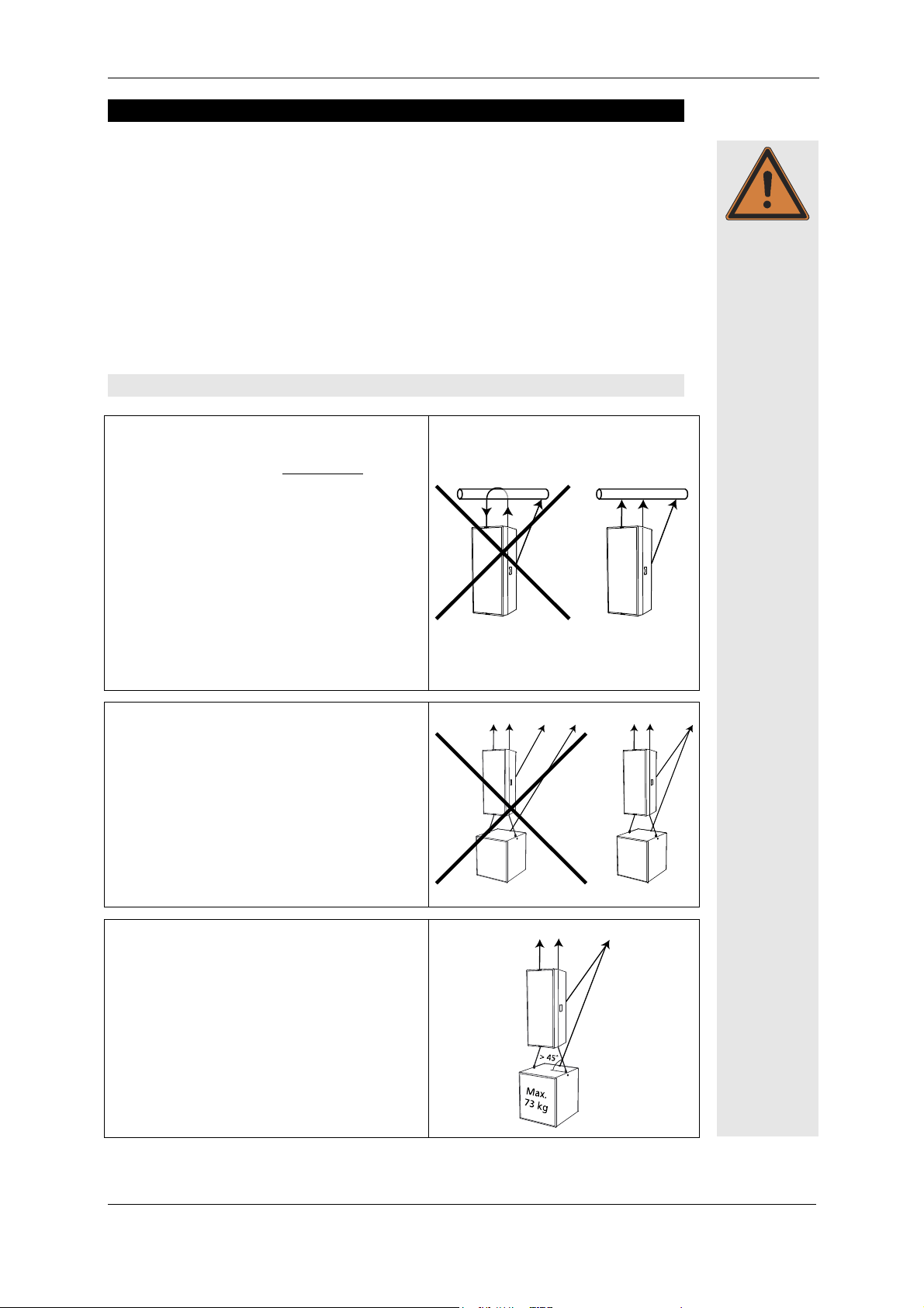
The weight of the speaker hung below may not
exceed 73 kg (this weight corresponds to the
approx. weight of a SW 215E-SP).
The angle of the rope / chain to the top of the
speaker mounted below may not exceed 45°.
KLING & FREITAG GMBH ©2003 - 2014 Version 5.1, 09.09.2014 Page 14 of 44
Page 15

User’s Manual LINE 212-6 - SP / LINE 212-9 - SP
5.2 Horizontal Suspension
If a speaker unit consisting of several connected systems is to be
flown and aligned, then the individual speakers must be attached
to one another before connecting them to the ‘allsafe JUNGFALK’
Warning
Flying Track. Consult the provided illustration when doing so. For
the rear connection of the loudspeaker systems, use the double
stud fittings available from Kling & Freitag and a proven 1/2"
shackle (alternative single stud fittings and 3/8" shackle). Pull the
threaded bolt of the shackle with a torque of 10 Nm (hand
with 200 mm long lever, e.g. screwdriver).
with 200 mm long lever, e.g. screwdriver). Alternatively, you
with 200 mm long lever, e.g. screwdriver).with 200 mm long lever, e.g. screwdriver).
can use proven, high
can use proven, high----strength shackles with a cotter pin
can use proven, highcan use proven, high
in this way can you ensure that the bolt will not become loose.
The ‘allsafe JUNGFALK’ flying track can only support weights up
to 73 kg. Therefore, the load must be distributed on several flying tracks when suspending the systems.
For horizontal operations, the system is designed for a maximum array of three Line
212-6 systems. More of theses systems may not be flown below one another.
strength shackles with a cotter pin.... Only
strength shackles with a cotter pinstrength shackles with a cotter pin
(hand----tight
tight
(hand(hand
tight tight
Alternatively, you
Alternatively, you Alternatively, you
We recommend using the BGV C1 certified and type tested Click & Fly Rigging
System for mounting the Line 212 systems (see the ‘Click & Fly for Line 212 /
SW215E' user's manual).
Please follow the following instructions for flown operations without the Click
& Fly Rigging System:
Wrong:
− The upper rigging points of the top speaker
must carry the full load. Consequently, the
permissible max. load of the top points is exceeded.
− The speakers are not secured by the additional
safeties.
Right:
− The load of the individual speakers is threaded
through the bent continuous bracket. The load
is, therefore, held by the bracket and the
speakers’ flying points consequently only have
to carry the load of the corresponding speaker.
− The speakers are connected to one another on
the rear. The suspension point is located on the
connection of the two lower speakers. As a result, the load is distributed to both speakers.
KLING & FREITAG GMBH ©2003 - 2014 Version 5.0, 09.09.2014 Page 15 of 44
Page 16

User’s Manual LINE 212-6 - SP / LINE 212-9 - SP
6. Using the ‘allsafe JUNGFALK’ Flying Points
Single Stud Fitting
Used as fastener to the ‘allsafe
JUNGFALK’ Flying Point.
1.)
Take the single stud fitting in one
hand...
3.)
‘allsafe JUNGFALK’ Flying Point
Receptacle for special fasteners.
2.)
... and push the locking device up
against the spring tension.
4.)
Put the flat head of the holding
bolt into the guiding of the flying
point.
Release the locking device when
the single stud fitting is located in
the middle of the flying point.
Make sure that the locking device
clicks into place.
5.)
Warning
Check that the single stud fitting is
securely fastened and cannot be
pulled out.
KLING & FREITAG GMBH ©2003 - 2014 Version 5.1, 09.09.2014 Page 16 of 44
Page 17

User’s Manual LINE 212-6 - SP / LINE 212-9 - SP
7. Using the Rear Mounted ‘allsafe JUNGFALK’ Flying Track
The ‘allsafe JUNGFALK’ flying track can be used for fixing and adjusting the speaker systems.
The ‘allsafe JUNGFALK’ flying track can only support weights
up to 73 kg!
Please also consult the provided instructions for speakers and
assembly equipment.
Warning
7.1 Mounting the Single Stud Fittings
Single Stud Fitting
Used as fastener to the ‘allsafe
JUNGFALK’ Flying Point and the
‘allsafe JUNGFALK’ Flying Track.
1.)
Take the single stud fitting in one
hand...
3.)
2.)
4.)
‘allsafe JUNGFALK’ Flying Track
Receptacle for special fasteners such
as the single stud fitting.
... and push the locking device up
against the spring tension.
Warning
KLING & FREITAG GMBH ©2003 - 2014 Version 5.0, 09.09.2014 Page 17 of 44
Slide the flat head of the holding
bolt into the guiding device of
the flying track and slide the single stud fitting sideways into the
flying track.
Release the locking device when the
single stud fitting is located over the
tabs of the track. Make sure that the
locking device clicks into place. Make
sure that it is secured tightly.
Page 18

User’s Manual LINE 212-6 - SP / LINE 212-9 - SP
7.2 Mounting the Double Stud Fitting
Double Stud Fitting
Used as fastener to the ‘allsafe
JUNGFALK’ Flying Point and the
‘allsafe JUNGFALK’ Flying Track.
‘allsafe JUNGFALK’ Flying Track
Receptacle for the double stud fitting.
1.)
Align the double stud fitting as
shown above and push it into the
track,…
2.)
... slide the pushed double stud fitting
to the middle of the speaker until it
clicks into place. Make sure that it is
secured tightly.
Warning
KLING & FREITAG GMBH ©2003 - 2014 Version 5.1, 09.09.2014 Page 18 of 44
Page 19

User’s Manual LINE 212-6 - SP / LINE 212-9 - SP
8. Coverage Pattern of the Line 212 --- SP Systems
The Line 212 can be operated in a vertical or horizontal position. The coverage pattern
of the speaker can be adapted to special needs by a 90° rotatable horn.
The following graphics demonstrate how to recognize how the built-in horn emits in a
standing speaker: To determine the coverage pattern of the high frequency horn,
shine a flashlight through the front covering at the level of the horn. You will find a
silver stripe that determines the position and coverage angles of the horn.
DEFINITION:
DEFINITION:
DEFINITION:DEFINITION:
Warning
Warning
Horn not rotated
Horn not rotated
Standing speaker:
Model
Model
ModelModel
LINE 212-6 - SP 65° h x 50° v 50° h x 65° v
LINE 212-9 - SP 90° h x 50° v 50° h x 90° v
Horn not rotatedHorn not rotated
Horn rotated
Horn rotated
Horn rotatedHorn rotated
8.1 Changing the Coverage Pattern
The front grille of the Line 212 - SP is divided into two sections (except the version ‘Outdoor Installation’). Changing the coverage angle is possible by only removing the upper
section of the grille. To turn the horn, follow these steps:
1) Disconnect the power plug!
2) Make sure that no objects fall into the enclosure!
3) Remove the four grille mounting screws from the top on the sides of the speakers
with a 3 mm Allen key and remove the grille from the speaker enclosure. It may be
necessary to use a screwdriver in the middle of the top grille edge to pry up the
grille. There is a groove in the grille in this position (under the locking profile) just
for this purpose.
4) Remove the six screws from the high frequency horn (also using a 3 mm allen key).
Loosen the high frequency horn by using both hands, palms to the outside, to
grasp into the horn and lift the horn with even pressure from the palms of your
hands towards the outside. Never use a screwdriver or similar objects to reach behind the edge of the horn, as this could damage it.
5) Rotate the horn 90° and screw the horn on tightly again (do not force it!).
6) Screw the grille on tightly.
If the coverage angle needs to be changed often, make sure that the horn is not always
rotated in the same direction, as the connecting cable may cause the contacts of the
driver to become loose. Open wires may hit other live parts: Danger of electrical
shock.
KLING & FREITAG GMBH ©2003 - 2014 Version 5.0, 09.09.2014 Page 19 of 44
Page 20
User’s Manual LINE 212-6 - SP / LINE 212-9 - SP
-18 dB
9. Mounting Instructions for Speakers
Mount the speakers securely. To avoid injury or damage, always be sure to mount the
speakers securely so that they do not fall. Speakers, which are stacked, must be secured
with securing straps. When laying the connecting cables, make sure that nobody can
trip.
The stability of stacked systems (also valid for the use of stands and distance rods!) is
Warning
contingent upon the following stability requirement. These conditions must, therefore,
be guaranteed by the user:
Stacked systems may not fall over even if they are inclined by 10° in each direction. If this requirement is not fulfilled, then it is necessary to take steps to
achieve compliance. Possible measures include strapping it to an appropriate
base structure or fastening it using safety straps.
We recommend using the optionally available transport covers with castors when transporting and positioning the system. These covers have handles, which considerably
simplify the carrying and stacking of the Line 212 systems. We therefore recommend
removing the covers after the systems have been positioned. Always loosen the lower
catch first so that the cover does not fall over.
9.1 Proper Arrangement of the Loudspeakers
Be aware of the fact that the logical targeted alignment of this high quality speaker
system can lead to a significant qualitative increase in the acoustic result. It is not possible to make generalities about the alignment of specific systems because the room has
a substantial influence on the signal and the audible result.
As a rule, the mid- and high-transducers of loudspeakers should be mounted above the
audience's face value, so that the sound distribution cannot be shadowed.
In many cases, it is advisable to mount a loudspeaker higher, so that the sound will be
distributed throughout the room more evenly. Low standing systems result in a greater
difference in volume between front and back seats than higher standing systems.
Please note that this is only a general guideline and the best possible result may vary
from room to room.
To simulate the correct alignment of the speakers beforehand, there are various programs such as ‘Ease’ or ‘Ulysses’. ‘‘The Kling & Freitag speaker system data is available
for download on our website www.kling-freitag.de.
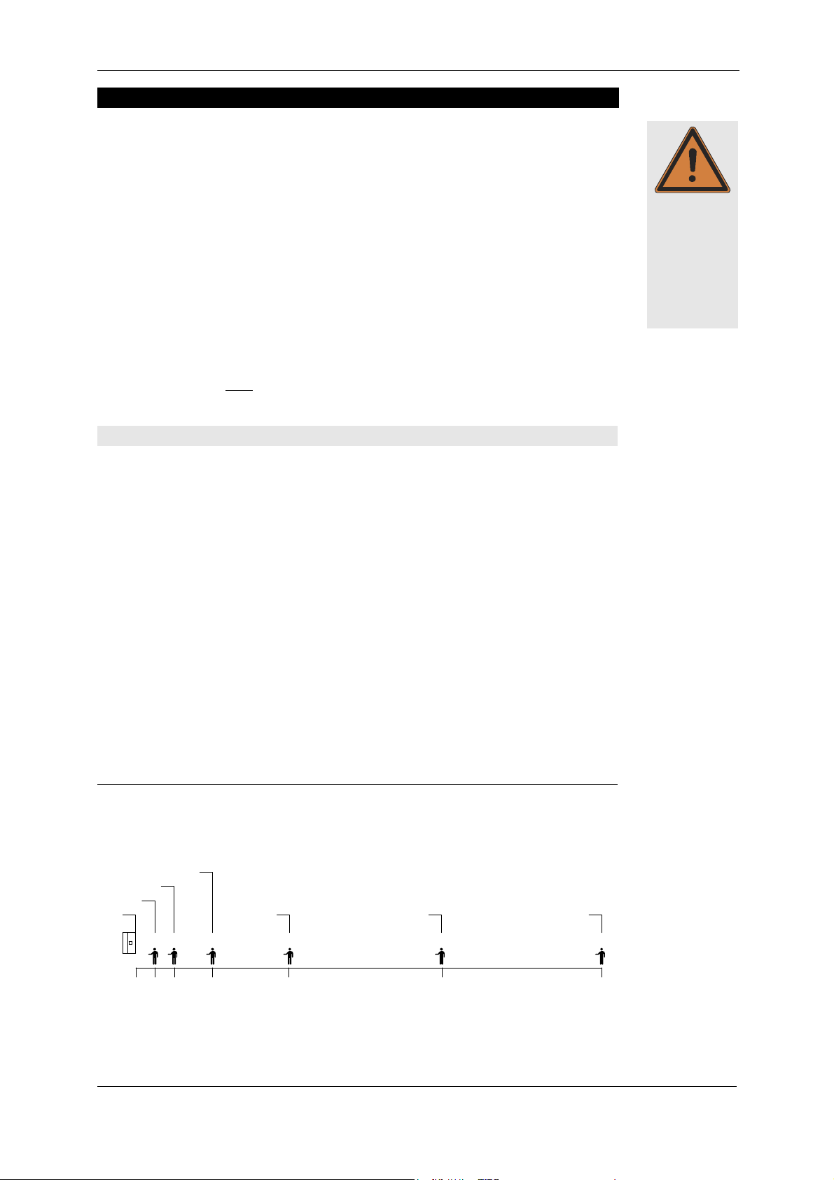
The following graphics will assist in making a rough estimate as to the distance range of
speaker systems. The graphics only take into consideration the sum of the direct sound
and not the influence of the room. Because of this there can, in some cases, be noticeable deviation.
Distance range of SPL (direct sound level):
-12 dB
0 dB
-6 dB
-24 dB -30 dB
2m 4m 8m 16m 32m 50m
-34 dB
KLING & FREITAG GMBH ©2003 - 2014 Version 5.1, 09.09.2014 Page 20 of 44
Page 21

User’s Manual LINE 212-6 - SP / LINE 212-9 - SP
E
Q LOW CUT
Quality (Q)
Bandwidth (oct.)
Level
9.2 Arrayed Speaker Systems (Cluster)
If the loudspeakers are operated through an optional K&F System Controller, we recommend turning on the 'Top Low Cut' filter for clustered operation. Thus the frequency response for this application can be optimised (see user’s manual of the controller).
If the Line 212 Systems are operated in a cluster without a K&F System Controller
(speakers are set up directly next to one another), then lower the 'EQ LOW CUT' frequency as described below!
Frequency
120Hz
0.55
2.35
-2.95dB
1. If several Line 212-6 with a horn coverage pattern of 65°h x 50°v are arranged on
one side (cluster / array), it is recommended for the Line 212-6 to have a horizontal
array angle of 38.5° to one another (see fig. 2).
2. In a cluster comprised of a combination of the Line 212-6 with Line 212-9, we
recommend an array angle of 45° (see fig. 3).
3. With a rotated horn (Line 212-6 standing: 50°h x 65°v / Line 212-9 standing: 50°h
x 90°v), an array angle of 30° is recommended for both versions (see fig. 1).
Because increased interference effects occur when several 90° systems are arranged
next to one another, the clustering of several Line 212- 9 is only conditionally recommendable.
Fig.
Fig. 1111
Fig. Fig.
Fig.
Fig. 2222
Fig.Fig.
Fig.
Fig. 3333
Fig. Fig.
15,0°
8,5°
30,0°
Line 212
Line 212---- 6666
Line 212Line 212
(horn rotated)
horn 50° h x 65° v
Line 212
Line 212----9999
Line 212Line 212
(horn rotated)
horn 50° h x 65° v
Line 212
Line 212----6666
Line 212Line 212
(horn not rotated)
horn 65° h x 50° v
38,5°
Combination
(horns not rotated):
Line 212
Line 212----6666
Line 212Line 212
Horn 65°h x 50°v
with
Line 212
Line 212----9999
Line 212Line 212
45,0°
horn 90°h x 50°v
KLING & FREITAG GMBH ©2003 - 2014 Version 5.0, 09.09.2014 Page 21 of 44
Page 22

User’s Manual LINE 212-6 - SP / LINE 212-9 - SP
9.3 LINE 212 Systems on Top of SW 215E
In addition to the stacking foot grooves for stacks of
idenctical enclosures, the subwoofer SW 215E also has
stacking foot grooves for the Line 212 System.
One Line 212 System can be quickly and safely positioned on top of a vertically placed SW 215E.
Two Line 212 Systems can be precisely arrayed on top of
a horizontally placed SW 215E.
Line 212
Line 212----6666
Line 212Line 212
with
with
withwith
Line 212
Line 212----6666
Line 212Line 212
Line 212
Line 212----6666
Line 212Line 212
with
with
withwith
Line 212
Line 212----9999
Line 212Line 212
Horn
Horn not
not rotated on
Horn Horn
notnot
standing Line 212 syste
standing Line 212 systemmmm
standing Line 212 systestanding Line 212 syste
8,5°
38,5°
15,0°
45°
rotated on
rotated onrotated on
Horn rotated
Horn rotated
Horn rotatedHorn rotated
standing Line 212 system
standing Line 212 system
standing Line 212 systemstanding Line 212 system
30°
Other combinations of Line 212 Systems are not recommended as they can cause unwanted interferences.
KLING & FREITAG GMBH ©2003 - 2014 Version 5.1, 09.09.2014 Page 22 of 44
Page 23

User’s Manual LINE 212-6 - SP / LINE 212-9 - SP
10. Wiring
Before connecting your SP system, be sure to switch off all connected appliances and
turn down all level controls.
− We recommend the use of high-quality cables provided by KLING & FREITAG.
− For connections to the line signal inputs, please use 2-pin shielded microphone cable
with high-quality connectors.
− Avoid ground loops (see chapter 10.1 )
− Make sure that the pin assignment of the line level connectors is correct. (2 +/ 3 - / 1 ┴).
10.1 Avoiding Ground Loops
10.1.1 What is a Ground Loop?
Every component of a P.A. or Hi-Fi System has its own internal 0V reference (ground). This
point is often connected to the protective earth connector (PE / Ground). If two or more
units are connected to one another with a line level audio cable, there may be a ground
connection through the ground of the power supply cable (yellow-green) as well as
through the shielding of the audio cable. The voltage difference between these two
ground points causes audible interference to come from the speaker.
Warning
10.1.2 Avoiding Ground Loops
If there is a loud humming or buzzing after the ‘SP’ System has been connected, then
set the ‘Ground Lift’ switches on the rear of the ‘SP’ speakers to the ‘Lift’ position (chapter: 3 / section 2)
If the noise is still audible, check if
1. the noise is caused by a ground loop before the speakers (e.g. mixing console,
effects or equalizers).
2. the system or parts of the system are connected to an ‘unclean’ power supply -
meaning one which is also running large motors or lighting systems. An ‘unclean’ supply voltage, electrostatic and electromagnetic fields can cause interference
Please observe the following basic rules:
− Never !!! try to avoid a ground loop by disconnecting or taping the ground
contact at the connector! Extremely dangerous!
− If possible, only use high-quality audio appliances with balanced signal outputs and
power cables with PE connectors.
− Use high-quality cables with good shielding.
− The point of ground for all connected components should merge at one central
point. The power connections should lead out in a radial manner from one point
and not be linked from one unit to the next.
− When installing appliances that create strong electrostatic or electromagnetic fields
(large transformers, switch-mode power supplies), maintain some distance from
other audio appliances. In extreme cases, the only solution is to create a completely
independent ‘audio ground’; in other cases, it is sufficient to connect a filter in front
of the audio equipment.
KLING & FREITAG GMBH ©2003 - 2014 Version 5.0, 09.09.2014 Page 23 of 44
Page 24

User’s Manual LINE 212-6 - SP / LINE 212-9 - SP
1.
10.2 Connecting the Power Connectors to the Connecting Terminal
2.
1.
2.
3.
Only use the supplied power cable and connect it to a mains outlet with a 16 A fuse.
See instructions in chapter 4‚ ‘Power Cord’ on page 13.
Warning
KLING & FREITAG GMBH ©2003 - 2014 Version 5.1, 09.09.2014 Page 24 of 44
Page 25

User’s Manual LINE 212-6 - SP / LINE 212-9 - SP
EQ HIGH B
O
OST EQ LOW CUT
Bandw
idth (oct.)
Level
11. Configurations and Connecting Diagrams
11.1 Operating the Systems without K&F System Controller
The full-range system can be used alone or in conjunction with an SP subwoofer. The
subwoofer has an integrated filter for use in this mode, which limits the bandwidth.
The full-range system is protected against low frequency (subsonic) signals by a highpass filter and when used with bass speakers it is phase aligned with the subwoofers by
means of alignment filters.
11.1.1 Full-Range Mode
This mode of operation is ideal for speech and music applications without the need for
a high bass content. Should more bass be needed, the bass level can be increased between 50 and 80 Hz at the mixing console.
The switch ‘FILTERS’ on
The switch ‘FILTERS’ on
The switch ‘FILTERS’ on The switch ‘FILTERS’ on
the SP speaker must be
the SP speaker must be
the SP speaker must be the SP speaker must be
at ‘ON’ in this mode.
at ‘ON’ in this mode.
at ‘ON’ in this mode.at ‘ON’ in this mode.
If you need a high-boost for covering larger distances (compensation of high frequency
attenuation), then increase the ‘EQ HIGH BOOST’ frequency as described below!
If the mid-high systems are operated in a cluster (speakers are set up directly next to one
another), then lower the ‘EQ LOW CUT’ frequency as described below!
LINE
AC-MAINS
Frequency
Quality (Q)
INPUTChannel 2 Channel 1
14000Hz
2.6
0.55
+4.4dB
120Hz
0.55
2.35
-2.95dB
LINE
AC-MAINS
AC ~ 16 A max.AC ~ 16 A max.
KLING & FREITAG GMBH ©2003 - 2014 Version 5.0, 09.09.2014 Page 25 of 44
Page 26

User’s Manual LINE 212-6 - SP / LINE 212-9 - SP
EQ HIGH BOOST
EQ LOW CUT
Quality (Q)
Bandwidth (oct.)
Level
11.1.2 Full Range Mode with Subwoofer
You can link the input signal (for example from the mixer) from one loudspeaker to
another. It makes no difference whether the input signal reaches the bass speaker first
and is then transmitted to the mid-high speaker or the other way around.
The switch ‘FILTERS’ on
The switch ‘FILTERS’ on
The switch ‘FILTERS’ on The switch ‘FILTERS’ on
the SP speaker must be at
the SP speaker must be at
the SP speaker must be at the SP speaker must be at
‘ON’ in this mode.
‘ON’ in this mode.
‘ON’ in this mode.‘ON’ in this mode.
If you need a high-boost for covering larger distances (compensation of high frequency
attenuation), then increase the ‘EQ HIGH BOOST’ frequency as in the following table!
If the mid-high systems are operated in a cluster (speakers are set up directly next to one
another), then lower the ‘EQ LOW CUT’ frequency as described below!
LINE
AC-MAINS
Frequency
To next
'SP'-Top
or Sub
14000Hz
2.6
0.55
+4.4dB
120Hz
0.55
2.35
-2.95dB
To next
'SP'-Top
or Sub
LINE
AC-MAINS
LINE
AC-MAINS
AC ~ 16 A max.
Channel 1
INPUT
Channel 2
LINE
AC-MAINS
AC ~ 16 A max.
KLING & FREITAG GMBH ©2003 - 2014 Version 5.1, 09.09.2014 Page 26 of 44
Page 27
User’s Manual LINE 212-6 - SP / LINE 212-9 - SP
Ω
Ω
=
75
R
Ω
66
n
<
⇒
11.2 Operating the Systems with K&F System Controller
For optimal performance with an extended functional range we recommend using a
K&F system controller. Instructions for use, connecting diagrams and detailed descriptions of the latest controller models ‘CD 24’ and ‘CD 44’ you can find in the corresponding user’s manuals.
11.3 Maximum Configuration
It is possible to use a large number of SP speakers in parallel simultaneously, however,
this number is limited according to the permitted minimum load impedance of the signal source (e.g. mixer, equalizer, etc.).
The total input impedance of all SP speakers must be larger than the permitted minimum load impedance of the signal source. If no manufacturer’s recommendations can
be found, take the output impedance of the signal source. In this case, we recommend
a total input impedance at least 10 times higher than the stated output impedance of
Important
the signal source.
(The output impedance of your signal source can normally be found under ‘Technical
Specifications’ in the manufacturer’s instruction manual).
Definition:
OUT
IN
MAX
=
=
source signal of impedance output R
50.000Ω 50kΩ speaker - SP impedance input R
===
speakers SP of number drecommende maximum n
The maximum number of SP speakers can be calculated with this formula:
50
n
MAX.
R
IN
<
10
×
R
k
=
R
OUTOUT
10
×
Example:
OUT
n
MAX.
R
IN
<
OUT
10
×
000.50
Ω
1075
xR
=
MAX.
KLING & FREITAG GMBH ©2003 - 2014 Version 5.0, 09.09.2014 Page 27 of 44
Page 28

User’s Manual LINE 212-6 - SP / LINE 212-9 - SP
12. Operating the Speakers
− Switch off all equipment and make sure that the SP speakers are not connected to a
power source.
− Connect your SP systems in accordance with the preceding connection diagrams.
Use only mains cables, which comply with your national safety regulations.
− Upon completing the wiring, ensure that the connected speakers are working in phase. To
do so, use i.e. a phase checker. A phase error can also be recognized when the connected
channels are used simultaneously. During simultaneous use the bass frequencies become
notably quieter or the mid-frequencies such as voices cannot be located.
Warning
− Switch on first the peripheral units (mixer, effects, etc.), then, if used, the K&F System
Controller and connect lastly the SP loudspeakers. Always use the before mentioned
switching order. Otherwise switching noises may damage the system.
− If there is interference, turn off all appliances in the reverse order and check all cable
connections. Next, turn up all other peripheral units, and check these for interference.
− Your system should now be ready for operation.
− You can now turn up the level on the mixer.
− If you are using additional bass systems, you can now balance the respective volume
levels of the top speakers and bass systems. A fine adjustment of the system without
K&F System Controller can be obtained using the gain control on the SP loudspeakers
(not on the mixing console!).
− When switching off the system first disconnect the ‘SP’ loudspeakers. Then you can switch
off the remaining units.
13. Touching Up Damage to Paint / Changing the Front Foam
Although the PU structured paint used by KLING & FREITAG is extremely resistant, we
recommend using protective covers or cases to help avoid damaging the paint during
i.e. continuous mobile use. If paint damage occurs despite these precautions, it can be
touched up by using commercial acrylic paint in the appropriate RAL colour of the
speaker. To replace the filter foam, send the front grille incl. foam to KLING & FREITAG
GmbH. Upon payment for expenses, the grille with the new covering will be returned.
Important
KLING & FREITAG GMBH ©2003 - 2014 Version 5.1, 09.09.2014 Page 28 of 44
Page 29

User’s Manual LINE 212-6 - SP / LINE 212-9 - SP
SCHEMATIC LINE 212 - 'SP'
14. Block Diagram LINE 212 - SP
12 V DC
±
LINE 212
CIRCUIT
POTECTION
POWER
SUPPLY
FILTER AMP
ERROR
SIGNAL
AMP
DIGITAL
THRESHOLD PEAKTHRESHOLD RMS
SIGNAL
RMS
+ PEAK
LIMITER
ERROR
POWER 'ON'
ERROR
CONTROLLER
FUSE
AMPLIFIER UNIT 2
HF-
CIRCUIT
POTECTION
CONTROL
AMP
DIGITAL
LED
BI-COLOUR
CORRECTION
FILTERBOARD 'LINE 212'
PHASE-CORRECTION
'
POWER SUPPLY
FUSE
F
F
O
'
/
'
N
O
'
S
R
E
T
L
I
F
HI-PASS
HI-PASS
AMPLIFIER UNIT 1
6 dB
±
GAIN
PASSIVE CROSSOVER
LINE 212 - SP
HF
LF 1
LF 2
T
F
I
L
L
L
N
N
D
N
G
2
3
2
3
1
INPUT UNIT
1
KLING & FREITAG GMBH ©2003 - 2014 Version 5.0, 09.09.2014 Page 29 of 44
Page 30

User’s Manual LINE 212-6 - SP / LINE 212-9 - SP
15. Technical Specifications
15.1 LINE 212-6 - SP
Loudspeaker
Loudspeaker
LoudspeakerLoudspeaker
Design 2+1-way full-range system with integrated driver and
power amplifier technology,
completely horn loaded, bass reflex tuning
Frequency range -10 dB 51 Hz - 20 kHz ('FILTERS ON'), 65 Hz - 20 kHz ('FILTERS OFF')
49 Hz - 20 kHz ('FILTERS OFF' with K&F System Controller)
Frequency range ± 3 dB 66 Hz - 18 kHz ('FILTERS ON'), 130 Hz - 18 kHz ('FILTERS OFF')
60 Hz - 18 kHz ('FILTERS OFF' with K&F System Controller)
Nominal coverage angle 65° x 50° / rotatable horn
Directivity index (DI) 12 (+1.5/-3) 600 Hz - 16 kHz
Max. SPL 135 dB (SPL peak/1 m)
Components 1 x 12‘‘ woofer and 1 x 12‘‘ low-mid chassis with horns,
1.5‘‘ high freq. driver with 75 mm titanium dome on
rotatable CD horn
Crossover Active (1) and passive (2) in FLC technology, delay time
correction and phase optimisation, self-resetting
protection circuit for 1.5‘‘ driver
Supply voltage AC 195-250 V, 50 / 60 Hz (230 V version)
alternative AC 95-125 V, 50 / 60 Hz (115 V version)
Power consumption (nominal) @ 230 V: 1.25 A @ 115 V: 2.5 A
Max. Power consump. (Irms / <500 ms) @ 230 V: 8 A @ 115 V: 16 A
Idle current @ 230 V: 360mA @ 115 V: 720 mA
Power connectors Neutrik PowerCon, lockable, 1 input and 1 output
Input module
Input module
Input moduleInput module
Signal connectors Pin 1 = ground / pin 2 = + signal / pin 3 = - signal
LINE IN: XLR 3 pin female
LINE OUT: XLR 3 pin male, parallel with LINE IN
Input sensitivity +6 dB / 1.55 Vrms for rated output
Input impedance 50 kW (balanced / unbalanced)
Common mode rejection Min.: 74 dB, typical: 90 dB
Controls Level control ± 6 dB, bypass switch for the
active filters (for operations with K&F System Controller),
ground lift switch
Display Bi-coloured LED: green = Power On,
red = Limit / Protect
Driver circuit Peak limiter, RMS limiter
High-pass 45 Hz (-3 dB), 24 dB / octave (‘FILTERS ON’),
Phase correction, frequency equalisation (EQ)
Amplifier module (2 x)
Amplifier module (2 x)
Amplifier module (2 x)Amplifier module (2 x)
Type Class D
Power
Power bandwidth 10 Hz to 30 kHz
Damping factor > 500 (100 Hz), > 100 (10 kHz)
S / N ratio > 105 dB (A)
Cooling Air convection (without fan)
Protection circuits Short circuit, over-temperature, clipping, overload
Enclos
Enclosure
ure
EnclosEnclos
ureure
Trapezoidal, frame-reinforced 15 mm birch plywood with
with highly resistable grey or black structured paint,
2 butterfly handles, ball proof front grille with
exchangeable black acoustic foam
Rigging 4 flying points ‘allsafe JUNGFALK’
1 rear mounted flying track ‘allsafe JUNGFALK’
Dimensions 429 x 1025 x 510 mm (W x H x D)
Weight 57.5 kg
Options special finish in RAL colours
1000 W @ 8 Ω ( EIAJ / 1 kHz, 1% THD)
KLING & FREITAG GMBH ©2003 - 2014 Version 5.1, 09.09.2014 Page 30 of 44
Page 31

User’s Manual LINE 212-6 - SP / LINE 212-9 - SP
Technical changes without prior notice reserved
KLING & FREITAG GMBH ©2003 - 2014 Version 5.0, 09.09.2014 Page 31 of 44
Page 32

User’s Manual LINE 212-6 - SP / LINE 212-9 - SP
15.2 LINE 212-9 - SP
Loudspeaker
Loudspeaker
LoudspeakerLoudspeaker
Design 2+1-way full-range system with integrated driver and
power amplifier technology,
completely horn loaded, bass reflex tuning
Frequency range -10 dB 51 Hz - 20 kHz ('FILTERS ON'), 65 Hz - 20 kHz ('FILTERS OFF')
49 Hz - 20 kHz ('FILTERS OFF' with K&F System Controller)
Frequency range ± 3 dB 66 Hz - 18 kHz ('FILTERS ON'), 130 Hz - 18 kHz ('FILTERS OFF')
60 Hz - 18 kHz ('FILTERS OFF' with K&F System Controller)
Nominal coverage angle 90° x 50° / rotatable horn
Directivity index (DI) 10 (±1.5) 600 Hz - 12 kHz
Max. SPL 135 dB (SPL peak/1 m)
Components 1 x 12‘‘ woofer and 1 x 12‘‘ low-mid chassis with horns,
1.5‘‘ high freq. driver with 75 mm titanium dome on
rotatable CD horn
Crossover Active (1) and passive (2) in FLC technology, delay time
correction and phase optimisation, self-resetting
protection circuit for 1.5‘‘ driver
Supply voltage AC 195-250 V, 50 / 60 Hz (230 V version)
alternative AC 95-125 V, 50 / 60 Hz (115 V version)
Power consumption (nominal) @ 230 V: 1.25 A @ 115 V: 2.5 A
Max. Power consump. (Irms / <500 ms) @ 230 V: 8 A @ 115 V: 16 A
Idle current @ 230 V: 360mA @ 115 V: 720 mA
Power connectors Neutrik PowerCon, lockable, 1 input and 1 output
Input module
Input module
Input moduleInput module
Signal connectors Pin 1 = ground / pin 2 = + signal / pin 3 = - signal
LINE IN: XLR 3 pin female
LINE OUT: XLR 3 pin male, parallel with LINE IN
Input sensitivity +6 dB / 1.55 Vrms for rated output
Input impedance 50 kW (balanced / unbalanced)
Common mode rejection Min.: 74 dB, typical: 90 dB
Controls Level control ± 6 dB, bypass switch for the
active filters (for operations with K&F System Controller),
ground lift switch
Display Bi-coloured LED: green = Power On,
red = Limit / Protect
Driver circuit Peak limiter, RMS limiter
High-pass 45 Hz (-3 dB), 24 dB / octave (‘FILTERS ON’),
Phase correction, frequency equalisation (EQ)
Amplifier module (2 x)
Amplifier module (2 x)
Amplifier module (2 x)Amplifier module (2 x)
Type Class D
Power
Power bandwidth 10 Hz to 30 kHz
Damping factor > 500 (100 Hz), > 100 (10 kHz)
S / N ratio > 105 dB (A)
Cooling Air convection (without fan)
Protection circuits Short circuit, over-temperature, clipping, overload
Enclos
Enclosure
ure
EnclosEnclos
ureure
Trapezoidal, frame-reinforced 15 mm birch plywood with
with highly resistable grey or black structured paint,
2 butterfly handles, ball proof front grille with
exchangeable black acoustic foam
Rigging 4 flying points ‘allsafe JUNGFALK’
1 rear mounted flying track ‘allsafe JUNGFALK’
Dimensions 429 x 1025 x 510 mm (W x H x D)
Weight 57.5 kg
Options special finish in RAL colours
Technical changes without prior notice reserved
1000 W @ 8 Ω ( EIAJ / 1 kHz, 1% THD)
KLING & FREITAG GMBH ©2003 - 2014 Version 5.1, 09.09.2014 Page 32 of 44
Page 33

User’s Manual LINE 212-6 - SP / LINE 212-9 - SP
-6dB Beamwidth (degr
ees)
20000
360
20
100
Dir
ectivityI ndex (DI), dB
SPL
(dB)
Filters 'OFF'
16. Measuring Charts
16.1 LINE 212-6 - SP
Frequency response ‘on axis’
115
105
95
85
75
20 100 1000 10000 20000
Frequency (Hz)
Beamwidth
Filters 'ON'
300
240
180
120
60
0
20
100 1000 10000
Frequency (Hz)
Horizontal
Vertical
Q-Index
10
0
20 100 1000 10000 20000
Frequency (Hz)
10
Directivity Factor (Q)
1
KLING & FREITAG GMBH ©2003 - 2014 Version 5.0, 09.09.2014 Page 33 of 44
Page 34
User’s Manual LINE 212-6 - SP / LINE 212-9 - SP
1
180
°
180
°
Attenuation in dB
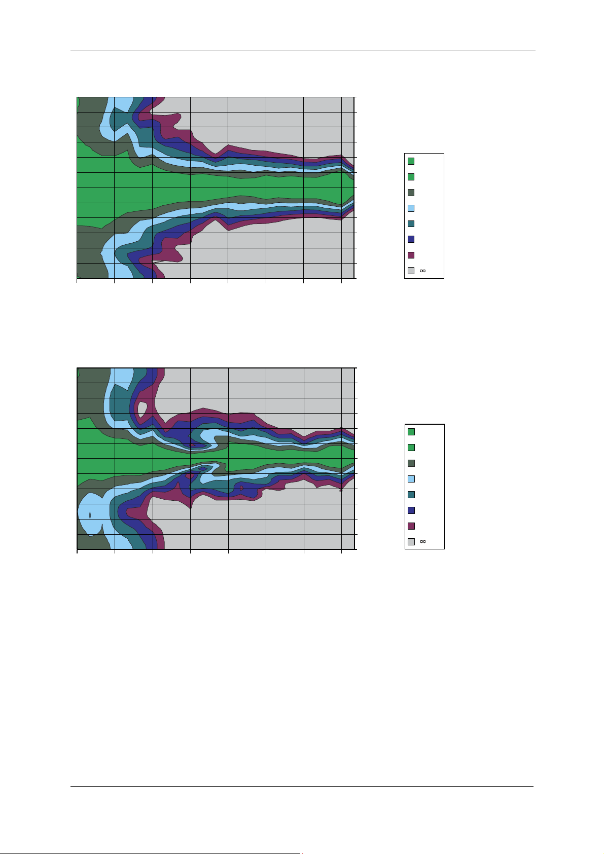
Horizontal coverage pattern
150°
120°
90°
60°
30°
0°
-30°
-60°
-90°
-120°
-150°
-180°
25 250 500 1k 2k 4k 8k 16K
f [Hz]
0-3
-3-0
-6--3
-9--6
-12--9
-15--12
-18--15
- --18
Vertical coverage pattern
125 250 500 1k 2k 4k 8k 16K
f [Hz]
150°
120°
90°
Attenuation in dB
60°
30°
0°
-30°
-60°
-90°
-120°
-150°
-180°
0-3
-3-0
-6--3
-9--6
-12--9
-15--12
-18--15
- --18
KLING & FREITAG GMBH ©2003 - 2014 Version 5.1, 09.09.2014 Page 34 of 44
Page 35

User’s Manual LINE 212-6 - SP / LINE 212-9 - SP
-6dB Beamwidth (degr
ees)
20000
360
20
100
Dir
ectivityI ndex (DI), dB
PL
SPL
(dB)
Filters 'OFF'
16.2 LINE 212-9 - SP
Frequency response 'on axis'
115
105
95
(dB
S
85
75
20 100 1000 10000 20000
Frequency (Hz)
Beamwidth
Filters 'ON'
300
240
180
120
60
0
20
Q-Index
10
Horizontal
Vertical
100 1000 10000
Frequency (Hz)
10
Directivity Factor (Q)
0
20 100 1000 10000 20000
Frequency (Hz)
1
KLING & FREITAG GMBH ©2003 - 2014 Version 5.0, 09.09.2014 Page 35 of 44
Page 36

User’s Manual LINE 212-6 - SP / LINE 212-9 - SP
1
180
°
1
180
°
Horizontal coverage pattern
150°
120°
90°
Attenuation in dB
60°
30°
0°
-30°
-60°
-90°
-120°
-150°
-180°
25 250 500 1k 2k 4k 8k 16K
f [Hz]
0-3
-3-0
-6--3
-9--6
-12--9
-15--12
-18--15
-21--18
Vertical coverage pattern
25 250 500 1k 2k 4k 8k 16K
f [Hz]
150°
120°
90°
60°
30°
0°
-30°
-60°
-90°
-120°
-150°
-180°
Attenuation in dB
0-3
-3-0
-6--3
-9--6
-12--9
-15--12
-18--15
-21--18
KLING & FREITAG GMBH ©2003 - 2014 Version 5.1, 09.09.2014 Page 36 of 44
Page 37

User’s Manual LINE 212-6 - SP / LINE 212-9 - SP
ANCRA Jungfalk
[10.467"]
17. Dimensions
Flugpunkte
ANCRA Jungfalk
120030-31
Kunststofffüße
Flugschiene
71202
1015 mm
[39.961"]
10 mm
[0.033"]
429 mm
[16.890"]
Stapelmulden
222 mm
[8.740"]
15°
81.6 mm
[3.211"]
265.9 mm
510 mm
[20.079"]
507.5 mm
214.6 mm
[8.450"]
[19.980"]
KLING & FREITAG GMBH ©2003 - 2014 Version 5.0, 09.09.2014 Page 37 of 44
Page 38

User’s Manual LINE 212-6 - SP / LINE 212-9 - SP
18. Accessories for the LINE 212 System
Click & Fly
Quick Release Pin
®
Connector 30° Connector 38.5° Connector 45°
Application examples Click & Fly® LINE 212
Single Stud Fitting Double Stud Fitting Rigging chain, adjustable (left / right)
Transport cover with castors
KLING & FREITAG GMBH ©2003 - 2014 Version 5.1, 09.09.2014 Page 38 of 44
Page 39

User’s Manual LINE 212-6 - SP / LINE 212-9 - SP
19. Regulations for Disposal
19.1 Germany
It is not allowed to dispose of used electrical equipment as domestic waste.
But please do not dispose of them at official collecting points for recycling either!
All Kling & Freitag products are plain business-to-business (B2B) products.
Disposal of Kling & Freitag products labelled with a waste bin sign have thus to be disposed of by Kling & Freitag alone. Please call Kling & Freitag at the number stated below
if you have a Kling & Freitag product to be disposed. We will offer you a straightforward
and professional disposal not affecting costs.
If there is no dustbin sign on one of your Kling & Freitag products, because they have
been sold before March 2006 then by law the owner is in charge of the disposal. For
these we will be happy to assist and offer you proper ways of disposal.
Telephone number to call about the disposal of used Kling & Freitag products:
+49 (511)-96 99 7-0
Explanation: With the ElektroG (law relating to electrical and electronic equipment and appliances) we have complied with the EUdirective on waste electrical and electronic equipment (WEEE,
2002/96/EC)
The Kling & Freitag GmbH has thus labelled all products mentioned
in the WEEE from 03/24/2006 onwards with a sign with a crossed
out waste bin and a white bar below. This sign indicates that the
disposal into the domestic waste is prohibited and that the product
has been put into circulation at the 03/24/2006 earliest.
The Kling & Freitag GmbH has been legally registered as a manufacturer with the registration office EAR. Our WEEE Registration-Nr. is: DE64110372
For the German Registration office EAR we have accredited that our products are sole
B2B products.
19.2 EU, Norway, Iceland, and Liechtenstein
It is not allowed to dispose of used electrical equipment as
domestic waste.
The Kling & Freitag GmbH has thus labelled all products coming
from EU-Member countries as well as Norway, Island and Liechtenstein (except Germany) mentioned in the WEEE from 08/13/2005
onwards with a sign with a crossed out waste bin and a white bar
below. This sign indicates that the disposal into the domestic waste
is prohibited and that the product has been put into circulation at
the 08/13/2005 earliest.
Unfortunately the European directive WEEE has been complied with implementing different national provisions of law throughout all member countries, which makes it impossible for us to offer consistent solutions for the disposal throughout Europe.
Responsible for complying with these provisions of law is the local distributor (importer)
of each country.
For proper disposition of used products in accordance with these local provisions in
the mentioned countries of the European Union (except Germany) please ask your
local dealer or the local authorities.
19.3 Other Countries
For proper disposition of used products in accordance with local provisions in other
countries please ask your local dealer or the local authorities.
KLING & FREITAG GMBH ©2003 - 2014 Version 5.0, 09.09.2014 Page 39 of 44
Page 40

User’s Manual LINE 212-6 - SP / LINE 212-9 - SP
20. Declaration of Conformity and International Certificates
20.1 Declaration of Conformity
EG-Konformitätserklärung
EMV Richtlinie 89 / 336 / EWG
Niederspannungsrichtlinie: 73 / 23 / EWG
Wir: KLING & FREITAG GMBH
Junkersstraße 14
30179 Hannover
Deutschland
erklären eigenverantwortlich, dass folgende Produkte:
Art: Lautsprecher mit integrierten Endverstärkern
Modelle: CA 1001 - SP,
CA 1201 - SP,
CA 1215-6 - SP, CA 1215-9 - SP,
CA 1515-6 - SP, CA 1515-9 - SP,
LINE 212-6 - SP, LINE 212-9 - SP,
SW 112 - SP, SWi 112 - SP,
SW 115D - SP, SWi 115D - SP,
SW 115E - SP, SWi 115E - SP,
SW
118E - SP, SWi 118E - SP,
SW 215E - SP
den Anforderungen folgender Normen und Dokumente entsprechen:
EN 60065:1998;
E9 05 05 50454 004
Hannover, 23.03.2006
Ort, Datum Geschäftsführer
Akkreditiertes Prüflaboratorium: MIKES BABT PRODUCT SERVICE GmbH, Ohmstraße 2-4
D-94342 Strasskirchen
Jürgen Freitag
KLING & FREITAG GMBH ©2003 - 2014 Version 5.1, 09.09.2014 Page 40 of 44
Page 41

User’s Manual LINE 212-6 - SP / LINE 212-9 - SP
20.2 EMV Certificate Directive 89 / 336 / EWG
KLING & FREITAG GMBH ©2003 - 2014 Version 5.0, 09.09.2014 Page 41 of 44
Page 42

User’s Manual LINE 212-6 - SP / LINE 212-9 - SP
Das verknüpfte Bild kann nicht angezeigt werden. Mög licherweise wurde die Datei verschoben, umbenan nt oder gelöscht. Stellen Sie sicher, dass die Verknüpfu ng auf die korrek te Datei und den korrek ten Speicherort zeigt.
KLING & FREITAG GMBH ©2003 - 2014 Version 5.1, 09.09.2014 Page 42 of 44
Page 43

User’s Manual LINE 212-6 - SP / LINE 212-9 - SP
20.3 TÜV Certificatefor USA und Canada (UL 6500)
KLING & FREITAG GMBH ©2003 - 2014 Version 5.0, 09.09.2014 Page 43 of 44
Page 44

User’s Manual LINE 212-6 - SP / LINE 212-9 - SP
KLING & FREITAG GMBH ©2003 - 2014 Version 5.1, 09.09.2014 Page 44 of 44
 Loading...