

Page 1
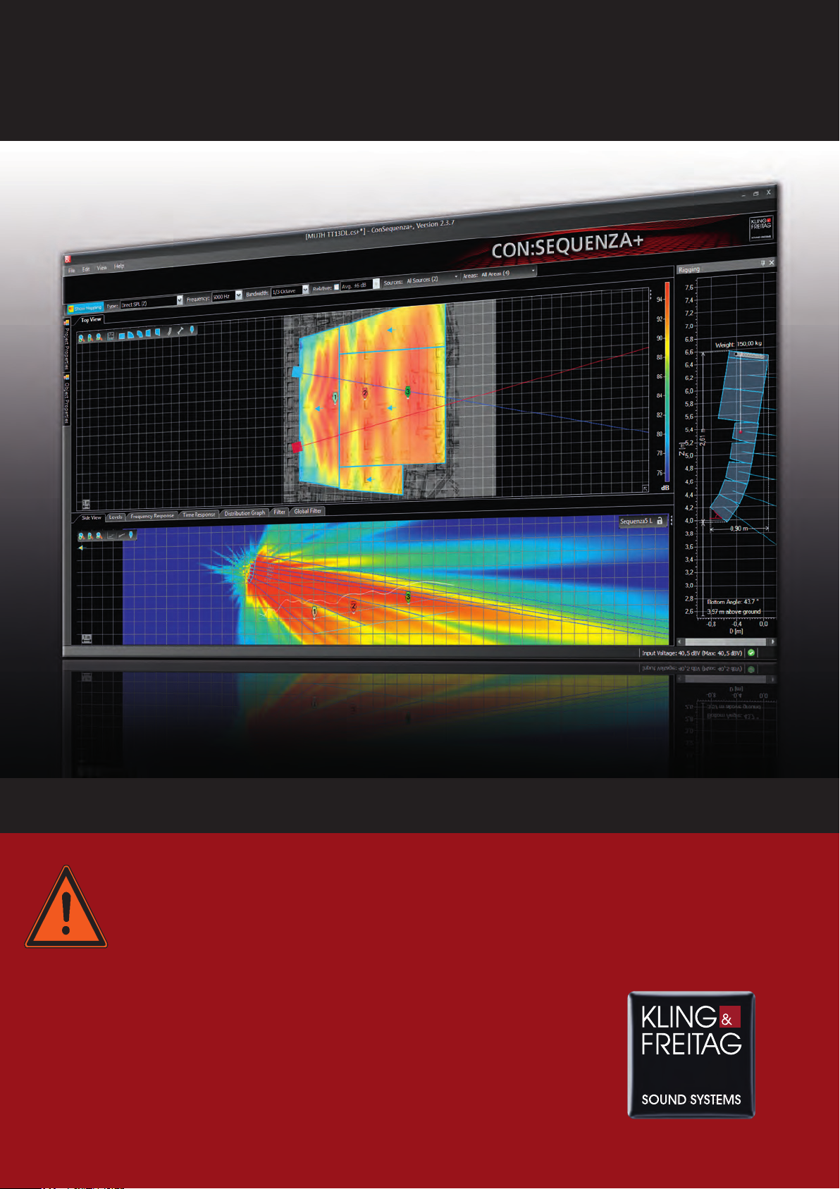
K&F CON:SEQUENZA+
User's Manual
Important Informationen,
Please Read Before Use!
KLING & FREITAG GmbH
Junkersstraße 14
D-30179 Hannover
TEL +49 (0) 511 96 99 70
FAX +49 (0) 511 67 37 94
www.kling-freitag.de
Version 1.1.
Released: 30.09.2013
Page 2

User’s Guide K&F CON:SEQUENZA+
Table of Contents
1. Introduction to CON:SEQUENZA+ 4
1.1 Software Overview ...................................................................................................................4
1.2 System Requirements ...............................................................................................................4
1.3 How to Install ..........................................................................................................................5
1.4 User Interface ..........................................................................................................................6
1.5 Program Conventions ..............................................................................................................8
1.6 Shortcut List .......................................................................................................................... 10
2. Venue Definition and Line Arrays 12
2.1 Project Properties ................................................................................................................... 12
2.2 Top View ............................................................................................................................... 13
2.3 Side View .............................................................................................................................. 16
2.4 Adding Audience Zones ......................................................................................................... 17
2.5 Editing Audience Zones .......................................................................................................... 19
2.6 Copying Areas between Zones ............................................................................................... 24
2.7 Saving Projects ....................................................................................................................... 25
2.8 Loading Projects .................................................................................................................... 26
2.9 Importing System Definitions .................................................................................................. 26
2.10 Adding Line Arrays................................................................................................................. 26
2.11 Editing Line Arrays ................................................................................................................. 27
2.12 Auto Splay ............................................................................................................................. 28
2.13 Copying Setups between Similar Line Arrays ........................................................................... 30
2.14 Regular Loudspeakers ............................................................................................................ 31
KLING & FREITAG GmbH Version 1.0 Seite 2 von 53
Page 3

User’s Guide K&F CON:SEQUENZA+
3. Mapping and Calculation Results 32
3.1 Mapping Toolbar ................................................................................................................... 32
3.2 Calculations Background ........................................................................................................ 32
3.3 Mapping Options ................................................................................................................... 33
3.4 Levels .................................................................................................................................... 35
3.5 Distribution Graph ................................................................................................................. 35
3.6 Adding Receivers ................................................................................................................... 36
3.7 Frequency Response ............................................................................................................... 37
3.8 Sound Source Groups ............................................................................................................ 38
3.9 Audience Area Groups ........................................................................................................... 40
3.10 Exporting Pictures .................................................................................................................. 41
3.11 Creating Reports .................................................................................................................... 42
4. Options 43
4.1 View ..................................................................................................................................... 43
4.2 Grid and Snap ....................................................................................................................... 44
4.3 Environment .......................................................................................................................... 44
5. Advanced Features 46
5.1 Setting Layout Pictures ........................................................................................................... 46
5.2 Adding Section Planes ............................................................................................................ 47
5.3 Filter ...................................................................................................................................... 49
5.4 Filter Settings for Line Arrays .................................................................................................. 50
5.5 Time Response ....................................................................................................................... 51
5.6 Moving the Origin.................................................................................................................. 52
5.7 Noise Settings ........................................................................................................................ 52
KLING & FREITAG GmbH Version 1.0 Seite 3 von 53
Page 4
User’s Guide K&F CON:SEQUENZA+
1
1 Introduction to CON:SEQUENZA+
11
1.1 Software Overview
CON:SEQUENZA+ is a three-dimensional acoustic simulation software for the configuration and
modeling of Kling & Freitag line array systems and K&F loudspeakers. The software is free to
download on http://www.kling-freitag.de.
In CON:SEQUENZA+, each line array or loudspeaker is described by a system definition which
contains the mechanical, electronic and acoustic properties of the loudspeaker system. These
system definitions are stored in a GLL file which can be updated.
This software takes a large step forward towards more realistic modeling of complex sound
systems by including the following major features:
• 3D modeling of direct sound, displayed in horizontal and vertical cutting planes.
• Use multiple K&F line array systems and K&F loudspeakers in a single project.
• Virtual equalizer for tuning a line array in the simulation.
• Full frequency range from 20 Hz to 20 kHz.
• Static Analysis based on BGV C1 and DIN 18800.
CON:SEQUENZA+ is intuitive and easy-to-use with its three-dimensional coordinates and many
useful features. It can be considered a tool for both the end user, who needs to set up the sound
system for a show, as well as for the R&D engineer, who is interested in the acoustic qualities of
the array design. CON:SEQUENZA+ is the optimal tool for easy and quick prediction of the sound
system performance in a given venue.
For more information, including the latest news and updates, visit http://kling-freitag.de.
1.2 System Requirements
1.2.1 Minimum software requirements
• Microsoft Windows 2000, XP, Vista or 7.
• Acrobat Reader 5.0 (or later).
• Microsoft .NET Framework v 4.0 , which can be downloaded here:
http://www.microsoft.com/downloads/
1.2.2 Minimum hardware requirements
• 1 GB RAM (2 GB or more recommended, especially for Vista and 7)
• 990 x 600 display resolution (1024 x 768 or higher recommended display resolution)
KLING & FREITAG GmbH Version 1.0 Seite 4 von 53
Page 5
User’s Guide K&F CON:SEQUENZA+
• 1.5 GHz processor speed or higher (multiple cores are supported and recommended)
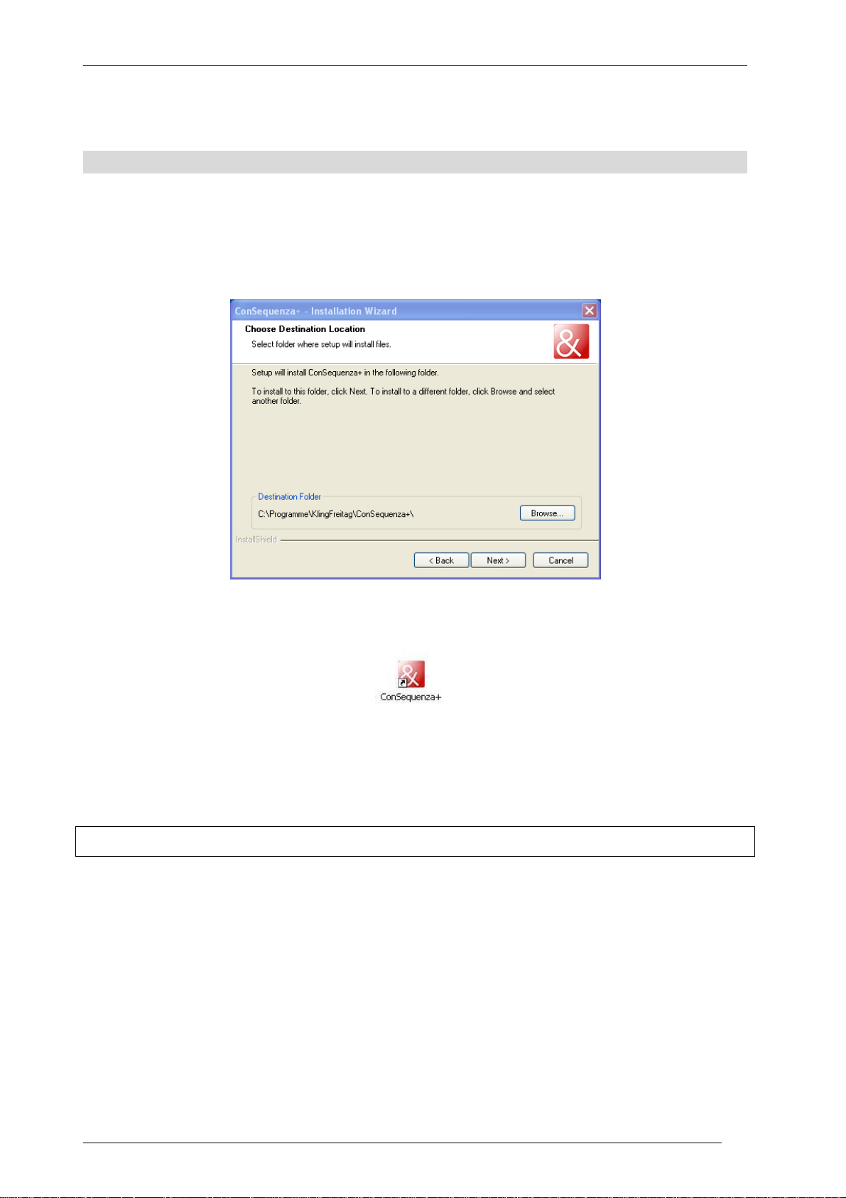
1.3 How to Install
To install CON:SEQUENZA+, unpack the ZIP file and double click on the executable named
“setup”. This will launch the setup utility that will install the program in a few easy steps. Note
that for the installation you will need administrator rights on your computer. By default it will be
installed to this new location:
After the installation has completed successfully you can launch CON:SEQUENZA+ using the
desktop icon or the Windows Start menu.
The software can be found in the CON:SEQUENZA+ folder. If you should experience problems with
CON:SEQUENZA+ at any time later, try starting the software with its default settings. This option is
available as a command from the Windows Start menu.
1.3.1 Initial Setup of the Program
CON:SEQUENZA+ has two language options: English and German. Normally the first time
CON:SEQUENZA+ is run it will detect the language of your operating system and use it
automatically. If you wish to change the default language, press F9 for the Options window and
switch to the Environment page. Then select the desired language from the Language drop-down
list at the very top. (See §4.3)
The installation package of CON:SEQUENZA+ includes the K&F line array series Sequenza and a
number of K&F loudspeakers. But if there are new or updated system definition files, that is, GLL
or DLL files, you may want to add them to your local database in order to make them available in
CON:SEQUENZA+. To do that press Ctrl+I or select Import System Definition File from the Edit
menu. A file dialog will open which allows you to select the GLL file of interest. Note that the
KLING & FREITAG GmbH Version 1.0 Seite 5 von 53
Page 6

User’s Guide K&F CON:SEQUENZA+
program will make a full copy of this file so you don’t have to worry about removing it from the
original location after the import. (See §2.9)
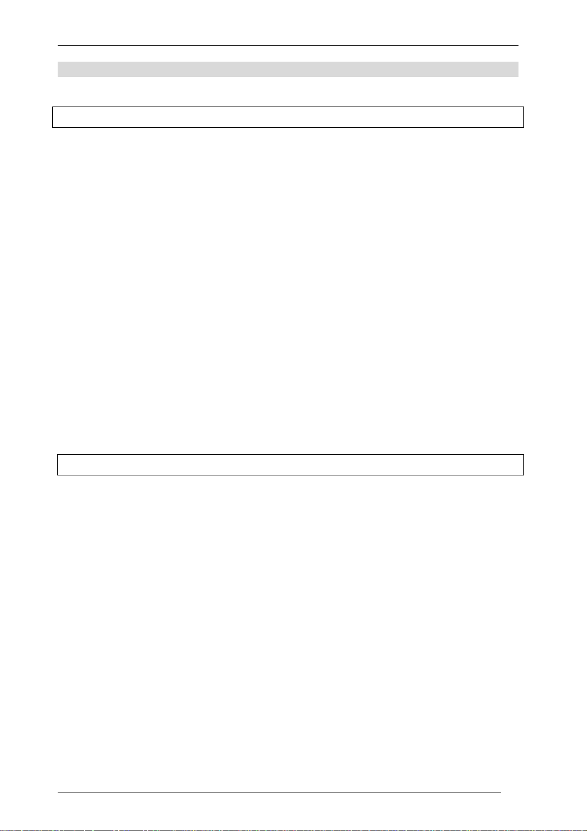
1.4 User Interface
The software GUI is subdivided into 4 screen areas:
• Left: Project Properties (§2.1) and Object Properties, used for editing Line Arrays (§2.11)
and Loudspeakers (§2.14), Audience Zones (§2.5), Receivers (§3.6) and Section Planes
(§5.2).
• Top: Top View (§2.2), horizontal coverage. This allows selecting, entering and modifying
Audience Zones, Receivers, Line Arrays, Loudspeakers and Section Planes in the X-Ydomain.
• Bottom: Side View (§2.3), vertical coverage. This allows entering and modifying Audience
Areas for the selected Zone or changing the aiming and position of the selected Line Array
system. Additional tabs can be used to select Frequency Response (§3.7), Levels (§3.4) and
Distribution (§3.5). In the Extended mode, Time Response (§5.5), source Filter and Global
Filter (§5.3) are also available. For information on how to activate the Extended mode, see
§4.3.
• Right: Rigging view.
Generally, objects are added and selected in the Top View. Their properties can be viewed and
modified in the Properties Window as well as in the Side View. The Object Properties window
displays the properties of the selected object or, if no object is selected, a list of the objects in the
project. You can select an object directly from the list, and then see its properties with the Show
Properties button, or go back to the list with the Show Object List button.
KLING & FREITAG GmbH Version 1.0 Seite 6 von 53
Page 7
User’s Guide K&F CON:SEQUENZA+
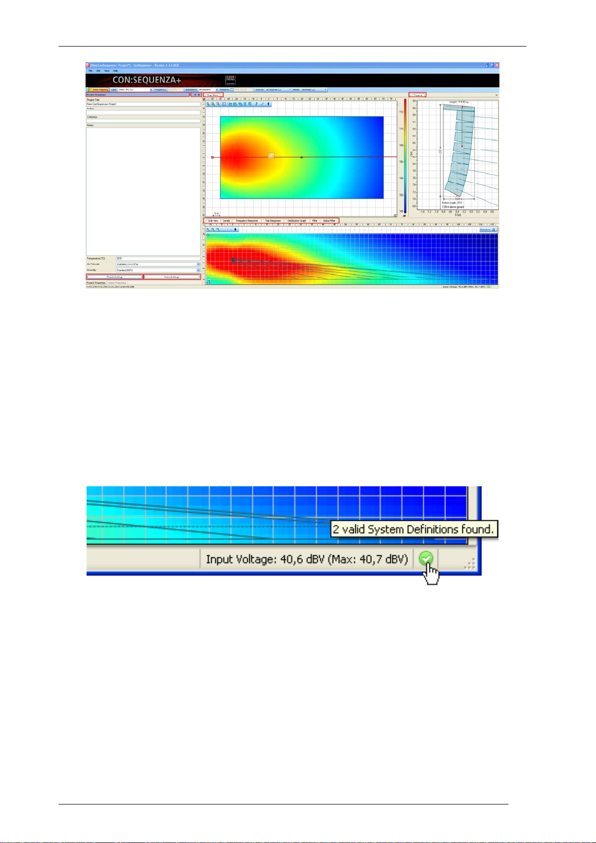
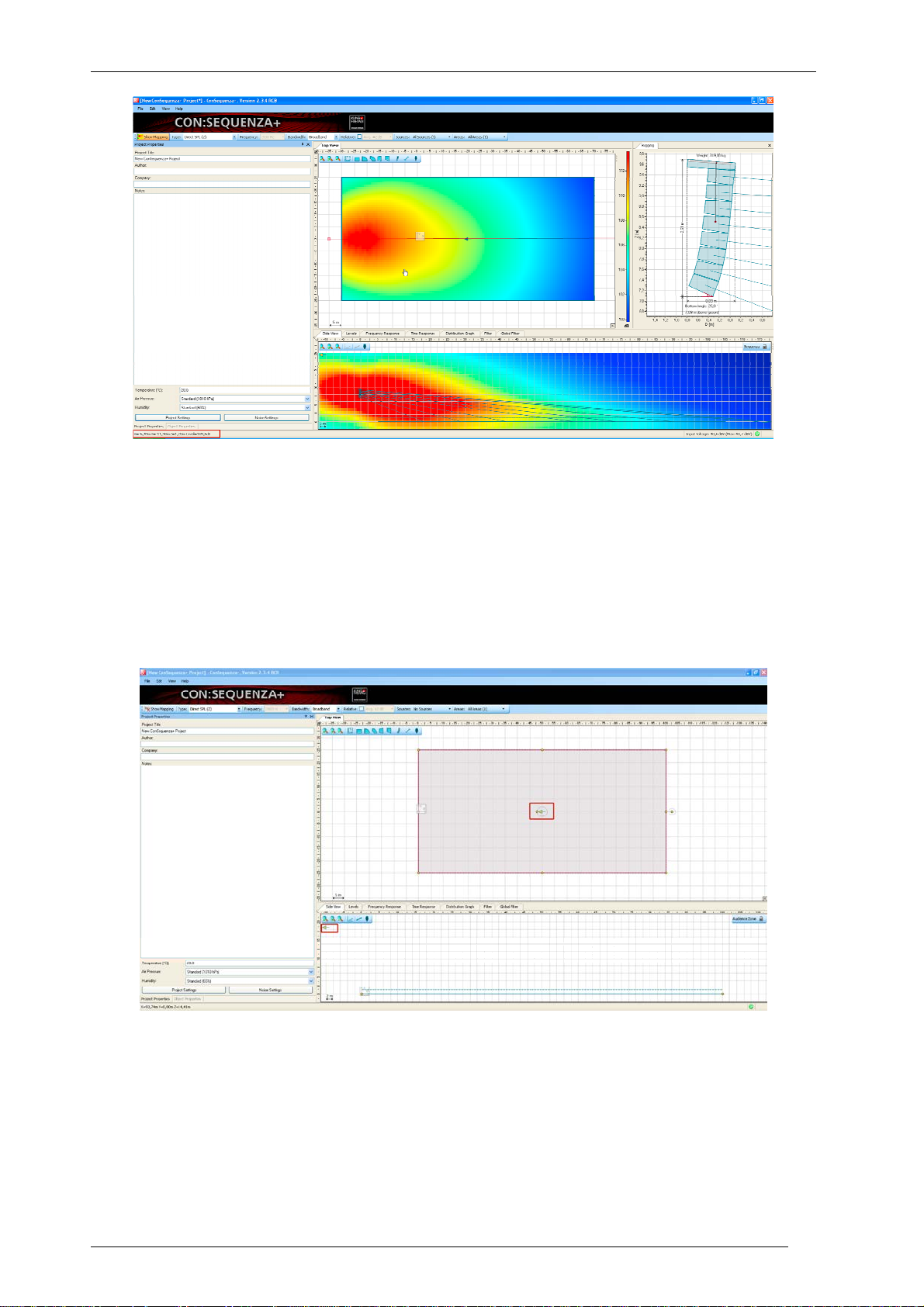
At the top of the main window you can find the menu bar, a panel displaying the Mapping
Toolbar (§3.1).
At the bottom is the status bar. On its left side readouts for mouse position are shown as you
navigate maps and graphs of many windows (see §1.5 for more). On its right side you find the
input voltage for the selected Sound Source (§3.2), error and warning count relative to Sound
Sources (§2.11) and Audience Zones (§2.5), and an icon showing the status of system definitions
(it should be green, if there is no error; red otherwise). Clicking on the errors and warnings you
can open a window listing them in detail; clicking on the system definitions status icon you can
restart scan or open Environment options (§4.3).
Note that you can move windows by grabbing their title bar or tab caption. You can also change
their size relative to the other windows. Use the command View | Reset Layout to return to the
original settings. Use the Store and Restore commands in the View menu to create and recall your
own window layouts.
KLING & FREITAG GmbH Version 1.0 Seite 7 von 53
Page 8
User’s Guide K&F CON:SEQUENZA+
1.5 Program Conventions
1.5.1 Definition of Terms
There are four major types of objects in CON:SEQUENZA+:
• Audience Zones (§2.4): Audience Zones are two-dimensional shapes roughly circumscribing
the audience in one direction when looking from the stage. They contain one or more
Audience Areas (§2.5). An Audience Area is always part of a Zone; it is defined by starting
and ending points and is stretched out over the width of the Zone: this is the actual area
where the audience is located.
• Sound Source: Based on the related system definition (GLL), a Sound Source consists of one
or multiple point sources each of which is considered the origin of a sound wave.
Technically, a Sound Source can be one of two types, either a K&F Line Array (§2.10) or a
K&F Loudspeaker (§2.14). Depending on the properties of the Sound Source, the respective
GUI elements may be different.
• Receiver (§3.6): A Receiver is a representative point for detailed acoustic analysis, such as
with respect to the local time or frequency response. This item has no acoustic relevance.
• Section Plane: A Section Plane is a user-defined, virtual surface that can be added to the
project in order to view mapping data in an arbitrary vertical cutting plane (see §5.2). Like
the Receiver, this item is purely virtual and has no effect on the computational results.
A Project is the set of all objects as defined before combined with the settings associated with the
project such as regarding height limits or noise levels. Projects can be loaded from and saved to
files with the extension .cs+.
1.5.2 Coordinate System
The main coordinate system in CON:SEQUENZA+ uses XYZ coordinates. The origin marker is
displayed by default in the Top View (but can be hidden, see §4.1) and can be moved to another
location (§5.6). XYZ coordinates are used in the Object Properties window to indicate the position
of all objects. The current mouse location in Top View, Side View and Rigging windows is shown
in the status bar, along with the SPL value at that point, if an active Sound Source exists. For all
other windows that display a plot you can also see current mouse coordinates in the status bar.
KLING & FREITAG GmbH Version 1.0 Seite 8 von 53
Page 9
User’s Guide K&F CON:SEQUENZA+
Another important coordinate system is DZ coordinates, used in Side View, Rigging and Levels
windows. The DZ origin marker can be optionally hidden in Side View as well. While Z still refers to
the elevation from the ground, D is relative to the position of the object whose section is displayed
in Side View, and reflects the distance, along the object’s main axis, from its reference point: the
location for Sound Sources (§2.10, §2.14) and Receivers (§3.6), the front center point for
Audience Zones (§2.4), or the starting point for Section Planes (§5.2). You can see how relative D
values relate to XY coordinates in the status bar, while you move your mouse over Side View,
Rigging and Levels windows.
The difference between positive and negative D values is given by a simple convention: in short,
Sound Sources are expected to be radiating from left to right in Side View, and the audience is
expected to face from right to left. For this reason, the Side View relative to Sound Sources is
always showing them pointing right, while relative to Receivers, Audience Zones and Section
Planes it shows them pointing left. If you have any doubt when using Audience Zones or Section
Planes, refer to the yellow arrow appearing in the middle of those objects when they are selected,
and pointing to their front center point (for Audience Zones) or starting point (for Section Planes):
KLING & FREITAG GmbH Version 1.0 Seite 9 von 53
Page 10

User’s Guide K&F CON:SEQUENZA+
this is the same arrow that appears in the Side View, pointing left, and these two arrows are
oriented in the same direction.
1.6 Shortcut List
Here is a list of all keyboard shortcuts available in CON:SEQUENZA+, for quick reference.
Main window (always active):
F1 Help; opens this User’s Guide
F4 Show Object Properties or Object List
F9 Options (see Chapter 4)
F10 Scale to Fit (both Top View and Side View)
F11 Select Previous Object
F12 Select Next Object
Ctrl+N New Project
Ctrl+O Open Project (§2.8)
Ctrl+S Save Project (§2.7)
Ctrl+Shift+S Save Project As (§2.7)
Ctrl+Z Undo
Ctrl+Y Redo
Ctrl+Alt+L Add Sound Source (§2.10, §2.14)
Ctrl+I Import System Definition (§2.9)
Ctrl+T Change System (when a Sound Source is selected)
Ctrl+Shift+J J-Array setup (when a Line Array is selected, see §2.11)
Ctrl+Shift+L Lined setup (when a Line Array is selected, see §2.11)
Ctrl+Shift+C Curved setup (when a Line Array is selected, see §2.11)
KLING & FREITAG GmbH Version 1.0 Seite 10 von 53
Page 11
User’s Guide K&F CON:SEQUENZA+
Ctrl+Shift+A Auto Splay (when a Line Array is selected, see §2.12)
Ctrl+F1 …
F12
Activate a stored layout: individual layout names and shortcuts can be seen in
the View menu (§1.4)
Ctrl+Alt+C The automatic mapping color legend is by default optimized for Top View: use
this shortcut to switch optimization between Top View and Side View
Top View (§2.2):
Ctrl+C Copy selected object
Ctrl+V Paste copied object
Ctrl+Shift+C Copy Areas (for Audience Zones, see §2.6), Copy Setup (for Sound Sources, see
§2.13)
Ctrl+Shift+V Paste Areas (for Audience Zones, see §2.6), Paste Setup (for Sound Sources, see
§2.13)
Del Delete selected object
Modifier keys (to be held while performing a mouse action):
Shift Measure distance (when dragging between two points in Top View or Side View)
Alt Ignore snapping in Top View and Side View (see §4.2 about snap settings)
Ctrl Free the Receiver currently being edited, ignore auto-anchoring (§3.6)
KLING & FREITAG GmbH Version 1.0 Seite 11 von 53
Page 12
User’s Guide K&F CON:SEQUENZA+
2 Venue Definition and Line Arrays
This section gives a brief introduction into the main features you need to know in order to model a
small project with CON:SEQUENZA+. We will explain how to enter a simple venue and then add a
Sequenza line array system to it. More advanced topics will be covered in the subsequent chapters.
The next chapters will guide you through the main steps of editing a project. Whenever you make
a mistake, you can revert any modification to the project, or recover a reverted modification, with
the menu items Edit | Undo (Ctrl+Z) and Edit | Redo (Ctrl+Y).
In this chapter and in the following ones you will find some yellow frames along the way, just
like this one. These contain simple examples to help you learn how to use CON:SEQUENZA+.
You can choose to create your own project, or to work on this tutorial project and learn as
you progress.
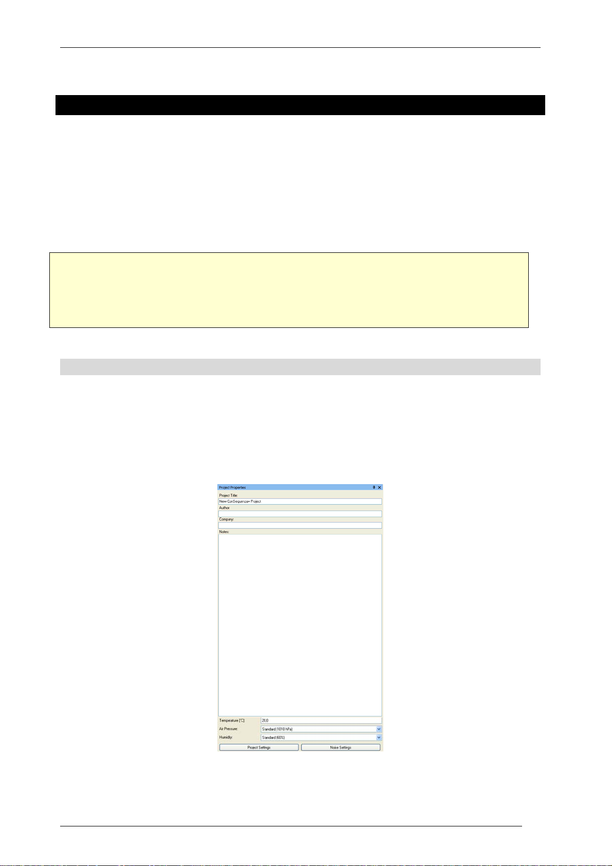
2.1 Project Properties
The Project Properties window is located on the left side of the main window. It contains basic
information about the project (title, company, author, notes) as well as some settings that are
relevant for calculations (temperature, air pressure, humidity).
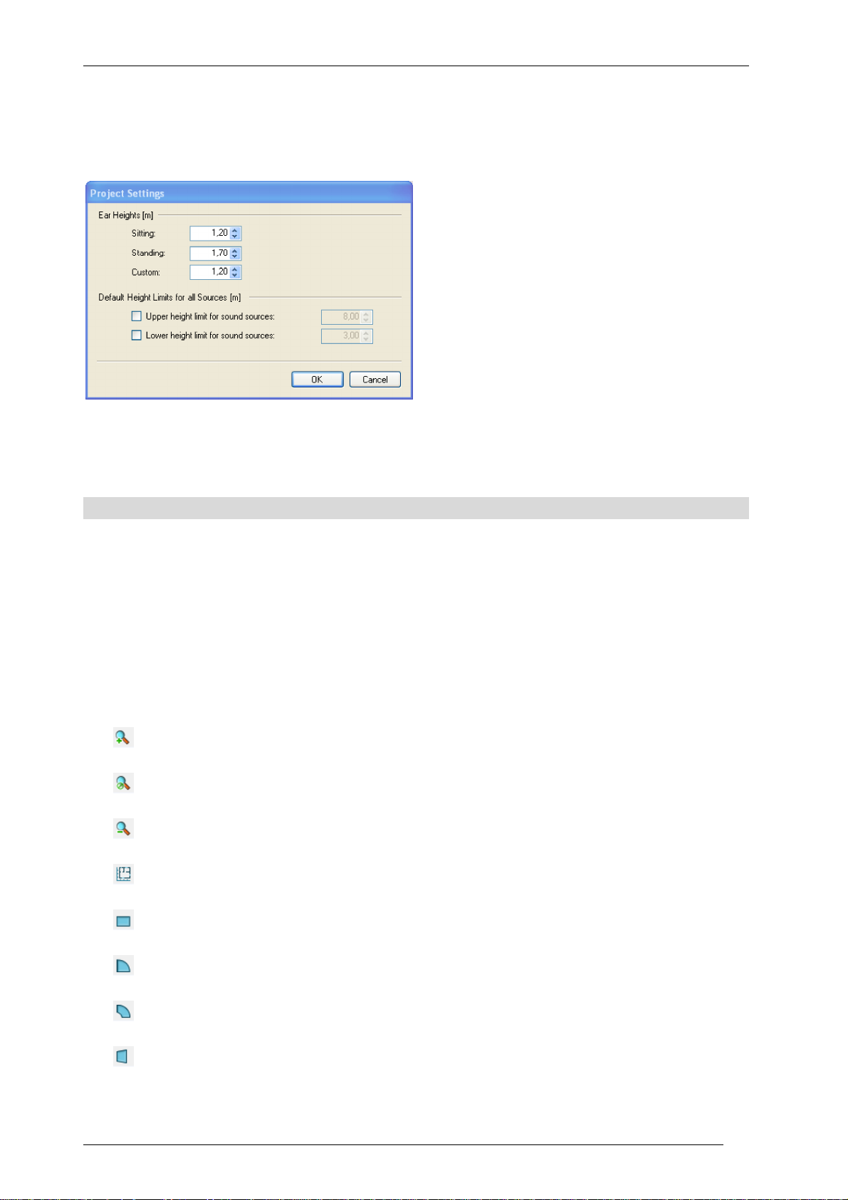
From here you can also access the Project Settings window, where you can edit ear height values
for Audience Areas. Three values are available: Sitting, Standing and Custom. When editing
KLING & FREITAG GmbH Version 1.0 Seite 12 von 53
Page 13
User’s Guide K&F CON:SEQUENZA+
Audience Zones, you will be able to choose one of these values for each Area (§2.5). In the Project
Settings window you can also define default project-wide height limits for Sound Sources. When
editing a Source you can choose whether to apply project limits or to define individual limits
(§2.11).
When working in Extended mode, you can access the Noise Settings from a button within the
Project Properties window as well (§5.7). See §4.3 to learn how to activate Extended mode.
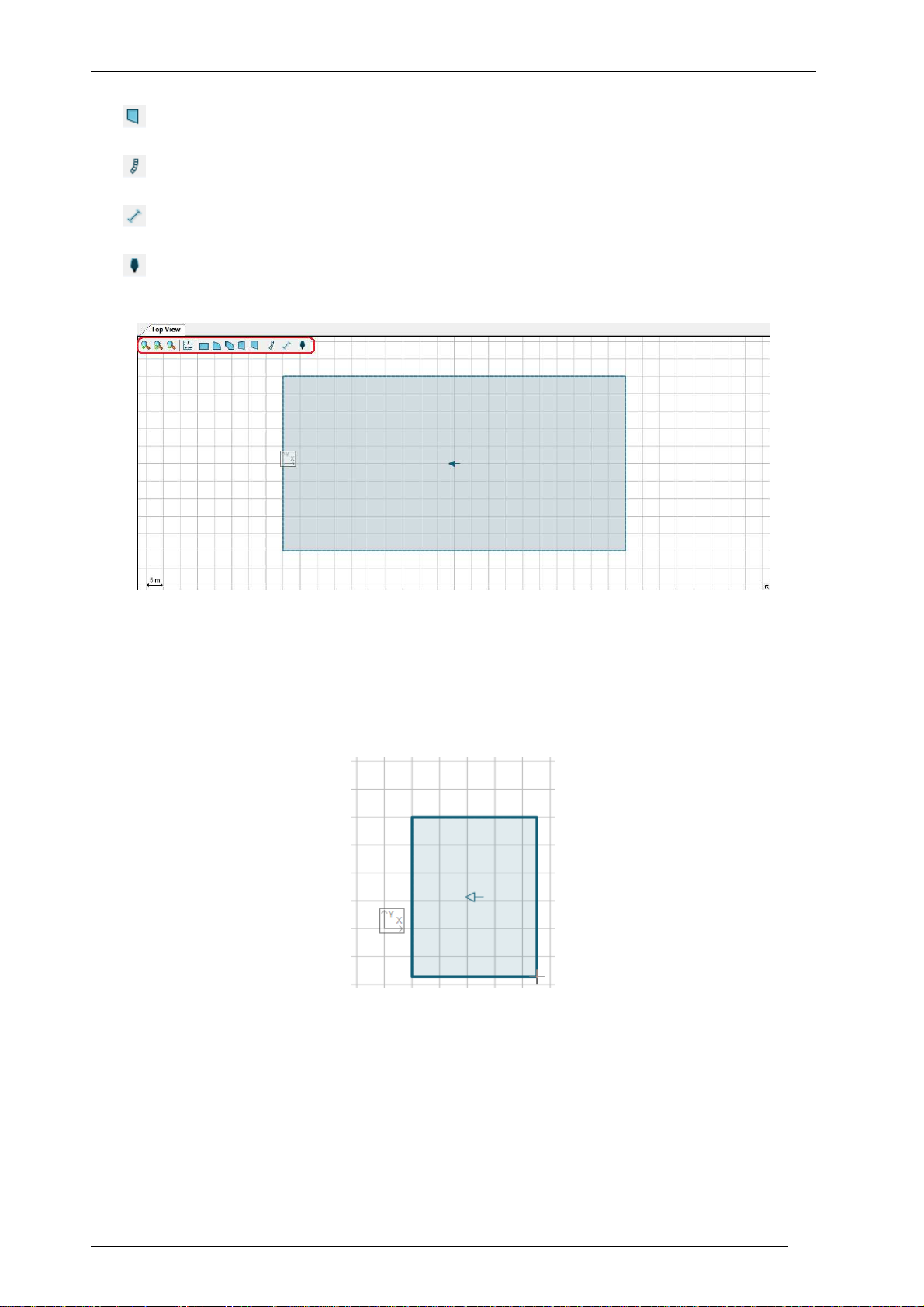
2.2 Top View
The Top View displays a plan of the venue, and contains all objects in the project: Audience Zones,
Sound Sources, Receivers and Section Planes. To select an object, click on it with the left mouse
button; to move it, just drag it around the window. In addition, objects have either aiming lines
(Sound Sources and Receivers) or yellow handles (Audience Zones, Section Planes) to rotate them
and resize them with a simple mouse drag.
The Top View toolbar is located on the top left corner of this window. It includes the following
buttons:
Zoom in
Fit the zoom to the project
Zoom out
Add Layout Picture (§5.1)
Add Audience Zone (Rectangle) (§2.4)
Add Audience Zone (Circular Sector) (§2.4)
Add Audience Zone (Annular Sector) (§2.4)
Add Audience Zone (Trapezoid) (§2.4)
KLING & FREITAG GmbH Version 1.0 Seite 13 von 53
Page 14
User’s Guide K&F CON:SEQUENZA+
Add Audience Zone (Right-Angled Trapezoid) (§2.4)
Add Sound Source (§2.10, §2.14)
Add Section Plane (§5.2)
Add Receiver (§3.6)
To add an object, first click on the button in the toolbar corresponding to the desired object. Then
move the mouse to the desired location in the drawing, click the left button and drag with your
mouse until you are satisfied with the size and orientation of the object. If you click without
dragging, the object will be centered on mouse location and take on the default size and
orientation, which you can then modify later.
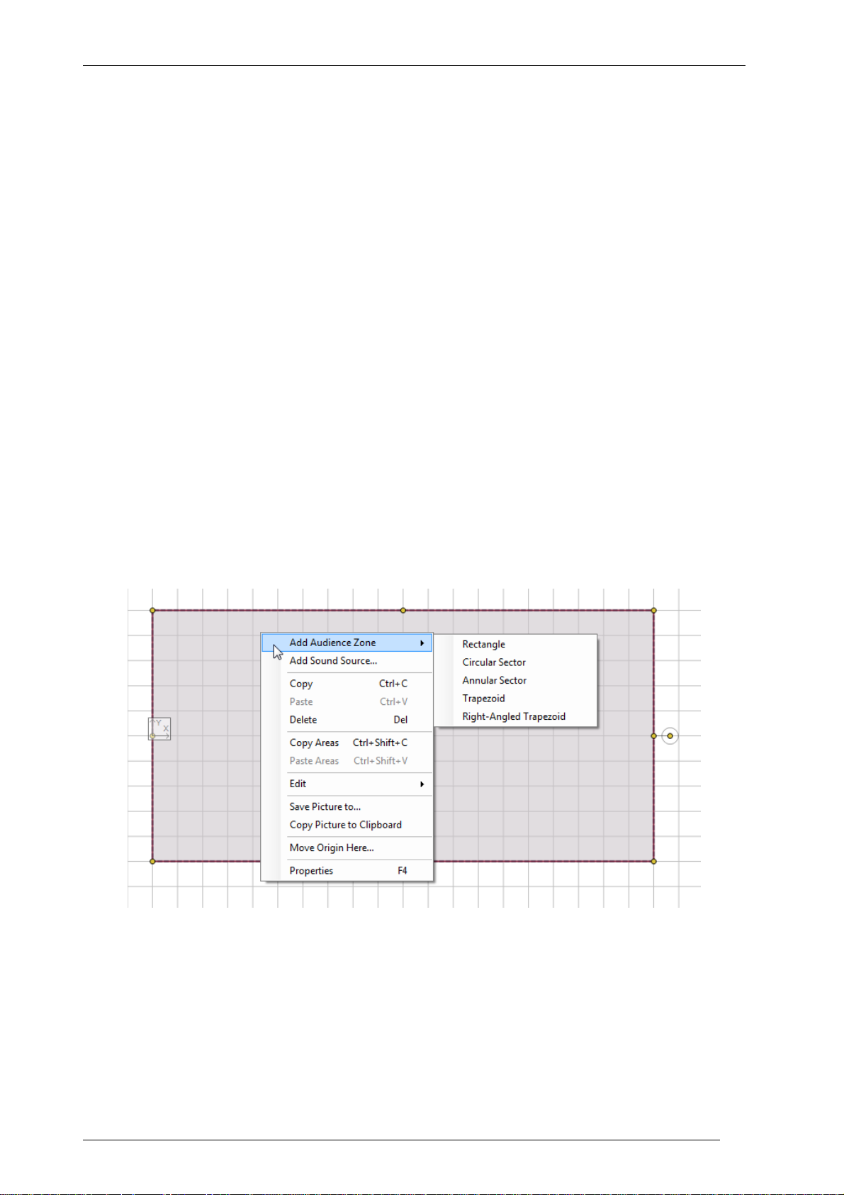
Clicking anywhere in the Top View with the right mouse button will open the context menu,
where you can perform any of the following actions:
• Add Audience Zone: inserts a new Audience Zone into the Project (Rectangle, Circular
Sector, Annular Sector, Trapezoid, Right-Angled Trapezoid), as an alternative method to
the toolbar buttons (§2.4).
• Add Sound Source: inserts a Line Array (§2.10) or a Loudspeaker (§2.14) into the Project,
as an alternative method to toolbar buttons.
• Copy (Ctrl+C): copies the selected object to the clipboard.
KLING & FREITAG GmbH Version 1.0 Seite 14 von 53
Page 15
User’s Guide K&F CON:SEQUENZA+
• Paste (Ctrl+V): pastes any previously copied object into the Project.
• Delete (Del): removes the selected object.
• Copy Areas (Ctrl+Shift+C): when an Audience Zone is selected, stores its Audience Areas to
be subsequently applied to another Audience Zone (§2.6).
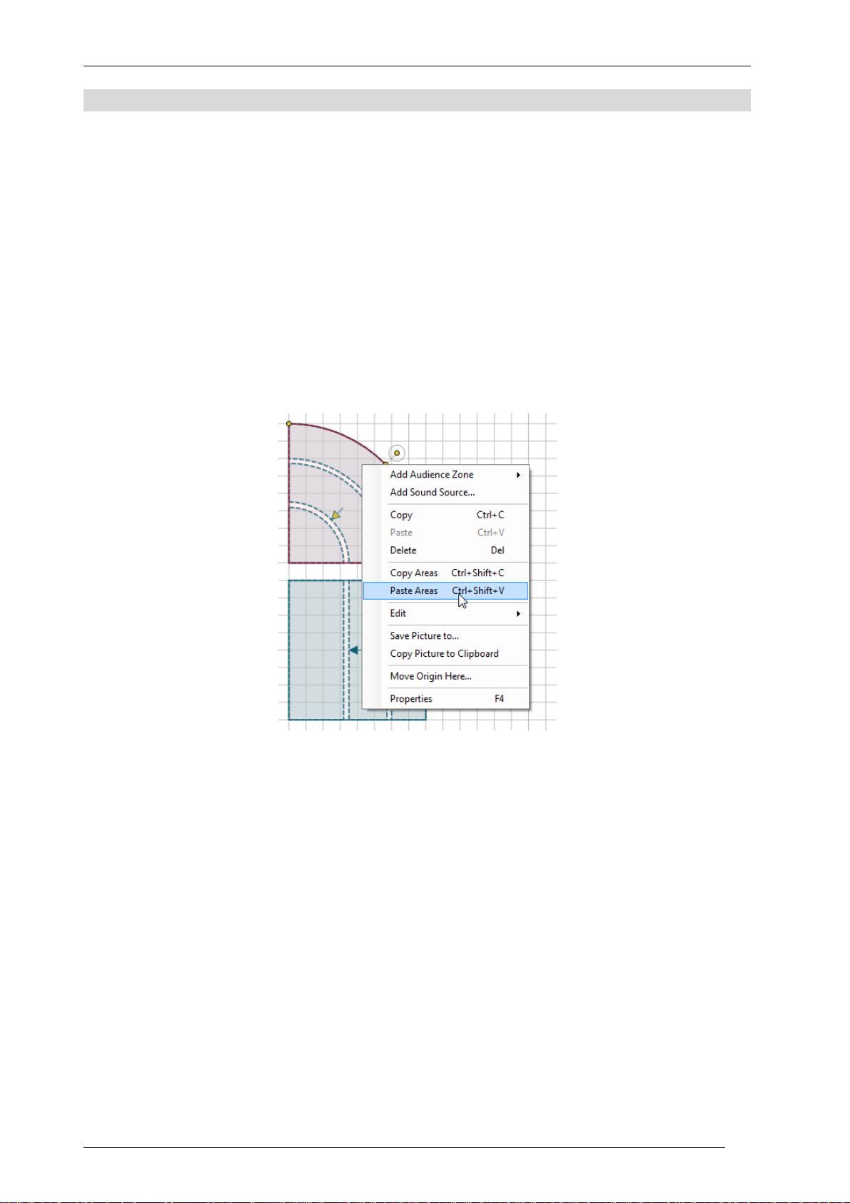
• Paste Areas (Ctrl+Shift+V): when an Audience Zone is selected, and Audience Areas have
been copied from another Zone, pastes them to the selected Zone (§2.6).
• Copy Setup (Ctrl+Shift+C): when a Sound Source is selected, stores its setup to be
subsequently applied to a compatible Source (§2.13).
• Paste Setup (Ctrl+Shift+V): when a Sound Source is selected, and a setup has been copied
from a compatible Source, applies it to the selected Source (§2.13).
Please note that copying objects, copying Audience Areas and copying Sound Source setups are
three independent functions that do not override or affect each other. However, copying objects
and copying pictures (see below) both use the Windows clipboard, and will override each other.
• Edit: performs an action affecting the selected object. You can Flip Horizontally, Flip
Vertically, Rotate Clockwise, Rotate Counterclockwise.
• Save Picture to: saves the content of the Top View as an image file (§3.10).
• Copy Picture to Clipboard: copies the content of the Top View as an image in the Windows
clipboard, to be pasted into any Windows application that supports it.
• Move Origin Here: specifies a new origin for the Project coordinates (§5.6).
• Properties (F4): when an object is selected, shows the Object Properties window for that
object if it is hidden and brings it to the top.
• Object List (F4): when no object is selected, shows the object list if it is hidden and brings it
to the top.
Note that all drawing and editing options snap by default to the displayed grid; this can be
changed in the options (§4.2). Holding the Alt key will also temporarily deactivate the snap to the
grid. Holding the Shift key before dragging with the mouse will measure any distance in length
and time delay.
KLING & FREITAG GmbH Version 1.0 Seite 15 von 53
Page 16
User’s Guide K&F CON:SEQUENZA+
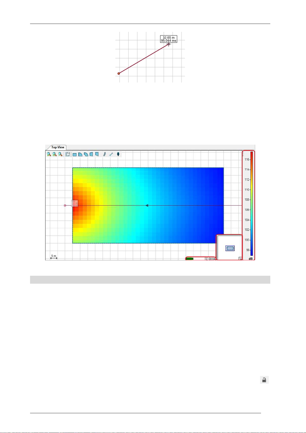
On the bottom right corner you can see a miniature map of the whole project, displaying the
portion currently being viewed: this small frame can be collapsed if you don’t need it. To the left of
it, a Mapping Progress Bar will appear whenever mapping data are being calculated. The Mapping
Legend appears by default on the right edge of the Top View whenever color mapping is active
and visible, but it can also be collapsed by clicking on the three small triangles in the upper left of
its window.
2.3 Side View
The Side View has an interface similar to the Top View, except it will not show the whole project,
but only a vertical section of it, referring in general to the selected object. The section is taken
along the central axis of the object: for Audience Zones this is the line going through the
orientation arrow displayed in the Top View, for Sound Sources and Receivers it is the aiming line,
and for Section Planes the plane itself.
To understand in which direction you are looking when an Audience Zone or a Section Plane is
selected, use the yellow arrow in the top left corner: it replicates the arrow appearing on these
two types of objects when they are selected, and points in the same direction. When a Sound
Source is selected, the Side View displays it to the left, with the aiming line oriented rightwards;
the aiming line points leftwards instead, in the case of Receivers.
You can also see the related Side View of an object which is not selected. Use the Lock symbol
in the upper right corner of the Side View window to keep the side view of an object while
manipulating another one. This is helpful, for example, when you want to adjust the location of a
KLING & FREITAG GmbH Version 1.0 Seite 16 von 53
Page 17

User’s Guide K&F CON:SEQUENZA+
Receiver in the Side View of a Line Array or change the splay angles of a Line Array while viewing
an audience zone.
Just like the Top View, the Side View has its toolbar in the top left corner as well. It displays these
buttons:
Zoom in
Fit the zoom to the project
Zoom out
Add Layout Picture (when an Audience Zone or a Section Plane is being displayed) (§5.1)
Add Audience Area (when an Audience Zone is being displayed) (§2.5)
Add Receiver (§3.6)
A Mapping Progress Bar will appear in the bottom right corner whenever mapping data are being
calculated.
The Side View window is particularly useful to edit Audience Zones (§2.6), Line Arrays (§2.11) and
Loudspeakers (§2.14) with a graphical interface.
2.4 Adding Audience Zones
Audience locations are defined on two levels. First, Audience Zones are entered in the Top View
and should include all particular seating areas in one direction looking towards the center or stage
of the venue. In a second step, a profile consisting of one or multiple Audience Areas is defined for
each Zone.
KLING & FREITAG GmbH Version 1.0 Seite 17 von 53
Page 18
User’s Guide K&F CON:SEQUENZA+
A Zone is basically a simple 2D shape that can be understood as the circumjacent projection of the
seating areas in one part of the venue on the horizontal plane. It is defined by a location,
orientation and properties specific to the shape, such as the width and depth of a rectangle.
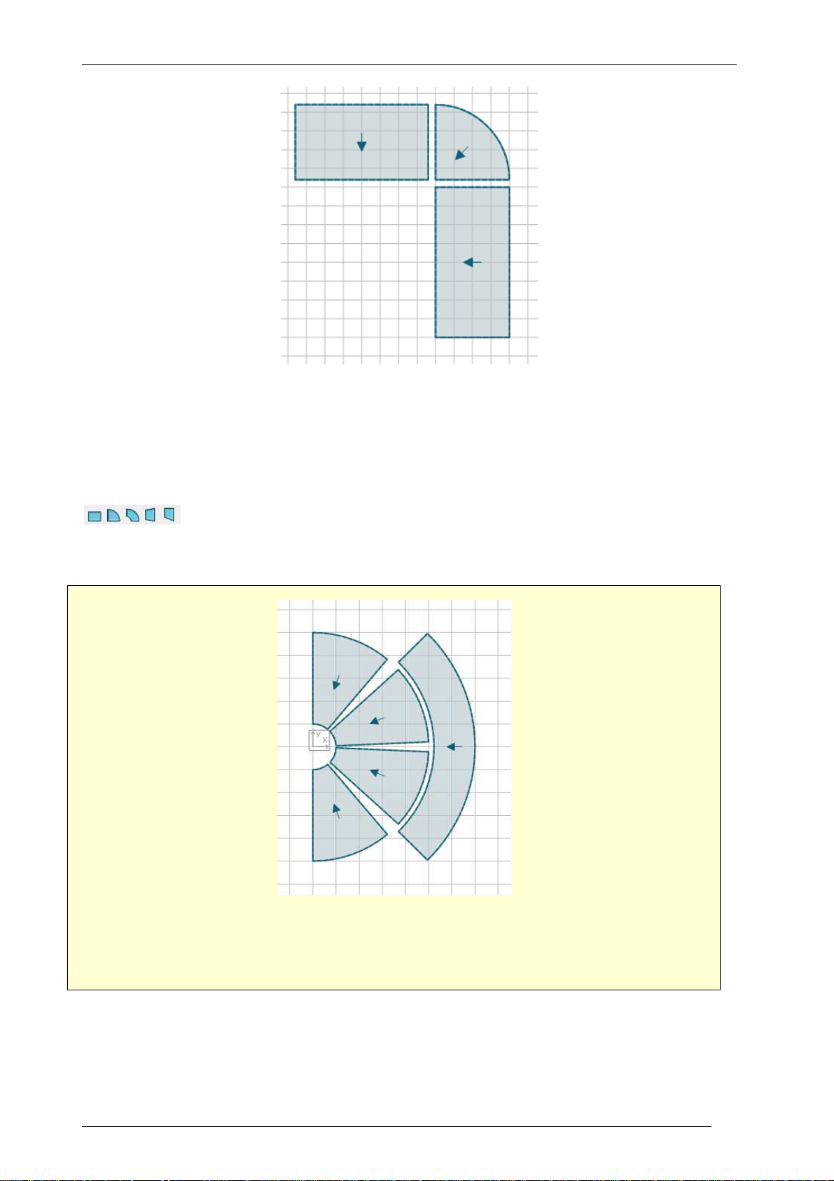
Use the shape icons in the top view to select a particular shape for insertion:
Then add an Audience Zone by clicking or dragging.
Draw an amphitheater similar to the one shown above. You will need five Annular Sectors.
Give them meaningful names like “Floor Left”, “Floor Middle Left”, “Floor Middle Right”,
“Floor Right”, “Balcony”.
KLING & FREITAG GmbH Version 1.0 Seite 18 von 53
Page 19

User’s Guide K&F CON:SEQUENZA+
2.5 Editing Audience Zones
Select a Zone by simple left-click.
When active, the Zone will be highlighted in dark red. It will also show yellow handles that allow
you to resize, rotate or change the shape of the Zone. A Zone can be moved relative to other
objects by simply left-dragging it with the mouse. The yellow arrow (blue when the Zone is
deselected) indicates the viewing direction of the spectators.
An Audience Area is always part of a Zone and is defined by a starting point and an ending point
relative to the Zone. There can be multiple Areas inside a Zone. In 3D, these Areas are assumed to
be stretched out over the width of the entire Zone, depending on the symmetry of the shape.
Selecting a Zone will show the Zone’s profile in the side view.
KLING & FREITAG GmbH Version 1.0 Seite 19 von 53
Page 20

User’s Guide K&F CON:SEQUENZA+
Use the line icon to enter a new Area for this Zone. Note that you can also left-drag the yellow
handles at the ends of an Area to resize it or left-drag the center of an Area to move it. Left-drag
the white background of the drawing to move the objects relative to the screen.
The horizontal dotted line at the bottom of the Side View indicates the Audience Zone. The
Audience Zone above consists of three Audience Areas denoted by the solid lines with the yellow
handles. The dotted lines that are parallel to the Audience Areas indicate the selected listening
heights.
KLING & FREITAG GmbH Version 1.0 Seite 20 von 53
Page 21

User’s Guide K&F CON:SEQUENZA+
Properties of Audience Zones can also be modified from the Object Properties window. Below is a
short description of all Audience Zone types and of the attributes available for each one.
Rectangle: a rectangular Zone, with the audience facing one of the edges
• Orientation: the direction the Audience Zone is facing (0° = facing left)
• Depth: the size of the Zone along its axis
• Width: the size of the Zone across its sides
• Front Center, Front Left, Front Right, Back Left, Back Right: position of the main reference
points
Circular Sector: a Zone whose shape is a circular sector (like a piece of pie), with the audience
facing the corner point
• Orientation: the direction the Audience Zone is facing (0° = facing left)
• Depth: the size of the Zone along its axis
• Sweep Angle: the angular width of the sector
• Front Center, Back Left, Back Right: position of the main reference points
Annular Sector: a Zone whose shape is an annular sector (a portion of a ring), with the audience
facing the center of the circle
• Orientation: the direction the Audience Zone is facing (0° = facing left)
• Depth: the size of the Zone along its axis
KLING & FREITAG GmbH Version 1.0 Seite 21 von 53
Page 22

User’s Guide K&F CON:SEQUENZA+
• Inner Radius: distance between the inner circle and the center of the circle (outer radius =
inner radius + depth)
• Sweep Angle: the angular width of the sector
• Front Center, Front Left, Front Right, Back Left, Back Right: position of the main reference
points
Trapezoid: a Zone whose shape is an isosceles trapezoid, with the audience facing one of the
parallel edges
• Orientation: the direction the Audience Zone is facing (0° = facing left)
• Depth: the size of the Zone along its axis
• Front Width: the size of the parallel edge faced by the audience
• Back Width: the size of the parallel edge behind the audience
• Front Center, Front Left, Front Right, Back Left, Back Right: position of the main reference
points
Right-Angled Trapezoid: a Zone whose shape is a right-angled trapezoid, with the audience
facing one of the parallel edges
• Orientation: the direction the Audience Zone is facing (0° = facing left)
• Depth: the size of the Zone along its axis
• Front Width: the size of the parallel edge faced by the audience
• Back Width: the size of the parallel edge behind the audience
• Orthogonal Side: specifies which of the two non-parallel edges is orthogonal with respect
to the parallel edges (left or right, with respect to the audience)
• Front Center, Front Left, Front Right, Back Left, Back Right: position of the main reference
points
Audience Areas can even be added or removed from the Object Properties window, and their
profile can be copied to other Zones (§2.6). For every Audience Area you can set the following
attributes:
• D1: distance between the front side of the Area and the front side of the Zone
• D2: distance between the back side of the Area and the front side of the Zone
• Z1: height of the front side of the area
• Z2: height of the back side of the area
• Length: size of the Audience Area along its axis (diagonal, accounting for height difference
between front and back)
• Tilt: angle between the Audience Area and the horizontal plane
• Ear Height: ear height of the audience, selected from three pre-defined values (see §2.1)
Note that D2 / Z2 and Length / Tilt are redundant. If you change one of the numbers, the program
will automatically compute the other quantities.
If two Audience Areas intersect, error messages will be shown, both in the Audience Zone related
Object Properties and Side View and in the status bar.
KLING & FREITAG GmbH Version 1.0 Seite 22 von 53
Page 23

User’s Guide K&F CON:SEQUENZA+
Select one of the floor Audience Zones that you have entered in the previous section, and
draw three Audience Areas in it, as shown in the picture. These will be the levels of the
amphitheater. Name the Areas “Top Level”, “Middle Level” and “Bottom Level.” In the next
paragraph we will see how to extend levels to other Audience Zones.
KLING & FREITAG GmbH Version 1.0 Seite 23 von 53
Page 24
User’s Guide K&F CON:SEQUENZA+
2.6 Copying Areas between Zones
You might find yourself drawing a venue where several Audience Zones have a similar profile. A
typical example is a stadium where all Zones could form a loop consisting of rectangles, annular
and circular sectors, but circles extend across all these Zones. The solution for this situation is the
“Copy Areas” operation. It can be performed in two ways:
• Context menu in Top View: the Audience Areas must of course be defined for one of
the Audience Zones. Then click with the right mouse button on that Zone: a menu will
appear. Select the item Copy Areas; then right click on one of the target Zones and select
Paste Areas. Repeat this operation for all target Zones (you do not have to re-copy Areas
every time, as they will be kept in memory until they are overwritten by another Copy
Areas operation).
• Object Properties window: once you have defined the Audience Area profile for one
Zone, when this is selected, open the Object Properties window (if it is not showing
already: either from menu View | Object Properties, or right clicking in the Top View and
selecting Properties, or just hitting F4) and click on the Copy Areas to Other Zones button.
A dialog will appear listing all Audience Zones in the Project; click on any of them in the list
to identify it in the Top View. Check all target Zones for your copy operation. Additional
options on Area groups are available in the expandable section on the bottom (§3.9). Click
OK to validate the selection and run the operation.
KLING & FREITAG GmbH Version 1.0 Seite 24 von 53
Page 25

User’s Guide K&F CON:SEQUENZA+
Please note that copied Areas will be adapted to the size of target Zones. However, if your
Audience Zones have about the same length, no unexpected results will happen.
Make sure that all your floor Zones have the same depth, as it is logical in an amphitheater.
Then select the Zone in which you have drawn the levels, and copy them to all other floor
Audience Zones. Try both methods to do so.
2.7 Saving Projects
To save a project, click on File | Save (Ctrl+S); File | Save As (Ctrl+Shift+S) will save the current
project to a new file, similar to most other programs. Saving a project will also pack GLL and DLL
files into the file, so that it can be passed on to other CON:SEQUENZA+ users without having to
worry about updated or new files that are needed to open it. However, note that this could lead
to quite large project files.
KLING & FREITAG GmbH Version 1.0 Seite 25 von 53
Page 26

User’s Guide K&F CON:SEQUENZA+
When a project is modified after saving, a star (*) symbol will appear next to its file name in the
main window title bar. This indicates that the current project contains unsaved changes. In this
case, if you try to quit CON:SEQUENZA+, you will be asked if you want to save all changes. The
same is true for new projects.
2.8 Loading Projects
To load a project, click on File | Open (Ctrl+O). Before loading, if the project contains system
definitions, that is K&F GLL or K&F DLL files, that are not present on your hard disk, they will be
listed in the Import System Definitions window and you will have the possibility to save every single
file to a location of your choice. Alternatively you can click Save All, which will save all definition
files to the default system definitions location with their default name.
2.9 Importing System Definitions
Besides loading a project, there is another way to add compatible system definitions to the
CON:SEQUENZA+ database. If you have one or more GLL files which are compatible with
CON:SEQUENZA+ you can click Edit | Import System Definition Files: this will open a dialog
window where you can select one or more GLL files. After that, all valid sound sources will be
listed in the Import System Definitions window where you have the same options described in
§2.8.
2.10 Adding Line Arrays
To enter a K&F Line Array or other kind of K&F Sound Source use the insert icon or use the
RMB menu that opens when right-clicking the white background of the drawing.
This will bring up a list of available Sound Source types. Select one of them and then left-click or
drag to insert it into the top view.
KLING & FREITAG GmbH Version 1.0 Seite 26 von 53
Page 27
User’s Guide K&F CON:SEQUENZA+
Add two Line Arrays pointing towards the two middle floor Audience Zones, as shown in the
picture. You can name them after the zones where they are aimed.
2.11 Editing Line Arrays
In the Top View you can change the location of a Line Array by left-dragging the symbol; or its
orientation by left-dragging the aiming line. You can do the same in the Side View, where you can
also edit the height of the Array and the tilt angle of the single boxes using their aiming lines.
KLING & FREITAG GmbH Version 1.0 Seite 27 von 53
Page 28

User’s Guide K&F CON:SEQUENZA+
The same parameters can be fine-tuned in the Object Properties window, where you can define
the following attributes:
• Setup: lets you choose between setups. A setup can be hanging (flown) or ground stacked
• X, Y, Z: coordinates of the array’s reference point
• Ver: vertical tilt angle of the frame
• Hor: horizontal aiming angle of the Line Array (0° = pointing right)
• Height Limits: height limits for the current Line Array. Limits can be set to Project default
(§2.1) or individual for a specific Line Array.
In the Rigging frame you can also change the box number and types and edit the pinpoint mode:
you can set one or two pinpoints (manual) or define an angle and let CON:SEQUENZA+ find the
best fitting pinpoint (automatic). You can also access the Auto Splay function (§2.12) which can
help you defining an initial array configuration for a given venue.
There is also the button Filters. Selecting Filters, you will be able to simulate the effect of K&F
filters for specific elements of the line array (§5.4).
CON:SEQUENZA+ also supports Line Array presets: these can be applied under the menu Edit |
Line Array Presets; otherwise, only default presets (J-Array, Lined, Curved) will be available.
If static limits are violated, errors or warning messages will be shown in the window Errors &
Warnings.
2.12 Auto Splay
The Auto Splay function is a valuable tool of CON:SEQUENZA+ that can save you a lot of time
when starting to set up your system. Auto Splay optimizes SPL levels produced by the Line Array
KLING & FREITAG GmbH Version 1.0 Seite 28 von 53
Page 29

User’s Guide K&F CON:SEQUENZA+
along its aiming axis, on the Audience Areas that are crossed by it. Levels are calculated at ear
height.
However, note that Auto Splay will only give you a starting point for your system configuration.
To use Auto Splay, select the Line Array, go to the Object Properties (F4) and click on Auto Splay.
A dialog window will show, making options available about the boxes to be considered. One
additional expandable section of the dialog window can be used to select Audience Areas to be
optimized.
Another section can be used to define the Auto Splay strategy:
• conventional (default) runs the CON:SEQUENZA+ Auto Splay algorithm with no constraints
• arcuate applies a constant opening angle between adjacent boxes, if possible
• spiral applies a constantly increasing opening angle between adjacent boxes, if possible.
KLING & FREITAG GmbH Version 1.0 Seite 29 von 53
Page 30

User’s Guide K&F CON:SEQUENZA+
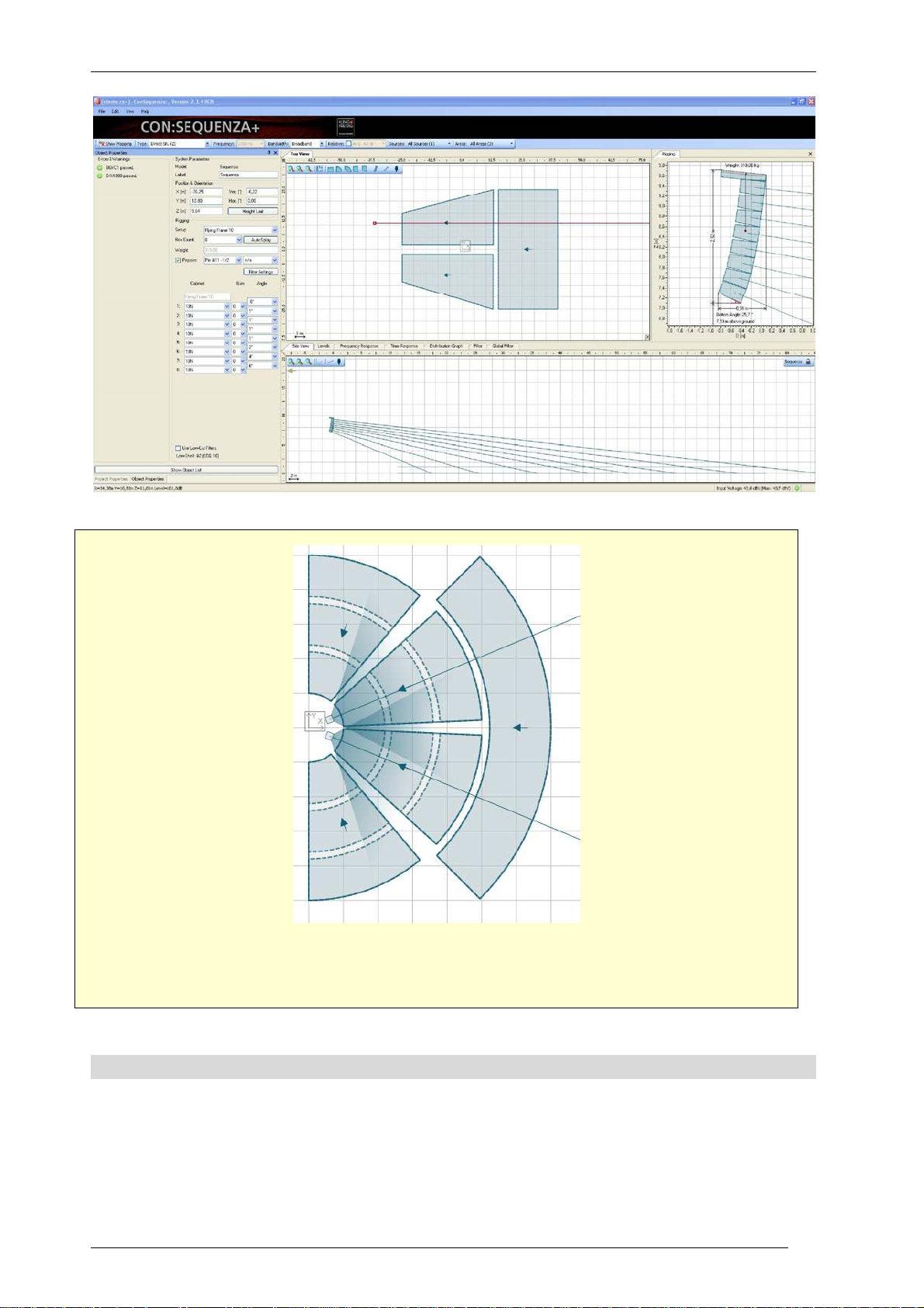
Select one of the two Line Arrays you have placed. Adjust its height, so that it is just above all
levels of the floor. Set the number of boxes to 8. Now perform an Auto Splay for all boxes
with all floor Audience Areas as the target (conventional strategy). Pay attention to exclude
the balcony from the optimization.
2.13 Copying Setups between Similar Line Arrays
In a situation where you have, for example, two Line Arrays in a stereo configuration, you may
have to make sure that they are identical. This is why the Copy Setup function exists. Similar to the
Copy Areas function between Audience Zones (§2.6), it can be performed in the following way:
The rigging must be defined for one of the Line Arrays. Then click with the right mouse button on
that Source, and select the menu item Copy Setup; then right click on each one of the target
Sources and each time select Paste Setup. A copied setup will be kept in memory until it is
overwritten by another “Copy Setup” operation.
Note that the copied information will include box count and types, tilt angles and filters along with
global tilt angle and height of the Line Array: this is all the information that has to do directly with
rigging setup. Horizontal angles and XY position will not be copied.
Setups can also be copied between Loudspeakers (§2.14): in this case, height and tilt angle will be
copied, along with all setup information internal to the loudspeaker library.
Copy the setup you created to the other Line Array.
KLING & FREITAG GmbH Version 1.0 Seite 30 von 53
Page 31

User’s Guide K&F CON:SEQUENZA+
2.14 Regular Loudspeakers
Besides the aiming of Sequenza line arrays, you can load and configure regular K&F loudspeakers,
as well. This is useful in order to account, for example, for the effect of down-fill or delay
loudspeakers in a complete model of the sound system in the venue.
All program functions that are available for line arrays are also available for regular loudspeakers.
The only difference is that the properties window for loudspeakers is much simpler than that for
line arrays. It allows entering the label of the sound source as well as its location and orientation. If
input configurations are defined by the system definition (GLL file), these can be selected in the
loudspeaker properties window as well.
KLING & FREITAG GmbH Version 1.0 Seite 31 von 53
Page 32

User’s Guide K&F CON:SEQUENZA+
3 Mapping and Calculation Results
This chapter explains how to exploit the calculation and mapping capabilities of CON:SEQUENZA+,
in order to have an optimal view of how your setup works in the field.
3.1 Mapping Toolbar
The Mapping Toolbar is located by default on top of the main window. This is the place where you
can edit the main parameters about how mapping is calculated and drawn.
To enable the SPL mapping display, select Show Mapping.
Use the Type dropdown menu to select the weighting (Z – none or A-weighting) or the Signal to
Noise mapping (only in Extended mode, see §4.3 on how to activate it; Noise Settings that are
defined will apply, see §5.7). Use the Frequency and Bandwidth dropdown menus to select the
kind of mapping to be shown, either broadband or band-limited (1/3 octave, 1 octave, 3 octaves)
and in the latter case the center frequency. You can use the Relative option and menu to highlight
areas whose pressure value lies outside a certain tolerance margin from the average value. Finally,
you can use the Source and Areas menus to select which Sound Sources and Audience Areas are
to be included in the mapping, and to store and recall Source groups (§3.8) and Area groups
(§3.9).
3.2 Calculations Background
All SPL calculations in CON:SEQUENZA+ are limited to the direct field. Also included in the
calculation are air attenuation effects according to ISO 9613. Shadowing and ground or side wall
reflections are not considered. Wind effects are also not taken into account.
KLING & FREITAG GmbH Version 1.0 Seite 32 von 53
Page 33

User’s Guide K&F CON:SEQUENZA+
CON:SEQUENZA+ is using a simplified model of treating combinations of sound sources. Elements
of a line array are always summed in a complex manner, which means that full signal coherence is
assumed. However, multiple line arrays are combined using power summation which is based on a
random-phase assumption.
The first assumption may overestimate pressure summation and cancellation effects among
elements of the array, especially for very tall systems and windy environments. But it has turned
out to be a good approximation in practice. The second assumption will underestimate the level of
coherence among several line arrays, especially at low frequencies or when they have the same
configuration and are placed very close to each other. Nevertheless, for most practical setups this
approximation is feasible.
Absolute SPL calculations in CON:SEQUENZA+ assume a broadband excitation with a signal that is
like program material. You can choose among three different types of input signal, see §3.3. Level
values displayed in the mapping or in the frequency response are sum levels. This representation is
equivalent to the readings one can take from real-time analyzers (RTA) and sound level meters
(SLM).
Note that in CON:SEQUENZA+ each sound source is always driven at its maximum input level. This
means that if you assign a gain of -6 dB to each cabinet of the array, the output SPL will be
unchanged. That is because the maximum input voltage is increased by 6 dB while the sensitivity
of the system is decreased by 6 dB. The only exceptions from this are the Filter and Global Filter
functions. They can be employed to adjust output levels of different arrays relative to each other.
The current input voltage and the maximum input voltage for the selected line array system are
shown in the status bar.
Be aware that the maximum input levels displayed in the software are only estimates based on the
specification and an ideal input signal. Just like the SPL prediction for the receive location these
results should be considered with care and are only accurate under the given limitations and
uncertainties.
Please keep in mind that CON:SEQUENZA+ is just a tool implementing an acceptable compromise
between ease-of-use, calculation speed and accuracy based on its main purpose of use.
3.3 Mapping Options
To access mapping options, select the menu File | Options or hit F9. Then select the Calculation
Parameters list item. Here you can choose the calculation resolution for your mappings: this will
affect the patch size of your calculations. Note that the number of points to be calculated
increases by about 10 times for every resolution level. Lower resolutions are computed first, and
their result displayed while higher resolutions are being processed. You can click on the mapping
progress bar located bottom right of Top View and Side View to read alternatively the remaining
time until the current resolution is completed or the total time until calculations are finished.
On the same page you can also edit the type of input signal to be played from Sound Sources (see
previous paragraph) and the accuracy of calculations (Fast Approximation will compute values with
an internal resolution of 1/3 octave, High Resolution will use an internal resolution of 1/24 octave).
KLING & FREITAG GmbH Version 1.0 Seite 33 von 53
Page 34

User’s Guide K&F CON:SEQUENZA+
If you select the Mapping Colors page, you will be able to choose between an automatic color
scale (default) or a scale constrained between values that you define. You can do this separately
for SPL and Signal-to-Noise mappings, and you can even choose to invert the scale with respect to
default colors.
You can also access this option page directly by clicking on the mapping scale on the right side of
the Top View or of the Side View.
KLING & FREITAG GmbH Version 1.0 Seite 34 von 53
Page 35

User’s Guide K&F CON:SEQUENZA+
3.4 Levels
If you need to check accurate level readings along one direction, you can use the Levels window
for that. It will consider exactly the same section that is used for the display in Side View, and show
all level lines on Audience Areas that intersect with it. If an Audience Zone is selected (or locked in
Side View), its Audience Areas are cut along the median axis; for Sound Sources, all Areas that
intersect with the aiming axis will be shown. The same holds for Receivers (§3.6) and Section
Planes (§5.2). Note that this information is also visible in Side View, only you do not have the Z
coordinate in the Levels window, but rather a dB scale, so you can have a more accurate idea on
how to interpret level lines.
Clicking on the dB scale on the left will directly open the Levels page in the Option window. An
alternative to that is selecting File | Option or hitting F9 and then opening the Levels page
manually. You can choose here to have an automatic scale (default) or define a manual scale.
3.5 Distribution Graph
When mapping is active, the Distribution Graph window is available as a tool to check the acoustic
coverage on your project. You can view statistics on pressure levels over all mapped points, and
see a bar chart that summarizes all results. The width of the bars can be adjusted. Displayed are
KLING & FREITAG GmbH Version 1.0 Seite 35 von 53
Page 36

User’s Guide K&F CON:SEQUENZA+
the average SPL or S/N value, the standard deviation, information on which percentage of all
calculation points has been included in the graph and the total number of points.
The distribution function is especially powerful to optimize the uniformity of SPL coverage and S/N.
Select a class width of 3 dB or 6 dB to see the percentage of all mapping points within that range
relative to the average. Typically, system designs try to optimize coverage in a way that, for
example, 90% of the audience is within a range of +/- 6 dB.
There is another option that you can check: Visible Audience Areas Only which will exclude
invisible Areas from the statistics computed. See also §3.9.
3.6 Adding Receivers
To add a Receiver, use the icon and then simply click on the location where you would like to
place it, or click and drag to adjust its viewing orientation. There are mainly two types of Receivers:
anchored and unanchored (free). Anchored receivers are bound to a specific Audience Area, and
move along with it; free Receivers preserve their original position independently of all other objects
in the project. Anchored Receivers can be recognized from a dot on their bottom end, free
Receivers from a cross.
Receivers can be added both in the Top View and in the Side View, by just clicking (or dragging in
Top View) after you select the toolbar button. A Receiver added or moved inside an Audience Area
will be automatically anchored to that Area, and its height will be the corresponding audience ear
KLING & FREITAG GmbH Version 1.0 Seite 36 von 53
Page 37

User’s Guide K&F CON:SEQUENZA+
height at that point. To add or move a free Receiver over an Audience Area, hold the Ctrl key
while performing the operation with your mouse.
As seen for other objects, you can edit the properties of a Receiver in the Object Properties
window (if it is not visible already, select the Receiver and choose View | Properties, or alternatively
right click on it in the Top View and select Properties, or just hit F4). The properties of a Receiver
consist primarily of its coordinates. You can also toggle the Anchored property, or define its
orientation (corresponding to the aiming line shown in Top View): this will determine what will be
displayed in the Side View when this Receiver is selected.
Add a Receiver to each of the Audience Areas of your “Floor Middle Left” and “Floor Middle
Right” Audience Zones (the ones you pointed your line arrays towards). Place them at
representative positions.
3.7 Frequency Response
The response at Receiver points can be monitored with the Frequency Response window. The type
of graph (Direct SPL, A-Weighted, S/N Ratio) reflects the settings in the Mapping toolbar. The
resolution will be one octave, unless you selected a mapping resolution of 1/3 octave (available in
the Extended mode, see §4.3). You can use the legend in the top right of the Frequency Response
window to show or hide plots for specific receivers (by right-clicking on their symbols) or to display
relative values to a specific Receiver (by left-clicking on the Receiver that you want to use as a
reference).
KLING & FREITAG GmbH Version 1.0 Seite 37 von 53
Page 38

User’s Guide K&F CON:SEQUENZA+
Clicking on the dB scale on the left will directly open the Frequency Response page in the Option
window. Alternatively you can select File | Options or press F9 and then open the Frequency
Response page manually. Here you can choose between displaying an automatic scale or defining
a manual scale, both for the absolute and for the relative plot.
Check the response at the Receivers that you set. Is it uniform enough for all of them? Select
one Receiver in the “bottom level” as your reference. How do other Receivers differ from it?
3.8 Sound Source Groups
When working on complex projects, you may often want to optimize smaller audience portions
and single systems separately. If you find yourself in this situation, you will appreciate
CON:SEQUENZA+’ ability to toggle every single Sound Source in your project. This can be done in
KLING & FREITAG GmbH Version 1.0 Seite 38 von 53
Page 39

User’s Guide K&F CON:SEQUENZA+
the Mapping Toolbar: here you find a dropdown menu after the label Sources, listing all Sound
sources in the project. The default text will be All Sources followed by the number of Sources in
your project. To switch a Source off, click on the menu and select its name from the list. The
Source that you turned off will display a black icon as shown in the figure below. If you want to
switch a Source on when it is turned off, just perform the same operation again. You can switch
all Sources on or off at any time by clicking on “All Sources” on top of the menu.
If you need to constantly switch between different source on/off combinations in your project, you
want to avoid doing this operation every time: you need Sound Source groups for that. Switch all
Sources off except the ones that you want to include in your group. Then, still in the Sources
menu in the Mapping Toolbar, select Manage Groups | Store Current Selection as a Group. You
will be asked to enter a name for your new group.
You can then recall a group at any time from the Sources menu. When a group is active, you can
also rename it or delete it from the submenu Manage Groups.
KLING & FREITAG GmbH Version 1.0 Seite 39 von 53
Page 40

User’s Guide K&F CON:SEQUENZA+
Place two Line Arrays in front of ”Left” and “Right” Audience Zones, as you did in §2.10 for
the middle Zones, and two for the balcony (see figure). Configure all new Sources. Then
create a group for floor Line Arrays and a group for balcony Line Arrays.
3.9 Audience Area Groups
As explained for Sound Sources in the previous paragraph, Audience Areas can also be hidden
from the mapping. This is especially useful when two Areas are partly overlapping, and one is
hiding the other one’s mapping. Toggling mapping for Areas works just like for Sources: In the
Areas menu in the Mapping Toolbar, you can see a list of all Audience Areas divided by Audience
Zone, and turn single Areas or whole Zones on and off.
KLING & FREITAG GmbH Version 1.0 Seite 40 von 53
Page 41

User’s Guide K&F CON:SEQUENZA+
For Audience Areas you can also create groups, as already described for Sound Sources: switch on
all the Areas you want to include, and select Manage Groups | Store Current Selection as a Group.
You can then use the submenu Manage Groups to rename it or delete it.
Note that you can create or edit Audience Area groups when copying Audience Areas between
Zones as well (§2.6). If you want to do so, you need to perform this operation from the Copy
Areas button in the Object Properties window of your Audience Zone. Here you can pick one of
two options: Create New Groups will make from scratch a new group for every Audience Area to
be copied, including the original Area and all its copies across all Zones. If you already have one or
more groups including some of the areas that you want to copy instead, and you want to include
their copies in the same groups, you need to check Extend Existing Groups. You can even choose
which specific groups you want to extend.
Please note that the Distribution Graph (§3.5) will continue to include hidden Audience Areas in its
statistics. This can be changed by checking the box Visible Audience Areas Only under the
statistics.
Create an Area group for every level of your amphitheater. Do this by selecting all areas one
by one first.
You could have done this quicker when you copied your Audience Areas to all floor Zones of
your project. If you want to try this, delete the groups you just created. Then select one of the
Zones and perform the Copy Areas operation again, from the Copy Areas button in the Object
Properties window. Select all other Zones, expand the Audience Area Groups panel and check
Create New Groups, then click OK.
3.10 Exporting Pictures
Once you finish working on your project and you are satisfied with the results you have obtained,
you can show them to the people you are working with or take them to the venue. One simple
way to do this is by exporting pictures from windows. All CON:SEQUENZA+ windows that display
pictures, maps or plots are able to export them to files as well: to do that, use the menu item File |
Export Picture. This will open a submenu with a list of all available windows: those which cannot
export a valid picture are grayed out, the others are enabled. If you select one of the enabled
items, a dialog will appear asking where you want to save the picture and offering different
formats to choose from. Once the picture has been saved, it will be opened automatically with
your default program.
KLING & FREITAG GmbH Version 1.0 Seite 41 von 53
Page 42

User’s Guide K&F CON:SEQUENZA+
Another way to export pictures is by right-clicking on them. This will open a popup menu with two
options. Choosing Save Picture to… will save it to a file, equivalently to the procedure described
above. Selecting Copy Picture to Clipboard will store it in the Windows clipboard, so you can paste
it in any software program that supports it.
3.11 Creating Reports
The easiest way to generate an overview of your project, however, is the report feature. This can
be accessed by selecting File | Create Report. A small window will be displayed asking which details
you want to include in the report; then you will be asked for the location where you want to save
it and which format you want to use: you can choose between PDF, which will produce a file
readable with Adobe Reader or similar software and ready to print, and RTF, which you can edit
with Microsoft Word or other word processors. The result is a document containing all the details
from CON:SEQUENZA+ that you need to install your K&F sound system at the event location.
Congratulations! You now have sufficient knowledge to take full advantage of
CON:SEQUENZA+ for your projects. You can still play around with your amphitheater project,
for example adding more receivers, trying to tune your line arrays or to displace them, and
generating pictures and reports. If you want to discover the advanced features in
CON:SEQUENZA+, you can go to chapter 5 and start with a new project. But first we suggest
that you read chapter 4 to learn more about the options available in CON:SEQUENZA+.
KLING & FREITAG GmbH Version 1.0 Seite 42 von 53
Page 43

User’s Guide K&F CON:SEQUENZA+
4 Options
In this chapter we will briefly examine the Options window. You can open it from the menu File |
Options or by hitting F9.
In the previous chapter we have already discussed the option pages for Calculation Parameters and
Mapping Colors (§3.3), Levels (§3.4) and Frequency Response (§3.7). The Time Response page,
available in the Extended mode (§4.3), will be discussed in §5.5.
Therefore, here we will only go into the remaining pages: View (§4.1), Grid and Snap (§4.2), and
Environment (§4.3).
4.1 View
In the View page you can switch on and off some elements that can be displayed in the Top View,
Side View and Rigging windows.
Both Top View and Side View can show rulers for both axes and an origin marker at the point {0,
0}. For the Side View you can also toggle level lines on Audience Zones; in addition, you can
choose to always display the 3D case of a Sound Source in the background even when another
object is selected. Leaving the option Include Audience Zones behind Sound Source in its Default
View unchecked will display the selected Sound Source always on the left edge of the Side View,
along with all elements in front of it; checking it will show objects behind it as well, if some exist.
Finally you can choose to show or hide the total dimensions of sound sources in the Rigging
window.
KLING & FREITAG GmbH Version 1.0 Seite 43 von 53
Page 44

User’s Guide K&F CON:SEQUENZA+
4.2 Grid and Snap
The Grid and Snap page displays options related to the grid, shown in both Top View and Side
View, and to the behavior of the user interface when moving or editing objects.
There are two types of grids in CON:SEQUENZA+: Full Grid shows a normal grid, as is in the
default settings, whereas Points Only displays only crossing points between grid lines, but not the
lines themselves. Alternatively, the grid can be completely deactivated by choosing No Grid. If a
grid is visible, its size can be automatic (based on the zoom level) or manual (a fixed value entered
by the user).
Snapping happens in two ways when the grid is active: Snap to Grid refers to all those actions
where an object is being moved or resized, and the object or its edges automatically snap to grid
lines when they are close enough; Align to Axes happens whenever an object is being rotated, and
its edges snap to the vertical, horizontal or 45° diagonal axes. Both behaviors can be toggled for
all types of objects, and their sensitivity can be set with the Selection Target Size dropdown menu.
4.3 Environment
The Environment page lets you choose the language of CON:SEQUENZA+ (which also affects
reports that you produce, §3.11) and the measurement units (meters or feet).
Here you can also switch between Standard and Extended mode. Extended mode enables some
features that you may need when working on complex projects, such as Time Response (§5.5),
Signal to Noise Mappings (§5.7), Filters and Global Filter (§5.3).
System Definitions Directories are directories where system definitions files, that is, GLL and DLL
files, are contained, and where CON:SEQUENZA+ searches to display available definitions; normally
you won’t need to set or change this value.
KLING & FREITAG GmbH Version 1.0 Seite 44 von 53
Page 45

User’s Guide K&F CON:SEQUENZA+
KLING & FREITAG GmbH Version 1.0 Seite 45 von 53
Page 46

User’s Guide K&F CON:SEQUENZA+
5 Advanced Features
This chapter goes into some features of CON:SEQUENZA+ that can be used to take full advantage
of its capabilities.
5.1 Setting Layout Pictures
Sometimes you may happen to have a plan drawing or an aerial picture available for your venue. In
this case you want to use the picture as a basis to draw your project on.
Click on the Layout Picture icon : a window will appear, and you will be asked for a path to
load your picture from. Once you have imported the picture, you will need to drag the points A
and B until they match an edge on the drawing whose length is known. Then enter the length;
you can also define the shift of the image, by entering the XY-location of point A in your project,
or set the opacity of the picture. When you click OK, you will be able to see the picture in Top
View, and to draw your venue on top of it.
The same is possible for the Side View: in this case you can load one layout picture for each
Audience Zone, by clicking on the icon in Side View when the zone is selected. If you have a
cross-section drawing of your venue, you can use it for that. In this case, you will be able to define
DZ-coordinates for point A (relative to the front edge of the zone, along its central axis).
KLING & FREITAG GmbH Version 1.0 Seite 46 von 53
Page 47

User’s Guide K&F CON:SEQUENZA+
Go to the main program directory of CON:SEQUENZA+: normally this is “C:\Program
Files\KLINGFREITAG\CON:SEQUENZA+” (on 32 bit systems) or “C:\Program Files
(x86)\KLINGFREITAG\CON:SEQUENZA+” (on 64 bit systems), unless you entered a custom path
at setup time (§1.3). Use the files that you find in the “Tutorial” subdirectory as layout pictures
for a new stadium project: stadium_topview.png for the Top View,
stadium_sideview_long.png and stadium_sideview_short.png for the Side View in the two
dimensions. Draw Audience Zones and Areas based on it, and place Line Arrays as shown in
the picture.
5.2 Adding Section Planes
Section Planes, just like other objects, can be added by clicking on the associated toolbar button
and then clicking or dragging in the Top View.
Section Planes are objects that don’t have a physical or acoustical meaning: they are only used for
viewing purposes. When a Section Plane is selected, the Side View shows the corresponding
section: this allows examining, for example, mappings or level lines along axes that do not relate to
any other object in the project.
KLING & FREITAG GmbH Version 1.0 Seite 47 von 53
Page 48

User’s Guide K&F CON:SEQUENZA+
The starting point of the Section Plane is shown on the left in its Side View, and the end point is
on the right; the default view (obtained by clicking on the Scale to Fit button in Side View) is
exactly comprised between these two points, even if this may cut other elements out of the
displayed section. The arrow drawn along the selected plane in Top View, just like for Audience
Zones, relates to the identical arrow in Side View pointing to the left: therefore it is pointing from
the end point to the starting point in Top View; the viewing perspective can be flipped by rotating
the arrow, dragging the mouse handle next to its tip.
Like all other objects, Section Planes have a related Object Properties window (accessible by
selecting View | Object Properties in the main menu, or right clicking on the Plane and selecting
Properties, or hitting F4). Here you can view and edit the edge points, the length and the angle of
the Section Plane.
KLING & FREITAG GmbH Version 1.0 Seite 48 von 53
Page 49

User’s Guide K&F CON:SEQUENZA+
Add transversal Section Planes to your project, as shown in the figure above. How do SPL
values vary across the circles?
5.3 Filter and Global Filter
When a Sound Source is selected, a virtual filter can be applied to it: click on the Filter tab to see it
(Extended mode only, see §4.3 on how to activate it). Eight individual filters are available,
consisting of a high-pass filter, a low shelf, 4 peak/notch filters, a high shelf and a low pass filter.
KLING & FREITAG GmbH Version 1.0 Seite 49 von 53
Page 50

User’s Guide K&F CON:SEQUENZA+
Analogously to the Filter, the Global Filter is also only available in Extended mode (see §4.3 on
how to activate it). The Global Filter looks identical to the Filter, except it is not applied to a single
Sound Source, that is, a Line Array or Loudspeaker, but to all Line Arrays and Loudspeakers in the
project.
Filters can be modified using the mouse handles in the plot or by editing filter parameters in the
lower part of the screen (click on the double vertical arrow on the right to toggle the view of the
parameter text boxes). Here you can also set gain and delay values for the Sound Source (or for all
Sources, in the case of the Global Filter). You can bypass the entire filter bank (Bypass button on
the left) or individual filters (B button below each filter); clicking on any of the S buttons you can
also “solo” a particular filter and exclude all others.
Clicking on the View button you can edit graphical details of the plot. With the File button you can
import a previously saved compatible filter or export the current filter to an CON:SEQUENZA+
Generic Filter Bank (.xgfb) file. You can also save only the transfer function of the filter, as an
impulse response stored in one of many formats including .etm, .efr., Wave file and more.
Note that the color symbols located above the parameter fields are highlighted depending on
which filter you are adjusting at the moment. Use a right mouse click on the filter symbol to reset
the associated filter setting to its default.
5.4 Filter Settings for Line Arrays
Some line arrays will let you define filter settings for their sources. In most cases you can choose to
have a single input for every box or even adjust multiple inputs for each box.
If a system definition lets you define filter settings, you will see it in the Object Properties window:
just beneath the Position & Orientation frame, two buttons will appear: Rigging and Filter Settings.
Clicking on them you can switch the view between rigging settings (available for all line arrays)
and filter settings, where you can define input types exploiting configurations.
The difference between these filters and the Filter frame is that these are internal filters to the box,
which are usually configured through an external controller, a DSP unit or a switch on the box,
while the external Filter refers to an external device connected at the line array’s input, such as a
system DSP or an amplifier. The Global Filter usually represents a device located right after the
mixing device in the signal chain, before the signal is sent to the different line arrays.
KLING & FREITAG GmbH Version 1.0 Seite 50 von 53
Page 51

User’s Guide K&F CON:SEQUENZA+
5.5 Time Response
For each Receiver, the time of arrival and direct SPL of every Sound Source can be viewed in the
Time Response window (Extended mode only, see §4.3 on how to activate it). Click on a Receiver
in the list in the top right of the Time Response window to see the plot for that Receiver. This view
may be useful if you want to align delays for different Sound Sources. To set a delay for a specific
Sound Source, select it and open the Filter window.
Just like in the real world, in the simulation domain the signal delay can also be optimal only for a
single spot. When deriving delay values from the time response graph, make sure that you
consider several listening locations which are representative of the whole audience area. Also note
that the audibility of individual sources will depend on their arrival time and level relative to each
other.
Clicking on the time scale or on the dB scale, you can access the Time Response page in the
Options window (alternatively, you can reach it by selecting File | Options or hitting F9 and then
selecting the item manually). Here you can choose between an automatic scale and a manual one,
where you can pick the limits of the dB scale and the time span.
KLING & FREITAG GmbH Version 1.0 Seite 51 von 53
Page 52

User’s Guide K&F CON:SEQUENZA+
5.6 Moving the Origin
If you have been working on your project for a while, and then would like to change your
reference system without having to displace all objects inside it, you can move the origin instead.
Just right click on the point where you would like to place it in the Top View, and select Move
Origin Here: a window will appear, asking where you want to place the new origin exactly, and
the default location will be the point where you clicked. Clicking OK will execute the change.
Alternatively, you can perform the same operation by selecting Edit | Move Origin in the main
menu.
5.7 Noise Settings
If you have activated the Extended mode (see §4.3), in the Project Properties window (§2.1) you
will see a Noise Settings button at the bottom, next to the Project Settings button. Clicking it will
open the Edit Noise Levels window, where you can define noise levels for broadband, per octave
or per one/third octave. You can even import noise level files in the CON:SEQUENZA+ format, or
export levels that you have just defined.
KLING & FREITAG GmbH Version 1.0 Seite 52 von 53
Page 53

User’s Guide K&F CON:SEQUENZA+
Once you have defined the noise levels, it is possible to view S/N Ratio mappings. These can be
selected in the Mapping Toolbar, as an alternative to non-weighted SPL mappings and A-weighted
mappings (§3.1).
KLING & FREITAG GmbH Version 1.0 Seite 53 von 53
 Loading...