

Page 1
K&F CD 44 Remote
User's Manual
Important Information,
Please Read Before Use!
KLING & FREITAG GmbH
Junkersstraße 14
D-30179 Hannover
TEL +49 (0) 511 96 99 70
FAX +49 (0) 511 67 37 94
www.kling-freitag.de
Version 5.5
Released: 02.12.2014
Page 2

Page 3

User's manual K&F CD 44 Remote
Table of contents
1
1.1 Symbols in User's Manual 6
1.2 Information about this User's Manual 6
2
2.1 Extent of this Manual 7
2.2 Terminology 7
2.3 Overview of the software windows 8
3
4
5
5.1 Personal Knowledge 10
5.2 System Requirements 10
5.3 Requirements for the CD 44 10
6
6.1 Connection of the CD 44 11
7
Introduction 6
General Information 7
Scope of Delivery 9
Product Description 9
Requirements 10
Connection to the Computer 11
Installation 11
7.1 Offline Installer 11
7.2 Procedure 12
7.3 Online and offlineinstallation of the Software 12
7.3.1 Installing the software on the current computer: 13
7.3.2 Creating offline installation files 13
7.4 Setting Up the IP Addresses 13
7.4.1 Setting IP Addresses for the PC 13
7.4.2 Setting the IP Address on the CD 44 14
8
9
9.1 Starting the Software 15
9.2 Logging On the Controller 15
9.3 Calling the Controller in the Software 16
10
10.1 Short Description of Main Window Menus 17
Passwords and Access Rights 14
Starting the Software and Logging On the Controller 15
9.2.1 Selecting the IP Address of the PC in the Software 15
Menus in the Main and Login Windows 17
10.1.1 Global settings 18
10.2 Menus of the Login Window (DeviceList) 18
11
11.1 General Procedure for the System Setup 19
KLING & FREITAG GMBH © 2014 Version 5.5 Page 3 of 50
Changing / Saving Device Settings 19
Page 4

User's manual K&F CD 44 Remote
11.1.1 Brief Description of the Menus in the Device Window 21
11.2 Load and Save Current Setups (Current Setup) 21
11.3 Changing General Settings (Device) 22
11.3.1 Changing the Controller Name (Name) 23
11.3.2 Changing Passwords (Passwords) 23
11.3.3 Changing the User Group (Device Mode) 23
11.3.4 Device Info 24
11.4 Organizing the Controller’s Memory (Memory Organization) 24
11.4.1 Organizing Setups 24
11.4.2 Organizing Equalizer Presets (EQ-Sets) 25
11.4.3 Organizing Speakers (LSBlocks) 25
11.4.4 Complete Backup 26
12
12.1 Available input patchings 28
12.2 Selecting Patchings 28
13
13.1 Available routings 29
13.2 Selecting Routings 29
14
14.1 Overview of the Symbols 30
14.2 Changing Parameters 30
15
15.1 Linking Function Blocks 36
Input Patching (Input Configuration) 28
Routings 29
Setting Filters, Limiters and Delays 29
14.2.1 Equalizer (WYSIWYG) 31
14.2.1.1 Operation 31
14.2.1.2 Setup change and filter changes 31
14.2.2 Parametric Filters 32
14.2.3 Anti Air-loss Filter 33
Link manager, links of function blocks 35
15.2 Organizing and Deleting Links 37
16
16.1 Loading Scenarios 38
16.2 Saving scenario 39
17
17.1 Creating Virtual Controllers 40
17.2 Deleting Virtual Controllers 41
17.3 Transmitting Settings between Virtual and Real Controllers 41
18
18.1 Use of the CD 44-AutoUpdater 45
KLING & FREITAG GMBH © 2014 Version 5.5 Page 4 of 50
Scenarios 38
Working with Virtual Controllers (Offline Devices) 40
17.3.1 Transfer Scenarios from Virtual Controllers to Real Controllers 41
Updating the CD Remote Software 44
Page 5

User's manual K&F CD 44 Remote
18.1.1 Determine update interval 45
18.1.2 Update history 45
19
19.1 Safety Instructions 46
19.2 Replacing the IP Card 46
19.3 Updating the Firmware 47
20
Replacing the IP Card and Updating the Firmware 46
19.3.1 Downloading Firmware 48
19.3.2 Starting the Flashloader 48
Index 49
KLING & FREITAG GMBH © 2014 Version 5.5 Page 5 of 50
Page 6
Warning
Caution
User's manual K&F CD 44 Remote
1. Introduction
Thank you for your decision to buy a KLING & FREITAG product. Before starting the software
please read the manual properly to ensure a failure-free operation. As a user of the software
you now have a versatile and highly professional tool which, when operated properly, is a
true pleasure to use
1.1 Symbols in User's Manual
This symbol indicates the possibility of life-threatening danger and a health risk for persons.
Not following these instructions may result in serious health problems including potentially
fatal injuries.
This symbol indicates a possibly dangerous situation. Not following these instructions may
cause minor injuries or cause property damage.
This symbol gives instructions for the proper use of the described products. Not following
these instructions may cause malfunctions or property damage.
Tip
This symbol indicates notes that help you to handle the described products easier.
1.2 Information about this User's Manual
All specifications in this manual are based on information available at the time of publishing
for the features and safety guidelines of the described products.
The manufacturer reserves the right to make product alterations within legal provisions as
well as changes to improve product quality.
All persons who use the speaker system must have this guide and all further information for
safe operations available to them during assembly, disassembly, and use. The speaker system
may neither be set up nor used until this manual has been read, understood and kept readily
available on site.
We appreciate any input with suggestions and improvements for this manual. Please send this
to us at the following address:
info@kling-freitag.de or to:
KLING & FREITAG GMBH Junkersstr.14 D-30179 Hannover.
Phone +49 (0) 511 - 96 99 70, Fax +49 (0) 511 - 67 37 94
KLING & FREITAG GMBH © 2014 Version 5.5 Page 6 of 50
Page 7

Caution
User's manual K&F CD 44 Remote
2. General Information
2.1 Extent of this Manual
This manual is for the software enabling the remote control of the CD 44 System Controllers
using PC software (remote software). If the controllers are equipped with different functions,
this will be specially indicated.
This manual supplements the manual that was provided with the Controller itself (hardware
manual), therefore you will not find any detailed descriptions of the individual features (i.e.
of the filters). When such features are mentioned, you will find references to the relevant
pages in the hardware manual. Additional functions that are only available using the
software are described in detail in this manual.
Please observe the chapter “General Safety Instructions” in the hardware manual for the
K&F CD 44. This is especially important for the connections and the installation location of
the controller.
2.2 Terminology
Complete
Function to save a backup copy of all controller data (Complete Backup). File extension *.dcc
EQ-Set
Settings for the graphic equalizer that can be separately saved and loaded. File extension
*.dec
Firmware
The software that is installed in the controller is called “Firmware” in this manual.
Function Blocks
The CD 44 is equipped with various functions that are called Function Blocks:
• Graphic Equalizers
• Input Gains
• Input Delay
• Limit Reduction
• Output Gain
• Output Delay
Input Patching
With the input patching, you can configure the physical inputs. This way, you can, for
example, correct physically flipped inputs in the controller without having to change the
actual connectors, you can select if you want to connect a digital or analogue signal to the
inputs or you can create a mono-sum of the inputs 1 and 2.
Link/Link Manager
Links connect corresponding Function Blocks and are controlled by the Link Manager, which
can also create links between several controllers. The entry Link in the device window only
provides an overview of the links. See Chapter Link Manager on page 35.
Memory
Refers to the memory that is installed in the controller. See Chapter Organizing the
Controller’s Memory (Memory Organization) on page 24.
KLING & FREITAG GMBH © 2014 Version 5.5 Page 7 of 50
Page 8

User's manual K&F CD 44 Remote
Offline
In the login window, you have the possibility to create virtual controllers – so-called Offline
Devices. On these controllers, you can edit the settings to transfer them to a real controller
later. See Chapter Working with Virtual Controllers (Offline Devices) on page 40.
Online
If the CD 44 Remote Software recognises real controllers connected to the PC, the software
refers to them as Online Devices.
Scenario
Scenarios include the setups and settings of all opened controllers’ graphic EQ’s, all set links,
and the position and size of the software interface’s individual windows. You can save and
load scenarios. See Chapter Scenarios on page 38.
Setup
Setups are the settings of the individual routings, filters, limiters, delays, etc. that are saved in
the controller or on the PC. A [Current Setup] is the active setup in the controller.
There are various example setups saved in the controller, the so-called "Examples".
The settings of the graphic equalizers do not belong to the setup; these can be saved
separately.
See Chapter Load and Save Current Setups (Current Setup) on page 21.
Routing
The routings determine how one or several input signals can be switched to the outputs and
which path these signals will take. You can find detailed descriptions of examples with the
corresponding circuitry and connection diagrams in the hardware manual.
Software
In this manual, the software that you install onto your PC is referred to as “Software” or
“Remote Software”.
Speakers
Speakers correspond to the LSBlocks in the controllers. These are speaker-specific sets of
parameters that have been specially created for available K&F speakers. You must assign the
Speakers to the controller outputs; the Speakers must correspond to the real speakers that
are to be connected there.
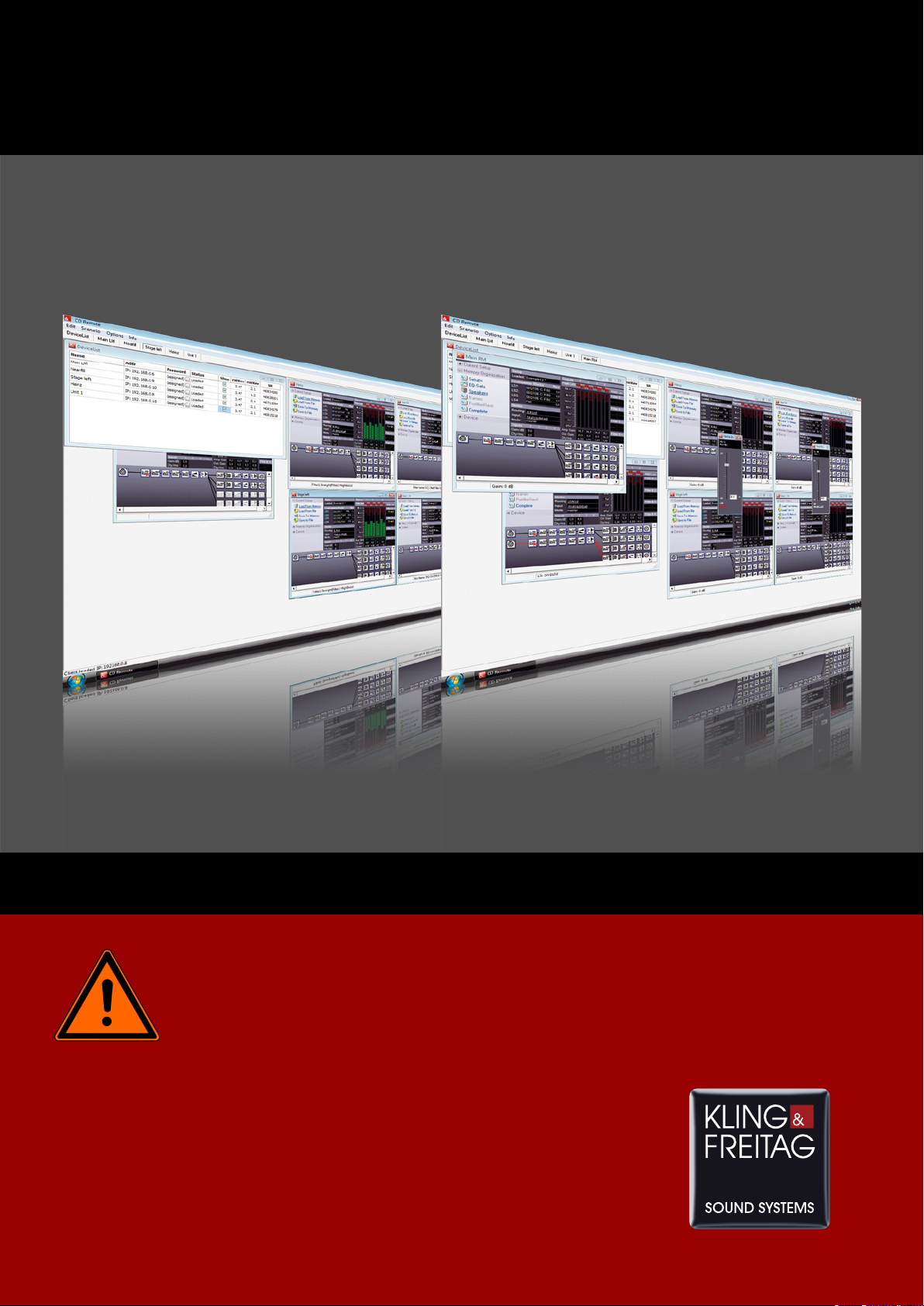
2.3 Overview of the software windows
The most important windows in the software interface are the “Main Window” where the
software runs, the “Login Window,” and the “Device Window”. If several controllers are
logged on, then the corresponding number of device windows may be open. Via the device
window, the respective sub-window can be opened for the relevant controller’s settings. In
the software, the main window is labelled with 'CD Remote', and the login window with
'DeviceList'. Each device window shows the name of the controller in the top frame.
KLING & FREITAG GMBH © 2014 Version 5.5 Page 8 of 50
Page 9
User's manual K&F CD 44 Remote
Main Window:
Login Window:
Device Window:
3. Scope of Delivery
The latest version of the remote software for operating the controller can be downloaded
from the Kling & Freitag website (www.kling-freitag.de). In addition to the remote software,
this package also contains the user's manual as a PDF file and software for updating the
firmware (Flashloader), including up-to-date firmware as well as the data for the current K&F
speakers (Speakers / LSBlocks).
KLING & FREITAG GMBH © 2014 Version 5.5 Page 9 of 50
Page 10

User's manual K&F CD 44 Remote
4. Product Description
With the software, you can carry through and administrate all settings on the CD 44, i.e.:
Organizing setups on the hard drive and loading to/from controller
You can load and edit the current settings from the controller’s memory (from Memory) and
save them onto your PC (to File) or in the controller (to Memory).
Creating and saving scenarios
You can save all settings of all opened Controllers – including the setups, links and the
graphic EQ-settings – onto the PC as Scenarios.
Linking several controllers (Master – Slave)
You can link multiple controllers with the software, enabling you to adjust the settings for
several controllers simultaneously.
Backup
You can create a backup copy of all settings with the [Complete] function.
Settings
• Password Administration
• Modes of Operation
You can find a description of the individual settings in the respective sections of the hardware
manual.
5. Requirements
5.1 Personal Knowledge
To operate the controller using the remote software, you should have basic working
knowledge of Microsoft Windows and be familiar with operating the K&F CD 44 Controller.
For this, see the corresponding user's manuals.
5.2 System Requirements
Hardware:
CD 44: a PC with Ethernet 10/100Base-TX network connection; firmware version 3.46 or
higher.
Software:
The software was tested with Microsoft Windows XP and Windows 7.
Operating systems other than Microsoft Windows are not supported!
You can download the relevant current remote software from the download area of the
Kling & Freitag website (www.kling-freitag.de).
The CD 24 controller can not be accessed with software version greater than V1.2.876. If you
need this version, please download it from our website To access the CD 44 controller you
should use the latest version of the CD 44 Remote.
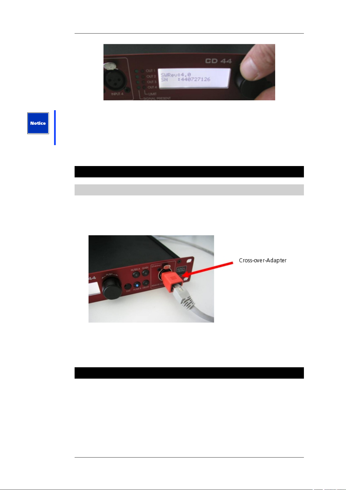
5.3 Requirements for the CD 44
Connect the controller to the mains voltage and determine the revision number in the
controller. To do so, open the following menus in the controller:
1. Click Util » Info, FWRev or click on SWRev.
KLING & FREITAG GMBH © 2014 Version 5.5 Page 10 of 50
Page 11
User's manual K&F CD 44 Remote
It's always recommended to use the latest firmware to ensure optimum performance. You
can find the latest software versions on www.kling-freitag.de With a firmware revision
number less than 3.4, you must also replace the IP Card built into the controller. To do this,
follow the steps as described in Chapter "Replacing the IP Card and Updating the Firmware"
on page 46. On older controllers, SWRev appears on the display instead of FWRev.
You can request an updated IP card in exchange for the old card from K&F.
6. Connection to the Computer
6.1 Connection of the CD 44
To connect the CD 44 to your computer, you have to use an Ethernet network cable and a
switching hub.
Alternately, you can connect the CD 44 directly (without a switching hub) to your computer.
In this case, you need a cross-linked Ethernet cable or a crossover adapter.
Some network interface cards automatically recognise the transmission and reception wires
of the connected controller and adapt to them. This function is referred to as Auto-MDI(X).
In this case, the type of cable used (cross-linked or normal) is irrelevant. To find out if your
network interface card is equipped with Auto-MDI(X), consult your network interface card’s
documentation.
7. Installation
To install the CD Remote Software, you need either the installation CD which accompanies
the device or the installation file "CD Remote Installer.exe", which you can download from
our website. Using this software, you install on your computer basic software with which
you can install an updated program version or repair or uninstall a version that is already
installed.
Current updated content of the software and the loudspeaker blocks are added during
installation over the required Internet connection. You therefore need an Internet connection
and additional administrator rights on your computer.
KLING & FREITAG GMBH © 2014 Version 5.5 Page 11 of 50
Page 12
User's manual K&F CD 44 Remote
7.1 Offline Installer
In addition to these usual installation options, we have also created for you the option of
generating an "Offline Installer". The "Offline Installer" is a file and folder structure with
fully updated software content and loudspeaker blocks, with which you need no Internet
access for a complete software installation.
The software of the corresponding computer, however, must be updated from time to time.
To do this, you can use an Internet connection, as usual, or also another Offline Installer. We
recommend that you create an up-to-date "Offline Installer" again shortly beforehand; this
would be updated over the Internet upon its creation and you could use it to update the
Remote Software CD of the computer in question.
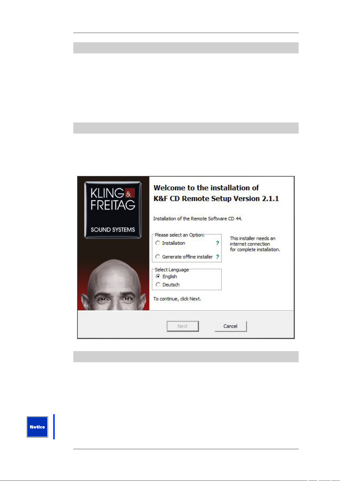
7.2 Procedure
When starting the software fo the first time, you can define the installation language and
choose between two procedures:
• Installation
• Create Offline Installer
7.3 Online and offlineinstallation of the Software
1. Use the accompanying installation CD or download the installation file from the
download area of our website (www.kling-freitag.de).
2. Copy the file CD Remote Installer Vx-xx.zip onto your PC.
3. Unzip the file and start the installation with a double click on the file [...].
4. Start the installation by double-clicking on the file CD 44 Remote Installer VX-XX.exe.
Please note that you need Internet access for both options so that the update content can be
added to the relevant installation.
KLING & FREITAG GMBH © 2014 Version 5.5 Page 12 of 50
Page 13
User's manual K&F CD 44 Remote
You can now choose between immediate installation on the current computer or the creation
of the offline data structure.
If you would like to create the offline installation files, follow the instructions under 'Creating
offline installation files'.
7.3.1 Installing the software on the current computer:
To carry out the installation on the current computer, please follow these instructions:
1. Select the option "Installation"
2. Select your preferred language.
3. Confirm your options with "Next".
4. Follow the installation instructions on the PC monitor.
5. Wait until all update content is added to the Offline Installer.
You can now use the software.
7.3.2 Creating offline installation files
To create the offline installation files, please follow these instructions:
1. Select the option 'Create Offline Installer'.
2. Select your preferred language.
3. Confirm your options with "Next".
4. Follow the installation instructions on the PC monitor.
5. Wait until all update content is added to the Offline Installer.
You have now created a program and folder structure so that you can install this program
version on another computer via a data carrier without needing an Internet connection.
For error-free running of the installation program, the file and folder structure must remain
unchanged.
1. Please copy the complete and unchanged folder structure to a CD or USB flash drive.
2. Place the data carrier in the CD drive of your computer or insert the USB flash drive in an
available USB port of the computer on which you want to install the software.
3. Run the file 'CD Remote Installer.exe" on the computer.
Since all necessary files and update content are stored in this installation, you can now install
an updated program version, together with the LS blocks that were up-to-date at the time of
creation, without an Internet connection.
Please note that the software and loudspeaker blocks on all of your devices should be
updated from time to time. The current Offline Installer is, of course, only updated with the
content that was relevant at the time of its creation. Content that is updated by K&F later on
is, of course, not included in the installation package created by you.
If you would like to run the software at a much later point in time, we recommend that
you create a new installation package just before an offline update so that current update
content is also installed.
7.4 Setting Up the IP Addresses
The following settings are only applicable to the CD 44 controller!
KLING & FREITAG GMBH © 2014 Version 5.5 Page 13 of 50
Page 14
User's manual K&F CD 44 Remote
7.4.1 Setting IP Addresses for the PC
1. On the Windows desktop, go to [Start] » [Settings] » [Control Panel] » [Network
Connections] » [LAN Connection] (double click) » [Properties] » [Internet Protocol (TCP/IP)]
» [Properties] » [Use the following IP address]
2. Set a fixed IP address (i.e. 192.168.0.100).
The first three digit fields of the computer’s and controller’s IP addresses must be
identical. The last digit field must be different, ranging between 1 and 254. If you
connect several controllers, then each one must have a different final digit field or the
communication will fail. Please do not change the subnet mask address 255.255.255.0
without a special reason.
The controller’s IP address that is set at delivery is 192.168.0.15.
192.168.xxx.xxx is reserved for private networks and is therefore recommended.
3. Click OK twice to save the changes.
If your system requires dynamic IP addresses, go to 'Alternative Configuration' and enter
the desired address for the controller at User-Defined. This way you can use a static IP
address in a network environment with dynamic addresses. In any case, the controller
itself requires a static IP address.
Tip
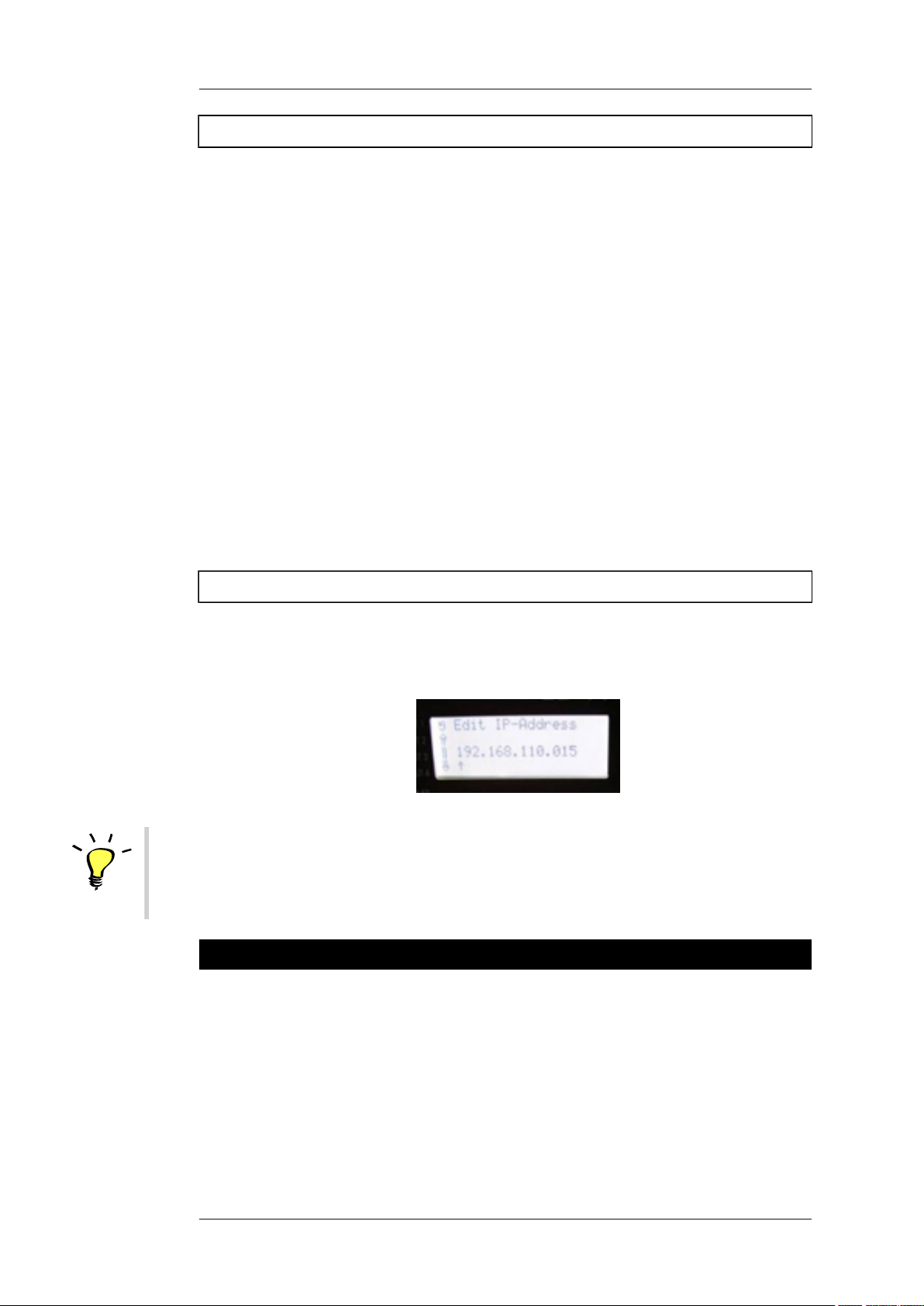
7.4.2 Setting the IP Address on the CD 44
As an alternative to the steps described above, you can change the IP address of the
controller to match that of your computer. In this case, the first three fields of the IP address
have to match.
1. Click on Util » IP-Address.
The new IP address is valid after the controller has been restarted!
8. Passwords and Access Rights
The controller differentiates between three different authorization modes which called
Master, User, and Lock Mode.
You can find information about changing the passwords and the different modes in
“Changing General Settings (Device)” on page 22.
Administrator Password: The administrator password depends on the serial number and
cannot be changed. It is provided with a sticker on delivery and is required to change the
master and user passwords. If you forget the master password, you can use the administrator
password instead.
Master and User Passwords: The default password for the master mode is 'master', and for
user mode 'user'. Please note the lower case spelling.
KLING & FREITAG GMBH © 2014 Version 5.5 Page 14 of 50
Page 15

User's manual K&F CD 44 Remote
We recommend that the owner of the controller changes the user and master passwords
before others use it. This ensures that no settings are made by unauthorised persons, which
could result in the malfunction or damage of speakers.
Passwords will be reset to the default passwords after updating the software.
The three different access modes:
Master:
In the master mode, the full range of operations is possible. To access this mode, you need
either the master or the administrator password.
User:
Users only have access to a limited range of operations (they cannot change setups or LS
blocks, etc.). This mode is appropriate when you lend out the controller, for example, and you
do not want the user to make any fundamental changes or adjustments that could possibly
endanger the operating safety. The corresponding functions are grey and thus not selectable
in the software. To access this mode, you need the user password.
Lock all: No adjustments of any kind can be made on the controller. This mode protects the
controller from unauthorized access. If a controller is started with an incorrect password or no
password whatsoever, then it starts in the Lock all mode.
There is also a differentiation between the device mode and the software mode.
The Device mode defines the operating rights in the controller when it is not being operated
with the remote software.
The Software Mode defines the operating rights in the remote software, irrespective of the
device mode. The appropriate mode is selected by entering the password when logging in.
The device window is started in the software mode that corresponds to the password entered
at login. If no password or an incorrect password is entered, it is started in the Lock all mode.
See Chapter Calling the Controller in the Software on page 16. If the controller is logged
off, it returns to its original device mode.
The passwords for the device mode and the software mode are identical.
If a controller is logged into the remote software, then operations on the controller itself are
blocked.
9. Starting the Software and Logging On the Controller
9.1 Starting the Software
1. Click on Start » All Programs » Kling & Freitag CD 44 Remote » CD Remote.
9.2 Logging On the Controller
9.2.1 Selecting the IP Address of the PC in the Software
CD 44 only!
You must select the IP address directly in the remote software. In case there are several
network participants with separate IP addresses (i.e. several network adapters), you must
select the adapter that you would like to use.
1. Click on Edit » Connection Settings.
2. In the area IP SettingsActivate the control box Enabled.
3. Your PC’s IP address is shown. If several IP addresses are assigned or several network
interface cards are installed, select the appropriate IP address.
KLING & FREITAG GMBH © 2014 Version 5.5 Page 15 of 50
Page 16

User's manual K&F CD 44 Remote
4. If your network does not recognise the controller, it is possible that it did not have
enough time to scan all network addresses. In this case, increase the time for the Network
Polling (a value that is too high slows its locating your controller). The maximum value is
200 ms.
9.3 Calling the Controller in the Software
When the software has been started, it automatically looks for controllers in the network.
Connected CD 44 are only recognised, though, when the first three digit fields of all
controllers’ IP addresses are identical and each last field has a different value.
After a few seconds, all of the connected controllers should be shown.
1.
Click in the column 'Password' on .
Enter the password of the access mode that you want to login to. If the software has
been started with an incorrect password or no password whatsoever, then it starts in the
Lock all mode.
The PC saves each last-used password and uses it for the next login attempt.
To delete the password from the entry mask, take the following steps:
2. In the main window, click on Edit » Clear Stored Passwords.
Upon delivery, the name of the controller is “Unit 1”. If you want to work with several
controllers online, you must give the controllers different names. See Chapter Changing
the Controller Name (Name) on page 23.
KLING & FREITAG GMBH © 2014 Version 5.5 Page 16 of 50
Page 17

Tip
User's manual K&F CD 44 Remote
3. Activate the control box Online.
The device window is opened and the controller is online.
The controller’s IP address and “Remote Controlled” are shown on its display, thus
making manual operation on the controller itself no longer possible.
Devices with extended memory are highlighted in the DeviceList Window.
10. Menus in the Main and Login Windows
10.1 Short Description of Main Window Menus
Name Submenu Function
Connection Settings Connection SettingsEdit
Clear Stored Passwords Clears all passwords stored
in the PC
Scenario
Options Global Settings Global settings for Anti-
Info Software version
Load from File Load scenario from PC
Save to File Save scenario on PC
Link Manager Link function blocks of
one or several controllers.
See Chapter Link
manager, links of function
blocks on page 35.
Air-Loss filter and for
activation and storage
directory of the Complete
Defaults for offline
devices.
information
Name Function
DeviceList Brings the login window to the front
KLING & FREITAG GMBH © 2014 Version 5.5 Page 17 of 50
Page 18

User's manual K&F CD 44 Remote
Unit 1, Unit 2, [device name] Device window of the corresponding
controller is brought to the front
10.1.1 Global settings
Change global settigns at: Click on Options » Global Settings.
Setting Function
Device window To save space on the screen, clear the
check box. The channel name will be
hidden in the device window.
Delay/Units Choose the delays in meters or
milliseconds
velocity Acoustic velocity
air attributes H: Relative humidity
T: Air temperature
Offline Devices Activate the checkbox if Offline Devices
(virtual devices) should have complete
preset data and settings.
In the menu, enter which setting file
should be loaded after creating a virtual
controller.
The checkbox is activated by default and
the CDX4 Complete Defaults VX-XX.dcc
provided upon delivery is loaded.
To create your own Complete Defaults,
follow these steps: In the device window,
click on Memory Organization » Complete
» SaveToFile.
Refer to chapter Working with Virtual
Controllers (Offline Devices) on page
40.
10.2 Menus of the Login Window (DeviceList)
Name Function
Name Name of the CD 24 / CD 44 CD 44
Interface IP address of the CD 44
Password Password (“assigned” indicates that a
password for the controller has been
saved on the PC)
KLING & FREITAG GMBH © 2014 Version 5.5 Page 18 of 50
Page 19

User's manual K&F CD 44 Remote
Status Found: Controller recognised
Loaded: Controller signed on and setup
loaded
Closed: Controller signed off.
Online 2)
Offline 2)
FWRev Firmware version
HWRev Hardware version (circuit boards)
SN Controller’s serial number
2) Devices with extended memory are highlighted in the DeviceList Window.
This checkbox is only available for
controllers that are connected with the
computer.
If this checkbox is activated, the device
window opens and the controller can
be operated using the software. It is
no longer visible for other users in the
network.
This checkbox is only available for virtual
controllers.
If this checkbox is activated, the device
window opens and the virtual controller
can be operated using the software.
Refer to chapter Working with Virtual
Controllers (Offline Devices) on page
40.
11. Changing / Saving Device Settings
Changed settings are saved onto the controller in intervals of approx. five seconds so that any
changes to the settings are saved in the case of a loss of power, for example. If you switch off
the controller, these settings remain active. The changes made to the setups, however, are
not saved automatically. You must manually save them after finishing the settings. Refer to
chapter Load and Save Current Setups (Current Setup) on page 21.
11.1 General Procedure for the System Setup
If you want to set up a system configuration, start by mapping the wired hardware in the
software and adjust the setup details afterwards.
Proceed as follows:
1. Select the desired routing.
2. Select the desired input patching.
3. Select the connected speakers.
4. Enter a name for the signal output.
5. Adjust the individual filters, limiters, etc.
6. Create the desired master operating elements.
7. For setups with several controllers, you can save the complete configuration as a scenario.
You can find a detailed description of the system configuration in the hardware manual.
KLING & FREITAG GMBH © 2014 Version 5.5 Page 19 of 50
Page 20

User's manual K&F CD 44 Remote
To assign a name to a signal output, double-click the default name above the toolbar or click
on the [Output].
Menus in the Device Window
KLING & FREITAG GMBH © 2014 Version 5.5 Page 20 of 50
Page 21

User's manual K&F CD 44 Remote
11.1.1 Brief Description of the Menus in the Device Window
Name Submenu Function
Current Setup
Memory Organization
Load/Save active Setups
from/to PC/controller
Load from Memory Load setup from
controller
Load from File Load setup from PC
Save to Memory Save setup on controller
Save to File Save setup on PC
Load or save without the
setups in the controller
being changed. (In
complete backup, even
the current setups will be
overwritten)
Setups Organizing Setups
EQ-Sets Organize equalizer presets
Speakers Organize speaker sets
(LSBlocks)
Names Function not available for
user
PrefilterRest Function not available for
user
Complete Load or save a backup
copy of all controller data
(Complete Backup)
Device
Name Change device names
Passwords Change passwords
DeviceMode Change access rights /
You can find detailed descriptions of the submenus in the following chapters.
Organize general settings
access mode
11.2 Load and Save Current Setups (Current Setup)
In the menu 'Current Setup', you can load the setups from the controller’s memory or from
the PC into the random access memory of the controller.
By default, the CD 44 is delivered with fourteen (Example 1 - 14) exemplary setups. You can
change the corresponding setups and save them under another name as new setups.
KLING & FREITAG GMBH © 2014 Version 5.5 Page 21 of 50
Page 22

User's manual K&F CD 44 Remote
A total of up to 64 setups can be saved in the controller. The file name extension '.dsc' is
automatically assigned when you save a setup on the PC.
If you make changes in the 'Current Setup', an asterisk (*) appears under 'Setup Loaded:
[Setupname]'.
This applies for setups with the same name too! If a setup is loaded from a file with Current
Setup » LoadFromFile or from a scenario, the current setup will be overwritten.
Load From Memory
Loading setups from the controller´s memory: In the device window, click on Load From
Memory » Selecting a file » OK.
Load From File
Loading setups from the PC: With [Load From File] » [Open], you can open the setups that
are saved in the computer. In the device window, click on Load From File » Selecting a file »
Open. The files are saved in .dsc format (Example 1.dsc, etc.). If you want to keep your Setup
in the controller, even after switching off the CD 44, you have to store your Setup with Save
To Memory.
Save To Memory
Saving the current setup in the controller: In the device window, click on Save To Memory »
Select a name or click on new » OK.
Save to File
Saving the current setup on the PC: In the device window, click on Save to File » Select a path
and Select a name » Save.
Tip
The name of the setup is kept, independant of chosen file name. If you want to rename the
setup in the device window (Setup Loaded:), then you must do so by first saving it in the
device.
In the device window, click on Save To Memory » Select a name or click on new » OK.
11.3 Changing General Settings (Device)
In this menu, you can change device names, passwords, and access rights.
KLING & FREITAG GMBH © 2014 Version 5.5 Page 22 of 50
Page 23

User's manual K&F CD 44 Remote
11.3.1 Changing the Controller Name (Name)
If you use several controllers in a network, it is essential that the controllers have different
names. Otherwise, the controllers cannot be addressed in the network. You can choose any
name you wish.
You can change the name as follows:
1. Open the device window.
2. Click on Device » Name.
3. Enter the new name.
4. Click on OK.
11.3.2 Changing Passwords (Passwords)
You can change the passwords as follows:
1. Open the device window.
2. In the device window, click on Device » Passwords.
3. Enter the administrator password.
4. Select the password that you want to change.
5. Enter the new password.
11.3.3 Changing the User Group (Device Mode)
With this function, you can choose which permission mode is effective if the device is not
controlled using the software. The current mode is shown in the middle area of the device
window under 'Mode:'.
You can set the mode as follows:
1. In the device window, click on Device » DeviceMode. Select the desired mode.
KLING & FREITAG GMBH © 2014 Version 5.5 Page 23 of 50
Page 24

Tip
User's manual K&F CD 44 Remote
If the chosen mode is lower than the original (i.e. from master to user), then no password
is requested. If the chosen mode is higher than the original (i.e. from lock all to user),
then the password of the newly selected mode is requested.
2. Enter the appropriate password.
11.3.4 Device Info
Besides the serial number and software revision you will find here some additional
information in case of service is required.
11.4 Organizing the Controller’s Memory (Memory Organization)
You can save data from the controller to the hard drive of the PC, transfer data from the PC
to the memory storage of the controller, and delete data in the controller. These functions
make sense if, for example, you want to transfer data sets from one controller to another, or
if you want to remove non-used LS blocks from the controller in order to make the context
menu for the speakers more concise.
If you move your cursor in Memory Organization over Setups, EQ-Sets or Speakers, you will
get a quickinfo how much memory is in use and how much memory your device has at all.
11.4.1 Organizing Setups
Under Memory Organization » Setups in the device window, you can organize the Setups in
the controller.
1. Add
With Add, you can load the Setups from the PC to the memory of the controller. A file
selection window opens where you can select the desired file with the extension *.dsc.
Then this Setup is available at Current Setup » Load From Memory and can be loaded as
the current setup, if desired.
2. SaveToFile
KLING & FREITAG GMBH © 2014 Version 5.5 Page 24 of 50
Page 25

User's manual K&F CD 44 Remote
With SaveToFile, you can save existing Setups from the controller to the PC. Multiple
selections are possible. A file selection window opens where you select the path and
name to save it as.
3. Delete
With Delete you can delete Setups from the controller´s memory. Multiple selections are
possible.
The preset file path for the Setups is:
My Documents or Shared Documents\Kling & Freitag\CD Remote\CDX4 Setups\*.dsc
11.4.2 Organizing Equalizer Presets (EQ-Sets)
CD 44 only!
Under Memory Organization » EQ-Sets in the device window, you can organize existing EQ
settings of the 31 third band EQ.
1. Add
With Add, you can load the EQ-Sets from the PC to the memory of the controller. A file
selection window opens where you can select the desired file with the extension *.dec.
Then this EQ set is available in the controller. To use the EQ-Set, double click on the
following symbol of the corresponding channel:
When you then click the button Load, a file select window opens where you can select
the desired EQ-Set (*.dec).
2. SaveToFile
With SaveToFile, you can save existing EQ-Sets from the controller to the PC. Multiple
selections are possible. A file selection window opens where you select the path and
name to save it as.
3. Delete
With Delete you can delete EQ-Sets from the controller´s memory. Multiple selections are
possible.
11.4.3 Organizing Speakers (LSBlocks)
At Speakers » LSBlocks in the Device Window, you can organize 64 LSBlocks (device without
extended memory) or 192 LSBlocks (CD 44 device with extended memory).
You can use the controller and the software for Kling & Freitag speakers only. The necessary
parameters such as limiters and filters, etc. are preset for the respective speakers. The
individual settings for the different speakers cannot be changed.
1. Add
With Add, you can load the Speakers from the PC to the memory of the controller. A file
selection window opens where you can select the desired file with the extension *.dbc.
Then this speaker is available in the controller. To use the speaker in the controller, select
the following symbol of the corresponding channel:
A selection window opens where you can select the desired speaker.
2. SaveToFile
With SaveToFile, you can save existing Speakers (LSBlocks) from the controller to the PC.
Multiple selections are possible. A file selection window opens where you select the path
and name to save it as.
KLING & FREITAG GMBH © 2014 Version 5.5 Page 25 of 50
Page 26

User's manual K&F CD 44 Remote
3. Delete
With Delete you can delete Speakers (LSBlocks) from the controller´s memory. Multiple
selections are possible.
If the Speaker (LSBlock) is used in setups, a warning prompt appears that you must
confirm by clicking [OK].
In this case, you must first delete the setups in which the Speaker (LSBlock) is used. Then
repeat the procedure and confirm the deletion or cancel the procedure.
You can download the latest relevant Speakers (LSBlocks) from the download area of the
Kling&Freitag website (www.kling-freitag.de)
The preset file path for the Speakers (LSBlocks) is:
My Documents or Shared Documents\Kling & Freitag\CD Remote\LS-Blocks\
Save the (unzipped) files with the Speakers (LSBlocks) at the default location in order to
use them.
11.4.4 Complete Backup
With this function, you can create a backup of all data and settings of the controller (setups +
EQ sets, speaker sets (LSBlocks), IP addresses, display settings, etc.).
1. SaveToFile
You can save the controller’s settings as a file on the PC.
Click on Memory Organization » Complete » SaveToFile.
Enter the desired file names. The file is then saved with the extension .dcc.
The default file location for the settings file is: My Documents or Shared Documents\Kling
& Freitag\CD Remote\
2. LoadFromFile
Click on Memory Organization » Complete » LoadFromFile.
Select the backup file.
Please note that all settings stored in the controller will be lost.
You will be promted if you want to keep the Ethernet address and the name of the
controller or if you want to load it from the file. Additionally, you can replace the actual
passwords with the ones of your backup file. Please note, that you can change the actual
passwords only with the Administrator Password. Select the desired option.
You can download the latest relevant CDX4 Complete Defaults VX-XX.dcc (these are the
controller settings present at the delivery status) from the download area of the Kling &
Freitag website (www.kling-freitag.de).
KLING & FREITAG GMBH © 2014 Version 5.5 Page 26 of 50
Page 27

Tip
Tip
User's manual K&F CD 44 Remote
You can load a 'Complete Backup' of a CD 44 without extended memory into a one with
extended memory. All not used memory will be overrided by dummy data. To save data the
oppsite direction is not possible.
Important information for users of SEQUENZA 10 N/W
Only applies when updating the CD 44 Remote Software from a version lower than 1.3 to a
version 1.3 or higher!
After loading a complete backup, the controllers still do not contain the current SEQUENZA
10 N/W Speakers (LS Blocks), which provide the full ease of use. With the current ones the
SEQ LShelv Filter will be adjusted just by clicking the number of used loudspeakers. See
Chapter Parametric Filters on page 32.
To get this feature working you have to update the SEQUENZA Speakers (LS Blocks).
An update for enhancing the ease of use is necessary only if the revision of the SEQ Speakers
(LSBlocks) is lower than 1.4.
You will find the revision number of your Speakers (LSBlocks) in the device Window in the
[Rev] column.
Without updating your SEQUENZA Speakers, you have to adjust the SEQ LShelv Filters for the
SEQUENZA 10 N/W manually. See the corresponding table in chapter [Parametric Filters 'PEQ'
+ SEQ LShelv (Filter A Taste)] in the controllers' hardware manual.
KLING & FREITAG GMBH © 2014 Version 5.5 Page 27 of 50
Page 28

User's manual K&F CD 44 Remote
12. Input Patching (Input Configuration)
CD 44 only!
With the input patching, you can configure the physical inputs. This way, you can, for
example, correct physically flipped inputs in the controller without having to change the
actual connectors, you can select if you want to connect a digital or analogue signal to the
inputs or you can create a mono-sum of the inputs 1 and 2.
12.1 Available input patchings
By default, the following patchings are available.
Input Patching Function
Analog.default Standard, analog
Analog.Flipped 1 and 2, or 3 and 4 flipped, analog
Analog.1+2 Mixed Mono-sum of 1 and 2, analog
Digital.default Standard, digital
Digital.Flipped 1 and 2, or 3 and 4 flipped, digital
Digital.1+2 Mixed Mono-sum of 1 and 2, digital
You will find a detailed description of the individual patchings in the hardware manual.
12.2 Selecting Patchings
You can select the patchings available in the controller as follows:
1. In the device window, click the current patching (Modes: Input:).
2. Select the desired patching.
KLING & FREITAG GMBH © 2014 Version 5.5 Page 28 of 50
Page 29

User's manual K&F CD 44 Remote
13. Routings
The routings determine how one or several input signals can be switched to the outputs and
which path these signals will take. You can find detailed descriptions of examples with the
corresponding circuitry and connection diagrams in the hardware manual.
13.1 Available routings
By default, the following routings are available.
• 1 in 4 out
• 1 in 4 out (Linked)
• 2 in 4 out
• 2 in 4 out (Linked)
• 4 in 4 out
• 1 in 2 + 2 in 2
• 1 in 3 + AUX
• 1 in 4 in 4
• 1 in 3 + 1 in 1
• 2 in 4 in 4
• 1 in 2 + Aux + 1 in 1
• 1 in 2 in 2 + 2 in 2
13.2 Selecting Routings
You can select the routings available in the controller as follows:
1. In the device window, click on the current Routing.
2. Select the desired routing.
The signal path of the selected routing is depicted in the lower part of the device window.
KLING & FREITAG GMBH © 2014 Version 5.5 Page 29 of 50
Page 30

User's manual K&F CD 44 Remote
14. Setting Filters, Limiters and Delays
You can change the individual settings for filters, the connected speakers for every channel,
delays, limiters, etc. after having selected the corresponding routing and input patching for
the current system configuration. The relevant icons appear in the lower area of the device
window.
14.1 Overview of the Symbols
Icon Function (shown on mouseover)
31 band 1/3rd octave EQ (see EQ 31 Band
in the hardware manual) (CD 44 only)
Filters (see Parametric Filters and High
Boost, Cluster, and Bass Boost Filter on in
the hardware manual.)
Connected speakers (see Select LSBlock in
the hardware manual.)
Limiter (see LimReduction in the
hardware manual.)
Input and Output Gains (see chapter
Gains in the hardware manual.)
Delay (see chapter Delay in the hardware
manual.) (The input delay is only available
for the CD 44.)
Outputname
Amp Gain (see AmpGain in the hardware
manual.)
14.2 Changing Parameters
Follow the instructions for the individual settings in the hardware manual. You can change
the setting as follows:
1. Double click the relevant [Icon].
2. Set the desired value.
3. Push the enter button on the PC keyboard if you have entered the values on the
keyboard so that the setting will be run.
You can also make all entries using the arrow buttons or the scroll wheel of the mouse. You
can also simultaneously hold down the [Ctrl] button to increase and [Alt] to decrease the
increments.
KLING & FREITAG GMBH © 2014 Version 5.5 Page 30 of 50
Page 31

User's manual K&F CD 44 Remote
The changes do not have to be saved separately on the controller, as they are immediately
transferred to the controller and are saved after 5 seconds at the latest. If the main supply
should be diconnected, the changes won't get lost.
14.2.1 Equalizer (WYSIWYG)
14.2.1.1 Operation
As of firmware version 5.1 there is an additional WYSIWYG mode for the Graphic EQ. In a
traditional 31 band EQ, the value of a frequency band also influences its adjacent bands. For
this reason, the real generated frequency response differs from that which is actually set.
The influence of the bands and the resulting outcome can be clearly seen in the following
screen.
Using the WYSIWYG mode, the resulting frequency response now matches the set frequency
response.
If the controller is in WYSIWYG mode, the target frequency response is calculated internally
and then adjusted by the 31 Bell filter of the GEQ. The settings are updated after each GEQ
modification.
The mode is saved in the controller's EQ setting and can be changed both in the remote
software and on the device. You can switch the mode on and off in the Edit EQ window.
14.2.1.2 Setup change and filter changes
Until now, a mute function was run when loading set-ups or LS blocks. In contrast, a fade
function is run on the basis of coefficients when changing single filters.
KLING & FREITAG GMBH © 2014 Version 5.5 Page 31 of 50
Page 32

Tip
20
50
10
0
50
0 1
000
50
00
10000
20000
-1
2
-1
0
0
+3
15
14
Frequenc
y i
n [H
z]
Amplitude
i
n
[
d
B]
FilterType = 'LShelv'(ShelvingLowpass)
Gain= +3d
B
Freq = 1000Hz
Q = 0.707 (def
ault)
Q =
10
User's manual K&F CD 44 Remote
This procedure was modified in the new firmware. The fade function is no longer run on
the basis of coefficients, but on the basis of the analogue filter settings. Therefore, a mute
function is no longer necessary when loading set-ups and LS blocks.
This raises the possibility of a better A/B comparison between two loudspeaker blocks.
Furthermore, instead of using a filter which can be switched in one LS block, two LS blocks
can be saved, one with and one without a filter. The switching functions are then accessed by
loading the blocks.
14.2.2 Parametric Filters
You will find a detailed description of the filters in the hardware manual.
LShelv (Low Shelving Filter) and HShelv (High Shelving Filter)
A Q higher than 0.707 is not applicable for LShelv and HShelv and may result in undesired
changes in the sound (see graph). Q can be adjusted in steps of 0.001 ranging from 0.2 to 20.
SEQ LShelv
Only with the current SEQUENZA 10 N/W Speakers (LSBlocks) you can adjust the LShelv Filters
for Sequenza tops by clicking the number of used loudspeakers.
To do so, click a symbol for the filters in the Device Window and, next to the entry Named
Filter, click the number of SEQ shown there. In the drop-down menu, select the number of
Sequenza Tops that you will use in the corresponding array. The sound engineer can fine tune
the values on the controller as soon as the controller is no longer connected to the computer.
KLING & FREITAG GMBH © 2014 Version 5.5 Page 32 of 50
Page 33

Tip
20
50
10
0
50
0 1
000
50
00
10000
20000
-2
4
-1
2
-3
0
10
20
Frequenc
y i
n [H
z]
Amplitude
i
n
[
d
B]
FilterType =
'HighP
' (High
pas
s)
Freq = 1000H
z
Q= 0.707 (default)
Butterworth -12dB/Oct
Q =10
User's manual K&F CD 44 Remote
If it's not possible to change the filters by clicking the number of speakers, you are not using
current SEQUENZA 10 N/W Speakers (LSBlocks).
In this case you can update the corresponding Speakers (Ls Blocks). See Important
information for users of SEQUENZA 10 N/W in Chapter Updating the CD Remote Software on
Page 44 f.
Without updating your SEQUENZA Speakers, you have to adjust the SEQ LShelv Filters for the
SEQUENZA 10 N/W manually. See the corresponding table in chapter [Parametric Filters 'PEQ'
+ SEQ LShelv (Filter A Taste)] in the controllers' hardware manual.
HighP (High Pass Filter) and LowP (Low Pass Filter)
A Q higher than 1 causes a level increase of the crossover frequency.
In order to prevent an unintended level increase, the filter level is set at 0.7 by default when
switching the filters. A Q of 0 results in a high or low pass of the 1st order, that is 6 dB/octave.
14.2.3 Anti Air-loss Filter
With this filter, you can compensate the high range losses over longer transmission ranges.
The dissipation can be compensated using the first filter of the PreEQ’s in the form of a bell
filter.
You can change the setting as follows:
1. In the relevant filter, click the box next to 'Anti Air-Loss'.
2. Enter the desired distance in metres.
As with the temperature and humidity settings under [Options] » [GlobalSettings], the filter is
set and can no longer be manually changed. By entering the distance of “0”, the filter will be
manually operable again with the last used values.
For setting the temperature and humidity See Chapter Global settings on page 18.
Description:
Changing the temperature or humidity in the GlobalSettings-Dialogue leads to an immediate
update of the activated anti-dissipation filter while taking each distance setting into
consideration.
Using the given parameters, the software calculates a compensation filter which is optimally
adapted to the air absorption curve.
KLING & FREITAG GMBH © 2014 Version 5.5 Page 33 of 50
Page 34

User's manual K&F CD 44 Remote
0
2
4
6
8
10
12
14
1
00
1000
100
00
10
0000
Diss
Filte
r
0
2
4
6
8
10
12
14
1
00
1000
10000
100000
Diss
Fi
lte
r
0
2
4
6
8
10
12
14
10
0
10
00
1
000
0
1
000
00
Dis
s
Filter
The compensation range is meticulously limited by the software so that no technically
meaningless extreme corrections can take place. This way the maximum level increase is
restricted to 10 dB, just like the filter middle frequency is restricted to values between 6 kHz
and 20 kHz.
If such a calculated target curve results in a theoretical compensation increase above 10 dB,
the maximum compensation frequency will be re-calculated.
Examples:
Parameters: 22°, 70%, 30m
-3dB compensation point: 21000 Hz, maximum compensation deviation: 0.24dB
Parameters: 22°, 70%, 50m
-3dB compensation point: 15924 Hz, maximum compensation deviation: 0.273dB
Parameters: 22°, 70%, 100m
-3 dB compensation point: 10900 Hz, maximum compensation deviation: 0.45 dB
KLING & FREITAG GMBH © 2014 Version 5.5 Page 34 of 50
Page 35

User's manual K&F CD 44 Remote
0
2
4
6
8
10
12
14
10
0
100
0 1
000
0
1
0000
0
Diss
Filte
r
0
2
4
6
8
10
12
14
1
00
10
00
100
00
100000
Diss
Filter
0
2
4
6
8
10
12
14
1
00
1000
10000
100000
Dis
s
Fi
lte
r
Parameters: 4°, 40%, 120m
-3 dB compensation point: 4973 Hz, maximum compensation deviation: 0.24 dB
Parameters: -4°, 40%, 120m
-3dB compensation point: 8160 Hz, maximum compensation deviation: 0.34 dB
Parameters: -4°, 30%, 120m
-3 dB compensation point: 16068 Hz, maximum compensation deviation: 1.5
15. Link manager, links of function blocks
For easier operating, the individual function blocks can be linked and are thus placed into a
Master – Slave relationship. The operating element that takes over the controls is called the
Master, and the operating elements that are controlled by the Master are called Slaves.
Aside from connecting Function Blocks within one controller, Function Blocks can also link
between different devices.
The following can be linked:
1. Graphic Equalizers (CD 44 only)
2. Input Gains
3. Input Delay (CD 44 only)
4. Limit Reduction
5. Output Gain
KLING & FREITAG GMBH © 2014 Version 5.5 Page 35 of 50
Page 36

User's manual K&F CD 44 Remote
6. Output Delay
7. parametric equalizer
The links between Master and Slave are relative, meaning that if the Master and Slave have
different values when the links are set up, then this offset is maintained when the Master’s
value changes.
You can also change the Offset in the Slave later.
Example: The Gain Setting of the Master is 0 dB upon creating the link; the Slave is preset
with +2 dB.
If you increase the value of the Master to +4dB, the setting of the Slave also increases by
+4dB to +6dB. The Offset is, therefore, +2dB.
If you would now change the Gain Setting in the Slave to +7dB, the Offset would be +3dB in
the future.
The Offset is reset when you click on [Link] » [reset] in the Device Window of the Slave or
when you select [Scenario] » [Linkmanager] » [resync] in the window.
The Slaves thus assume the exact value of the Master.
A Master cannot become a Slave of any other element.
Links are only saved on the PC and will no longer be active in the controller as soon as it has
been logged off the software.
Note:
Wenn Sie in der Lautsprecher-Auswahl einen SEQUENZA-Lautsprecher gewählt haben,
werden im vierten Equalizer (EQ4) die Frequenz-, Qualitäts- und Gain-Werte für einen
Lowshelf-Filter aus dem entsprechenden LS-Block voreingestellt. Die Felder werden
ausgegraut und damit sind die Werte nicht mehr veränderbar.
Bei Sequenza-Lautsprechern wird das Lowshelf-Filter über die Anzahl der Lautsprecher
bestimmt.
15.1 Linking Function Blocks
You can link the function blocks as follows:
1. Click on Scenario » Link Manager.
In the dropdown list 'View', you can determine in which sort sequence the Function
Blocks shall be shown.
2. First select [add link] for the Function Block of a device that should be the Master. In the
following example, this is the EQ 1 of the device "Unit 1".
3. The window "SlaveDialogs" opens. Here you can select one or several Function Blocks
that are to follow the Master.
KLING & FREITAG GMBH © 2014 Version 5.5 Page 36 of 50
Page 37

User's manual K&F CD 44 Remote
15.2 Organizing and Deleting Links
In the Link Manager, you have the possibility to manage the links:
With the following, you can
[add link] – create a new link,
[show window] – show the corresponding Device Window,
[resync all slaves] – resync all linked devices to the setting of the Master (remove Offsets),
[remove link] – delete a link,
[resync slave] – resync the settings of a linked Function Block to the settings of the Master
(remove Offset)
The following example shows two linked equalizers. The equalizer of Unit 1 is the Master.
KLING & FREITAG GMBH © 2014 Version 5.5 Page 37 of 50
Page 38

User's manual K&F CD 44 Remote
In the device window under the entry Link, you can see if the Function Block is a Master or a
Slave. In the case of the device 'Unit 1 / EQ 1', it is a Master. If you click on the entry Master
(red), a window appears that will show you which devices and Function Blocks are set as
Slave.
In the case of the device 'Unit 2 / EQ 1', it is a Slave. Under the entry 'Link', you can see which
device and which Function Block is a Master.
If you click on this entry, then you can use Reset to overwrite the current parameters of the
Slave with those of the Master.
16. Scenarios
You can save all settings of all opened Controllers – including the setups, links and the
graphic EQ-settings – onto the PC as Scenarios.
This way, you can quickly re-open all settings of several controllers and opened windows in
the same position and size. This is advisable when you want to operate alternating system
configurations, for example. Scenarios are saved on the PC only.
If a setup is loaded from a file with Current Setup » LoadFromFile or from a scenario, the
current setup will be overwritten.
16.1 Loading Scenarios
1. In the main window, click on Scenario.
2. Click on LoadFromFile.
3. Select the relevant file.
After this, the settings of all controllers saved in the scenario are set, and all saved operating
elements are opened. If one or more controllers from the scenario are not found, then this
is shown in a window Missing Scenario Devices. You are asked if you want to automatically
create corresponding virtual devices.
KLING & FREITAG GMBH © 2014 Version 5.5 Page 38 of 50
Page 39

User's manual K&F CD 44 Remote
Click on Auto create Virtual Devices » Continue. Virtual Controllers with the names of the
missing controllers and the corresponding settings are automatically created this way.
The controllers saved in the scenario are identified by their name, not by their serial number
or IP address.
16.2 Saving scenario
1. In the login window, click on Scenario.
2. Click on SaveToFile.
3. Enter the desired file name and click on Save.
KLING & FREITAG GMBH © 2014 Version 5.5 Page 39 of 50
Page 40

User's manual K&F CD 44 Remote
17. Working with Virtual Controllers (Offline Devices)
The software enables you to edit settings on virtual devices and to transfer these settings
to existing controllers at a later time. This is useful if you are at a different location than
the controller, but you would like to edit the settings anyway. You can also use the Offline
Devices in order to get to know the software.
17.1 Creating Virtual Controllers
1. Start the software. Click on Start » All Programs » Kling & Freitag CD 44 Remote » CD
Remote.
2. Click on Offline Devices » Add.
3. Choose a name for the virtual controller. Click on OK. Please note that the name cannot
contain more than 15 characters.
4. You will be asked, if you like to create a virtual device with or without extended memory.
The virtual device must correspond to your real one.
5. Close the window Offline Devices when you do not want to add or remove any more
devices.
KLING & FREITAG GMBH © 2014 Version 5.5 Page 40 of 50
Page 41

User's manual K&F CD 44 Remote
6. Activate the control box Offline. The Device Window opens, and you can edit settings of
the virtual controller. As with an existing controller, you can also create, save and load all
settings.
Tip
If you create a virtual controller with the name of a real controller, then only one device
will appear for both controllers in the DeviceList. In this case, you can switch back and forth
between the devices by activating and deactivating the checkbox [Online] or [Offline].
Please note that from now on, any settings that you edit on the real or virtual controller are
not automatically transferred. If you change the real controller, you must save these changes
and load them in the virtual controller. If you edit the virtual controller, you must also save
these changes in order to load them in the real controller.
17.2 Deleting Virtual Controllers
1. In the main window, click on Offline Devices.
2. Select the virtual controller(s) that you wish to delete in the window Offline Devices.
3. Click on Remove.
4. Close the window Offline Devices.
17.3 Transmitting Settings between Virtual and Real Controllers
You can load all saved settings and files from virtual controllers in real controllers. You can
also load all settings and files from real controllers in virtual controllers. You must only take
special steps with the Scenarios, which we have described as follows:
17.3.1 Transfer Scenarios from Virtual Controllers to Real Controllers
KLING & FREITAG GMBH © 2014 Version 5.5 Page 41 of 50
Page 42

User's manual K&F CD 44 Remote
Scenarios require the controller names of the used controllers. For this reason, the names of
the virtual controllers must be the same as the names of the real controllers.
If you want to transfer the Scenarios from virtual controllers to real controllers, proceed as
follows:
1. Create the desired number of virtual controllers and edit the settings as necessary.
2. In the login window, click on Scenario » SaveToFile. Give the file the desired name. Click
on Save.
3. Login the real controller in the software. See Chapter Starting the Software and Logging
On the Controller on page 15.
4. For the real controller, the checkbox Online must be deactivated; for the virtual
controllers, the checkbox Offline must be activated.
KLING & FREITAG GMBH © 2014 Version 5.5 Page 42 of 50
Page 43

User's manual K&F CD 44 Remote
5. In the device window of the virtual controller:
Click on Device » Name.
6. Give the virtual controllers the same name as the corresponding real controllers – in our
examples "Unit 1" and "Unit 2" – and confirm the entry with [OK].
7. In the login window (DeviceList), there is just one device listed for the virtual and the real
controller.
8. Save the Scenario. Scenario » SaveToFile
9. Deactivate the checkbox [Offline] and, instead of that, activate the checkbox [Online]. By
going through this procedure, you switch from the virtual controller to the real controller.
KLING & FREITAG GMBH © 2014 Version 5.5 Page 43 of 50
Page 44

User's manual K&F CD 44 Remote
10. Then you must load the Scenario at [Scenario] » [LoadFromFile] in the real controller. You
have now transferred the Scenario that you have virtually created to the real controller.
Please note that from now on, any settings that you edit on the real or virtual controller are
not automatically transferred. If you change the real controller, you must save these changes
and load them in the virtual controller. If you edit the virtual controller, you must also save
these changes in order to load them in the real controller.
18. Updating the CD Remote Software
Load the latest version of the software from the download area of the Kling & Freitag
website (www.kling-freitag.de).
Copy the file CD Remote Installer Vx-xx.zip onto your PC. Unzip the file and double click on
CD 44 Remote Installer VX-XX.exe . The setup programme provides for the de-installation of
the previous version. If the installed softwareversion identical with the version of the installer,
you can choose if you want to repair or uninstall the existing installation.
A CD 44 with extended memory is only compatible with a CD 44 Remote Software whose
version is higher than 1.4.3!
The CD 24 controller can not be accessed with software version greater than V1.2.876. If you
need this version, please download it from our website
To access the CD 44 controller you should use the latest version of the CD 44 Remote.
Tip
Important information for users of SEQUENZA 10 N/W
Only applies when updating the CD 44 Remote Software from a version lower than 1.3 to a
version 1.3 or higher!
After loading a complete backup, the controllers still do not contain the current SEQUENZA
10 N/W Speakers (LS Blocks), which provide the full ease of use. With the current ones the
SEQ LShelv Filter will be adjusted just by clicking the number of used loudspeakers. See
Chapter Parametric Filters on page 32.
To get this feature working you have to update the SEQUENZA Speakers (LS Blocks).
An update for enhancing the ease of use is necessary only if the revision of the SEQ Speakers
(LSBlocks) is lower than 1.4.
You will find the revision number of your Speakers (LSBlocks) in the device Window in the
[Rev] column.
Without updating your SEQUENZA Speakers, you have to adjust the SEQ LShelv Filters for the
SEQUENZA 10 N/W manually. See the corresponding table in chapter [Parametric Filters 'PEQ'
+ SEQ LShelv (Filter A Taste)] in the controllers' hardware manual.
How to update the SEQUENZA 10 N/W Speakers (LSBlocks):
• Start the software.
• Login the real controller in the software.
• In the device window, click on Current Setup » Load From File.
KLING & FREITAG GMBH © 2014 Version 5.5 Page 44 of 50
Page 45

User's manual K&F CD 44 Remote
• Load the file SEQ LS Update.dsc. The default directory is: my documents or shared
documents\Kling & Freitag\CD Remote\CD44 Setups\
• Confirm 4 times by clicking [OK] to overwrite all obsolete Speakers (LSBlocks).
• Now your Speakers are updated.
18.1 Use of the CD 44-AutoUpdater
The CD 44-AutoUpdater allows you to keep all components of your CD 44 up-to-date. In
addition to update your K&F software, the latest LS-Blocks will also be transferred to your
hard drive, either automatically or manually, depending on the program setting. Once the
process has completed, you can transfer the LS-Blocks to your CD 44 controller, as usual. This
keeps your LS-Blocks up-to-date.
After installation, you can run the main program from the "Kling & Freitag" folder in the
startmenu. If you are running the program for the first time, a start screen is shown. With the
button of the start screen, you can set the update interval and your preferred language.
18.1.1 Determine update interval
The following possible update intervals and languages are available:
If you do not want to specify a time interval and select the option "never", you should start
the update process manually from time to time.
We recommend that you adopt default interval "at each program start".
18.1.2 Update history
Before starting the update, ensure that your computer is connected to the Internet.
During the update, you may be prompted to log in as an administrator. In Windows 7, for
example, you only need to confirm the displayed Administrator Note and the update is then
completed without further system messages.
When the update starts, an update search and version synchronisation of the program
and existing LS-Blocks with our company server will first run. The search result and version
synchronisation will be shown in the information window.
KLING & FREITAG GMBH © 2014 Version 5.5 Page 45 of 50
Page 46

User's manual K&F CD 44 Remote
If you have changed any files in the K&F system folder ("C:\Program Files (x86)\KlingFreitag
\CD Remote\"), the folder will be renamed into an archiv folder and a new folder with the
new updatefiles will be created.
Warning
The actual update process only takes a few seconds in most cases. If comments on the new LSBlocks are to be written, these are displayed in the Info window and stored in a log file.
If new LS-Blocks were copied to your hard drive, the Info window will show you where a log
file was saved on your computer and under which name.
If the update finished successful you can transfer the new LS-Blocks to your CD 44 system
controller and use the K&F software normally.
19. Replacing the IP Card and Updating the Firmware
19.1 Safety Instructions
Only the operations described in this manual (Replacing the "IP-Karte") may be carried
out on the opened controller. In this respect, there is a deviation from the corresponding
regulation in the Terms and Conditions.
Because of the complexity of electric circuits, these tasks can only be carried out by
personnel trained in electro technology. Otherwise, the safety of the products is not
guaranteed.
Before opening the controller, disconnect the power plug.
19.2 Replacing the IP Card
CD 44 only!
1. Using a 2 mm Allen key, remove the front and rear screws on the left side panel of the
controller.
KLING & FREITAG GMBH © 2014 Version 5.5 Page 46 of 50
Page 47

User's manual K&F CD 44 Remote
2. Loosen the front and rear screws on the right side panel of the controller. These screws
don’t have to be entirely removed.
3. Remove the left side panel and pull the top cover of the controller approx. 10 cm to the
left.
The IP card is positioned upright behind the Ethernet connection. You can recognize a
new card by the version number on the back side.
4. Remove the old card by pulling it upwards and inserting the new card (version V4.0 or
higher).
5. Make sure that the new card is securely inserted into the slot.
6. Push the cover closed again.
7. Re-attach the side panel. Make sure that the guide track is facing down.
8. Tighten the screws again.
19.3 Updating the Firmware
IMPORTANT INFORMATION BEFORE STARTING THE FLASHLOADER SOFTWARE!
Because of the update, the firmware is re-programmed into the controller. This process
must in no way be interrupted; otherwise, in the worst case scenario, the controller may no
longer work afterwards.
Make sure, that you exactly know which of your devices you want to update. Write down
following information of your CD 44:
• device without extended memory
• device with extended memory (there is a '192' sticker on the front, standard)
• the actual IP-Address
It is important that
• all wires are connected securely and are not removed during the download.
• the computer is not running any other computationally intensive programs.
• the download does not take place via an Ethernet connection in which other users are
transferring large amounts of data. If possible, use a direct connection to the computer.
If you have created your own Setups or EQ Sets, then save these on your PC before updating
the firmware. See Chapter Organizing the Controller’s Memory (Memory Organization) on
page 24.
Do not save a memory backup of the controller with Complete. When you load this backup
after an update, important newer files are overwritten with the old files from the backup.
This is especially important for speaker blocks and input patchings.
After the successful firmware update, you must also load the current version of the file CDX4
Complete Defaults VX-XX.dcc so that the extended input patching can be organized correctly
and the current Speakers (LSBlocks) are available.
KLING & FREITAG GMBH © 2014 Version 5.5 Page 47 of 50
Page 48

Tip
User's manual K&F CD 44 Remote
Firewall
Set your firewall so that the Flashloader is not blocked.
19.3.1 Downloading Firmware
You can download a file with the current firmware version from the Kling & Freitag website
(www.kling-freitag.de).
19.3.2 Starting the Flashloader
It is possible, that newer versions slightly differ from the described process. In that case you
will be guided by a dialog of the installer itself.
The Flashloader for the firmware update is included in the installation package of the remote
software.
1. Click on Start » All Programs » Kling & Freitag CD 44 Remote » Flashloader.
2. Activate UDP Settings and select the appropriate IP number.
The IP-Address is set by default at delivery. If you have changed the address in the CD 44,
then you must enter this new address here.
3. Click on OK.
4. After the controller has been recognized, click on [Load].
5. Select the file name beginning with “CD44Firmware”. For devices with extended memory,
select the file which ends with '_192'.
If you have several files available for one controller, select the one with the highest
version number.
KLING & FREITAG GMBH © 2014 Version 5.5 Page 48 of 50
Page 49

User's manual K&F CD 44 Remote
6. Click on Open and afterward on Download.
Then 2 files will be installed. The display of the controller shows bootloader.... The
transfer takes about 4 minutes. After the installation of the first file, the controller restarts and shows the normal display for a moment. After about 10 seconds, the download
of the 2nd file begins, and boot is shown in the display again.
Tip
After the second file has been installed, the controller once again shows its normal
display. The “Download” window disappears and “download finished” is shown.
7. Close the Flashloader software.
8. Switch off the controller and then on again (disconnect and reconnect the power plug).
After the successful firmware update, you must also load the current version of the
9.
file CDX4 Complete Defaults VX-XX.dcc so that the extended input patching can be
organized correctly and the current Speakers (LSBlocks) are available. Unlike in your old
version, the input patching is also saved in the setups; therefore, Analog or Digital, too.
See Chapter Organizing the Controller’s Memory (Memory Organization) on page 24.
Now the controller can be operated with the remote software.
If the controller is not found, close the Flashloader software and disconnect the controller’s
power plug. Only start the Flashloader after the controller has been booted.
If the download of the second file does not continue after 30 seconds at the latest, then the
Flashloader software must be stopped with the Windows task manager, and the controller
must be disconnected from the power for a moment (switch the controller off and on again).
Make sure that the correct IP card is actually in the CD 44. Re-start the Flashload procedure.
If “no device found” is shown in the 'Flashloader' window, you cannot begin the update.
In this case, do not click on the download button, but stop the program using the task
manager. First establish a connection with the controller and then re-start the procedure.
In the case your CD 44 shows 'wrong firmware' on the display, you probably have chosen the
wrong firmware (see step 5 and 6). You have to start the whole procedure from step 1again.
20. Index
INDEX
• Access rights...................................................................................................................... 14,21,23
• Access rights: calling the controller...........................................................................................16
• Backup..........................................................................................................................................26
KLING & FREITAG GMBH © 2014 Version 5.5 Page 49 of 50
Page 50

User's manual K&F CD 44 Remote
• Backup Copy.............................................................................................................. 7,10,21,21,26
• Changing the Controller Name..................................................................................................23
• Complete Backup........................................................................................................................ 26
• Creating links...............................................................................................................................35
• Delay in meters/milliseconds...................................................................................................... 18
• DeviceList....................................................................................................................................... 9
• Device Mode................................................................................................................................23
• Device Window.......................................................................................................................... 7,8
• Dynamic IP addresses.................................................................................................................. 14
• EQ-Set.............................................................................................................................................7
• EQ-Sets.................................................................................................................................... 21,25
• Ethernet....................................................................................................................................... 11
• Example..........................................................................................................................................8
• Firmware........................................................................................................................................ 7
• Function Blocks..............................................................................................................................7
• General Settings.......................................................................................................................... 22
• Input Patching..................................................................................................................... 7,28,28
• Link Manager.............................................................................................................................. 35
• Links................................................................................................................................................7
• Load From File.............................................................................................................................21
• Load From Memory.....................................................................................................................21
• Login Window.......................................................................................................................... 9,18
• Main Window................................................................................................................................9
• Memory.......................................................................................................................................... 7
• Memory Organization.......................................................................................................21,24,24
• Mono-sum.................................................................................................................................... 28
• Offline............................................................................................................................................ 8
• Offline Devices............................................................................................................................ 40
• Online.............................................................................................................................................8
• Password: calling the controller.................................................................................................16
• Protecting the software from unauthorized access................................................................. 16
• Rights: Master..............................................................................................................................15
• Rights: User..................................................................................................................................15
• Routing.........................................................................................................................................29
• Routings......................................................................................................................................... 8
• Save to File.................................................................................................................................. 22
• Save to Memory.......................................................................................................................... 21
• Saving scenario.......................................................................................................................17,39
• Scenario.....................................................................................................................................8,38
• Selecting IP Addresses.................................................................................................................15
• Setting IP Addresses for the PC................................................................................................. 14
• Setting the delays....................................................................................................................... 30
• Setting the IP Address on the CD 44........................................................................................14
• Setups............................................................................................................... 8,21,21,21,24,24,38
• Software.........................................................................................................................................8
• Speakers............................................................................................................................... 8,21,25
• Symbols.......................................................................................................................................... 6
• Transfer Scenarios........................................................................................................................41
• Transmission loss, air...................................................................................................................33
• Updating the CD Remote Software...........................................................................................44
• User groups..................................................................................................................................23
KLING & FREITAG GMBH © 2014 Version 5.5 Page 50 of 50
 Loading...