

KLING & FREITAG CA 1201 - SP, CA 1515-6 - SP, CA1215-6 - SP, CA 1215-9 - SP, CA 1515-9 - SP User Manual
...Page 1
Self Powered ‘SP’ Models based upon the CA Series
Benutzer Handbuch
User's Manual<0}
Important Information,
Wichtige Informationen,
Please Read Before Use!
vor Inbetriebnahme lesen!
KLING & FREITAG GmbH
KLING & FREITAG GmbH
Junkersstrasse 14
Junkersstrasse 14
D-30179 Hannover
D-30179 Hannover
PHONE 0 (049) 511- 969 97-0
TEL 0 (049) 511- 969 97-0
FAX 0 (049) 511- 67 37 94
FAX 0 (049) 511- 67 37 94
www.kling-freitag.de
www.kling-freitag.de
Released: 23.03.2006
Version 6.1
Page 2

User's Manual ‘SP’ Models based upon the CA Series
KLING & FREITAG GMBH ©2003 - 2006 Version 6.1, 19.06.2006 Page 2 of 54
Page 3
User’s Manual ‘SP’ Models based upon the CA Series
Thank you for your decision to buy a Kling & Freitag sound system. To guarantee a
trouble-free operating of the equipment and to allow the KLING & FREITAG --- ‘SP’
speaker system to achieve its full potential please read the operating instructions carefully before use.
With the purchase of a K&F full-range system with integrated power amplifier technology, you have acquired a speaker system with the highest possible quality and
performance capabilities.
As the owner of this system, you now have a versatile and highly professional tool
which, when operated properly, is a true pleasure to use.
Symbols in User’s Manual
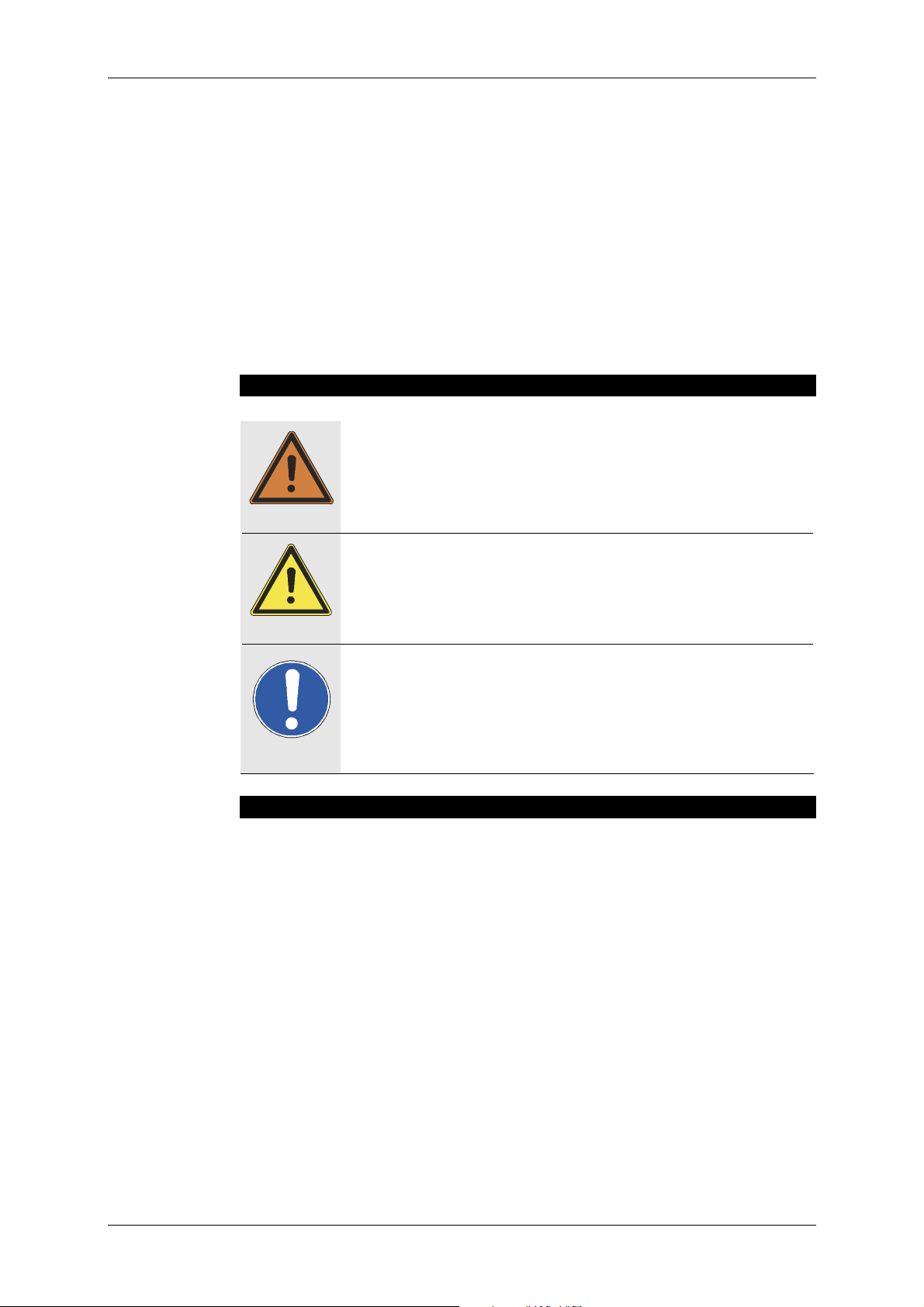
This symbol indicates the possibility of life-threatening danger and a
health risk for persons Not following these instructions may result in
serious health problems including potentially fatal injuries.
Warning
This symbol indicates a possibly dangerous situation. Not following
these instructions may cause minor injuries or cause property damage.
Caution
Important
This symbol gives instructions for the proper use of the described products. Not following these instructions may cause malfunctions or property damage.
Information about this User's Manual
User's Manual K&F ‘SP’ Full-Range Systems, Version 6.1, 23.03.2006
© by André Figula, Kling & Freitag GmbH, 2003 - 2006; all rights reserved.
All specifications in this manual are based on information available at the time of pub-
lishing for the features and safety guidelines of the described products.
Technical specifications, measurements, weights and properties are not guaranteed.
The manufacturer reserves the right to make product alterations within legal provisions
as well as changes to improve product quality.
All persons who use the speaker system must have this guide and all further
information for safe operations available to them during assembly, disassembly, and use.
We appreciate any input with suggestions and improvements for this manual. Please
send this to us at the following address:
info@kling-freitag.de or to:
KLING & FREITAG GMBH, Junkersstr.14, D-30179 Hannover
Phone +49 (0) 511 - 96 99 70, Fax +49 (0) 511 - 67 37 94
KLING & FREITAG GMBH ©2003 - 2006 Version 6.1, 19.06.2006 Page 3 of 54
Page 4

User's Manual ‘SP’ Models based upon the CA Series
Contents
Chapter
Page
1. General Safety Instructions 6
2. Introduction SP Loudspeakers 8
3. Connectors, Controls und Displays 10
4. Power Cord 13
5. Instructions for Suspending the Speakers 14
5.1 Using the ‘allsafe JUNGFALK’ Flying Points 15
6. Coverage Patterns of the SP Speakers 16
6.1 Changing the Coverage Pattern 16
7. Mounting Instructions for Speakers 17
7.1 Proper Arrangement of the Loudspeakers 17
7.2 Arrayed Speaker Systems (Cluster) 18
7.2.1 Horn not rotated 18
7.2.2 With rotated Horn 19
8. Wiring 20
8.1 Avoiding Ground Loops 20
8.1.1 What is a Ground Loop? 20
8.1.2 Avoiding Ground Loops 20
8.2 Connecting the Power Connectors to the Connecting Terminal 21
9. Configurations and Connecting Diagrams 21
9.1 Operating the Systems without C2 Controller 21
9.1.1 Full-Range Mode 21
9.1.2 Full-Range Mode with Subwoofer 22
9.2 Operations with C2 Controller 23
9.2.1 Full-Range Mode with K&F C2 Controller 23
9.2.2 2-Way Active Mode with K&F Controller C2 24
9.3 Maximum Configuration 25
10. Operating the Speakers 26
11. Touching Up Damage to Paint / Changing the Front Foam 26
12. Block Diagram of the SP Full-Range Speaker 27
13. Technical Specifications 28
13.1 CA 1001 - SP 28
13.2 CA 1201 - SP 29
13.3 CA 1215-6 - SP 30
13.4 CA 1215-9 - SP 31
13.5 CA 1515-6 - SP 32
13.6 CA 1515-9 - SP 33
KLING & FREITAG GMBH ©2003 - 2006 Version 6.1, 19.06.2006 Page 4 of 54
Page 5

User’s Manual ‘SP’ Models based upon the CA Series
Chapter
Page
14. Measuring Charts 34
14.1 CA 1001 - SP 34
14.2 CA 1201 - SP 36
14.3 CA 1215-6 - SP 38
14.4 CA 1215-9 - SP 40
14.5 CA 1515-6 - SP 42
14.6 CA 1515-9 - SP 44
15. Dimensions 46
15.1 CA 1001 - SP 46
15.2 CA 1201 - SP, CA 1215-6/-9 --- SP 46
15.3 CA 1515-6/-9 --- SP 47
16. Accessories 47
17. Regulations for Disposal 49
17.1 Germany: 49
17.2 EU, Norway, Island, and Liechtenstein (not Germany): 49
17.3 Other countries 49
18. Declaration of Conformity and International Certificates 50
18.1 Declaration of Conformity 50
18.2 EMV Certificate Guideline 89 / 336 / EWG 51
18.3 TÜV Certificate for the USA and Canada (UL 6500) 53
19. Included Safety and Mounting Instructions for Loudspeakers and Accessories
KLING & FREITAG GMBH ©2003 - 2006 Version 6.1, 19.06.2006 Page 5 of 54
Page 6
User's Manual ‘SP’ Models based upon the CA Series
1. General Safety Instructions
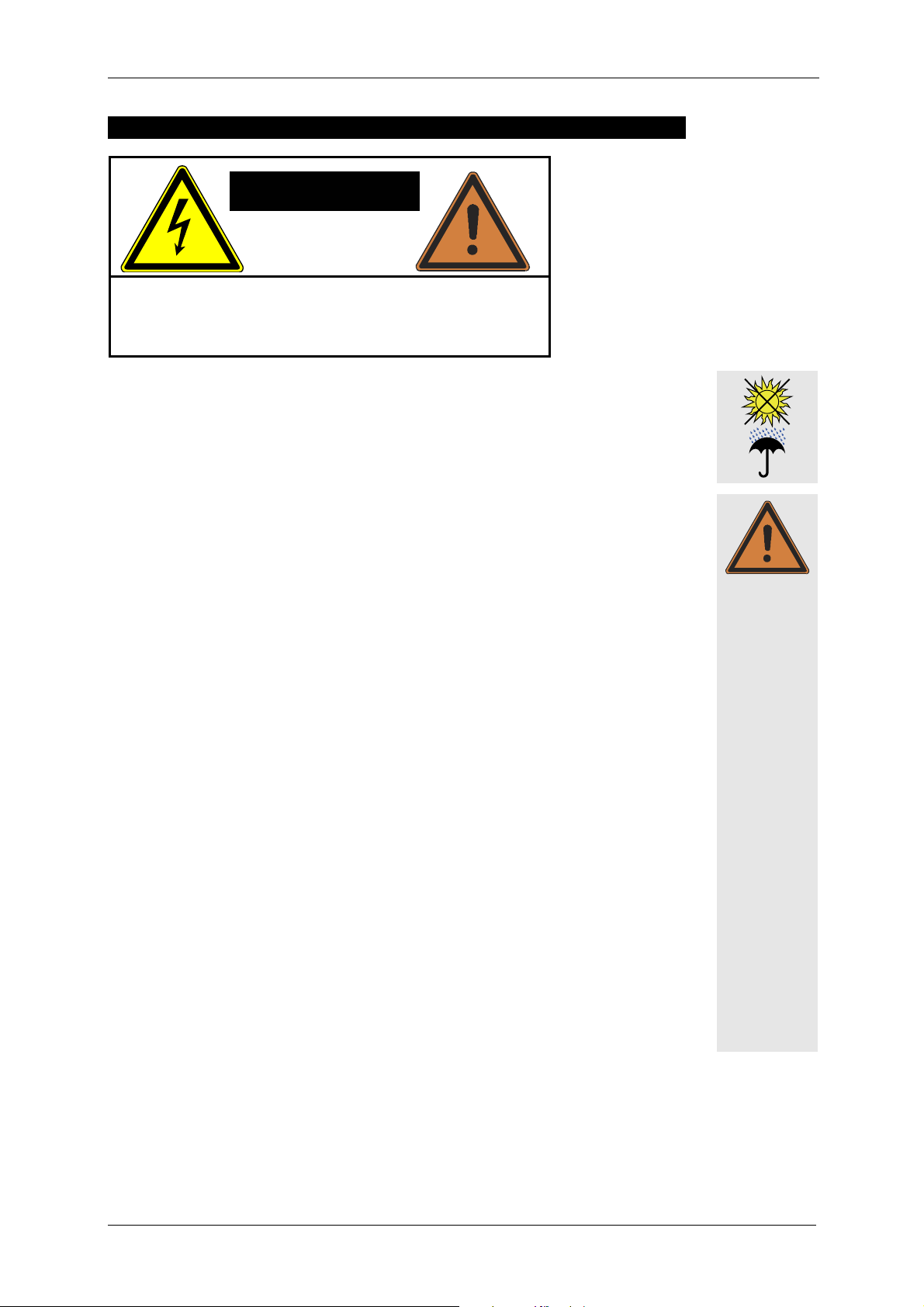
CAUTION
Risk of electric shock!
Do not open the units!
Warning: To avoid electric shock hazard, do not expose this
appliance to rain or moisture. The enclosures may only be
opened by qualified personnel!
Do not install devices in any of the following places:
− where the devices are permanently exposed to direct sunlight.
− near any heat sources and open fire. Do not put candles etc. on top of the speaker.
− where the airflow for cooling is blocked. A minimum distance of 10 cm to the heat
sink on the rear of the speaker must be kept.
− where the devices are exposed to high moisture. Objects filled with liquids, such as
a vase, must not be placed on the speaker.
− where the devices are exposed to strong vibrations and dust.
Power supply
Before connecting the AC power cable of the SP speaker, please check if the available
voltage is compatible with the operating voltage as indicated on the unit. If this is not
the case, then the unit needs to be adapted by the manufacturer or an authorized service centre. If the unit is not compatible with the available voltage, it should never be
connected! This could irreparably ruin the SP speaker.
Make sure that the power outlet supplies a ground connector, which must be connected to the unit via the PE conductor of the power cord!
All equipment, which is connected together using signal cables and has a connection to
protect ground, must be connected to a common PE conductor. If not, there is a risk of
an electric shock or the destruction of the connected equipment.
The power plug must always be used to disconnect from the power supply. Furthermore, the power plug must be easily accessible for use at all times.
Protection of electrical cables
Power cords should be laid in such a way that they are protected against footstep damages, tensile strain and against being trapped.
Transportation
When transporting the equipment, make sure that it is protected from vibrations.
Cleaning
The equipment should only be cleaned with a damp cloth when it is not plugged in.
Pauses in use
The power cord should be disconnected from the power source during longer pauses
in use.
Warning
Intrusion of objects or liquids
No objects or liquids should intrude or leak into the equipment.
KLING & FREITAG GMBH ©2003 - 2006 Version 6.1, 19.06.2006 Page 6 of 54
Page 7
User’s Manual ‘SP’ Models based upon the CA Series
Maintenance and technical service
The user should not perform any maintenance work on the equipment other than that
which is described in this manual. Repairs should be executed by a qualified service
Warning
technician only.
In the following cases, the unit should be serviced by an authorized technician only if:
− the power cord or the mains connectors have been damaged.
− objects or liquids have gotten into it.
− it was exposed to rain.
− it doesn't appear to be functioning properly.
− it has fallen down or the enclosure is damaged.
Mounting the speakers
If the weight of the speaker exceeds 25 kg then it is necessary for two people to carry it.
To prevent injury, this equipment must be securely placed on the floor or secured to the
wall according to the mounting instructions. Speakers, which are stacked, must be secured with securing straps. Please note that speakers can move as a result of vibrations.
To prevent them from falling from their mounted position, they must be secured properly.
Speakers may only be suspended by qualified personnel.
Never use signal cables or power cords for suspending, aligning or securing the systems.
When laying the connecting cables, make sure that nobody can trip.
The speakers must be hung by using at least two of the designated flying points. The
same applies when lifting and aligning the speakers.
Never hang more than two speakers under one another without using the designated
Kling & Freitag rigging equipment.
Ensure that all installation connections comply with the applicable safety guidelines and
that the size and strength are sufficient. Further instructions are in our user's manual for
assembly equipment and in the general safety instructions for speakers and assembly
equipment.
For mobile and fixed installations, use only rigging equipment from KLING & FREITAG.
Make sure to observe the included safety and mounting instructions for loudspeakers
and accessories.
Important
Caution
Unwanted interference
RF interference on the power cord or on the line signal cables may lead to unwanted
sound interference.
Damage caused by the speakers' magnetic fields
Speakers are permanently surrounded by a magnetic field, even when they are not operating. Therefore, during transport and placement of the speakers, it is important to
ensure that there is always approx. 1 m between the speakers and magnetic data media
and computer/video monitors.
The following signals may damage the speakers
− permanent high-pitched signals with high frequency and continuous noise from
feedback
− permanently distorted signals with high power.
− noises, which occur when the SP speaker is connected while equipment is being
connected, disconnected or switched on.
Preventing hearing damage
To prevent the risk of hearing damage, avoid being too close to operating speakers,
even if the volume level seems to be low enough. In general, volume levels over 90 dB
can cause hearing damage.
KLING & FREITAG GMBH ©2003 - 2006 Version 6.1, 19.06.2006 Page 7 of 54
Page 8

User's Manual ‘SP’ Models based upon the CA Series
2. Introduction SP Loudspeakers
‘SP’ denotes a new option for selected models in the K&F range of loudspeakers.
Based on selected K&F speaker systems, the ‘SP’ models are equipped with state-ofthe-art integrated driver circuits and Class D power amplifier technology. The extremely lightweight system electronics replace ponderous racks, power amplifiers,
controllers, and speaker cables.
Aside from the integrated power amplifier and input modules with controller functions, the full-range systems possess a passive crossover so that the advantageous
features provided by the K&F passive technology (all-pass filter, protection circuits)
remain usable. The frequency separation for the subwoofers is controlled by an active
110 Hz low-pass filter.
Integrated phase optimisation allows for all systems in the ‘SP Series’ to be combinable with one another. With this, the ‘SP’ speakers, when the filter section is switched
off, have a completely comparable sound to the corresponding versions without integrated power amplifier technology. Operations using the K&F C2 Controller are also
possible, which is, for example, appropriate for combined applications with equivalent
passive systems or for the use of C2 presets (clustering = Top Low Cut, Bass-Boost
etc.).
Operating the ‘SP Series’ is incredibly easy: The full-range systems transmit the complete frequency spectrum. If necessary, the ‘SP’ subwoofers in parallel operations can
provide an additional bass boost.
The Input Module
− Line signal input
− Limiter section (feed-forward RMS-limiter and peak limiter in feed-back design).
− High pass filter, 45 Hz tops, and 32 Hz subwoofers
− Low pass filter 110 Hz (only subwoofer systems)
− System specific, switchable frequency equalisation (‘FILTERS ON/ OFF’) controllable
by a covered switch on the connecting terminal
− Phase correction
− Level adjustment (countersunk level control on the connecting terminal)
The Amplifier Module
− 1 x, or 2 x 1 kW Class D state-of-the-art power amplifier
− Minimal dimensions (speaker dimensions of the models without the ‘SP’ module are
retained)
− Low weight (weight increase of 2.5 / 4 kg as compared to systems without the ‘SP’
module; and with the Line 212 --- SP, the weight even stays identical)
− High efficiency enables convection cooling, because of which bothersome fans are
unnecessary
− High fidelity (even in high frequency range) and a large power bandwidth resulting
from impedance optimisation
KLING & FREITAG GMBH ©2003 - 2006 Version 6.1, 19.06.2006 Page 8 of 54
Page 9

User’s Manual ‘SP’ Models based upon the CA Series
Modes of Operation
− Operations without external controller:
with activated filters (FILTERS ‘ON’), all K&F models in the ‘SP Series’ are combinable with one another by simply linking the signal from one speaker to the next.
− With optional K&F system controller*:
with system plug-in cards via the K&F Controller C2 or an Audio DSP*
− if used with BSS Soundweb, FDS 366, 336, 334, and XTA DP 226, 224, K&F sys-
tem parameters are available upon request
* The operation of the K&F ‘SP’ models with Controller C2 or Audio DSP is recommended for uses in which special filter presets are advisable, i.e. in combination with
passive systems of the ‘CA Series’, in cluster operations (top low cut), when bass and
high boost are necessary, adjustment to the room acoustics (EQ), etc.
The following K&F ‘SP’ speakers are available:
Full-range systems: CA 1001 - SP,
CA 1201 - SP,
CA1215-6 - SP, CA 1215-9 - SP
CA 1515-6 - SP, CA 1515-9 - SP
LINE 212-6 - SP, LINE 212-9 --- SP
Subwoofers: SW 112 - SP, SWi 112 - SP,
SW 115E - SP, SWi 115E - SP,
SW 118E - SP, SWi 118E - SP,
SW 215E - SP
KLING & FREITAG GMBH ©2003 - 2006 Version 6.1, 19.06.2006 Page 9 of 54
Page 10
User's Manual ‘SP’ Models based upon the CA Series
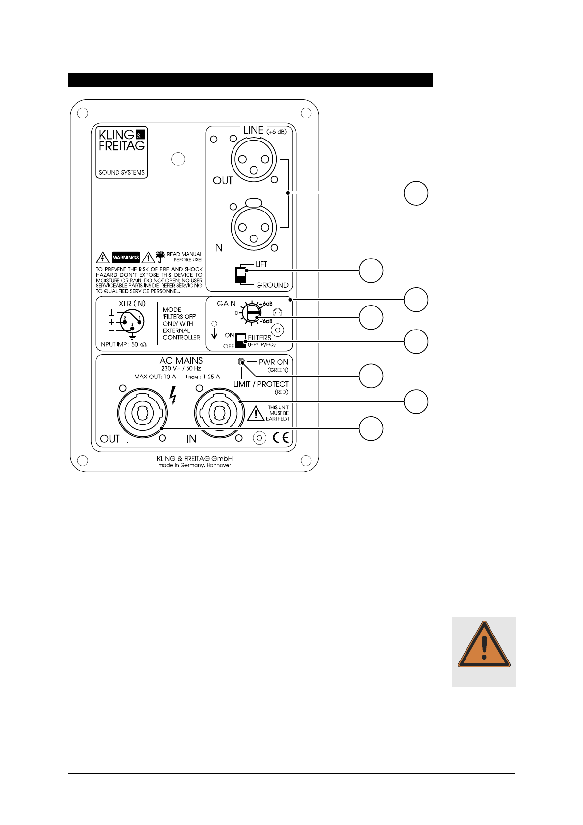
3. Connectors, Controls und Displays
1
2
3
4
6
8
1) LINE IN and LINE OUT (+6 dB)
Electronically balanced input and output connectors. Use the XLR female connector
(marked ‘IN’) as input. The parallel-wired XLR male connector (‘OUT’) is for connection to further ‘SP’ loudspeakers.
2) GROUND LIFT
When the ‘Ground Lift’ switch is set to LIFT, pin 1 of the LINE IN connector (ground)
is not connected to the chassis ground of the integrated amplifier module. The
ground connection between LINE IN (XLR male) and LINE OUT (XLR female) is maintained. The use of the ‘Ground Lift’ switch is sometimes necessary in dealing with
hum problems (see chapter 8.1 )
Nev
Never tape over the protective earth on the plug
er tape over the protective earth on the plug ---
NevNev
er tape over the protective earth on the plug er tape over the protective earth on the plug
3) PROTECTIVE COVER
--- danger to life
danger to life!
------
danger to life danger to life
5
7
Warning
The protective cover prevents unwanted adjustment of the gain control and filter
ON / OFF switch. The cover has a snap-in lock. In order to reach the controls beneath, turn the cover sharply in the direction of the arrow.
KLING & FREITAG GMBH ©2003 - 2006 Version 6.1, 19.06.2006 Page 10 of 54
Page 11
User’s Manual ‘SP’ Models based upon the CA Series
4) GAIN CONTROL (± 6 dB)
a) The gain control can be used to adjust the input level of the amplifier module
by ± 6dB. It serves to balance the volume levels of the various systems. In order to avoid overloading the input circuit or mixer’s output circuit, it should
normally be set in the case of K&F full-range systems at 0 dB (centre notch
setting).
b) When operating with C2 Controller, set the input level of the amplifier mod-
ule on the C2 Controller (Input Gain). The gain control on the SP speaker
should be set at 0 dB (centre notch setting). One exception to this rule is a
cluster arrangement, in which the inner speakers should be set at a lower
level than the outer ones. In this case the level of the gain control on the inner SP speakers can be adjusted downwards accordingly.
When operating with additional bass systems it is very important that the respective volume levels between the top speakers and the bass systems are correctly
balanced. To this end the sound engineer should check the volume levels during
the set-up and adjust them accordingly. When setting up a system without C2
Controller this adjustment should be carried out using the gain control of the SP
subwoofer; in the case of a system with C2 Controller use the ‘Sub Gain’ control
on the C2 Controller.
Normally we recommend the following settings*
gain control subwoofer / sub gain control C2
1 x top / 1 x subwoofer + 6 dB
1 x top / 2 x subwoofer + 0 dB
1 x top / 1 x SW 215 E - SP + 0 dB
* These details may vary due to different room geometries.
The position of a bass speaker is also crucial for its actual sound level. A bass
speaker, which is on the floor, can be a few decibels louder than a flown bass system because of the floor reflections. Because of this, a sound engineer must always
fine-tune the system using the corresponding gain controls.
5) FILTERS ON / OFF (High-Pass / Low-Pass / Equalizer)
This switch turns the filter in the SP module on (‘ON’), or off (‘OFF’).
a) The switch should always be in the ‘ON’ position when the speakers are being
driven without
C2 Controller.
b) The switch should always be in the ‘OFF’ position when the speakers are being
driven with
C2 Controller.
The filters consist of:
− high-pass: protects the speakers against mechanical stress due to frequen-
cies outside the speaker's frequency range (protection against subsonic frequencies)
− EQ: filter for basic equalisation, optimising the frequency response of the
speaker systems.
Furthermore the SP filter module has a phase alignment, which prevents loss of
certain frequencies due to phase shift between mid-high and bass systems.
Thus the combination of all available K&F mid-high SP systems with all K&F
bass SP systems is possible, and 100% phase compatibility with all K&F speakers operating in conjunction with the K&F C2 Controller in the ‘2-way active’
mode is guaranteed.
KLING & FREITAG GMBH ©2003 - 2006 Version 6.1, 19.06.2006 Page 11 of 54
Page 12
User's Manual ‘SP’ Models based upon the CA Series
6) LED POWER ON (GREEN) and LIMIT / PROTECT (RED)
The LED is dual-purpose:
a) When the LED is green, the speaker is connected to the supply voltage and
ready for operation
b) The LED will turn red if…
…the input signal is so high that the internal limiters reduce its level.
The limiters consist of a peak limiter, which limits the peaks of the signal,
and an RMS / thermal limiter, which continuously regulates excessive levels.
During normal operation the red light may occasionally illuminate briefly. It
does indicate that the level peaks are limited by the limiter circuit. The peak
performance of the speaker has then been reached.
Should the red light come on more frequently or remain illuminated, the
output level of the mixer should be reduced. When speakers with and
without SP module are in operation simultaneously, the gain control on the
SP speaker can be turned down, provided the level is sufficient for the
other power amplifiers. The limiter protects the speaker from damage due
to excessive levels.
c) The LED stays permanently red, if…
…the protection circuitry of the integrated power amplifier cuts in and as a
result no or a too low signal reaches the speaker (Protect Mode).
The protection circuitry switches off the integrated power amplifier,…
− …if the temperature of the amplifier module is too high. As soon as
the temperature falls below the critical value, the amplifier module is
switched on again automatically. Excessive temperatures can be caused for example by inadequate ventilation of the heat sink. Make sure
that the heat sinks are not covered or positioned directly against a
wall.
− …if the output impedance is too low or in the case of a short circuit,
caused for example by a defective chassis or a faulty component on
the crossover.
− …if the amplifier has an internal fault. The SP amplifier module checks
that all is functioning correctly during operation. As soon as a fault becomes apparent the module switches into protect mode.
Measures to be taken when LED is red:
Fault Measure Function
LED remains red or flickers
continually during operation
No or too low output signal,
LED shows red in spite of
reduced mixer level.
No or too low output signal,
LED stays red after cooling
Reduce output level on mixer until LED
goes out or flickers only occasionally
Allow to cool. The amplifier module
switches itself on after a few minutes.
Provide sufficient ventilation.
Have loudspeaker checked by
authorized service technician.
Limiter
Temperature protection
Other protection
down.
KLING & FREITAG GMBH ©2003 - 2006 Version 6.1, 19.06.2006 Page 12 of 54
Page 13
User’s Manual ‘SP’ Models based upon the CA Series
7) AC MAINS ‘IN’
Connect this PowerCon socket using the mains cable supplied to a max. 16 A fused
mains socket, paying particular attention to the stated mains voltage! Connection
Important
Warning
to an incorrect mains voltage can result in irreparable damage!
8) AC MAINS ‘OUT’
Socket for connections to further equipment such as further speakers with SP module. Use only connection cables, which conform to your national safety regul
Use only connection cables, which conform to your national safety regula-
Use only connection cables, which conform to your national safety regulUse only connection cables, which conform to your national safety regul
tions
tions.
tionstions
Maximum power consumption: 230 V: 10 A / 2300 W
115 V: 10 A / 1150 W
a-
a-a-
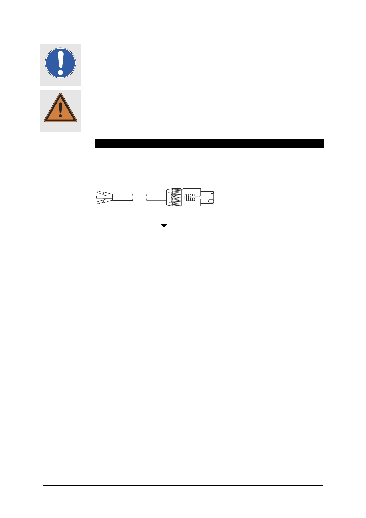
4. Power Cord
In Germany, a pre-constructed ready for use power cord is included in the delivery.
For deliveries to foreign countries, a pre-constructed power cord incl. PowerCon plug is
included. Because of the different standards abroad, the power plug is not included.
This must be subsequently assembled only by qualified electrical specialists.
brown = BN = L
green / yellow = GNYE =
blue = BU = N
KLING & FREITAG GMBH ©2003 - 2006 Version 6.1, 19.06.2006 Page 13 of 54
Page 14
User's Manual ‘SP’ Models based upon the CA Series
5. Instructions for Suspending the Speakers
Only trained personnel may suspend speaker systems.
Pay attention the accompanying safety and assembly instructions carefully as
well as the required safety factors. Please follow the corresponding national
safety regulations.
Speaker systems, whether single or connected to one another, must always be secured
to a second separate point, even if two rigging points are used for suspending the
speaker system!
Ensure that all connections are secured to prevent their detaching on their own and that
only admissible statically tested and sufficiently sized connecting devices, ropes and
chains are used.
CA 1001
CA 1001 ---- SP:
CA 1001 CA 1001
SP:
SP: SP:
We recommend using the M8 threads only for mounting stand adapters and TV-spigot
adapters. The M10 threads should be used for mounting the CA 1001 with adjustable
speaker mounts or U-mounts only.
Eyebolts can be attached to the M8 and M10 threads in order to suspend the speakers,
if they are dimensioned sufficiently (safety factor 12) and are used as described by the
manufacturer.
Pease note:
Warning
The M10 thread inserts can only support weights up to 50 kg each.
The M8 thread inserts can only support weights up to 12.5 kg each.
Speakers with ‘allsafe JUNGFALK’ flying points:
A maximum load of 50 kg may be suspended from the two ‘allsafe JUNGFALK’ of one
speaker. This means a maximum additional load of 25 kg on each ‘allsafe JUNG-
FALK’ flying point.
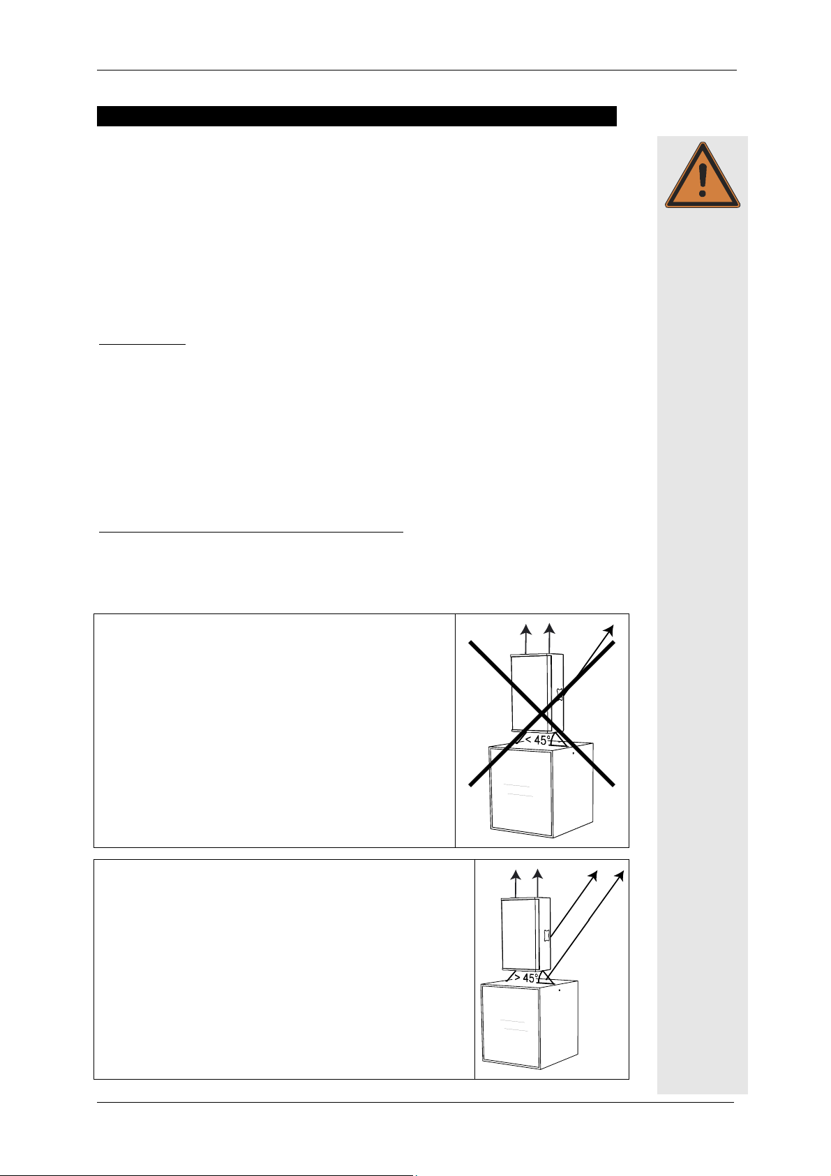
Wrong:
− The angle of the rope/chain in relation to the lower
speaker is less than 45°. This causes the load on the flying points to exceed the permissible level.
Right:
− A two-point suspension was selected. Each speaker is se-
cured with an additional safety device.
− The angle of the rope/chain in relation to the lower
speaker is greater than 45°. This maintains a permissible
load on the flying points.
KLING & FREITAG GMBH ©2003 - 2006 Version 6.1, 19.06.2006 Page 14 of 54
Page 15
User’s Manual ‘SP’ Models based upon the CA Series
5.1 Us
Using the ‘allsafe JUNGFALK’ Flying Points
ing the ‘allsafe JUNGFALK’ Flying Points
UsUs
ing the ‘allsafe JUNGFALK’ Flying Pointsing the ‘allsafe JUNGFALK’ Flying Points
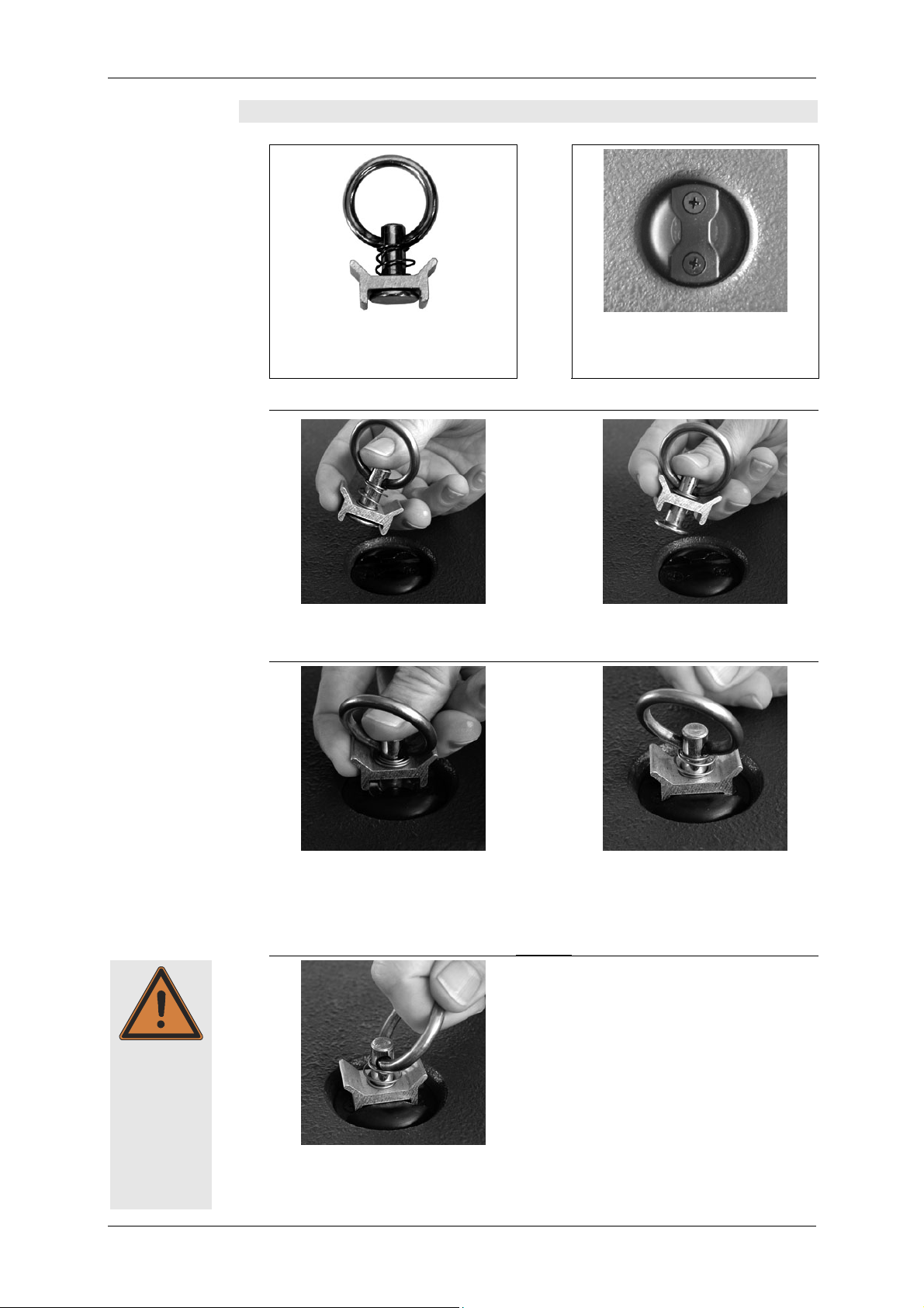
Single Stud Fitting
Used as fastener to the ‘allsafe
JUNGFALK’ flying point.
1.)
Take the single stud fitting in one
hand...
3.)
‘allsafe JUNGFALK’ flying point
Receptacle for special fasteners.
2.)
... and push the locking device up
against the spring tension.
4.)
Put the flat head of the holding
bolt into the guiding of the flying
point.
Release the locking device when
the single stud fitting is located in
the middle of the flying point.
Make sure that the locking device
clicks into place.
5.)
Warning
Check that the single stud fitting is
securely fastened and cannot be
pulled out.
KLING & FREITAG GMBH ©2003 - 2006 Version 6.1, 19.06.2006 Page 15 of 54
Page 16
User's Manual ‘SP’ Models based upon the CA Series
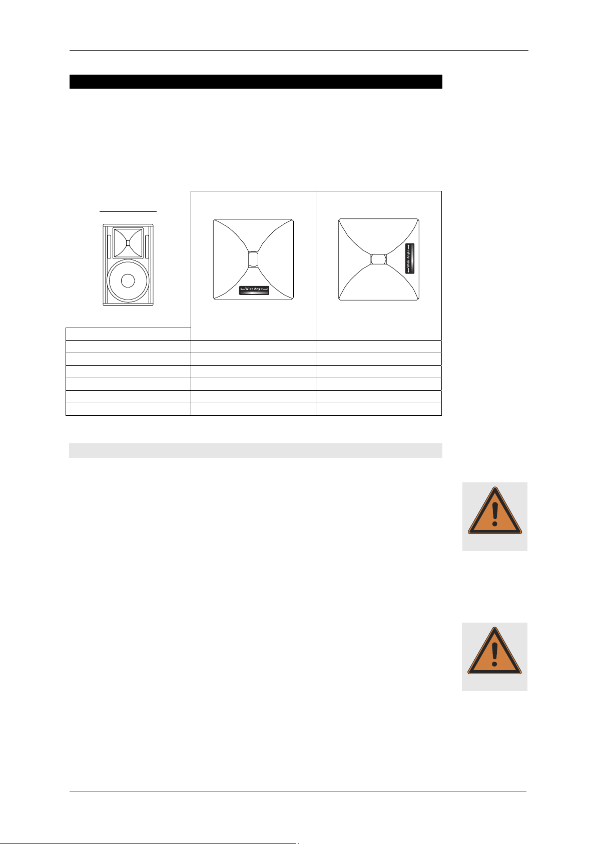
6. Coverage Patterns of the SP Speakers
The mid-high systems can be operated in a vertical or horizontal (i.e. as a stage monitor) position. The coverage pattern of the speakers can be adapted to special needs by
a 90° rotatable horn.
The table below shows the coverage angles of a standing speaker: To determine the
coverage pattern of the high frequency horn, shine a flashlight through the front
covering at the level of the horn. You will find a silver stripe that determines the position and coverage angles of the horn.
DEFINITION:
Standing speaker:
Model
CA 1001 - SP 85° h x 55° v 55° h x 85° v
CA 1201 - SP 90° h x 60° v 60° h x 90° v
CA 1215-6 - SP 65° h x 50° v 50° h x 65° v
CA 1215-9 - SP 90° h x 50° v 50° h x 90° v
CA 1515-6 - SP 65° h x 50° v 50° h x 65° v
CA 1215-9 - SP 90° h x 50° v 50° h x 90° v
Horn not rotated
Horn rotated
6.1 Changing the Coverage Pattern
To turn the horn, follow these steps:
1) Disconnect the power plug!
2) Remove the four grille mounting screws on the top and bottom of the speakers
with a 3 mm Allen key and remove the grille from the speaker enclosure.
3) Make sure that no objects fall into the enclosure!
4) Remove the screws from the high frequency horn (also using a 3 mm allen key).
Loosen the high frequency horn by using both hands, palms to the outside, to
grasp into the horn and lift the horn with even pressure from the palms of your
hands towards the outside. Never use a screwdriver or similar objects to reach behind the edge of the horn, as this could damage it.
5) Rotate the horn 90° and screw the horn on tightly again (do not force it!)
6) Screw the grille on tightly.
If the coverage angle needs to be changed often, make sure that the horn is not always
rotated in the same direction, as the connecting cables, when twisted, may cause the
contacts of the driver to become loose. Open wires may hit other live parts: Danger
of electrical shock.
Warning
Warning
KLING & FREITAG GMBH ©2003 - 2006 Version 6.1, 19.06.2006 Page 16 of 54
Page 17
User’s Manual ‘SP’ Models based upon the CA Series
7. Mounting Instructions for Speakers
Mount the speakers securely. To avoid injury or damage, always be sure to mount the
speakers securely so that they do not fall. Speakers, which are stacked, must be secured
with securing straps. When laying the connecting cables, make sure that nobody can
Warning
trip.
The stability of stacked systems (also valid for the use of stands and distance rods!) is
contingent upon the following stability requirement. These conditions must, therefore,
be guaranteed by the user:
Stacked systems may not fall over even if they are inclined by 10° in each direction. If this requirement is not fulfilled, then it is necessary to take steps to
achieve compliance. Possible measures include strapping it to an appropriate
base structure or fastening it using safety straps.
7.1 Proper Arrangement of the Loudspeakers
Be aware of the fact that the logical targeted alignment of this high quality speaker
system can lead to a significant qualitative increase in the acoustic result. It is not possible to make generalities about the alignment of specific systems because the room has
a substantial influence on the signal and the audible result.
As a rule, the mid- and high-transducers of loudspeakers should be mounted above the
audience's face value, so that the sound distribution cannot be shadowed.
In many cases it is advisable to mount a loudspeaker higher, so that the sound will be
distributed throughout the room more evenly. Low standing systems result in a greater
difference in volume between front and back seats than higher standing systems.
Please note that this is only a general guideline and the best possible result may vary
from room to room.
To simulate the correct alignment of the speakers beforehand, there are various programs such as ‘Ease’ or ‘Ulysses’. The Kling & Freitag speaker system data is available for
download on our website www.kling-freitag.de. The system data for SP speakers is
identical to the data for the corresponding speakers without SP option.
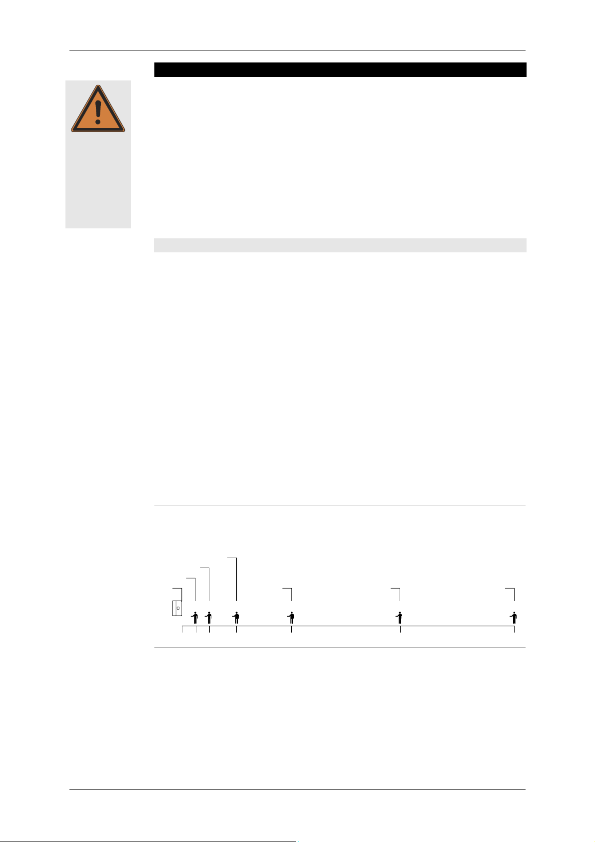
The following graphics will assist in making a rough estimate as to the distance range of
SP full-range systems. The graphics only take into consideration the sum of the direct
sound and not the influence of the room. Because of this there can, in some cases, be
noticeable deviation.
Distance range of SPL (direct sound level):
-18 dB
-12 dB
0 dB
-6 dB
-24 dB -30 dB
2m 4m 8m 16m 32m 50m
-34 dB
KLING & FREITAG GMBH ©2003 - 2006 Version 6.1, 19.06.2006 Page 17 of 54
Page 18

User's Manual ‘SP’ Models based upon the CA Series
7.2 Arrayed Speaker Systems (Cluster)
If the loudspeakers are operated through the optional K&F C2 System Controller, we
recommend to turn on the 'Top Low Cut' switch for clustered operation. Thus the frequency response for this application can be optimised (see also K&F C2 user's manual).
When operating the systems without the K&F C2 System Controller in a clustered configuration, the signal level of frequencies below 300 Hz should be reduced by 3-4 dB.
7.2.1 Horn not rotated
Winkel 2
Horn not
rotated
Standing
speaker
Winkel 1
A smaller angle 3
results in a smaller
vertical coverage
angle but increases
the sound power
level.
between the sides of the
speakers
between middle axes
Combination Angle 1 Angle 2 Angle 3
CA 1001 with
CA 1001
CA 1201 with
CA 1201
CA 1215-6 with
CA 1215-6
CA 1215-6 with
CA 1215-9
CA 1215-9 with
CA 1215-9
CA 1515-6 with
CA 1515-6
CA 1515-6 with
CA 1515-9
CA 1515-9 with
CA 1515-9
not generally recommended*
45°-55°
not generally
recommended*
30° 40°
35° 45°
40°-50°
not generally
recommended*
30° 40°
35° 45°
40°-50°
not generally
recommended*
Application Increasing the hori-
zontal coverage an-
gle, e.g. for wide
audience planes
50°
recommended*
recommended*
recommended*
Increasing the hori-
zontal coverage
angle and sound
power level for
larger distances
55°-65°
not generally
50°-60°
not generally
50°-60°
not generally
30°
20°-35
20°-30°
Increasing the vertical
coverage angle, e.g.
for covering balco-
nies or for increased
sound power level
for larger distances
Winkel 3
*If several 90° systems are clustered, unwanted interference effects may appear. As a
result, we do not generally recommend clustered configurations of CA 1001, CA
1201, CA 1215-9 and CA 1515-9 systems. If wide angles are to be covered, we recommend the use of several 60° or 65° systems in one cluster.
KLING & FREITAG GMBH ©2003 - 2006 Version 6.1, 19.06.2006 Page 18 of 54
Page 19

User’s Manual ‘SP’ Models based upon the CA Series
7.2.2 With rotated Horn
Winkel 2
Horn
rotated
Standing
speaker
Winkel 1
A smaller angle 3
results in a smaller
vertical coverage
angle but increases
the sound power
level.
Combination Angle 1 Angle 2 Angle 3
CA 1001 with
CA 1001
CA 1201 with
CA 1201
25° 35° Not recommended
CA 1215-6 with
CA 1215-6
CA 1215-6 with
CA 1215-9
CA 1215-9 with
CA 1215-9
CA 1515-6 with
20° 30°
CA 1515-6
CA 1515-6 with
CA 1515-9
CA 1515-9 with
CA 1515-9
Application Increasing the hori-
zontal coverage an-
gle, e.g. for wide
audience planes
30° Not recommended
30°-40°
30°-45°
Not recommended
30°-40°
30°-45°
Not recommended
Increasing the hori-
zontal coverage angle
and sound power
level for larger dis-
tances
Increasing the verti-
cal coverage angle,
e.g. for covering
balconies or for
increased sound
power level for
larger distances
Winkel 3
KLING & FREITAG GMBH ©2003 - 2006 Version 6.1, 19.06.2006 Page 19 of 54
Page 20

User's Manual ‘SP’ Models based upon the CA Series
8. Wiring
Before connecting your SP system as shown in chapter 9, be sure to switch off all connected appliances and turn down all level controls.
− We recommend the use of high-quality cables provided by KLING & FREITAG.
− For connections to the line level inputs, please use 2-pin shielded microphone cable
with high-quality connectors.
− Avoid ground loops
− Make sure that the pin assignment of the line level connectors is correct (2 + / 3 - / 1 ┴).
8.1 Avoiding Ground Loops
8.1.1 What is a Ground Loop?
Every component of a P.A. or Hi-Fi System has its own internal 0V reference (ground). This
point is often connected to the protective earth connector (PE / Ground). If two or more
units are connected to one another with a line level audio cable, there may be a ground
connection through the ground of the power supply cable (yellow-green) as well as
through the shielding of the audio cable. The voltage difference between these two
ground points causes audible interference to come from the speaker.
8.1.2 Avoiding Ground Loops
If there is a loud humming or buzzing after the ‘SP’ System has been connected, then
set the ‘Ground Lift’ switches on the rear of the ‘SP’ speakers to the ‘Lift’ position (chapter:3 / section 2).
If the noise is still audible, check if
1. the noise is caused by a ground loop before the speakers (e.g. mixing console,
effects or equalizers).
2. the system or parts of the system are connected to an ‘unclean’ power supply meaning one which is also running large motors or lighting systems. An ‘unclean’ supply voltage, electrostatic and electromagnetic fields can cause interference.
Please observe the following basic rules:
− Never !!! try to avoid a ground loop by disconnecting or taping the ground
contact at the connector! Extremely dangerous!
− If possible, only use high-quality audio appliances with balanced signal outputs and
power cables with PE connectors.
− Use high-quality cables with good shielding.
− The point of ground for all connected components should merge at one central
point. The power connections should lead out in a radial manner from one point
and not be linked from one unit to the next.
− When installing appliances that create strong electrostatic or electromagnetic fields
(large transformers, switch-mode power supplies), maintain some distance from
other audio appliances. In extreme cases, the only solution is to create a completely
independent ‘audio ground’; in other cases, it is sufficient to connect a filter in front
of the audio equipment.
Warning
KLING & FREITAG GMBH ©2003 - 2006 Version 6.1, 19.06.2006 Page 20 of 54
Page 21

User’s Manual ‘SP’ Models based upon the CA Series
8.2 Connecting the Power Connectors to the Connecting Terminal
1.
Warning
2.
1.
Only use the supplied power cable and connect it to a mains outlet with a 16 A fuse.
2.
3.
See instructions in chapter 4 ‘Power Cord’ on page 13.
9. Configurations and Connecting Diagrams
9.1 Operating the Systems without C2 Controller
The full-range system can be used alone or in conjunction with an SP subwoofer. The
subwoofer has an integrated filter for use in this mode, which limits the bandwidth.
The full-range system is protected against low frequency (subsonic) signals by a highpass filter and when used with bass speakers it is phase aligned with the subwoofers by
means of alignment filters.
9.1.1 Full-Range Mode
This mode of operation is ideal for speech and music applications without the need for
a high bass content. Should more bass be needed, the bass level can be increased between 50 and 80 Hz at the mixing console.
The switch ‘FILTERS’ on
the SP speaker must be
at ‘ON’ in this mode.
If you are operating a mid-range system in a cluster (speakers arranged in close proximity) reduce the frequencies below 300 Hz by 3-4 dB! (The K&F C2 Controller has for
this purpose a ‘top low cut’ switch.)
LINE
AC-MAINS
INPUTChannel 2 Channel 1
AC ~ 16 A max.AC ~ 16 A max.
LINE
AC-MAINS
KLING & FREITAG GMBH ©2003 - 2006 Version 6.1, 19.06.2006 Page 21 of 54
Page 22

User's Manual ‘SP’ Models based upon the CA Series
9.1.2 Full-Range Mode with Subwoofer
You can link the input signal (for example from the mixer) from one loudspeaker to
another. It makes no difference whether the input signal reaches the bass speaker first
and is then transmitted to the mid-high speaker or the other way around.
The switch ‘FILTERS’ on
the SP speaker must be
at ‘ON’ in this mode.
If you are operating a mid-range system in a cluster (speakers arranged in close proximity) reduce the frequencies below 300 Hz by 3-4 dB! (The K&F C2 Controller has for
this purpose a 'Top-Low Cut' switch.)
AC ~ 16 A max.
Channel 1
INPUT
Channel 2
LINE
AC-MAINS
LINE
AC-MAINS
To next
'SP'-Top
or Bass
AC ~ 16 A max.
LINE
AC-MAINS
LINE
AC-MAINS
To next
'SP'-Top
or Bass
KLING & FREITAG GMBH ©2003 - 2006 Version 6.1, 19.06.2006 Page 22 of 54
Page 23

User’s Manual ‘SP’ Models based upon the CA Series
9.2 Operations with C2 Controller
The frequency range of the SP speakers with filters switched off (FILTERS 'OFF') is 100%
identical to the frequency range of the corresponding K&F speakers without SP module
(in the case of subwoofers the models without XO). This means that the speakers can
be operated with C2 Controller using the relevant plug-in system cards, and the user
can take full advantage of such features as bass boost in full-range mode, optimisation
for cluster operation (top low cut), high boost and sub-mono functions.
9.2.1 Full-Range Mode with K&F C2 Controller
The switch ‘FILTERS’ on
the SP speaker must be
at ‘OFF’ in this mode.
The ‘Sense’ cables on the C2 Controller do not need to be connected as the SP speakers
have their own limiters!
The countersunk switch ‘Full-Range Mode’ on the C2 Controller should be pressed and
the LED assigned to it should light up. The countersunk switch ‘Full-Range Mode’ on the
C2 Controller should be pressed and the LED assigned to it should light up.
If you are using the mid-high systems in a cluster (speakers in close proximity), press the
‘Top Low Cut’ switch on the C2 Controller.
To next
'SP'-Top
LINE
AC-MAINS
LINE
AC-MAINS
AC ~ 16 A max. AC ~ 16 A max.
Rear
240V / 50Hz
CE
FUSE: 100mA / SLOW BLOW
KLING &
FREITAG
SOUND SYSTEMS
CH1 TOP OUT
CH1 SUB OUT CH2 TOP OUTCH2 SUB OUT
SER No.
REMOTE CONTROL
MADE IN GERMANY
KLING &
FREITAG
CH2 SUB AMP
CH1 TOP AMPCH1 SUB AMPCH2 TOP AMP CH1 INPUT
CHANNEL 2 LINKCHANNEL 2 INCHANNEL 1 IN CHANNEL 1 LINK
Channel 1Front
INPUT
Channel 2
AC-MAINS
GND
LIFT
To next
'SP'-Top
LINE
CH2 INPUT
TOPHF
BOOST
LOW CUT
SUB
GAIN
INPUT GAIN
LINE
AC-MAINS
AMP RETURN CH2 AMP RETURN CH1
-LF+
L
FULLRANGE
SUB
A
T
N
I
N
MODE
MONO
G
G
I
M
I
I
S
S
L
P
B
B
U
U
O
T
S
S
1
1
1
1
H
H
H
H
C
C
C
C
-HF+C2-LF+-LF+ -HF+ -LF+
SYSTEM
CONTROLLER
L
L
L
A
A
A
SYSTEM
T
T
T
I
N
I
I
N
C2
CONTROLLER
G
M
M
G
I
M
I
I
I
I
S
L
L
S
L
P
P
P
B
B
R
U
U
O
O
O
E
T
T
T
S
S
2
2
2
2
W
H
H
H
H
O
C
C
C
C
P
KLING & FREITAG GMBH ©2003 - 2006 Version 6.1, 19.06.2006 Page 23 of 54
Page 24

User's Manual ‘SP’ Models based upon the CA Series
A
9.2.2 2-Way Active Mode with K&F Controller C2
The switch ‘FILTERS’ on
the SP speaker must be
at ‘OFF’ in this mode.
The ‘Sense’ cables on the C2 Controller do not need to be connected as the SP speakers
have their own limiters!
The countersunk switch ‘Full-Range Mode’ on the C2 Controller should not be pressed
and the LED assigned to it should not light up.
If you are using the mid-high systems in a cluster (speakers in close proximity), press the
‘Top Low Cut’ switch on the C2 Controller.
C ~ 16 A max.
Rear
CE
FUSE: 100mA / SLOW BLOW
KLING &
FREITAG
SOUND SYSTEMS
CH1 SUB OUT CH2 TOP OUTCH2 SUB OUT
CH1 TOP OUT
AC-MAINS
AC-MAINS
To next
'SP'-Top
LINE
To next
'SP'-Bass
LINE
LINE
AC-MAINS
LINE
AC-MAINS
To next
'SP'-Bass
To next
'SP'-Top
AC ~ 16 A max.
KLING &
SER No.
FREITAG
GND
REMOTE CONTROL240V / 50Hz
MADE IN GERMANY
CH2 SUB AMP
LIFT
CH1 TOP AMPCH1 SUB AMPCH2 TOP AMP CH1 INPUT
CHANNEL 2 LINKCHANNEL 2 INCHANNEL 1 IN CHANNEL 1 LINK
CH2 INPUT
INPUT GAIN
BOOST
SUB
GAIN
AMP RETURN CH2 AMP RETURN CH1
-LF+
FULLRANGE
TOPHF
SUB
LOW CUT
MODE
MONO
-HF+C2-LF+-LF+ -HF+ -LF+
SYSTEM
CONTROLLER
L
L
L
L
A
A
A
A
SYSTEM
T
T
T
T
N
N
I
I
N
I
N
I
C2
CONTROLLER
G
G
M
M
G
M
G
M
I
I
I
I
I
I
I
I
S
S
L
L
S
L
S
L
P
P
P
P
B
B
B
B
R
U
U
U
U
O
O
O
O
E
T
S
T
S
T
T
S
S
1
2
1
1
1
2
2
2
W
H
H
H
H
H
H
H
H
O
C
C
C
C
C
C
C
C
P
Channel 1Front
INPUT
Channel 2
KLING & FREITAG GMBH ©2003 - 2006 Version 6.1, 19.06.2006 Page 24 of 54
Page 25

User’s Manual ‘SP’ Models based upon the CA Series
9.3 Maximum Configuration
It is possible to use a large number of SP speakers in parallel simultaneously, however,
this number is limited according to the permitted minimum load impedance of the signal source (e.g. mixer, equalizer, etc.).
The total input impedance of all SP speakers must be larger than the permitted minimum load impedance of the signal source. If no manufacturer’s recommendations can
be found, take the output impedance of the signal source. In this case we recommend a
total input impedance at least 10 times higher than the stated output impedance of the
Important
signal source.
(The output impedance of your signal source can normally be found under ‘Technical
Specifications’ in the manufacturer’s instruction manual.)
Definition:
OUT
IN
MAX
=
=
source signal of impedance output R
50.000Ω 50kΩ speaker - SP impedance input R
===
speakers SP of number drecommende maximum n
The maximum number of SP speakers can be calculated with this formula:
n
<
MAX.
Example:
R
OUT
n
<
MAX.
MAX.
50
Ω
R
IN
10
×
R
k
=
R
OUTOUT
10
×
Ω= 75
<⇒
OUT
R
IN
10
×
66n
000.50
Ω
Ω
1075
xR
=
KLING & FREITAG GMBH ©2003 - 2006 Version 6.1, 19.06.2006 Page 25 of 54
Page 26

User's Manual ‘SP’ Models based upon the CA Series
10. Operating the Speakers
− Switch off all equipment and make sure that the SP speakers are not connected to a
power source.
− Connect your SP systems in accordance with the preceding connection diagrams.
Use only mains cables, which comply with your national safety regulations.
− Upon completing the wiring, ensure that the connected speakers are working in phase. To
do so, use i.e. a phase checker. A phase error can also be recognized when the connected
channels are used simultaneously. During simultaneous use the bass frequencies become
notably quieter or the mid-frequencies such as voices cannot be located.
− Switch on first the peripheral units (mixer, effects, etc.), then, if used, the C2 Controller
and connect lastly
Otherwise switching noises may damage the system.
the SP loudspeakers. Always use the before mentioned switching order.
− If there is interference, turn off all appliances in the reverse order and check all cable
connections (see chapter 8.1 ). Next, turn up the C2 Controller, if used, and all other peripheral units, and check these for interference.
−
Your system should now be ready for operation.
− You can now turn up the level on the mixer.
− If you are using additional bass systems you can now balance the respective volume
levels of the top speakers and bass systems. A fine adjustment of the system without C2
Controller can be obtained using the gain control on the SP loudspeakers (not on the
mixer!). To adjust the system with C2 Controller use the ‘Sub Gain’ control of the C2
Controller (see chapter 3 / section 2).
− When switching off the system first disconnect the ‘SP’ loudspeakers. Then you can switch
off the remaining units.
11. Touching Up Damage to Paint / Changing the Front Foam
Although the PU structured paint used by KLING & FREITAG is extremely resistant, we
recommend using protective covers or cases to help avoid damaging the paint during
i.e. continuous mobile use. If paint damage occurs despite these precautions, it can be
touched up by using commercial acrylic paint in the appropriate RAL colour of the
speaker. To replace the filter foam, send the front grille incl. foam to KLING & FREITAG
GmbH. Upon payment for expenses, the grille with the new covering will be returned.
Warning
Important
KLING & FREITAG GMBH ©2003 - 2006 Version 6.1, 19.06.2006 Page 26 of 54
Page 27

User’s Manual ‘SP’ Models based upon the CA Series
12. Block Diagram of the SP Full-Range Speaker
±12 V DCPOWER 'ON '
CIRCUIT
POTECTIO N
AMP
DIGITAL
POWER SUPPLY
FUSE
THRESHOLD PEAKTHRESHOLD RMS
SIGNAL
LIMITER
RMS
+ PEAK
ERROR
ERROR
CONTROLLER
LED
BI-CO LOUR
HF-
CORRECTION
PASSIVE C ROSSOVER
LOUDSPEAKER AMPLIFIER UNIT
HF
LF
'FILTERBOARD FULLRANGE'
'
F
F
O
'
/
'
N
O
'
S
R
E
T
L
I
F
PHASE-CORRECTION
HI-PASS
HI-PASS
±
6 dB
GAIN
MAINBOARD
SCHEMATIC FULL RANGE LOUDSPEAKER 'SP'
T
F
I
L
L
L
N
N
KLING & FREITAG GMBH ©2003 - 2006 Version 6.1, 19.06.2006 Page 27 of 54
D
N
G
2
3
2
3
1
1
INPUT UNIT
Page 28

User's Manual ‘SP’ Models based upon the CA Series
13. Technical Specifications
13.1 CA 1001 - SP
Loudspeaker
Design 2-way full-range system with integrated driver
and power amplifier technology, bass reflex tuning
Frequency range -10 dB 53 Hz - 20 kHz (‘FILTERS OFF’)
Frequency range ±3 dB 82 Hz - 19 kHz (‘FILTERS OFF’)
73 Hz - 19 kHz (‘FILTERS ON’)
Nominal coverage angle 85° x 55° (hor. x vert.) / rotatable horn
Directivity index (DI) 10 (+1.5/-1) 1.2 kHz - 14 kHz
Max. SPL 124 dB (SPL peak / 1 m)
Components 10" low-mid chassis
1" high freq. driver with 45 mm titanium dome on
rotatable 85° x 55° CD horn
Crossover 2-way crossover with phase correction, self resetting
protection circuit for low- and high-frequency chassis
Supply voltage 230 V version: AC 195-250 V, 50 / 60 Hz
alternative 115 V version: AC 95-125 V, 50 / 60 Hz
Power consumption nominal @ 230 V: 1.25 A @ 115 V: 2.5 A
Power consumpt. max (Irms / <500 ms) @ 230 V: 7 A @ 115 V: 14 A
Idle current @ 230 V: 200mA @ 115 V: 400 mA
Power connectors Neutrik PowerCon, lockable, 1 input and 1 output
Input module
Signal connectors
Input sensitivity
Input impedance
Common mode rejection
Controls
Display
Driver circuit
Amplifier module
Type
Power
Power bandwidth
Damping factor
S / N ratio
Cooling
Protection circuits
Enclosure
Dimensions
Weight
Options
Pin 1 = ground / pin 2 = + signal / pin 3 = - signal
LINE IN: XLR 3 pin female
LINE OUT: XLR 3 pin male, parallel with LINE IN
+6 dB / 1.55 Vrms for rated output
50 kΩ (balanced / unbalanced)
Min.: 74 dB, typical: 90 dB
Level control ± 6 dB, by-pass switch for the
active filters (for operations with i.e. K&F Controller C2),
ground lift switch
Bi-coloured LED: green = Power On,
red = Limit / Protect
High pass 45 Hz (-3 dB), 24 dB / octave (‘FILTERS ON’),
Phase correction, frequency equalisation (EQ)
peak limiter, RMS limiter
Class D
1000 W @ 8 Ω ( EIAJ / 1 kHz, 1% THD)
10 Hz to 30 kHz
> 500 (100 Hz), > 100 (10 kHz)
> 105 dB (A)
Air convection (without fan)
Short circuit, over-temperature, clipping, overload
Multi-purpose enclosure with 54° monitor angle,
15 mm birch plywood with highly resistant
black or white structured paint,
1 ergonomic handle,
5 x M10 and 2 x M8 thread inserts,
ball proof front grille with exchangeable,
black acoustic foam
313 x 520 x 306 mm (W x H x D)
20.8 kg
Rigging and mounting hardware,
special finish in RAL colours
KLING & FREITAG GMBH ©2003 - 2006 Version 6.1, 19.06.2006 Page 28 of 54
Page 29

User’s Manual ‘SP’ Models based upon the CA Series
13.2 CA 1201 - SP
Loudspeaker
Design
Frequency range -10 dB
Frequency range ±3 dB
Nominal coverage angle
Directivity index (DI)
Max. SPL
Components
Crossover
Supply voltage
alternative
Power consumption nominal
Power consumpt. max (Irms / <500 ms)
Idle current
Power connectors
Input module
Signal connectors
Input sensitivity
Input impedance
Common mode rejection
Controls
Display
red = Limit / Protect
Driver circuit
Amplifier module
Type
Power
Power bandwidth
Damping factor
S / N ratio
Cooling
Protection circuits
Enclosure
Rigging
Dimensions
Weight
Options
Technical changes without prior notice reserved
2-way full-range system with integrated driver
and power amplifier technology, bass reflex tuning
54 Hz - 19 kHz ('FILTERS OFF')
65 Hz - 18 kHz ('FILTERS ON' and 'FILTERS OFF')
90° x 60° (hor. x vert.) / rotatable horn
10 (+1.5/-1) 1.2 kHz - 16 kHz
126 dB (SPL peak/1 m)
12" low-mid chassis
1‘‘ high freq. driver with 40 mm Mylar dome on
rotatable 90° x 60° CD horn
passive, 1.8 kHz 18 dB/octave, self-resetting protection
circuits for 12" and 1" chassis
230 V version: AC 195-250 V, 50 / 60 Hz
115 V version: AC 95-125 V, 50 / 60 Hz
@ 230 V: 1.25 A @ 115 V: 2.5 A
@ 230 V: 7 A @ 115 V: 14 A
@ 230 V: 200mA @ 115 V: 400 mA
Neutrik PowerCon, lockable, 1 input and 1 output
Pin 1 = ground / pin 2 = + signal / pin 3 = - signal
LINE IN: XLR 3 pin female
LINE OUT: XLR 3 pin male, parallel with LINE IN
+6 dB / 1.55 Vrms for rated output
50 kΩ (balanced / unbalanced)
Min.: 74 dB, typical: 90 dB
Level control ± 6 dB, by-pass switch for the
active filters (for operations with i.e. K&F Controller C2),
ground lift switch
Bi-coloured LED: green = Power On,
High pass 45 Hz (-3 dB), 24 dB / octave (‘FILTERS ON’),
Phase correction, frequency equalisation (EQ)
peak limiter, RMS limiter
Class D
1000 W @ 8 Ω ( EIAJ / 1 kHz, 1% THD)
10 Hz to 30 kHz
> 500 (100 Hz), > 100 (10 kHz)
> 105 dB (A)
Air convection (without fan)
Short circuit, over-temperature, clipping, overload
Trapezoidal with additional cluster angles,
15 mm birch plywood with highly resistant
grey or black structured paint,
2 butterfly handles, mounting flange K&M 19656,
ball proof front grille with exchangeable,
black acoustic foam
5 flying points ‘allsafe JUNGFALK’
380 x 605 x 375 mm (W x H x D)
27.5 kg
Rigging and mounting hardware,
special finish in RAL colours
KLING & FREITAG GMBH ©2003 - 2006 Version 6.1, 19.06.2006 Page 29 of 54
Page 30

User's Manual ‘SP’ Models based upon the CA Series
13.3 CA 1215-6 - SP
Loudspeaker
Design 2-way full-range system with integrated driver
and power amplifier technology, bass reflex tuning
Frequency range -10 dB 62 Hz - 22 kHz ('FILTERS OFF')
Frequency range ± 3 dB
Nominal coverage angle 65° x 50° (hor. x vert.) / rotatable horn
Directivity index (DI) 12 (+1.5/-2) 1.2 kHz - 16 kHz
Max. SPL 130 dB (SPL peak/1 m)
Components 12" low-mid chassis
1.5‘‘ high freq. driver with 75 mm titanium dome
on rotatable 65°x 50° CD horn
Crossover passive, 1.2 kHz 12 dB/octave, self-resetting protection
circuits for 1.5" chassis, time and phase correction
Supply voltage
alternative
Power consumption nominal
Power consumpt. max (Irms / <500 ms)
Idle current
Power connectors
Input module
Signal connectors
Input sensitivity
Input impedance
Common mode rejection
Controls
Display
Driver circuit
Amplifier module
Type
Power
Power bandwidth
Damping factor
S / N ratio
Cooling
Protection circuits
Enclosure
Rigging
Dimensions
Weight
Options
Technical changes without prior notice reserved
84 Hz - 19 kHz ('FILTERS ON' and 'FILTERS OFF')
230 V version: AC 195-250 V, 50 / 60 Hz
115 V version: AC 95-125 V, 50 / 60 Hz
@ 230 V: 1.25 A @ 115 V: 2.5 A
@ 230 V: 7 A @ 115 V: 14 A
@ 230 V: 200mA @ 115 V: 400 mA
Neutrik PowerCon, lockable, 1 input and 1 output
Pin 1 = ground / pin 2 = + signal / pin 3 = - signal
LINE IN: XLR 3 pin female
LINE OUT: XLR 3 pin male, parallel with LINE IN
+6 dB / 1.55 Vrms for rated output
50 kΩ (balanced / unbalanced)
Min.: 74 dB, typical: 90 dB
Level control ± 6 dB, by-pass switch for the
active filters (for operations with i.e. K&F Controller C2),
ground lift switch
Bi-coloured LED: green = Power On,
red = Limit / Protect
High pass 45 Hz (-3 dB), 24 dB / octave (‘FILTERS ON’),
Phase correction, frequency equalisation (EQ)
peak limiter, RMS limiter
Class D
1000 W @ 8 Ω ( EIAJ / 1 kHz, 1% THD)
10 Hz to 30 kHz
> 500 (100 Hz), > 100 (10 kHz)
> 105 dB (A)
Air convection (without fan)
Short circuit, over-temperature, clipping, overload
Trapezoidal with additional cluster angles,
15 mm birch plywood with highly resistant
grey or black structured paint,
2 butterfly handles, mounting flange K&M 19656,
ball proof front grille with exchangeable,
black acoustic foam
5 flying points ‘allsafe JUNGFALK’
380 x 605 x 375 mm (W x H x D)
33.5kg
Rigging and mounting hardware,
special finish in RAL colours
KLING & FREITAG GMBH ©2003 - 2006 Version 6.1, 19.06.2006 Page 30 of 54
Page 31

User’s Manual ‘SP’ Models based upon the CA Series
13.4 CA 1215-9 - SP
Loudspeaker
Design 2-way full-range system with integrated driver
and power amplifier technology, bass reflex tuning
Frequency range -10 dB 58 Hz - 22 kHz ('FILTERS OFF')
Frequency range ± 3 dB
Nominal coverage angle 90° x 50° (hor. x vert.) / rotatable horn
Directivity index (DI) 10 (+2/-1) 1 kHz - 13 kHz
Max. SPL 129 dB (SPL peak/1 m)
Components 12" low-mid chassis
1.5‘‘ high freq. driver with 75 mm titanium dome
on rotatable 90°x 50° CD horn
Crossover passive, 1.2 kHz 12 dB/octave, self-resetting protection
circuits for 1.5" chassis, time and phase correction
delay time and phase alignment
Supply voltage
alternative
Power consumption nominal
Power consumpt. max (Irms / <500 ms)
Idle current
Power connectors
Input module
Signal connectors
Input sensitivity
Input impedance
Common mode rejection
Controls
Display
Driver circuit
Amplifier module
Type
Power
Power bandwidth
Damping factor
S / N ratio
Cooling
Protection circuits
Enclosure
Rigging
Dimensions
Weight
Options
Technical changes without prior notice reserved
80 Hz - 19 kHz ('FILTERS ON' and 'FILTERS OFF')
230 V version: AC 195-250 V, 50 / 60 Hz
115 V version: AC 95-125 V, 50 / 60 Hz
@ 230 V: 1.25 A @ 115 V: 2.5 A
@ 230 V: 7 A @ 115 V: 14 A
@ 230 V: 200mA @ 115 V: 400 mA
Neutrik PowerCon, lockable, 1 input and 1 output
Pin 1 = ground / pin 2 = + signal / pin 3 = - signal
LINE IN: XLR 3 pin female
LINE OUT: XLR 3 pin male, parallel with LINE IN
+6 dB / 1.55 Vrms for rated output
50 kΩ (balanced / unbalanced)
Min.: 74 dB, typical: 90 dB
Level control ± 6 dB, by-pass switch for the
active filters (for operations with i.e. K&F Controller C2),
ground lift switch
Bi-coloured LED: green = Power On,
red = Limit / Protect
High pass 45 Hz (-3 dB), 24 dB / octave (‘FILTERS ON’),
Phase correction, frequency equalisation (EQ)
peak limiter, RMS limiter
Class D
1000 W @ 8 Ω ( EIAJ / 1 kHz, 1% THD)
10 Hz to 30 kHz
> 500 (100 Hz), > 100 (10 kHz)
> 105 dB (A)
Air convection (without fan)
Short circuit, over-temperature, clipping, overload
Trapezoidal with additional cluster angles,
15 mm birch plywood with highly resistant
grey or black structured paint,
2 butterfly handles, mounting flange K&M 19656,
ball proof front grille with exchangeable,
black acoustic foam
5 flying points ‘allsafe JUNGFALK’
380 x 605 x 375 mm (W x H x D)
33.5kg
Rigging and mounting hardware,
special finish in RAL colours
KLING & FREITAG GMBH ©2003 - 2006 Version 6.1, 19.06.2006 Page 31 of 54
Page 32

User's Manual ‘SP’ Models based upon the CA Series
13.5 CA 1515-6 - SP
Loudspeaker
Design 2-way full-range system with integrated driver
and power amplifier technology, bass reflex tuning
Frequency range -10 dB 47 Hz - 22 kHz ('FILTERS OFF')
Frequency range ± 3 dB
Nominal coverage angle 65°x 50° (hor. x vert.) / rotatable horn
Directivity index (DI) 12 (+1.5/-2) 1.2 kHz -16 kHz
Max. SPL 130 dB (SPL peak/1 m)
Components 15" low-mid chassis
1.5‘‘ high freq. driver with 75 mm titanium dome
on rotatable 65°x 50° CD horn
Crossover passive, 1.1 kHz 12 dB/octave, self-resetting protection
circuits for 1.5" chassis, time and phase correction
delay time and phase alignment
Supply voltage
alternative
Power consumption nominal
Power consumpt. max (Irms / <500 ms)
Idle current
Power connectors
Input module
Signal connectors
Input sensitivity
Input impedance
Common mode rejection
Controls
Display
Driver circuit
Amplifier module
Type
Power
Power bandwidth
Damping factor
S / N ratio
Cooling
Protection circuits
Enclosure
Rigging
Dimensions
Weight
Options
Technical changes without prior notice reserved
77 Hz - 19 kHz ('FILTERS ON' and 'FILTERS OFF')
230 V version: AC 195-250 V, 50 / 60 Hz
115 V version: AC 95-125 V, 50 / 60 Hz
@ 230 V: 1.25 A @ 115 V: 2.5 A
@ 230 V: 7 A @ 115 V: 14 A
@ 230 V: 200mA @ 115 V: 400 mA
Neutrik PowerCon, lockable, 1 input and 1 output
Pin 1 = ground / pin 2 = + signal / pin 3 = - signal
LINE IN: XLR 3 pin female
LINE OUT: XLR 3 pin male, parallel with LINE IN
+6 dB / 1.55 Vrms for rated output
50 kΩ (balanced / unbalanced)
Min.: 74 dB, typical: 90 dB
Level control ± 6 dB, by-pass switch for the
active filters (for operations with i.e. K&F Controller C2),
ground lift switch
Bi-coloured LED: green = Power On,
red = Limit / Protect
High pass 45 Hz (-3 dB), 24 dB / octave (‘FILTERS ON’),
Phase correction, frequency equalisation (EQ)
peak limiter, RMS limiter
Class D
1000 W @ 8 Ω ( EIAJ / 1 kHz, 1% THD)
10 Hz to 30 kHz
> 500 (100 Hz), > 100 (10 kHz)
> 105 dB (A)
Air convection (without fan)
Short circuit, over-temperature, clipping, overload
Trapezoidal with monitor and cluster angles,
15 mm birch plywood with highly resistant
grey or black structured paint,
2 butterfly handles, mounting flange K&M 19656,
ball proof front grille with exchangeable,
black acoustic foam
5 flying points ‘allsafe JUNGFALK’
433 x 680 x 410 mm (W x H x D)
38.9 kg
Rigging and mounting hardware,
special finish in RAL colours
KLING & FREITAG GMBH ©2003 - 2006 Version 6.1, 19.06.2006 Page 32 of 54
Page 33

User’s Manual ‘SP’ Models based upon the CA Series
13.6 CA 1515-9 - SP
Loudspeaker
Design 2-way full-range system with integrated driver
and power amplifier technology, bass reflex tuning
Frequency range -10 dB 48 Hz - 22 kHz ('FILTERS OFF')
Frequency range ± 3 dB
Nominal coverage angle 90° x 50° (hor. x vert.) / rotatable horn
Directivity index (DI) 10 (+2/-1) 1 kHz ---13 kHz
Max. SPL 129 dB (SPL peak/1 m)
Components 15" low-mid chassis
1.5‘‘ high freq. driver with 75 mm titanium dome
on rotatable 90°x 50° CD horn
Crossover passive, 1.1 kHz 12 dB/octave, self-resetting protection
circuits for 1.5" chassis, time and phase correction
delay time and phase alignment
Supply voltage
alternative
Power consumption nominal
Power consumpt. max (Irms / <500 ms)
Idle current
Power connectors
Input module
Signal connectors
Input sensitivity
Input impedance
Common mode rejection
Controls
Display
Driver circuit
Amplifier module
Type
Power
Power bandwidth
Damping factor
S / N ratio
Cooling
Protection circuits
Enclosure
Rigging
Dimensions
Weight
Options
Technical changes without prior notice reserved
75 Hz - 19 kHz ('FILTERS ON' and 'FILTERS OFF')
230 V version: AC 195-250 V, 50 / 60 Hz
115 V version: AC 95-125 V, 50 / 60 Hz
@ 230 V: 1.25 A @ 115 V: 2.5 A
@ 230 V: 7 A @ 115 V: 14 A
@ 230 V: 200mA @ 115 V: 400 mA
Neutrik PowerCon, lockable, 1 input and 1 output
Pin 1 = ground / pin 2 = + signal / pin 3 = - signal
LINE IN: XLR 3 pin female
LINE OUT: XLR 3 pin male, parallel with LINE IN
+6 dB / 1.55 Vrms for rated output
50 kΩ (balanced / unbalanced)
Min.: 74 dB, typical: 90 dB
Level control ± 6 dB, by-pass switch for the
active filters (for operations with i.e. K&F Controller C2),
ground lift switch
Bi-coloured LED: green = Power On,
red = Limit / Protect
High pass 45 Hz (-3 dB), 24 dB / octave (‘FILTERS ON’),
Phase correction, frequency equalisation (EQ)
peak limiter, RMS limiter
Class D
1000 W @ 8 Ω ( EIAJ / 1 kHz, 1% THD)
10 Hz to 30 kHz
> 500 (100 Hz), > 100 (10 kHz)
> 105 dB (A)
Air convection (without fan)
Short circuit, over-temperature, clipping, overload
Trapezoidal with monitor and cluster angles,
15 mm birch plywood with highly resistant
grey or black structured paint,
2 butterfly handles, mounting flange K&M 19656,
ball proof front grille with exchangeable,
black acoustic foam
5 flying points ‘allsafe JUNGFALK’
433 x 680 x 410 mm (W x H x D)
38.9 kg
Rigging and mounting hardware,
special finish in RAL colours
KLING & FREITAG GMBH ©2003 - 2006 Version 6.1, 19.06.2006 Page 33 of 54
Page 34

User's Manual ‘SP’ Models based upon the CA Series
0
14. Measuring Charts
14.1 CA 1001 - SP
Frequency response ‘on axis’
105
95
85
SPL (dB)
75
65
20 100 1000 10000 2000
Frequency (Hz)
Frequency response ‘on axis’ with K&F Controller C2 (Filters ‘OFF’)
105
95
85
SPL(dB)
75
Filters 'OFF'
Filters 'ON'
Fullrange
2-Way
TopLowCut / Fullrange
TopLowCut / 2-Way
High Boost
65
20 100 1000 10000 20000
Frequency (Hz)
Horizontal frequency
10
0
-10
Attenuation (dB)
-20
-30
20 100 1000 10000 20000
response ‘off axis’
Frequency (Hz)
Vertical frequency response ‘off axis up’
10
0
-10
Attenuation (dB)
-20
0°
10°
20°
30°
40°
0°
10
20
30
40
-30
20
100 1000 10000 20000
Frequency (Hz)
KLING & FREITAG GMBH ©2003 - 2006 Version 6.1, 19.06.2006 Page 34 of 54
Page 35

User’s Manual ‘SP’ Models based upon the CA Series
Vertical frequency response ‘off axis down’
10
0
-10
Attenuation (dB)
-20
-30
20
Beamwidth
360
300
240
180
120
60
-6dB Beamwidth (degrees)
0
20
Q-Index
20
100 1000 10000 20000
100 1000 10000 20000
Frequency (Hz)
Frequency (Hz)
Horizontal
Vertical
100
0°
10°
20°
30°
40°
10
Directivity Index (DI), dB
0
20 100 1000 10000 20000
Frequency (Hz)
10
Directivity Factor (Q)
1
KLING & FREITAG GMBH ©2003 - 2006 Version 6.1, 19.06.2006 Page 35 of 54
Page 36

User's Manual ‘SP’ Models based upon the CA Series
14.2 CA 1201 - SP
Frequency response ‘on axis’
110
100
90
SPL(dB)
80
70
20 100 1000 10000 20000
Frequency (Hz)
Frequency response ‘on axis’ with K&F Controller C2 (Filters ‘OFF’)
110
100
90
SPL(dB)
80
70
20 100 1000 10000 20000
Frequency (Hz)
Horizontal frequency response ‘off axis’
10
Filters 'OFF'
Filters 'ON'
Fullrange
2-Way
TopLowCut / Fullrange
TopLowCut / 2-Way
High Boost
0
-10
Attenuation (dB)
-20
-30
20 100 1000 10000 20000
Frequency (Hz)
Vertical frequency response ‘off axis up’
10
0
-10
Attenuation (dB)
-20
-30
20
100 1000 10000 20000
Frequency (Hz)
0°
10
20
30
40
0°
10°
20°
30°
40°
KLING & FREITAG GMBH ©2003 - 2006 Version 6.1, 19.06.2006 Page 36 of 54
Page 37

User’s Manual ‘SP’ Models based upon the CA Series
Vertical frequency response ‘off axis down’
10
0
-10
Attenuation (dB)
-20
-30
20
Beamwidth
360
300
240
180
120
60
-6dB Beamwidth (degrees)
0
20
Q-Index
20
100 1000 10000 20000
100 1000 10000 20000
Frequency (Hz)
Frequency (Hz)
Horizontal
Vertical
100
0°
10°
20°
30°
40°
10
DirectivityI ndex (DI), dB
0
20 100 1000 10000 20000
Frequency (Hz)
10
Directivity Factor (Q)
1
KLING & FREITAG GMBH ©2003 - 2006 Version 6.1, 19.06.2006 Page 37 of 54
Page 38

User's Manual ‘SP’ Models based upon the CA Series
14.3 CA 1215-6 - SP
Frequency response ‘on axis’
110
100
90
SPL (dB)
80
70
20 100 1000 10000 20000
Frequency (Hz)
Frequency response ‘on axis’ with K&F Controller C2 (Filters ‘OFF’)
110
100
90
SPL(dB)
80
70
20 100 1000 10000 20000
Frequency (Hz)
Horizontal frequency response ‘off axis’
10
Filters 'OFF'
Filters 'ON'
Fullrange
2-Weg
TopLowCut / Fullrange
TopLowCut / 2-Weg
High Boost
0
-10
Attenuation (dB)
-20
-30
20 100 1000 10000 20000
Frequency (Hz)
Vertical frequency response ‘off axis up’
10
0
-10
Attenuation (dB)
-20
-30
20
100 1000 10000 20000
Frequency (Hz)
0°
10°
20°
30°
40°
0°
10°
20°
30°
40°
KLING & FREITAG GMBH ©2003 - 2006 Version 6.1, 19.06.2006 Page 38 of 54
Page 39

User’s Manual ‘SP’ Models based upon the CA Series
Vertical frequency response ‘off axis down’
10
0
-10
Attenuation (dB)
-20
-30
20
Beamwidth
360
300
240
180
120
60
-6dB Beamwidth (degrees)
0
20
Q-Index
20
100 1000 10000 20000
100 1000 10000 20000
Frequency (Hz)
Frequency (Hz)
Horizontal
Vertical
100
0°
10°
20°
30°
40°
10
Directivity Index (DI), dB
0
20 100 1000 10000 20000
Frequency (Hz)
10
Directivity Factor (Q)
1
KLING & FREITAG GMBH ©2003 - 2006 Version 6.1, 19.06.2006 Page 39 of 54
Page 40

User's Manual ‘SP’ Models based upon the CA Series
14.4 CA 1215-9 - SP
Frequency response ‘on axis’
110
100
90
SPL(dB)
80
70
20 100 1000 10000 20000
Frequency(Hz)
Frequency response ‘on axis’ with K&F Controller C2 (Filters ‘OFF’)
110
100
90
SPL(dB)
80
70
20 100 1000 10000 20000
Frequency (Hz)
2-Weg
TopLowCut / Fullrange
TopLowCut / 2-Weg
High Boost
Horizontal frequency response ‘off axis’
10
Filters 'OFF'
Filters 'ON'
Fullrange
0
-10
Attenuation (dB)
-20
-30
20
100
1000
Frequency (Hz)
Vertical frequency response ‘off axis up’
10
0
-10
Attenuation (dB)
-20
-30
20
100 1000 10000 20000
Frequency (Hz)
10000
20000
0°
10°
20°
30°
40°
0°
10°
20°
30°
40°
KLING & FREITAG GMBH ©2003 - 2006 Version 6.1, 19.06.2006 Page 40 of 54
Page 41

User’s Manual ‘SP’ Models based upon the CA Series
Vertical frequency response ‘off axis down’
10
0
-10
Attenuation (dB)
-20
-30
20
Beamwidth
360
300
240
180
120
60
-6dB Beamwidth (degrees)
0
20
Q-Index
20
100 1000 10000 20000
100 1000 10000 20000
Frequency (Hz)
Frequency (Hz)
Horizontal
Vertical
100
0°
10°
20°
30°
40°
10
Directivity Index (DI), dB
0
20 100 1000 10000 20000
Frequency (Hz)
10
Directivity Factor (Q)
1
KLING & FREITAG GMBH ©2003 - 2006 Version 6.1, 19.06.2006 Page 41 of 54
Page 42

User's Manual ‘SP’ Models based upon the CA Series
14.5 CA 1515-6 - SP
Frequency response ‘on axis’
110
100
90
SPL(dB)
80
70
20 100 1000 10000 20000
Frequency(Hz)
Frequency response ‘on axis’ with K&F Controller C2 (Filters ‘OFF’)
110
100
90
SPL(dB)
80
70
20 100 1000 10000 20000
Frequency (Hz)
2-Weg
TopLowCut / Fullrange
TopLowCut / 2-Weg
High Boost
Horizontal frequency response ‘off axis’
10
Filters 'OFF'
Filters 'ON'
Fullrange
0
-10
Attenuation (dB)
-20
-30
20
100
1000
Frequency (Hz)
Vertical frequency response ‘off axis up’
10
0
-10
Attenuation (dB)
-20
-30
20
100 1000 10000 20000
Frequency (Hz)
10000
20000
0°
10°
20°
30°
40°
0°
10°
20°
30°
40°
KLING & FREITAG GMBH ©2003 - 2006 Version 6.1, 19.06.2006 Page 42 of 54
Page 43

User’s Manual ‘SP’ Models based upon the CA Series
Vertical frequency response ‘off axis down’
10
0
-10
Attenuation (dB)
-20
-30
20
Beamwidth
360
300
240
180
120
60
-6dB Beamwidth (degrees)
0
20
Q-Index
20
100 1000 10000 20000
100 1000 10000 20000
Frequency (Hz)
Frequency (Hz)
Horizontal
Vertikal
100
0°
10°
20°
30°
40°
10
DirectivityIndex (DI), dB
0
20 100 1000 10000 20000
Frequency (Hz)
10
DirectivityFactor (Q)
1
KLING & FREITAG GMBH ©2003 - 2006 Version 6.1, 19.06.2006 Page 43 of 54
Page 44

User's Manual ‘SP’ Models based upon the CA Series
14.6 CA 1515-9 - SP
Frequency response ‘on axis’
110
100
90
SPL(dB)
80
70
20 100 1000 10000 20000
Frequency(Hz)
Frequency response ‘on axis’ with K&F Controller C2 (Filters ‘OFF’)
110
100
90
SPL(dB)
80
70
20 100 1000 10000 20000
Frequency (Hz)
Horizontal frequency response ‘off axis’
10
Filters 'OFF'
Filters 'ON'
Fullrange
2-Weg
TopLowCut / Fullrange
TopLowCut / 2-Weg
High Boost
0
-10
Attenuation (dB)
-20
-30
20 100 1000 10000 20000
Vertical frequency response ‘off axis up’
10
0
-10
Attenuation (dB)
-20
-30
20
100 1000 10000 20000
Frequency (Hz)
0°
10°
20°
30°
40°
0°
10°
20°
30°
40°
KLING & FREITAG GMBH ©2003 - 2006 Version 6.1, 19.06.2006 Page 44 of 54
Page 45

User’s Manual ‘SP’ Models based upon the CA Series
Vertical frequency response ‘off axis down’
10
0
-10
Attenuation (dB)
-20
-30
20
Beamwidth
360
300
240
180
120
60
-6dB Beamwidth (degrees)
0
20
Q-Index
20
100 1000 10000 20000
100 1000 10000 20000
Frequency (Hz)
Frequency (Hz)
Horizontal
Vertikal
100
0°
10°
20°
30°
40°
10
DirectivityIndex (DI), dB
0
20 100 1000 10000 20000
Frequency (Hz)
10
DirectivityFactor (Q)
1
KLING & FREITAG GMBH ©2003 - 2006 Version 6.1, 19.06.2006 Page 45 of 54
Page 46

User's Manual ‘SP’ Models based upon the CA Series
[
]
15. Dimensions
15.1 CA 1001 - SP
115 mm
[4.528"]
126°
Gewindeeinsatz M8
für Stativadapter &
TV-Zapfenadapter
Flugpunkt
Gewindeeinsatz M10
Flugpunkt
Gewindeeinsatz M10
Flugpunkt
Gewindeeinsatz M10
141.5 mm
99 mm
[3.898"]
520 mm
127°
155°
156.5 mm
[6.161"]
[5.571"]
[20.472"]
313 mm
[12.323"]
132°
313 mm
12.323"
15.2 CA 1201 - SP, CA 1215-6/-9 --- SP
260 mm
[10.236"]
307 mm
[12.075"]
Flugpunkt
Gewindeeinsatz M10
Flugpunkt
Gewindeeinsatz M10
226.5 mm
156 mm
[6.147"]
[8.917"]
172 mm
[6.772 inch]
61.3 mm
[2.412 inch]
378.5 mm
[14.903 inch]
605 mm
30°
5°
256 mm
[10.079 inch]
Flugpunkte
ANCRA Jungfalk
120030-31
[23.819 inch]
302.5 mm
[11.909 inch]
Hochständer-
buchse
K&M 19656
183.2 mm
[7.211 inch]
375 mm
[14.763 inch]
172 mm
[6.771 inch]
189.3 mm
[7.451 inch]
189.3 mm
[7.451 inch]
KLING & FREITAG GMBH ©2003 - 2006 Version 6.1, 19.06.2006 Page 46 of 54
Page 47

User’s Manual ‘SP’ Models based upon the CA Series
15.3 CA 1515-6/-9 --- SP
Flugpunkte
ANCRA Jungfalk
120030-31
680 mm
[26.772 inch]
Kunststoff-
Gleitfüß e
340 mm
[13.386 inch]
189.5 mm
[7.461 inch]
62.9 mm
[2.476 inch]
155°
137°
73°
433.6 mm
[17.073 inch]
307.8 mm
[12.120 inch]
48°
216.8 mm
[8.536 inch]
189.5 mm
5°
411.3 mm
[16.195 inch]
Hochständerbuchse
K&M 19656
[7.461 inch]
16. Accessories
Adjustable Speaker Mount U-Mount CA 1001
CA 1001 witch undetachable
clamping levers
212.3 mm
[8.358 inch]
454 mm
[17.890 inch]
Adjustable Speaker Mount ‘Installation’ CA 1001
KLING & FREITAG GMBH ©2003 - 2006 Version 6.1, 19.06.2006 Page 47 of 54
Page 48

User's Manual ‘SP’ Models based upon the CA Series
l
Adjustable Speaker Mount CA 1201/CA1215 Cradle 1201/CA1215
Adjustable Speaker Mount CA 1515 Cradle 1515
Multi Cradle CA 1201/CA1215 Wall Mount,
Multi Cradle CA 1515 tiltable, max. 50 kg
Schwenkbüge
Stativadapter
Distanzrohr
Distance rod & application example Super Clamp TV spigot Single
stud fitting
TV spigot adapter Eyebolt
M8 x 20
Further information is available in our downloadable price list at:
www.kling-freitag.de
KLING & FREITAG GMBH ©2003 - 2006 Version 6.1, 19.06.2006 Page 48 of 54
Page 49

User’s Manual ‘SP’ Models based upon the CA Series
17. Regulations for Disposal
17.1 Germany:
It is not allowed to dispose of used electrical equipment as domestic waste.
But please do not
All Kling & Freitag products are plain business-to-business (B2B) products. Disposal of
Kling & Freitag products labelled with a waste bin sign have thus to be disposed of by
Kling & Freitag alone. Please call Kling & Freitag at the number stated below if you have
a Kling & Freitag product to be disposed. We will offer you a straightforward and professional disposal not affecting costs.
If there is no dustbin sign on one of your Kling & Freitag products, because they have
been sold before March 2006 then by law the owner is in charge of the disposal. For
these we will be happy to assist and offer you proper ways of disposal.
Telephone number to call about the disposal of used Kling & Freitag products:
+49 (511)-96 99 7-0
Explanation:
With the ElektroG (law relating to electrical and electronic equipment and appliances)
we have complied with the EU-directive on waste electrical and electronic equipment
(WEEE, 2002/96/EC)
The Kling & Freitag AG has thus labelled all products mentioned in the WEEE from
03/24/2006 onwards with a sign with a crossed out waste bin and a white bar below.
This sign indicates that the disposal into the domestic waste is prohibited and that the
product has been put into circulation at the 03/24/2006 earliest.
The Kling & Freitag GmbH has been legally registered as a manufacturer with the registration office EAR. Our WEEE Registration-Nr. is: DE64110372
For the German Registration office EAR we have accredited that our products are sole
B2B products.
dispose of them at official collecting points for recycling either!
17.2 EU, Norway, Island, and Liechtenstein (not Germany):
It is not allowed to dispose of used electrical equipment as domestic waste.
The Kling & Freitag AG has thus labelled all products coming from EU-Member countries as well as Norway, Island and Liechtenstein (except Germany) mentioned in the
WEEE from 08/13/2005 onwards with a sign with a crossed out waste bin and a white
bar below. This sign indicates that the disposal into the domestic waste is prohibited
and that the product has been put into circulation at the 08/13/2005 earliest.
Unfortunately the European directive WEEE has been complied with implementing different national provisions of law throughout all member countries, which makes it impossible for us to offer consistent solutions for the disposal throughout Europe.
Responsible for complying with these provisions of law is the local distributor (importer)
of each country.
For proper disposition of used products in accordance with these local provisions in
the mentioned countries of the European Union (except Germany) please ask your
local dealer or the local authorities.
17.3 Other countries
For proper disposition of used products in accordance with local provisions in other
countries please ask your local dealer or the local authorities.
KLING & FREITAG GMBH ©2003 - 2006 Version 6.1, 19.06.2006 Page 49 of 54
Page 50

User's Manual ‘SP’ Models based upon the CA Series
18. Declaration of Conformity and International Certificates
Declaration of Conformity and International Certificates
Declaration of Conformity and International CertificatesDeclaration of Conformity and International Certificates
18.1 Declaration of Confor
Declaration of Conformity
Declaration of ConforDeclaration of Confor
mity
mitymity
DECLARATION OF CONFORMITY
EMC-Directive: 89 / 336 / EEC
Low Voltage Directive: 73 / 23 / EEC
We: KLING & FREITAG GMBH
Junkersstrasse 14
30179 Hannover
Germany
declare on our own responsibility, that the products:
Kind of equipment: Loudspeaker systems with integrated amplifier(s)
Type-designation: CA 1001 - SP,
CA 1201 - SP,
CA 1215-6 - SP, CA 1215-9 - SP,
CA 1515-6 - SP, CA 1515-9 - SP,
LINE 212-6 - SP, LINE 212-9 - SP,
SW 112 - SP, SWi 112 - SP,
SW 115D - SP, SWi 115D - SP,
SW 115E - SP, SWi 115E - SP,
SW
118E - SP, SWi 118E - SP
SW 215E - SP
are in compliance with following norms or documents:
60065:1998;
EN
E9 05 05 50454 004
Hannover,03/23/06
date Managing Director
Accredited test laboratory: MIKES BABT PRODUCT SERVICE GmbH, Ohmstrasse 2-4
D-94342 Strasskirchen
Jürgen Freitag
KLING & FREITAG GMBH ©2003 - 2006 Version 6.1, 19.06.2006 Page 50 of 54
Page 51

User’s Manual ‘SP’ Models based upon the CA Series
18.2 EMV Certificate Guideline 89 / 336 / EWG
EMV Certificate Guideline 89 / 336 / EWG
EMV Certificate Guideline 89 / 336 / EWGEMV Certificate Guideline 89 / 336 / EWG
KLING & FREITAG GMBH ©2003 - 2006 Version 6.1, 19.06.2006 Page 51 of 54
Page 52

User's Manual ‘SP’ Models based upon the CA Series
KLING & FREITAG GMBH ©2003 - 2006 Version 6.1, 19.06.2006 Page 52 of 54
Page 53

User’s Manual ‘SP’ Models based upon the CA Series
18.3 TÜV Certificate for the USA and Canada (UL 6500)
TÜV Certificate for the USA and Canada (UL 6500)
TÜV Certificate for the USA and Canada (UL 6500)TÜV Certificate for the USA and Canada (UL 6500)
KLING & FREITAG GMBH ©2003 - 2006 Version 6.1, 19.06.2006 Page 53 of 54
Page 54

User's Manual ‘SP’ Models based upon the CA Series
KLING & FREITAG GMBH ©2003 - 2006 Version 6.1, 19.06.2006 Page 54 of 54
 Loading...