

Page 1
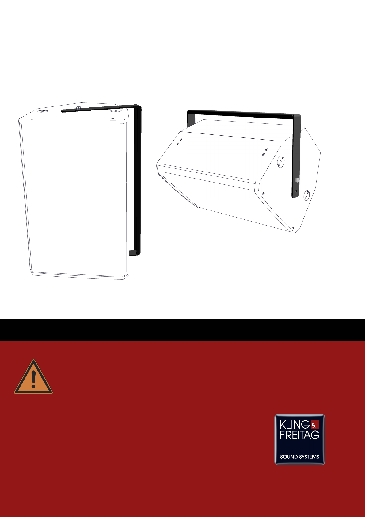
U-Mounts for CA
CA 1201
CACA
Loudspeakers with CA
Option 'Installation' CA
CA 1215
CACA
CA 1515
CACA
User’s Manual
Released: 01.06.2007
Version 1.0
Important Information,
Please Read Before Use!
KLING & FREITAG GmbH
Junkersstrasse 14
D-30179 Hannover
PHONE 0 (049) 511- 969 97-0
FAX 0 (049) 511- 67 37 94
www.klin
g-freitag.de
Page 2

User’s Manual U-Mount for CA 1201 / CA 1215 and CA1515 with option 'Installation'
KLING & FREITAG GMBH ©2003-2007 Version 1.0, 01.06.2007 Page 2 of 9
Page 3
User’s Manual U-Mount for CA 1201 / CA 1215 and CA1515 with option 'Installation'
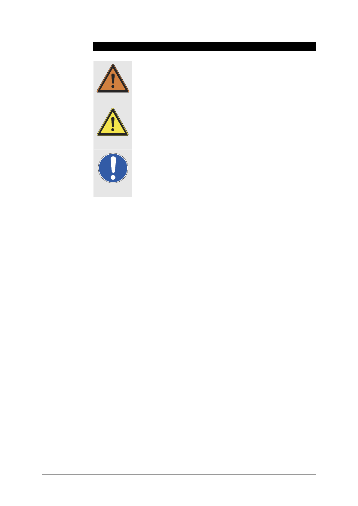
Symbols in User’s Manual
This symbol indicates the possibility of life-threatening danger and a
health risk for persons. Not following these instructions may result in
serious health problems including potentially fatal injuries.
Warning
Caution
Important
This symbol indicates a possibly dangerous situation. Not following
these instructions may cause minor injuries or cause property damage.
This symbol gives instructions for the proper use of the described products. Not following these instructions may cause malfunctions or property damage.
U-Mount for CA 1201 / CA 1215 and CA1515 with option 'Installation
',
Version 1.0, 01.06.2007
© by André Figula, Kling & Freitag GmbH, 2005; all rights reserved.
All specifications in this manual are based on information available at the time of pub-
lishing for the features and safety guidelines of the described products.
Technical specifications, measurements, weights and properties are not guaranteed.
The manufacturer reserves the right to make product alterations within legal provi-
sions as well as changes to improve product quality.
All persons who use this rig
All persons who use this rigging and mounting system must have this guide and all
All persons who use this rigAll persons who use this rig
further information for safe operations available to them during assembly, disa
further information for safe operations available to them during assembly, disas-
further information for safe operations available to them during assembly, disafurther information for safe operations available to them during assembly, disa
sembly, and use.
sembly, and use.
sembly, and use.sembly, and use.
ging and mounting system must have this guide and all
ging and mounting system must have this guide and all ging and mounting system must have this guide and all
s-
s-s-
We appreciate any input with suggestions and improvements for this manual. Please
send this to us at the following address:
info@kling-freitag.de
or to:
KLING & FREITAG GMBH, Junkersstr.14, D-30179 Hannover,
Phone +49 (0) 511 - 96 99 70 Fax +49 (0) 511 - 67 37 94
KLING & FREITAG GMBH ©2007 Version 1.0, 01.06.2007 Page 3 of 9
Page 4

User’s Manual U-Mount for CA 1201 / CA 1215 and CA1515 with option 'Installation'
Contents
Chapter Page
1. Safety Instructions 5
Shipped Components and Part Definitions 7
2.
3. Installation and Usage Instructions 8
4. Instructions for Ceiling and Wall Installation 9
5. Basic Dimensions, Weights and Load Capacity 9
5.1 U-Mount CA 1201 / CA 1215 with Option 'Installation' 9
5.2 U-Mount CA 1515 with Option 'Installation' 9
KLING & FREITAG GMBH ©2003-2007 Version 1.0, 01.06.2007 Page 4 of 9
Page 5

User’s Manual U-Mount for CA 1201 / CA 1215 and CA1515 with option 'Installation'
1. Safety Instructions
The rigging and mounting system may only be su
Warning
The rigging and mounting system may only be susssspended by trained specialised
The rigging and mounting system may only be suThe rigging and mounting system may only be su
personnel with proof of their qualific
personnel with proof of their qualificaaaations.
personnel with proof of their qualificpersonnel with proof of their qualific
The U-mount for Loudspeakers with Option ’Installation’ is only for professional use and is
only to be used to mount Kling & Freitag speakers CA 1201, CA 1215 und CA1515 with
their respective option ’Installation’ . Furthermore, it may only be used as specified for
uses at trade fairs, in theatres, studios, and events, etc. according to the stipulations
of the BGV C1 or a comparable national standard.
As a general rule the rigging and mounting system must be inspected each time it is
packed or unpacked. If permanently installed the system must be checked for signs of
wear at regular intervals.
In addition an inspection book for the rigging and mounting system should be kept.
This book should document maintenance measures and inspection intervals and contain parts lists.
If as a result of these checks any uncertainty should arise with regard to safety or if
specific faults are found, the rigging and mounting system may no longer be used.
During the course of these checks particular attention should be paid to evidence of
deformation, cracks, damage to threads and corrosion. Mounting devices such as
shackles, chains and wire ropes should also be carefully checked for signs of wear or
deformation.
Any damaged components must be replaced immediately. Do not attempt to repair
the U-mount by yourself! If the rigging and mounting system is damaged, it must be
disposed of immediately. Please send the adjustable speaker mount / U-mount back to
Kling & Freitag GmbH or bring it to a professional scrap processing plant. It must by
all means be guaranteed that the system can no longer be used in any way after its
disposal.
For assembly only original Kling & Freitag parts may be used. The use of other parts --in particular parts by other manufacturers --- is not authorized.
Please adhere to the maximum admissible load capacity labelled on the U-Mount and
do not exceed the maximum admissible configurations (1 loudspeaker system incl.
mounting accessories on one U-mount).
The U-mount may not be used to lift and secure persons or objects aside from the
above-mentioned speakers.
Please refer also to the operating and safety instructions for the product on which the
adjustable speaker mount is to be suspended (e.g. truss). If no information is available
regarding safety of use and permissible load, then the rigging and mounting system
must not be suspended upon it. Make sure that the rigging points on the ceiling of
the hall (i.e. chain hoists) comply with the accident prevention regulation BGV C1
(presentation and production sites for scenic performances) or the comparable safety
regulations for your country. Furthermore, the total load must be approved by TÜV or
a comparable institution. If in doubt, let local authorities verify this.
Those persons entrusted with the task of erecting the rigging system are responsible
for ensuring the safe assembly and safe operation of the system.
These instructions and all other necessary information regarding safety of operation
must be distributed to all persons using the rigging and mounting system. The system
may not be assembled and put into operation unless these instructions have been
read and understood.
When chain hoists are being used to lift loudspeakers all persons must vacate the area
below and around.
Only those persons directly involved in the assembly and dismantling procedures may
be present while work is in progress. A clear signal must be given on each occasion
before the system is raised, lowered or released from its rigging. All persons must
then remove themselves from the radius of movement.
tions.
tions.tions.
pended by trained specialised
pended by trained specialised pended by trained specialised
KLING & FREITAG GMBH ©2007 Version 1.0, 01.06.2007 Page 5 of 9
Page 6

User’s Manual U-Mount for CA 1201 / CA 1215 and CA1515 with option 'Installation'
The safe operation of the rigging and mounting system depends upon various factors
specific to the area of operation. For example, adverse weather conditions such as
wind or rain can impair the safety of the system. These factors must be considered
and evaluated in each case.
If there is the slightest d
If there is the slightest doubt with regard to the safety of the rigging and moun
If there is the slightest dIf there is the slightest d
ing system it may not be put into use.
ing system it may not be put into use.
ing system it may not be put into use.ing system it may not be put into use.
Ensure that all connections are secured against coming loose and that only author-
ized, statically tested and correctly sized supports, mounting equipment, wire ropes
and chains are used.
Observe the prescribed safety factors. Follow the safety instructions for speakers and
mounting equipment as well as the respective national rules, norms and safety regulations.
The information given here does not exempt the user from his obligation to observe
valid safety regulations and legal requirements.
oubt with regard to the safety of the rigging and mount-
oubt with regard to the safety of the rigging and mounoubt with regard to the safety of the rigging and moun
t-
t-t-
Warning
KLING & FREITAG GMBH ©2003-2007 Version 1.0, 01.06.2007 Page 6 of 9
Page 7

User’s Manual U-Mount for CA 1201 / CA 1215 and CA1515 with option 'Installation'
2. Shipped Components and Part Definitions
Friction gasket
5 x drill hole Ø 10.5 mm
Bracket
Side piece
2 x washer M 10
2 x bolt
M10 x 25
2 x lock washer M 10
KLING & FREITAG GMBH ©2007 Version 1.0, 01.06.2007 Page 7 of 9
Page 8

User’s Manual U-Mount for CA 1201 / CA 1215 and CA1515 with option 'Installation'
3. Installation and Usage Instructions
− Fasten U-mount to speaker using bolts M10 x 25 incl. washers and lock washers as
shown in illustration. Do not tighten the bolts all the way for the time being.
− Adjust the speaker as desired.
− Tighten the bolts.
− Always secure all screwed connections so that they cannot loosen on their own.
Washer
Drill hole A
Drill hole B
Drill hole B
Drill hole C
Drill hole D
Drill hole A
Bolt
M10 x 25
Lock washer
− Instructions for Ceiling and Wall Installation!
When mounting directly on
the wall or
ceiling, use at
lease both drill
holes A
holes A. Fol-
holes Aholes A
low instruc-
natively be used to mount the bracket to the speaker:
drill
drill drill
− A stand adapter can be mounted at the drill holes B
and nuts. Always secure all screwed connections so that they
cannot loosen on their own.
− A TV spigot 20 mm can be attached to drill hole C
using a self-locking nuts incl. a washer.
If there is not much space (i.e. low ceilings), the drill holes D
Drill hole E
drill holes B using bolts
drill holes Bdrill holes B
drill hole C of the bracket
drill hole Cdrill hole C
drill holes D can alter-
drill holes Ddrill holes D
Warning
Drill hole D
KLING & FREITAG GMBH ©2003-2007 Version 1.0, 01.06.2007 Page 8 of 9
Page 9

User’s Manual U-Mount for CA 1201 / CA 1215 and CA1515 with option 'Installation'
4. Instructions for Ceiling and Wall Installation
Before carrying through ceiling and wall installations, it is essential to consider the load
capacity of walls, ceilings and panelling as well as the stability and type of the construction. If there is wall panelling, for example, it is then necessary to examine the solidity of
Warning
the wall and use the appropriate wall plugs.
When installing on ceilings and walls, only the mounting drill holes which are specified
in the manual may be used.
Make sure to comply with the stipulated tightening torques.
5. Basic Dimensions, Weights and Load Capacity
5.1 U-Mount CA 1201 / CA 1215 with Option 'Installation'
116 mm
[4.567"]
310 mm
[12.205"]
620 mm
[24.409"]
5 x Ø10.5 mm
[5 x Ø0.413"]
20 mm
[0.787"]
336 mm
[13.228"]
5 mm
[0.197"]
Safe Working Load
Safe Working Load (SWL): 39
Safe Working LoadSafe Working Load
311 mm
[12.244"]
264 mm
[10.394"]
Weight
Weight:
WeightWeight
5.2 U-Mount CA 1515 with Option 'Installation'
20 mm
[0.787"]
338 mm
[13.307"]
[10.472"]
313 mm
[12.323"]
266 mm
24 mm
[0.945"]
48 mm
[1.890"]
: 3,05 kg
3,05 kg
: :
3,05 kg3,05 kg
(SWL): 39 kg
(SWL): 39 (SWL): 39
kg
kg kg
2 x Ø10.5 mm
[2 x Ø0.413"]
2 x Ø10.5 mm
[2 x Ø0.413"]
24 mm
5 mm
[0.197"]
5 x Ø10.5 mm
[5 x Ø0.413"]
116 mm
[4.567"]
347.5 mm
[13.681"]
695 mm
[27.362"]
Safe Working Load
Safe Working Load (SWL): 34
Safe Working LoadSafe Working Load
[0.945"]
48 mm
[1.890"]
Weight
Weight:
WeightWeight
: 3,30 kg
3,30 kg
: :
3,30 kg3,30 kg
(SWL): 34 kg
(SWL): 34 (SWL): 34
kg
kg kg
KLING & FREITAG GMBH ©2007 Version 1.0, 01.06.2007 Page 9 of 9
 Loading...