

Page 1
Operating Instructions
T r a n s l a t io n of t he or i g i n a l i ns tr uc ti on
Important Information,
Please Read Before Use!
KLING & FREITAG GmbH
Junkersstrasse 14
D-30179 Hannover
TEL +49 (0) 511- 969 97-0
FAX +49 (0) 511- 67 37 94
www.kling-freitag.de
Version 6.3
Released: 6.12.2016
K&F ACCESS Controller P.A. im ‚True Array Design‘
Page 2
Operating Instructions ACCESS SYSTEM
KLING & FREITAG GMBH ©1995-2016 Version 6.2, 06.12.2016 Page 2 of 2
ACCESS SYSTEM
Thank you for your decision to buy a KLING & FREITAG product. To guarantee a
trouble-free operating of the equipment and to enable the KLING & FREITAG
ACCESS System to achieve its full potential, please read the operating instructions carefully before use.
With the purchase of an ACCESS System, you have acquired a speaker system
with the highest possible quality and performance capabilities.
As the owner of this system, you now have a versatile and highly professional
tool which, when operated properly, is a true pleasure to use.
Symbols in User's Manual
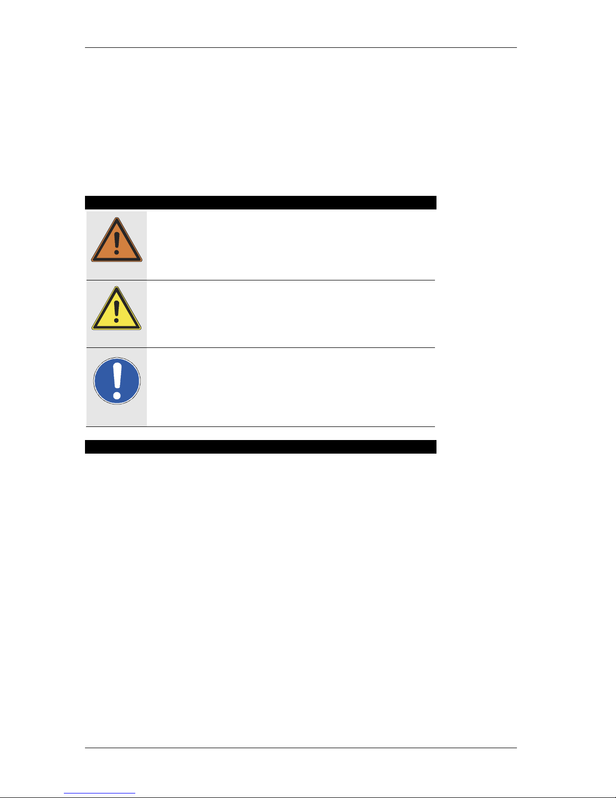
Warning
This symbol indicates the possibility of life-threatening danger and a
health risk for persons. Not following these instructions may result in
serious health problems including potentially fatal injuries.
Caution
This symbol indicates a possibly dangerous situation. Not following
these instructions may cause minor injuries or property damage.
Important
This symbol gives instructions for the proper use of the described products. Not following these instructions may cause malfunctions or property damage.
Information about this User's Manual
User's Manual ACCESS System Version 6.0, 06.12.2016
© by André Figula, Kling & Freitag GmbH, 1995 - 2016; all rights reserved.
All specifications in this manual are based on information available at the time of pub-
lishing for the features and safety guidelines of the described products.
Technical specifications, dimensions, weights and properties are not guaranteed.
The manufacturer reserves the right to make product alterations within legal provisions
as well as changes to improve product quality.
All persons who use the speaker system must have this guide and all further
information for safe operations available to them during assembly, disassembly, and use.
We appreciate any input with suggestions and improvements for this manual. Please
send this to us at the following address:
info@kling-freitag.de or to:
KLING & FREITAG GMBH Junkersstr.14 D-30179 Hannover
Phone +49 (0) 511 - 96 99 70 Fax +49 (0) 511 - 67 37 94
Page 3

Operating Instructions ACCESS SYSTEM
KLING & FREITAG GMBH ©1995-2016 Version 6.2, 06.12.2016 Page 3 of 3
Contents
Chapter Page
1. General Safety Instructions for Using Speakers
General Safety Instructions for Using SpeakersGeneral Safety Instructions for Using Speakers
General Safety Instructions for Using Speakers 5
2. The ACCESS System Components
The ACCESS System ComponentsThe ACCESS System Components
The ACCESS System Components 7
3. The Top Speakers
The Top SpeakersThe Top Speakers
The Top Speakers 9
3.1
3.13.1
3.1 T5 Mid/High System
T5 Mid/High SystemT5 Mid/High System
T5 Mid/High System 9
3.1.1 T5 Applications
T5 ApplicationsT5 Applications
T5 Applications 9999
3.1.2 T5 Technical Specifications
T5 Technical SpecificationsT5 Technical Specifications
T5 Technical Specifications 9999
3.1.3 T5 Measuring Charts
T5 Measuring ChartsT5 Measuring Charts
T5 Measuring Charts 10
1010
10
3.1.4 T5 Dimensions
T5 DimensionsT5 Dimensions
T5 Dimensions 10
1010
10
3.2
3.23.2
3.2 T9 Mid/High System
T9 Mid/High SystemT9 Mid/High System
T9 Mid/High System 11
3.2.1 T9 Applications
T9 ApplicationsT9 Applications
T9 Applications 11
1111
11
3.2.2 T9 Technical Specifications
T9 Technical SpecificationsT9 Technical Specifications
T9 Technical Specifications 11
1111
11
3.2.3 T9 Measuring Charts
T9 Measuring ChartsT9 Measuring Charts
T9 Measuring Charts 12
1212
12
3.2.4 T9 Dimensions
T9 DimensionsT9 Dimensions
T9 Dimensions 12
1212
12
4. The Subwoofers
The SubwoofersThe Subwoofers
The Subwoofers 13
4.1
4.14.1
4.1 Short
ShortShort
Short----Circuit Fuses in the K&F Subwoofer Sys
Circuit Fuses in the K&F Subwoofer SysCircuit Fuses in the K&F Subwoofer Sys
Circuit Fuses in the K&F Subwoofer Sys tems
temstems
tems 13
4.1.1 Risks of using High Performance Power Amplifiers
Risks of using High Performance Power AmplifiersRisks of using High Performance Power Amplifiers
Risks of using High Performance Power Amplifiers 13
1313
13
4.1.2 Identifying the Models with Short
Identifying the Models with ShortIdentifying the Models with Short
Identifying the Models with Short----Circuit Fuses
Circuit FusesCircuit Fuses
Circuit Fuses 13
1313
13
4.1.3 Add
AddAdd
Add----On Kits for Subwoofers without Short
On Kits for Subwoofers without ShortOn Kits for Subwoofers without Short
On Kits for Subwoofers without Short----Circuit
Circuit Circuit
Circuit Fuses
FusesFuses
Fuses 13
1313
13
4.1.4 Specification of the Fuses
Specification of the FusesSpecification of the Fuses
Specification of the Fuses 14
1414
14
4.1.5 Replacement and Positions of the Short
Replacement and Positions of the ShortReplacement and Positions of the Short
Replacement and Positions of the Short----Circuit Fuses
Circuit FusesCircuit Fuses
Circuit Fuses 14
1414
14
4.2
4.24.2
4.2 B5 Subwoofer System, Specifications
B5 Subwoofer System, SpecificationsB5 Subwoofer System, Specifications
B5 Subwoofer System, Specifications 15
4.2.1 B5 Applications
B5 ApplicationsB5 Applications
B5 Applications 15
1515
15
4.2.2 B5 Technical Specifications
B5 Technical SpecificationsB5 Technical Specifications
B5 Technical Specifications 15
1515
15
4.2.3 B5 Measuring Charts
B5 Measuring ChartsB5 Measuring Charts
B5 Measuring Charts 16
1616
16
4.2.4 B5 Dimensions
B5 DimensionsB5 Dimensions
B5 Dimensions 16
1616
16
4.3
4.34.3
4.3 B10 Subwoofer System
B10 Subwoofer SystemB10 Subwoofer System
B10 Subwoofer System 17
4.3.1 B10 Applications
B10 ApplicationsB10 Applications
B10 Applications 17
1717
17
4.3.2 B10 Technical Specifications
B10 Technical SpecificationsB10 Technical Specifications
B10 Technical Specifications 17
1717
17
4.3.3 B10 Measuring Charts
B10 Measuring ChartsB10 Measuring Charts
B10 Measuring Charts 18
1818
18
4.3.4 B10 Dimensions
B10 DimensionsB10 Dimensions
B10 Dimensions 18
1818
18
4.4
4.44.4
4.4 Using the ACCES
Using the ACCESUsing the ACCES
Using the ACCESS B5 / B10 with other K&F Systems
S B5 / B10 with other K&F SystemsS B5 / B10 with other K&F Systems
S B5 / B10 with other K&F Systems 19
5. Pin Diagrams of Connectors and internal Wiring
Pin Diagrams of Connectors and internal WiringPin Diagrams of Connectors and internal Wiring
Pin Diagrams of Connectors and internal Wiring 19
5.1
5.15.1
5.1 ACCESS T5 Pin Diagrams of Connectors and Wiring
ACCESS T5 Pin Diagrams of Connectors and WiringACCESS T5 Pin Diagrams of Connectors and Wiring
ACCESS T5 Pin Diagrams of Connectors and Wiring 19
5.2
5.25.2
5.2 ACCESS T9 Pin Diagrams of Con
ACCESS T9 Pin Diagrams of ConACCESS T9 Pin Diagrams of Con
ACCESS T9 Pin Diagrams of Connectors and Wiring
nectors and Wiringnectors and Wiring
nectors and Wiring 19
5.3
5.35.3
5.3 ACCESS B5 Pin Diagrams of Connectors
ACCESS B5 Pin Diagrams of ConnectorsACCESS B5 Pin Diagrams of Connectors
ACCESS B5 Pin Diagrams of Connectors 20
5.4
5.45.4
5.4 ACCESS B10 Pin Diagrams of Connectors
ACCESS B10 Pin Diagrams of ConnectorsACCESS B10 Pin Diagrams of Connectors
ACCESS B10 Pin Diagrams of Connectors 20
6. Safety Instructions for Controller and Connector Panel
Safety Instructions for Controller and Connector PanelSafety Instructions for Controller and Connector Panel
Safety Instructions for Controller and Connector Panel 21
7. K&F CD 44 Digital System Controller
K&F CD 44 Digital System ControllerK&F CD 44 Digital System Controller
K&F CD 44 Digital System Controller 22
8. The ACCESS Controllers
The ACCESS ControllersThe ACCESS Controllers
The ACCESS Controllers 22
8.1
8.18.1
8.1 The ACCESS C5/9 Controller
The ACCESS C5/9 ControllerThe ACCESS C5/9 Controller
The ACCESS C5/9 Controller 23
8.1.1 Connectors, Controls and Displays and of the C5/9
Connectors, Controls and Displays and of the C5/9Connectors, Controls and Displays and of the C5/9
Connectors, Controls and Displays and of the C5/9 23
2323
23
Page 4

Operating Instructions ACCESS SYSTEM
KLING & FREITAG GMBH ©1995-2016 Version 6.2, 06.12.2016 Page 4 of 4
8.1.2 C5/9 Controller Technical Specifications
C5/9 Controller Technical SpecificationsC5/9 Controller Technical Specifications
C5/9 Controller Technical Specifications 25
2525
25
8.1.3 Pin Diagrams of the C5/9 Controller's In
Pin Diagrams of the C5/9 Controller's InPin Diagrams of the C5/9 Controller's In
Pin Diagrams of the C5/9 Controller's In---- and Outputs
and Outputsand Outputs
and Outputs 25
2525
25
8.2
8.28.2
8.2 The ACCE
The ACCEThe ACCE
The ACCESS C10 Controller
SS C10 ControllerSS C10 Controller
SS C10 Controller 26
8.2.1 Connectors, Controls and Displays and of the C10
Connectors, Controls and Displays and of the C10Connectors, Controls and Displays and of the C10
Connectors, Controls and Displays and of the C10 26
2626
26
8.2.2 C10 Controller Technical Specifications
C10 Controller Technical SpecificationsC10 Controller Technical Specifications
C10 Controller Technical Specifications 29
2929
29
8.2.3 Pin Diagrams C10 Controller In
Pin Diagrams C10 Controller InPin Diagrams C10 Controller In
Pin Diagrams C10 Controller In---- and Outputs
and Outputsand Outputs
and Outputs 29
2929
29
9. The ACCESS Connector Panels
The ACCESS Connector PanelsThe ACCESS Connector Panels
The ACCESS Connector Panels 30
9.1
9.19.1
9.1 Connectors of the Connector Panels CP1 and CP3
Connectors of the Connector Panels CP1 and CP3Connectors of the Connector Panels CP1 and CP3
Connectors of the Connector Panels CP1 and CP3 30
9.1.1 Connector Panel CP1 und CP3 Technical Specifications
Connector Panel CP1 und CP3 Technical SpecificationsConnector Panel CP1 und CP3 Technical Specifications
Connector Panel CP1 und CP3 Technical Specifications 31
3131
31
9.1.2 CP1 and CP3 Pin Diagrams of In
CP1 and CP3 Pin Diagrams of InCP1 and CP3 Pin Diagrams of In
CP1 and CP3 Pin Diagrams of In---- and Outputs
and Outputsand Outputs
and Outputs 32
3232
32
9.2
9.29.2
9.2 Connectors of the Bass Connector Panels CP1
Connectors of the Bass Connector Panels CP1Connectors of the Bass Connector Panels CP1
Connectors of the Bass Connector Panels CP1----B und CP3
B und CP3B und CP3
B und CP3----BBBB 33
9.2.1 Connector Panel CP1
Connector Panel CP1Connector Panel CP1
Connector Panel CP1----B und CP3
B und CP3B und CP3
B und CP3----B Technical Specifications
B Technical SpecificationsB Technical Specifications
B Technical Specifications 34
3434
34
9.2.2 CP1
CP1CP1
CP1----B and CP3
B and CP3B and CP3
B and CP3----B Pin Diagrams of In
B Pin Diagrams of InB Pin Diagrams of In
B Pin Diagrams of In---- and Outputs
and Outputsand Outputs
and Outputs 35
3535
35
10. Connecting Instructions for the ACCESS System
Connecting Instructions for the ACCESS SystemConnecting Instructions for the ACCESS System
Connecting Instructions for the ACCESS System 36
10.1
10.110.1
10.1 Wiring
WiringWiring
Wiring 36
10.2
10.210.2
10.2 Avoiding Ground Loops
Avoiding Ground LoopsAvoiding Ground Loops
Avoiding Ground Loops 37
10.2.1 What is a Ground Loop?
What is a Ground Loop?What is a Ground Loop?
What is a Ground Loop? 37
3737
37
10.2.2 Avoiding Ground Loops
Avoiding Ground LoopsAvoiding Ground Loops
Avoiding Ground Loops 37
3737
37
11. Recommended Amplifier Performance for the ACCESS System
Recommended Amplifier Performance for the ACCESS SystemRecommended Amplifier Performance for the ACCESS System
Recommended Amplifier Performance for the ACCESS System 38
11.1
11.111.1
11.1 Correct Bass and Top Speaker Ratio
Correct Bass and Top Speaker RatioCorrect Bass and Top Speaker Ratio
Correct Bass and Top Speaker Ratio 39
12. Mounting Instructions for Loudspeakers
Mounting Instructions for LoudspeakersMounting Instructions for Loudspeakers
Mounting Instructions for Loudspeakers 40
12.1
12.112.1
12.1 Mounting and Stacking the ACCESS Systems
Mounting and Stacking the ACCESS SystemsMounting and Stacking the ACCESS Systems
Mounting and Stacking the ACCESS Systems 41
12.2
12.212.2
12.2 Using the MAN Rigging Points
Using the MAN Rigging PointsUsing the MAN Rigging Points
Using the MAN Rigging Points 42
13. Operating the
Operating the Operating the
Operating the ACCESS SYSTEM
ACCESS SYSTEMACCESS SYSTEM
ACCESS SYSTEM 43
14. Connection Diagrams
Connection DiagramsConnection Diagrams
Connection Diagrams 44
14.1
14.114.1
14.1 ACCESS System with Controller C5/9 and CP1/3
ACCESS System with Controller C5/9 and CP1/3ACCESS System with Controller C5/9 and CP1/3
ACCESS System with Controller C5/9 and CP1/3 44
14.2
14.214.2
14.2 ACCESS System with Controller C5/9, no Connector Panel
ACCESS System with Controller C5/9, no Connector PanelACCESS System with Controller C5/9, no Connector Panel
ACCESS System with Controller C5/9, no Connector Panel 45
14.3
14.314.3
14.3 Optimised Operations with B10, C10 and CP1/3
Optimised Operations with B10, C10 and CP1/3Optimised Operations with B10, C10 and CP1/3
Optimised Operations with B10, C10 and CP1/3----BBBB 46
14.4
14.414.4
14.4 Optimised Operations with B10, C10 without CP1/3
Optimised Operations with B10, C10 without CP1/3Optimised Operations with B10, C10 without CP1/3
Optimised Operations with B10, C10 without CP1/3----BBBB 47
15. Sound Pressure Dispersion of Mid
Sound Pressure Dispersion of MidSound Pressure Dispersion of Mid
Sound Pressure Dispersion of Mid----High Systems T5 & T9
High Systems T5 & T9High Systems T5 & T9
High Systems T5 & T9 48
15.1
15.115.1
15.1 Sound Pressure Dispersion of combined Mid
Sound Pressure Dispersion of combined MidSound Pressure Dispersion of combined Mid
Sound Pressure Dispersion of combined Mid----High Systems
High SystemsHigh Systems
High Systems 49
15.2
15.215.2
15.2 Sound Pressure Dispersion in Relation to the Position
Sound Pressure Dispersion in Relation to the PositionSound Pressure Dispersion in Relation to the Position
Sound Pressure Dispersion in Relation to the Position 50
16. Basic Rules for the Alignment of the ACCESS Systems
Basic Rules for the Alignment of the ACCESS SystemsBasic Rules for the Alignment of the ACCESS Systems
Basic Rules for the Alignment of the ACCESS Systems 51
17. Examples of Configurations and Applications
Examples of Configurations and ApplicationsExamples of Configurations and Applications
Examples of Configurations and Applications 53
18. Accessories for the ACCESS System
Accessories for the ACCESS SystemAccessories for the ACCESS System
Accessories for the ACCESS System 58
19. Regulations for Disposal
Regulations for DisposalRegulations for Disposal
Regulations for Disposal 60
19.1
19.119.1
19.1 Germany:
Germany:Germany:
Germany: 60
19.2
19.219.2
19.2 EU, Norway, Island, and Liechtenstein (not Germany):
EU, Norway, Island, and Liechtenstein (not Germany):EU, Norway, Island, and Liechtenstein (not Germany):
EU, Norway, Island, and Liechtenstein (not Germany): 60
19.3
19.319.3
19.3 Other countries
Other countriesOther countries
Other countries 60
20. Included Safety and Mounting Instructions for Loudspeakers and Accessories
Page 5
Operating Instructions ACCESS SYSTEM
KLING & FREITAG GMBH ©1995-2016 Version 6.2, 06.12.2016 Page 5 of 5
1. General Safety Instructions for Using Speakers
Mounting the speakers
To prevent injury or property damage, this equipment must be securely placed on the floor
or mounted in a different manner according to the mounting instructions on page 40
(Mounting Instructions for Loudspeakers). Speakers, which are stacked, must be secured
with safety straps. Please note that speakers can move as a result of vibrations. To prevent them from falling from their mounted position, they must be secured properly.
If the weight of the speaker exceeds 20 kg then it is necessary for two people to carry it.
Speakers may only be mounted to walls and ceilings by qualified personnel. The speakers must be hung by using the two designated MAN flying points on the sides of the
speaker. The same applies when lifting and aligning the speakers. Only connections
designed to fit the flying points should be used. If in doubt, please consult the manufacturer.
The bass system ACCESS B10 is not designed for flown applications.
Never use signal cables or power cords for suspending, aligning or securing the systems.
When laying the connecting cables, make sure that nobody can trip.
Never hang more than two speakers under one another without using the designated
Kling & Freitag rigging equipment.
Ensure that all installation connections comply with the applicable safety guidelines and
that the size and strength are sufficient. Further instructions are in our user's manual for
assembly equipment and in the general safety instructions for speakers and accessories.
For mobile and fixed installations, use only mounting accessories from Kling & Freitag, if
possible.
Speakers and mounting accessories must be visually examined at regular intervals. If
there are signs of wear, they must be replaced immediately. Furthermore, screwed connections of supporting parts must be checked routinely.
Protecting the speakers / avoiding fire hazard
In general, audio signals should not be overdriven. This may be caused by mixing consoles,
equalizers, effect equipment, etc. and should be indicated on this equipment. When a power
amplifier is overloaded at the output (clipping), then the amplifier should activate a clipping
warning signal. Power amplifiers can also be overloaded at the input circuit without the
amplifier signalling the clipping, i.e. when there is not sufficient headroom in the input circuit. We, therefore, recommend turning up the power amplifiers all the way and adjusting
the level before the power amplifier in order to avoid overloading the input circuit. In any
case, the signal must be reduced as soon as it sounds unnaturally distorted.
− To protect the speakers from being destroyed and to avoid fire hazard, they should
only be operated with professional power amplifiers with the following specifications:
− Amplification according to the instructions in the chapter Recommended Amplifier
Performance for the ACCESS System from page 38 onwards.
− Integrated clipping limiter
− without using a Kling & Freitag controller (not recommended):
Integrated or preceding subsonic filter (approx. 20 Hz, min. 12 dB / octave)
Power amplifiers with power specifications lower than those stated from page
39 onwards must be supplied with a clip limiter for speaker protection, even if
they are operated with a Kling & Freitag system controller.
If you wish to use a speaker with a power amplifier that does not fulfil these specifications,
then the speaker should be controlled using a Kling & Freitag system controller with limiter
function. This is the only way overloading and the risk of fire can be avoided. The results of
such a power amplifier defect cannot be avoided by the controller.
For damage caused by overloading or use with power amplifiers other than those recommended above or with amplifiers with higher output power, Kling & Freitag GmbH
does not assume warranty and excludes liability for possible consequential damage.
Warning
Warning
Page 6
Operating Instructions ACCESS SYSTEM
KLING & FREITAG GMBH ©1995-2016 Version 6.2, 06.12.2016 Page 6 of 6
The following signals may damage the speakers
− permanent high-pitched signals with high frequency and continuous noise from
feedback.
− permanently distorted signals with high power.
− noises, which occur when the amplifier is on while equipment is being connected,
disconnected or switched on.
Do not install speakers in any of the following places:
− where the speakers are permanently exposed to direct sunlight
− where the speakers are exposed to high moisture or rain
− where the speakers are exposed to strong vibrations and dust.
Damage caused by the speakers' magnetic fields
Speakers are permanently surrounded by a magnetic field, even when they are not operating. Therefore, during transport and placement of the speakers, it is important to
ensure that there is always approx. 1 m between the speakers and magnetic data media
and computer/video monitors.
Preventing hearing damage
To prevent the risk of hearing damage, avoid being too close to operating speakers,
even if the volume level seems to be low enough. In general, volume levels over 90 dB
can cause hearing damage.
Important
Caution
Page 7
Operating Instructions ACCESS SYSTEM
KLING & FREITAG GMBH ©1995-2016 Version 6.2, 06.12.2016 Page 7 of 7
2. The ACCESS System Components
The ACCESS SYSTEM consists of the perfectly tuned system components including
speakers, system controllers and connector panels. This manual describes up through
and including chapter 8 each individual component. Subsequently, connecting instructions and system configurations are mentioned and explained based on example.
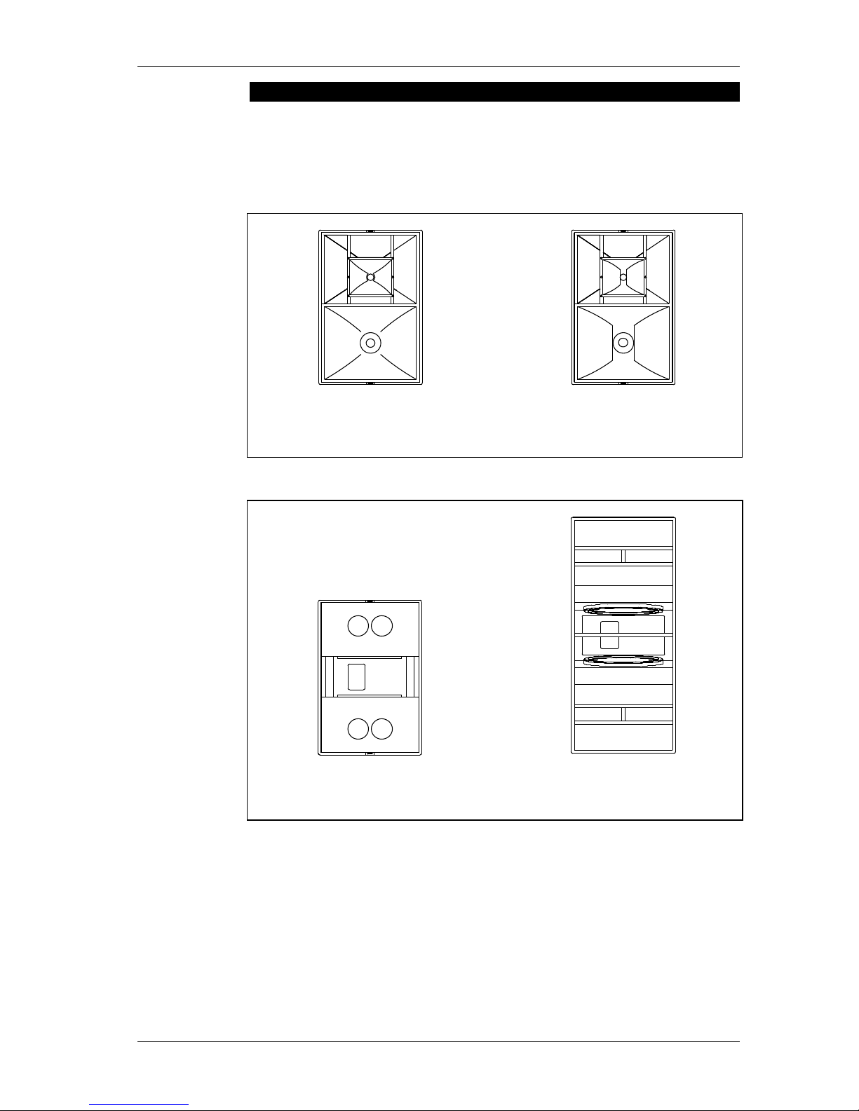
ACCESS Mid-High Systems:
ACCESS T5
Description as of page 9
ACCESS T9
Description as of page 11
ACCESS Bass Systems:
ACCESS B5
Description as of page 15
ACCESS B10
Description as of page 17
Page 8
Operating Instructions ACCESS SYSTEM
KLING & FREITAG GMBH ©1995-2016 Version 6.2, 06.12.2016 Page 8 of 8
ACCESS System Controller:
System Controller ACCESS C5/9
Description as of page 23
CLUSTER
SINGLE
8
HIGH BOOST
NORMAL
ACCES
S
C5/9
0
+6
LEVEL
CLIP
dB
SENSE (GREEN) / LIMIT (RED)
H
I
G
H
+
10
d
B
INPUT SIGNAL
-40
dB
0
dB
MID
E
XCURS
I
O
N
B
A
SS
O
N
POWER
ACCESS
SYSTEMCONTROLLER
System Controller ACCESS C10
Description as of page 26
CLUSTER
SINGLE
8
HIGH BOOST
NORMAL
ACCES
S
C5/9
0
+6
LEVEL
CLIP
dB
SENSE (GREEN) / LIMIT (RED)
H
I
G
H
+
10 d
B
INPUT SIGNAL
-40
d
B
0 dB
MIDE
XC
U
R
S
I
O
N
BASS
O
N
POWER
ACCESS
SYSTEMCONTROLLER
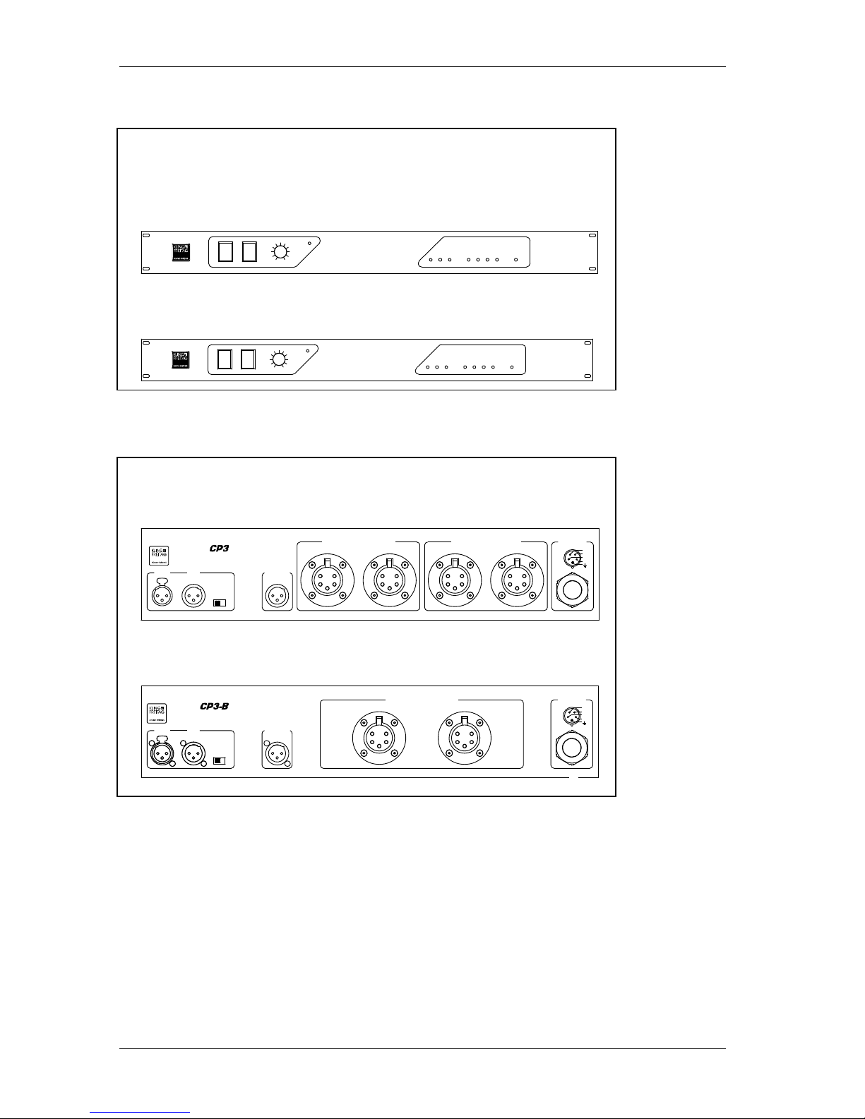
Connector Panels:
Connector Panel CP1 / CP3 for operations with the ACCESS C5/9 Controller.
Description as of page 30
3
BASS SPEAKER OUT
INPUT LINK BASS OUT
GROUND
ON OFF
TOP SPEAKER OUT MAINS
ACCES S
L 1
N
L 2
L 3
Connector Panel CP1-B / CP3-B for operations with the ACCESS C10 Controller
Description as of page 33
BASS SPEAKER OUT
231
NEUTRIK
PUSH
132
NEUTRIK
INPUT LINK BASS OUT
GROUND
ON OFF
MAINS
ACCESS
L 1
N
L 2
L 3
1
234
5
231
NEUTRIK
PUSH
132
NEUTRIK
132
NEUTRIK
1
234
5
Page 9

Operating Instructions ACCESS SYSTEM
KLING & FREITAG GMBH ©1995-2016 Version 6.2, 06.12.2016 Page 9 of 9
3. The Top Speakers
3.1 T5 Mid/High System
3.1.1 T5 Applications
The ACCESS T5 is a horn-loaded high-end sound system with a consistent and homogeneous dispersion pattern of 50° x 40°, and is, therefore, predestined for use in clusters and arrays. The areas of use range from discotheques and live sound coverage to
large events and mega open-airs. The T5 meets all demands at the highest level --- from
techno to classic. With wide-band highest sound pressure levels exceeding 140 dB and
an optimal audio quality, a minimum number of units is necessary. This allows for maximum efficiency for set-up and dismantling.
3.1.2 T5 Technical Specifications
Design 2-way horn loaded
Frequency response -10 dB 100 Hz - 20 kHz (with Controller C5/9)
Frequency response ± 3 dB 130 Hz - 19 kHz (with Controller C5/9)
Nominal coverage angle 50° x 40° (hor. x vert.)
Directivity index (DI) 14 (+1.5/-2) 630 Hz - 16 kHz
Nominal power handling 500 W low-mid, 120 watts mid-high
Sensitivity 1 W/1 m 110 dB low-mid, 113 dB mid-high
Max. SPL 143 dB (SPL peak/1 m)
Components 12" chassis with conical horn
5" compression driver with CD horn / 12‘‘ diaphragm
1.5" compression driver with CD horn / 3“ diaphragm
Crossover All-pass filter optimises phase response and delay time
between the 5’’ and 12’’ driver
Impedance
5Ω low-mid, 10Ω mid-high
Connectors EP-5 male / female MID: 1+ / 2-, HIGH: 3- / 4+
Enclosure Trapezoid with 2 cluster angles 4°/15°
15 mm birch plywood with highly resistant black
structured paint
4 ergonomic butterfly handles
4 100 mm transport castors mounted on the rear,
ball proof front grille with exchangeable black
acoustic foam
Rigging 2 MAN CF4T rigging points, 2 MAN HWKB strap
attachments for securing straps
Dimensions 600 x 900 x 750 mm without castors (W x H x D)
Weight incl. Castors 92 kg
Options Transport cover with butterfly catches,
MAN/K&F flying hardware, ATM modular cradle
system, special finish in RAL colours, All Weather /
Outdoor version
Page 10
Operating Instructions ACCESS SYSTEM
KLING & FREITAG GMBH ©1995-2016 Version 6.2, 06.12.2016 Page 10 of 10
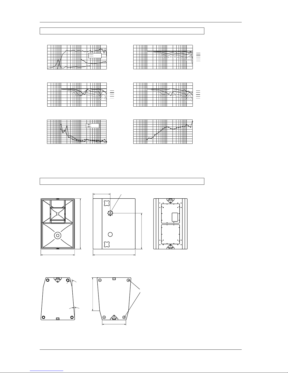
3.1.3 T5 Measuring Charts
Frequency response
“
on axis
“
with Controller C5/9
Q-Index
Beamwidth
Vertical frequency response “ off axis down “
Vertical frequency response “off axis up “
Horizontal frequency response
“
off axis
“
All m easur ement s: Far field c onditio ns. Fr equen cy reso nse 1 /6 octa ve ave raged , pola r and d irectiv ity dat a 1/3 octav e aver aged. Kling & Fre itag res erves the r ight to chan ge all specif icatio ns
with out no tice. W e are not lia ble fo r misp rints.
20 100 1000 10000 20000
-30
-20
-10
0
10
Attenuation (dB)
Frequency (Hz)
0°
10°
20°
30°
40°
100 1000 10000 20000
0°
10°
20°
30°
40°
Frequency (Hz)
20
-30
-20
-10
0
10
Attenuation (dB)
20
20 100 1000 10000 20000
1
10
100
Directivity Factor (Q)
Directivity Index (DI), dB
Frequency (Hz)
0
10
Frequency (Hz)
-10
0
10
Attenuation (dB)
100 1000 10000 20000
0°
10°
20°
30°
40°
20
-30
-20
20 100 1000 10000 20000
-30
0
Frequency(Hz)
dB
3,16
31,6
316
Impedance (Ohm)
100
-20
-10
10
10
Normal
HighBoost
20
-6dB Beamwidth (degr
ees)
100 1000 10000 20000
Frequency (Hz)
0
60
120
180
240
300
360
Horizontal
Vertical
3.1.4 T5 Dimensions
Front View
Top View
15°
4
600 mm
Bottom View
Sliders
Plastic
588 mm
MAN Flying Point CF4T
307 mm
Side View
900 mm
421 mm
750 mm
639 mm
Rear View
Page 11

Operating Instructions ACCESS SYSTEM
KLING & FREITAG GMBH ©1995-2016 Version 6.2, 06.12.2016 Page 11 of 11
3.2 T9 Mid/High System
3.2.1 T9 Applications
The ACCESS T5 is a horn-loaded high-end sound system with a consistent and homogeneous dispersion pattern of 90° x 40°. It is, therefore, extremely well suited for small
to medium coverage requirements with just one system per side such as live concerts in
clubs and sound coverage in discotheques. By using pair clusters with another T9 or
large arrays with the fully compatible T5, it is possible to use the equipment at large
events and mega open-air concerts. The T9 meets all demands at the highest level --from techno to classic. With wideband highest sound pressure up to 139 dB and an
optimal audio quality, a minimum number of units is necessary. This allows for maximum efficiency for set-up and dismantling.
3.2.2 T9 Technical Specifications
Design 2-way horn loaded
Frequency response -10 dB 100 Hz - 19 kHz (with Controller C5/9)
Frequency response ± 3 dB 130 Hz - 17 kHz (with Controller C5/9)
Nominal coverage angle 90° x 40° (hor. x vert.)
Directivity index (DI) 12 (+1.5/-1.5) 500 Hz - 20 kHz
Nominal power handling 500 watts low-mid, 120 watts mid-high
Sensitivity 1 W/1 m 108 dB low-mid, 110 dB mid-high
Max. SPL 139 dB (SPL peak/1 m)
Components 12" chassis with conical horn
5" compression driver with CD horn / 12‘‘ diaphragm
1.5" compression driver with CD horn / 3“ diaphragm
Crossover All-pass filter optimises phase response and delay
time between the 5’’ and 12’’ driver
Impedance
5Ω low-mid, 10Ω mid-high
Connectors EP-5 male / female MID: 1+ / 2-, HIGH: 3- / 4+
Enclosure Trapezoid with 2 cluster angles 4°/15°
15 mm birch plywood with highly resistant
black structured paint
4 ergonomic butterfly handles
4 100 mm transport castors mounted on the rear,
ball proof front grille with exchangeable black
acoustic foam
Rigging 2 MAN CF4T flying points, 2 MAN HWKB strap
attachments for securing straps
Dimensions 600 x 900 x 750 mm without castors (W x H x D)
Weight incl. Castors 92 kg
Options Transport cover with butterfly catches,
MAN/K&F flying hardware, ATM modular cradle
system, special finish in RAL colours, All Weather /
Outdoor version
Page 12
Operating Instructions ACCESS SYSTEM
KLING & FREITAG GMBH ©1995-2016 Version 6.2, 06.12.2016 Page 12 of 12
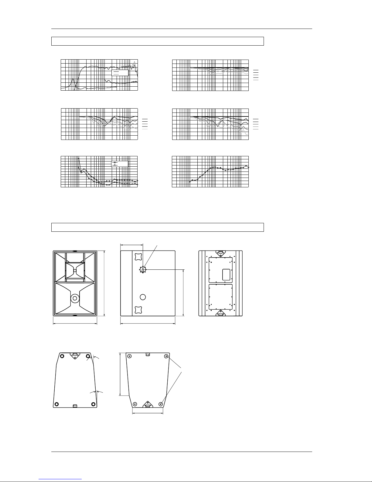
3.2.3 T9 Measuring Charts
Frequency response
“
on axis
“
with Controller C5/9
Q-Index
Beamwidth
Vertical frequency response “ off axis down “
Vertical frequency response “off axis up “
Horizontal frequency response
“
off axis
“
All m easur ement s: Far field c onditio ns. Fr equen cy reso nse 1/ 6 octa ve ave raged , pola r and d irectiv ity dat a 1/3 octav e aver aged. Kling & Fre itag res erves the ri ght to chan ge all specif ication s
with out no tice. W e are not lia ble fo r misp rints.
20 100 1000 10000 20000
-30
0
Frequency(Hz)
dB
3,16
31,6
316
Impedance (Ohm)
100
-20
-10
10
10
Normal
HiBoost
20 100 1000 10000 20000
-30
-20
-10
0
10
Attenuation (dB)
Frequency (Hz)
0°
10°
20°
30°
40°
-10
0
10
Attenuation (dB)
100 1000 10000 20000
0°
10°
20°
30°
40°
Frequency (Hz)
20
-30
-20
100 1000 10000 20000
0°
10°
20°
30°
40°
Frequency (Hz)
20
-30
-20
-10
0
10
Attenuation (dB)
20
20 100 1000 10000 20000
1
10
100
Directivity Factor (Q)
Directivity Index (DI), dB
Frequency (Hz)
0
10
20
-6dB Beamwidth (degr
ees)
100 1000 10000 20000
Frequency (Hz)
0
60
120
180
240
300
360
Horizontal
Vertical
3.2.4 T9 Dimensions
15°
4°
600 mm
588 mm
307 mm
900 mm
421 mm
750 mm
639 mm
Front View
Top View Bottom View
Sliders
Plastic
MAN Flying Point CF4T
Side View
Rear View
Page 13
Operating Instructions ACCESS SYSTEM
KLING & FREITAG GMBH ©1995-2016 Version 6.2, 06.12.2016 Page 13 of 13
4. The Subwoofers
4.1 Short-Circuit Fuses in the K&F Subwoofer Systems
4.1.1 Risks of using High Performance Power Amplifiers
In recent years, power amplifiers have achieved increasingly higher levels of performance. Some of them can be operated with low-impedance loads. There are, therefore,
strong power amplifiers that can reliably work with impedances below 1 Ω. This development has led to an increased safety risk during defective operations.
When there is a defect, such as a short circuit in the speaker chassis or on the crossover,
it is possible that the power amplifier --- despite existing protective switches --- will not
shut off. Long cable lengths and contact resistance on the plug connections may already
have an electrical resistance of 1 Ω. As a result, the power amplifier cannot ‘‘recognise’’
the operations as being defective and, therefore, delivers unacceptable high currents. In
the worst-case scenario, this may lead to fire damage (hot and charred wiring / connectors as a result of overloaded wires and connectors, etc.).
The current safety regulations are lagging behind this development and are thus not up-to-date with this modern
technology.
Normally, the K&F System Controller prevents the speaker from being overloaded. The results of such a defect cannot be avoided by the controller.
In order to give consideration to this development, Kling & Freitag now equips its subwoofer systems with short circuit fuses at the signal input. These fuses do not offer
protection for the speaker, but do reduce the risk of consequential damage in the case
of a short circuit.
For systems, which are not serially equipped with a short circuit fuse, Kling & Freitag
offers simple add-on kits so that you can adapt your existing subwoofer systems to the
current power amplifier development.
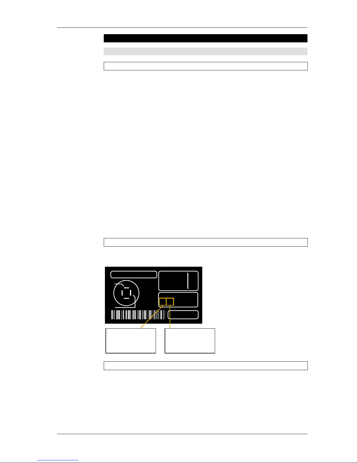
4.1.2 Identifying the Models with Short-Circuit Fuses
The subwoofer systems, which are serially equipped with short-circuit fuses can be identified as follows; both mentioned stipulations must be fulfilled:
4.1.3 Add-On Kits for Subwoofers without Short-Circuit Fuses
All subwoofer systems, which are not serially equipped with short circuit fuses, can be, if
required, easily and inexpensively upgraded even by yourself.
An instruction manual for this upgrade is delivered with the add-on kit.
POWER: 700W
WT:
51,5kg
XO-ONOFF
SER.-NO.:
25080000070
IMP: 6
Ω8Ω
Zmin:
4
Ω
6
Ω
-
1
-
2
-
1+
2+
+
IN
all pins
parallel
to out
The first two
digits must be at
least 25.
The next two
digits must be at
least 08.
Page 14

Operating Instructions ACCESS SYSTEM
KLING & FREITAG GMBH ©1995-2016 Version 6.2, 06.12.2016 Page 14 of 14
4.1.4 Specification of the Fuses
The fuses in all models have the following identical specifications:
Bussmann S 506
Bussmann S 506Bussmann S 506
Bussmann S 506----8A slow
8A slow8A slow
8A slow
When necessary, these fuses may only be replaced with the aforementioned original fuse.
4.1.5 Replacement and Positions of the Short-Circuit Fuses
When the fuse is blown, then the chassis is most likely already ruined, as the fuse just
prevents consequential damage resulting from a short circuit of the chassis.
A disassembly of the chassis is, therefore, unavoidable.
The fuse holder of the subwoofers is mounted on the signal wiring behind the input
connector. The ACCESS subwoofers have 2 fuses; one for each of the parallel operating
chassis.
When replacing the fuse, the lid of the terminal with the signal connectors must be
screwed off to reach the fuse holder.
Warning
Page 15

Operating Instructions ACCESS SYSTEM
KLING & FREITAG GMBH ©1995-2016 Version 6.2, 06.12.2016 Page 15 of 15
4.2 B5 Subwoofer System, Specifications
4.2.1 B5 Applications
The ACCESS B5 is a high-performance subwoofer system of the ACCESS Series. It is
fully compatible with all existing Kling & Freitag speaker products and shows off all its
qualities here too. Because of its high efficiency and technical perfection, the B5 is used
in the high quality service segment, at discotheques and live sound coverage as well as
venues with fixed installations such as theatres and multimedia facilities. When used in
arrays with the optimally matched top speakers T5 and T9, the possibilities of use expand to include large events and mega open airs. The T9 meets all demands at the
highest level --- from hard rock to classic.
4.2.2 B5 Technical Specifications
Design 3 chamber band pass, 6th order
Frequency response -10 dB 34 Hz - 400 Hz
Frequency response ± 3 dB 45 Hz - 190 Hz
Crossover frequencies max. 180 Hz, 130 Hz with controller C5/9
Nominal power handling 1200 W
Sensitivity 1 W/1 m 101 dB (45 Hz - 200 Hz)
Max SPL 136 dB (SPL peak/1 m)
Components 18" long excursion transducers (2)
Impedance
1 x 4 Ω
With option 'EP-5 instead of Speakon': 2 x 8 Ω
Connectors Sp.1: 2- / 3+-, Sp.2: 1- / 4+
Enclosure Trapezoid with 2 cluster angles 4°/15°
15 mm birch plywood with highly resistant
black structured paint
4 ergonomic butterfly handles
4 100 mm transport castors mounted on the rear,
ball proof front grille with exchangeable black
acoustic foam
Rigging 2 MAN CF4T flying points, 2 MAN HWKB strap
attachments for securing straps
Dimensions 600 x 900 x 750 mm without castors (W x H x D)
Weight incl. castors 82 kg
Options Transport cover with butterfly catches,
special finish in RAL colours, All Weather /
Outdoor version
Page 16
Operating Instructions ACCESS SYSTEM
KLING & FREITAG GMBH ©1995-2016 Version 6.2, 06.12.2016 Page 16 of 16
4.2.3 B5 Measuring Charts
Fr
equenzgang
“
on axis
“
Fr
equenzgang
“
on axis
“
mit Contr
oller
Alle Messungen unter Freifeldbedingungen. Frequenzgangdiagramme 1/6 Okt. geglättet. Technische Änderungen, dieder Verbesserungder Produkte dienen, behalten wir uns
vor. Irrtümer vorbehalten.Subject to changewithout notice.
20
Frequency (Hz)
SPL (dB)
3,16
31,6
316
Impedance (Ohm)
100
10
70
80
90
100
110
100 1000
20
Frequency (Hz)
dB
100 1000
-30
-20
-10
0
10
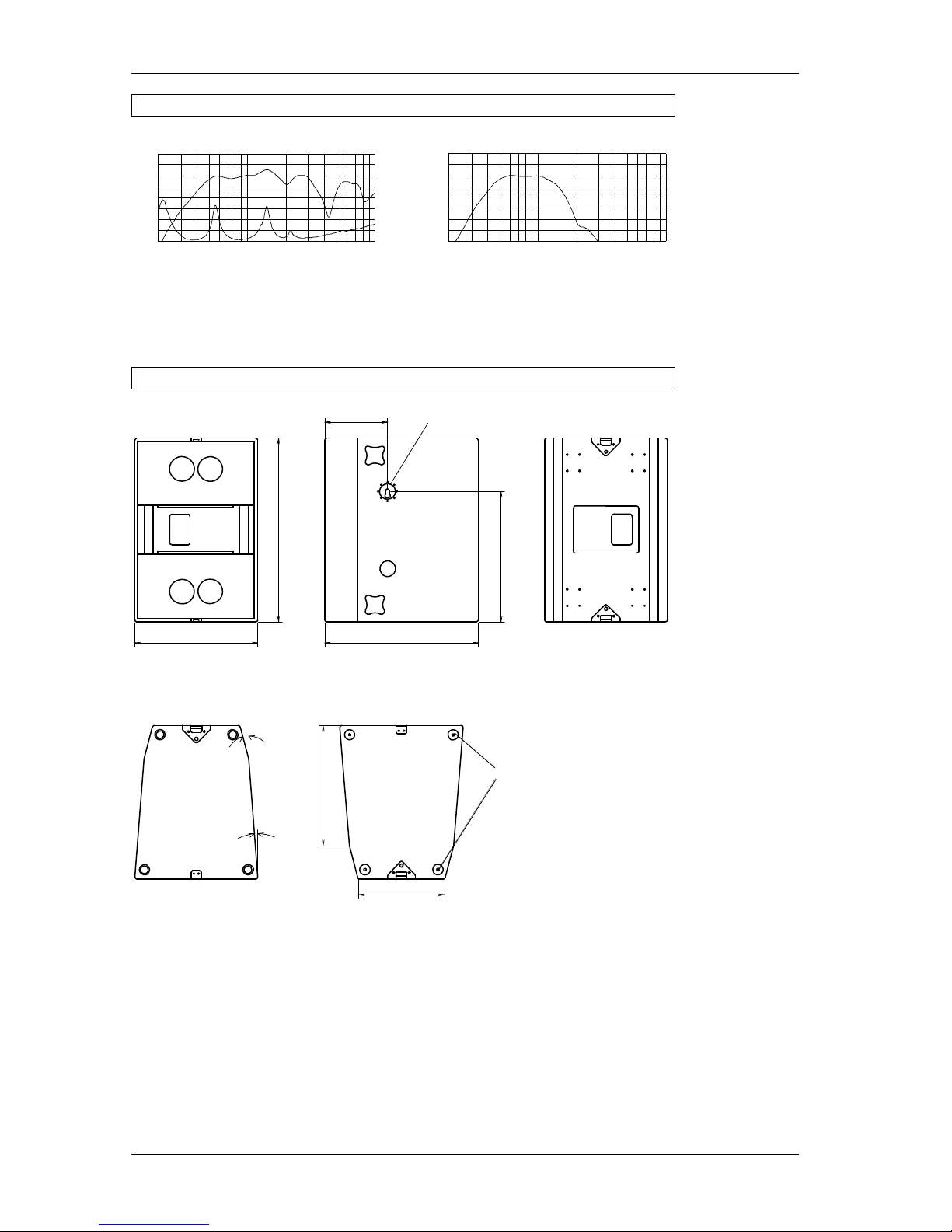
4.2.4 B5 Dimensions
Front View
Top View
15 °
4°
600 mm
Bottom View
Plastic Sliders
588 mm
MAN Rigging Point CF4T
307 mm
Side View
900 mm
421 mm
750 mm
639 mm
Rear View
Page 17

Operating Instructions ACCESS SYSTEM
KLING & FREITAG GMBH ©1995-2016 Version 6.2, 06.12.2016 Page 17 of 17
4.3 B10 Subwoofer System
4.3.1 B10 Applications
The B10 is a universally usable high-performance subwoofer system for the reproduction of low to very low frequencies. The B10 has been created to be used as the optimal
addition to the ACCESS Series. It is fully compatible with all existing Kling & Freitag
speaker products and shows off all its qualities here too. Because of its high efficiency
and technical perfection, the B10 is used in the high quality service segment, at discotheques and live sound coverage as well as venues with fixed installations such as theatres and multimedia facilities. The B10 allows for direct operation with ACCESS top
speakers T5 and T9 as well as a phase-correct parallel operation with the bass system
ACCESS B5. The B10 meets all demands at the highest level --- from techno to classic.
The B10 can be operated with the K&F controllers C5/9, C10 and C2.
4.3.2 B10 Technical Specifications
Design 3 chamber band-pass horn enclosure
Frequency response -10 dB 31 Hz - 320 Hz (without controller)
Frequency response ± 3 dB 38 Hz - 260 Hz (without controller)
Crossover frequencies max. 180 Hz, 130 Hz with controller C5/9
Nominal power handling 1) 1400 W
Programme power handling 2) 2800 W
Recommended amplification
2 - 3 kW @ 4 Ω
SPL 1 W/1 m 103 dB (40 Hz - 180 Hz)
Max. SPL 140 dB (SPL peak/1 m)
Components 18" long excursion transducers (2)
Impedance
2 x 8 Ω
With option 'EP-5 instead of Speakon': 1 x 4 Ω
Connectors EP-5 male / female, Sp.1: 2- / 3 +, Sp.2: 1- / 4 +
Enclosure 15 mm birch plywood with highly resistant
black structured paint
8 ergonomic butterfly handles
4 100 mm transport castors mounted on the rear,
ball proof front grille with exchangeable black
acoustic foam
Dimensions 600 x 1350 x 880 mm w/o castors (W x H x D)
Weight incl. castors 120 kg
Options Transport cover with butterfly catches,
special finish in RAL colours
1) Long term RMS power capability measured with pink noise signal, reduced bandwidth
40 Hz - 400 Hz, Testing period: 2 hours
2) Long term RMS power capability measured with 50% duty cycle,
reduced bandwidth 40 Hz - 400 Hz, Testing period: 2 hours
Page 18

Operating Instructions ACCESS SYSTEM
KLING & FREITAG GMBH ©1995-2016 Version 6.2, 06.12.2016 Page 18 of 18
4.3.3 B10 Measuring Charts
Fr
equenzgang
“
on axis
“
Alle Messungen unter Freifeldbedingungen. Frequenzgangdiagramme 1/6 Okt. geglättet.
Technische Änderungen, die der Verbesserung d er Produkte dienen, behalten wir uns
vor. Irrtümervorbehalten. Subject to change without notice.
20
Frequency(Hz)
SPL(dB)
3,16
31,6
316
Impedance (Ohm)
100
10
70
80
90
100
110
100 1000
4.3.4 B10 Dimensions
600mm
Draufsicht Unter
sicht
Plastic Sliders
Rear View
880mm
1350mm
600mm
Front View
Side View
Stacking
Moulds
Page 19

Operating Instructions ACCESS SYSTEM
KLING & FREITAG GMBH ©1995-2016 Version 6.2, 06.12.2016 Page 19 of 19
4.4 Using the ACCESS B5 / B10 with other K&F Systems
The bass systems B5 and B10 are also ideally suited as subwoofers for use with all models of the Kling & Freitag CA Series.
In order to guarantee an optimal tuning with the other K&F systems, it is necessary to
operate them via the K&F C2 System Controller. Additionally, the B10 can be operated
via the C10 Controller, although the K&F Full Range Systems are operated via the C2
Controller in full-range mode. Further information is available in the User’s Manual for
the K&F C2 Controller.
If the CA Series and an ACCESS Subwoofer System are to be operated by another universal controller, K&F will readily provide assistance upon request.
5. Pin Diagrams of Connectors and internal Wiring
5.1 ACCESS T5 Pin Diagrams of Connectors and Wiring
5.2 ACCESS T9 Pin Diagrams of Connectors and Wiring
ACCESS T9
K&F
HF
IN
HF
MF 1 / LOW MID
MF
IN
+1(+)2(-)
4(+)
3(-)
+
-
-
MF 2
COMPRESSION
UNIT
+
-
ACCESS T9
4
5
3
2
1
Input EP-5
(parallel to out)
HF
+
-
+
-
+
MF 1
MF 2
-
HF
-
MF
+ MF
+ HF
-
-
+
+
MF
HF
1-2
-
1+
2+
IN
4
5
3
2
1
Connector:
Ep-5
Parallel to out
Connector:
Speakon NL 4 MPR
Parallel to out
-
HF
-
MF
+ MF
+ HF
-
-
+
+
MF
HF
1-2
-
1+
2+
IN
4
5
3
2
1
Connector:
Ep-5
Parallel to out
Connector:
Speakon NL 4 MPR
Parallel to out
Page 20

Operating Instructions ACCESS SYSTEM
KLING & FREITAG GMBH ©1995-2016 Version 6.2, 06.12.2016 Page 20 of 20
5.3 ACCESS B5 Pin Diagrams of Connectors
Connector:
Speakon NL 4 MPR
1+ / 1
-
Speaker B
Speaker A
Speaker A
+
Speaker B
1-2
-
1+
2+
IN
With option 'EP-5 instead of Speakon':
Connector:
Ep-5
Parallel to out
-
Speaker B
-
Speaker A
+ Speaker A
+ Speaker B
4
5
3
2
1
5.4 ACCESS B10 Pin Diagrams of Connectors
Connector:
Speakon NL 4 MPR
1+ / 1
-
Speaker B
Speaker A
Speaker A
+
Speaker B
1-2
-
1+
2+
IN
With option 'EP-5 instead of Speakon':
Connector:
Ep-5
Parallel to out
-
Speaker B
-
Speaker A
+ Speaker A
+ Speaker B
4
5
3
2
1
Speaker B
Speaker A
Speaker B
Speaker A
Page 21

Operating Instructions ACCESS SYSTEM
KLING & FREITAG GMBH ©1995-2016 Version 6.2, 06.12.2016 Page 21 of 21
6. Safety Instructions for Controller and Connector Panel
Warning: To avoid electric shock hazard, do not expose this
appliance to rain or moisture. The enclosures may only be
opened by qualified personnel!
Do not install devices in any of the following place:
− where the units are permanently exposed to direct sunlight.
− near any heat sources and open fire. Do not put candles etc. on top of the unit.
− where the airflow for cooling is blocked.
− where it is exposed to high moisture.
− where it is exposed to strong vibrations and dust.
Power Supply
Before connecting the AC power cable of the unit, please check if the available voltage is compatible with the operating voltage as indicated on the unit. If this is not the
case, then the unit needs to be adapted by the manufacturer or an authorized service
centre. If the unit is not compatible with the available voltage, it should never be connected! This could irreparably ruin the unit.
Make sure that the power outlet supplies a ground connector, which must be connected to the unit via the PE conductor of the power cord!
Protection of electrical cables
Power cords should be laid in such a way that they are protected against footstep
damages, tensile strain and against being trapped.
Transportation
When transporting the equipment, make sure that it is protected from vibrations.
Cleaning
The equipment should only be cleaned with a damp cloth when it is not plugged in.
Pauses in use
The power cord should be disconnected from the power source during longer pauses
in use.
Intrusion of objects or liquids
No objects or liquids should intrude or leak into the equipment.
Maintenance and technical service
The user should not perform any maintenance work on the equipment other than
that which is described in this manual. Repairs may be executed by a qualified service
technician only.
In the following cases, the unit should be serviced by an authorized technician only if:
− the power cord or the mains connectors have been damaged.
− objects or liquids have gotten into it.
− it was exposed to rain.
− it doesn't appear to be functioning properly.
− it has fallen down or the enclosure is damaged.
Warning
Risk of electric shock!
Do not open the units!
AC
H
TUNG
Page 22

Operating Instructions ACCESS SYSTEM
KLING & FREITAG GMBH ©1995-2016 Version 6.2, 06.12.2016 Page 22 of 22
7. K&F CD 44 Digital System Controller
When using the Access System with CD 44, please refer the User's manual of the K&F
CD 44 Digital System Controller.
8. The ACCESS Controllers
If you have ACCESS subwoofers with Speakon connector where both drivers
are connected in parallel at pins 1+ / 1- (standard connection since april 2009),
they can not be used with the ACCESS controller without further ado.
For ACCESS subwoofers with this pin assignment we recommend operation with the
digital system controller K&F CD 44 and the K&F System Rack. Please refer to the CD 44
user's manual.
In order to operate current ACCESS subwoofers (standard since april 2009) with the
ACCESS controllers C5 / C9 / C10 and the Connector Panels CP1 / CP3 / CP1-B / CP3-B
we recommend ordering subwoofer with the option 'EP5 connector instead of
Speakon'. With this option you can operate ACCESS subwoofers with the ACCESS controllers and the Connector Panels according to this manual.
Operating safety and maximum performance of the ACCESS System can only be guaranteed when used with the C5/9 or C10 Controller. We cannot offer a warranty for
overload damage resulting from use with a controller aside from the ACCESS Controllers. If, despite this risk, the ACCESS System should be run with another controller,
please contact as for the corresponding information.
The ACCESS Controllers optimise the sound and operating safety of an ACCESS Sound
System. It assumes the role of a crossover and optimises the frequency-dependent
phase response and delay times. With the use of specially tuned filters (EQ), the ACCESS
Controllers optimise the ACCESS System’s frequency response.
A noteworthy function of the ACCESS Controller is its special limiter technology. With
other (universal) controllers, the gain of the selected power amplifiers must be known.
The limiter on the ACCESS Controller, on the other hand, uses a special control circuit
to determine the actual output voltage of the power amplifiers. The limiter then reduces
the input level only when the power amplifier actually provides more power than the
speakers can handle. The amplifier's gain and the position of the input level control for
the power amplifiers are insignificant for the limiter function of the ACCESS Controllers.
C5/9 Controller
The complete ACCESS System can be run with the C5/9 Controller. The C 5/9 is, thus,
capable of providing the signals for the top speakers T5/T9 as well as for the Bass Systems B5 or B10.
C10 Controller
The C10 Controller optimises the operations with the Bass System B10. Its possibilities
for operation include a configuration switch for various uses. It frees up the reserves
from the B10 for the sub-low range, thus providing a strong increase in bass performance.
Both ACCESS Controllers are compatible with the Kling & Freitag C2 Controller and
with most of the Kling & Freitag speaker systems. Because of this, the user has many
versatile possibilities to adjust the sound reinforcement to accommodate the needs and
requirements of a wide range of uses.
Important
Page 23

Operating Instructions ACCESS SYSTEM
KLING & FREITAG GMBH ©1995-2016 Version 6.2, 06.12.2016 Page 23 of 23
8.1 The ACCESS C5/9 Controller
8.1.1 Connectors, Controls and Displays and of the C5/9
1) CLUSTER / SINGLE
When using the ACCESS System in a cluster (several speakers beside one an-other), better
coverage results may be obtained if the CLUSTER/SINGLE switch is turned to the CLUSTER
position. In this operational mode the increase in sound pressure levels in the low/mid
range area resulting from cluster operation is compensated, and a largely linear frequency
response is achieved.
2) HIGHBOOST / NORMAL
The alignment of the ACCESS top speakers T5/T9 over long distances. High frequencies
are attenuated in the air over long distances. To compensate a decrease of high frequencies, the HIGHBOOST should be switched on. The position NORMAL produces a linear frequency response for short ranges.
3) LEVEL
With the LEVEL control, the input level of the ACCESS Controller can be adjusted.
Normally this control should be set to 0dB in order to avoid an overload of the input circuit
or the outputs of the mixing console.
4) CLIP
If this LED is lit up, the input of the C5/9 Controller is overloaded. Reduce the level on the
mixing console until the LED light remains off even at the highest volume.
5) INPUT SIGNAL
The three SIGNAL LEDs indicate the signal level. If the red LED (+10dB) lights up often or
continuously, turn down the LEVEL control on the ACCESS C5/9 Controller and turn up
the power amplifiers.
6) SENSE (GREEN) / LIMIT (RED)
The three SENSE/LIMIT-LEDs BASS, MID and HIGH have a double function.
a) The LEDs light up green when the sense cable is connected and the C5/9 Controller is
receiving an output signal from the power amplifiers.
b) When the relevant LED changes in colour from green to red, this indicates that the
C5/9 limiter is operating. A gradually setting-in RMS limiter and a fast peak limiter limit
the output power of the power amplifiers largely inaudibly down to the maximum
permissible value. If the red limiter LEDs light up frequently, then the level should be
slightly reduced. If necessary, the system should be supplemented with additional ACCESS speakers.
c) The EXCURSION LED indicates that the excursion limiter has been started.This circuit
analyses the output and frequency of the mid-range amplifier and calculates the signal
for the limiter. The amplifier's signal is sent to the SENSE connector on the back side of
the C5/9, which limits theoutput signal to the maximum permissible value.
In exceptional cases, the Sense LEDs may still light up even when the power amplifiers are turned off or disconnected. This situation is attributed to the ‘‘microphone effect’’ of the speakers. If the cones are moved (i.e. from air movement of
other sound sources), the speakers produce voltage which may cause the LEDs to
light up.
7) POWER ON
The POWER ON LED indicates that the system controller is on and operational. If the LED
does not light up after the equipment has been turned on, check the power supply or, if
necessary, replace the main fuse on the rear panel of the controller.
Front View
Important
1 2 3
4
765
CLUSTER
SINGLE
8
HIGH BOOST
NORMAL
A
C
C
E
S
S
C
5
/9
0
+6
LEVEL
CLIP
dB
SENSE (
GREEN
)/ LIMIT (
RED
)
H
IG
H
+
1
0
d
B
INPUT SIGNAL
-4
0
d
B
0
d
B
MIDE
X
C
U
R
S
I
O
N
B
A
S
S
O
N
POWER
ACCE S S
SYSTEM CONTROLLER
Page 24

Operating Instructions ACCESS SYSTEM
KLING & FREITAG GMBH ©1995-2016 Version 6.2, 06.12.2016 Page 24 of 24
8 9 10 11
12
13 1514
I
N
P
U
T
LINK
3
1
2
21
3
O
U
T
U
HIGH
T
P
L
I
T
F
3
1 2
MID
BASS
231 21
3
LINK
S
E
N
S
E
BASS HIGH + MID
Made in
READ MANUAL BEFORE USE
50-60Hz / 30VA
115 / 230VAC
T 500 / T 315mA
CONTROLLER K&F ACCESS C5/9
SEND (+15 V)
POWER SEQUENCE
Fuse 115 / 230V:
Power Requirements:
Serial Number:
Germany
KLING & FREITAG GmbH
2
3
0
115
SELECTOR
VOLTAGE
8) FUSE
Fuse holder which is fitted with a 315mA medium slow glass fuse for 230V operations. With 115V operations, a 500mA medium slow glass fuse must be used. Never
use a fuse with specificaations different than the aforementioned values. Never bypass the fuse holder. The system controller can be irreparably ruined and/or even
cause a fire.
9) VOLTAGE SELECTOR
This switch is used to adjust the equipment to the desired operational voltage level
of 115 or 230 VAC. CAUTION: the equipment can be destroyed if the wrong operating voltage level is selected!
10) SEQUENCE SEND
About 1 second after switching on the ACCESS Controller, a control voltage of
+15V is present at both connector pins. If, for example, you have fitted your amp
rack with power amplifiers that have a remote switching feature, then connect this
output with the SEQUENCE RCV input of the first amplifier, the SEQUENCE SND
output of the first amplifier with the SEQUENCE RCV input of the second amplifier,
etc. When turning on the ACCESS Controller, all amplifiers will then be turned on
time-delayed.
11) SENSE BASS
The amplified output signal of the bass amplifier is connected to the pins 1- and 1+
of this Speakon 4-pin connector. This signal provides the controller with information
for the bass-limiter. The ACCESS System also works without the connection from
the bass amplifier to the Sense Bass, but in this case, there is no guarantee for optimal operating safety. Make sure that the Speakon connector clicks into place
properly. All SENSE inputs are galvanically insulated from the amplifier with balanced transformers.
12) SENSE HIGH + MID und LINK
The amplified output signal of the mid-range and high amplifier is connected to
one of the two Speakon connectors. Here is where the ACCESS C5/9 Controller receives and evaluates the signals. It is extremely important to ensure that the polarity
is correct. The pin diagram for this is in the chapter for ‘‘Pin Diagrams of Connectors
and internal Wiring’’. The ACCESS System is connected to the respective Speakon
connector. The two connectors are connected in parallel.
13) OUTPUT - BASS, MID und HIGH
The electronically balanced BASS, MID and HIGH line level outputs are connected to
the inputs of the corresponding amplifier. We recommend using only high-quality
connecting cables from KLING & FREITAG. Bipolar shielded microphone cable with
high-quality connectors should be used to connect the power amplifiers. Connecting instructions are in the chapter for ‘‘Pin Diagrams of Connectors and internal
Wiring’’.
14) GROUND LIFT
If the Ground Lift switch is set on LIFT, then pin 1 of the INPUT connector is not
connected to the ACCESS C5/9 Controller. There is always a connection between
the INPUT (XLR male) and the LINK (XLR female) connector. If the C5/9 is operated
with a K&F Connector Panel, then this switch must be set to GROUND.
15) INPUT und INPUT-LINK
The C5/9 Controller is equipped with a transformer balanced input. Use the XLRfemale connectors (INPUT) as input. The parallel connected XLR-male connector is
used to link the signal to additional ACCESS controllers or amplifiers.
Rear View
Warning
Important
Important
Page 25

Operating Instructions ACCESS SYSTEM
KLING & FREITAG GMBH ©1995-2016 Version 6.2, 06.12.2016 Page 25 of 25
8.1.2 C5/9 Controller Technical Specifications
Input Nominal + 6 dB
+20 dB maximum level
20kΩ galvanically insulated
XLR connectors ( Pin 2 + )
Outputs Nominal +6 dB (+1.55 V) electronically balanced
XLR connectors ( Pin 2 + )
Control output + 15 Volt
Gain
Variable, - ∞ dB to +6 dB
Sense Galvanically insulated
Speakon 4-pin
Dynamic range >116 dB
THD ( THD+N ) < 0.02%
LED displays Clip
Signal -40 dB, 0 dB, +10 dB
Bass Sense (GREEN ) / Limit ( RED )
Mid Excursion Limit, Sense (GREEN), Limit (RED)
High Sense (GREEN) / Limit (RED)
Power
Switches
Front Single / Cluster
Normal / High Boost
Level
Rear Ground Lift
Voltage Selector
8.1.3 Pin Diagrams of the C5/9 Controller's In- and Outputs
I
N
P
U
T
LINK
3
1
2
21
3
O
U
T
U
HIGH
T
P
L
I
T
F
3
1 2
MIDBASS
231 21
3
LINK
S
E
N
S
E
BASS HIGH + MID
Made in
READ MANUAL BEFORE USE
50-60Hz / 30VA
115 / 230VAC
T 500 / T 315mA
CONTROLLER K&F ACCESS C5/9
SEND (+15 V)
POWER SEQUENCE
Fuse 115 / 230V:
Power Requirements:
Serial Number:
Germany
KLING & FREITAG GmbH
2
3
0
115
SELECTOR
VOLTAGE
SENSE BASS
SENSE / LINK
HIGH + MID
OUTPUT
BASS / MID / LOW
+
-
+ MT
+ HT
-
MT
-
HT
INPUT / LINK
parallel parallel
SEQUENCE (
+ 15V)
231
-
+
132
-
+
1-2
-
1+
2+
IN
1-2
-
1+
2+
IN
Page 26

Operating Instructions ACCESS SYSTEM
KLING & FREITAG GMBH ©1995-2016 Version 6.2, 06.12.2016 Page 26 of 26
8.2 The ACCESS C10 Controller
8.2.1 Connectors, Controls and Displays and of the C10
1) CONFIGURATION SWITCH
When operating the ACCESS B10, this switch can be used to select the appropriate filter presets. The following switch positions are available for the low-pass:
− 55 Hz: 12 dB / octave @ 47 Hz and 12 dB / octave @ 110 Hz
− 60 Hz: 12 dB / octave
− 120 Hz: 24 dB / octave
Stickers are included with the C10 Controller that document which preset is recommended for which application. The stickers can be put on where desired (i.e.
on the rack). It is important to recognize that the room and other factors can have
a crucial influence on the sound results. It is, therefore, possible that the configuration recommendations may, in some individual circumstances, vary from the optimal settings. The sound engineer’s ear must always make the final decision.
a) Operations with the C5/9 Controller:
I
0
II
T B5
B10
T
B10
T B5
B10
60Hz
55Hz
120Hz
C5/9-C10
If flown ACCESS Systems T5/T9 and B5 are
operated via the Controller C5/9 and the
B10 via the Controller
C10, the preset option
55 Hz is recommendable.
If standing ACCESS
Systems T5/T9 and B5
are operated via the
Controller C5/9 and
the B10 via the Controller C10, the preset
option 60 Hz is recommendable.
If the ACCESS Systems
T5/T9 without the
bass system B5 are
operated via the Controller C5/9 and the
B10 via the Controller
C10, the preset option
120 Hz is recommendable.
Front
1 2 3
4
765
SENSE (
GREEN
)/ LIMIT (
RED
)
120Hz
55Hz
60Hz
8
BASS BOOST
NORMAL
A
C
C
E
S
S
C
1
0
0
+6
LEVEL
CLIP
dB
+
1
0
d
B
-4
0
d
B
0
d
B
INPUT SIGNAL
B
A
S
S
B
S
Y
M
. E
R
R
O
R
B
A
S
S
A
O
N
POWER
A CCE S S
SYSTEM CONTROLLER
Page 27

Operating Instructions ACCESS SYSTEM
KLING & FREITAG GMBH ©1995-2016 Version 6.2, 06.12.2016 Page 27 of 27
b) Operations in combination with the K&F C2 Controller
TOP
L
TOP
R
B10
55Hz
-Flown tops via C2
-B10 via C10
C2 Settings:
FullrangeMode ON
C10 Low Pass Setting:
C2-C10
I
[
[
TOPLTOP
R
B10
60Hz
-Stackedtops via C2
-B10 via C10
C2 Settings:
Fullrange Mode OFF
C10 Low Pass Setting:
C2-C10
[
[
0
TOP
R
B10
sw
TOP
R
sw
- Tops with extra
Subwoofer via C2
C2 Settings:
Fullrange Mode OFF
C10 Low Pass Setting:
C2-C10
[
[
I
55Hz
If K&F full-range systems with K&F bass
systems are operated
via the C2 Controller,
and the B10 is operated via the C10 Controller as a supplementary bass system,
then the option fullrange mode ‘OFF‘
should be selected.
Generally, the configuration switch for
the C10 Controller
should be set at 55
Hz.
If flown K&F fullrange systems are to
be operated via the
C2 Controller and the
B10 as supplementary
bass system via the
C10 Controller, then
the option for the C2
Full Range Mode ‘ON‘
should be selected.
The configuration
switch on the C10
Controller should be
set at 55 Hz.
If top speakers which
are operated via the
C2 Controller are put
on top of the B10,
and the B10 is operated via the C10 Controller, then the option on the C2 Controller full-range mode
‘OFF‘ should be selected. The configuration switch on the
C10 Controller should
be set at 60 Hz.
2) BASSBOOST / NORMAL
If an increase of 40 Hz in the bass range is desired, then this range is increased by
approx. 3 dB when this switch is selected.
3) LEVEL
With the LEVEL control, the input level of the ACCESS Controller can be adjusted.
Normally this control should be set at 0dB in order to avoid an overload of the input
circuit or the outputs of the mixing console.
4) CLIP
If this LED is lit up, the input of the C10 Controller is overloaded. Reduce the level
on the mixing console until the LED light remains off even at the highest volume.
5) INPUT SIGNAL
The three SIGNAL-LEDs indicate the signal level in three steps. If the red LED (+10dB)
lights up often or continuously, turn down the LEVEL control on the ACCESS C10
Controller and turn up the power amplifiers.
6) SENSE (GRÜN) / LIMIT (ROT)
The two SENSE/LIMIT LEDs BASS A and BASS B have a double function.
a) The LEDs light up green when the sense cable is connected and the C10 Controller
is receiving an output signal from the power amplifiers.
b) When the relevant LED changes in colour from green to red, this indicates that the
C10 limiter has started. A soft starting RMS limiter and a fast Peak limiter regulate
the output of the amplifier inaudibly to the maximum admissible value. If the red
limiter LED lights up frequently, then the volume should be reduced slightly; if necessary, the system should be supplemented with additional ACCESS speakers.
In exceptional cases, the Sense LEDs may still light up even when the power
amplifiers are turned off or disconnected. This situation is attributed to the
‘‘microphone effect’’ of the speakers.
Important
Page 28

Operating Instructions ACCESS SYSTEM
KLING & FREITAG GMBH ©1995-2016 Version 6.2, 06.12.2016 Page 28 of 28
If the cones are moved (i.e. from air movement of other sound sources), the
speakers produce voltage which may cause the LEDs to light up.
c) The SYM: ERROR-LED indicates that there is a voltage difference of at least 5V be-
tween BASS A and BASS B. This LED also lights up if there is a phase error, in other
words, the phase between BASS A and BASS B is shifted by 180°. If this LED is lit
up, it is necessary to check the power amplifiers and the wiring.
7) POWER ON
The POWER ON LED indicates that the system controller is on and operational. If the LED
does not light up after the equipment has been turned on, check the power supply or, if
necessary, replace the main fuse on the rear panel of the controller.
8) FUSE
Fuse holder which is fitted with a 315 mA slow glass fuse in 230V mode. With 115V
operations, a 500mA slow glass fuse must be used. Never use a fuse with specifications
different than the aforementioned values. Never bypass the fuse holder. The system
controller can be irreparably ruined and/or even cause a fire.
9) VOLTAGE SELECTOR
This switch is used to adjust the equipment to the desired operational voltage level of
115 or 230 VAC. WARNING: the equipment can be destroyed if the wrong operating
voltage level is selected!
10)POWER SEQUENCE SEND
About 1 second after switching on the ACCESS Controller, a control voltage of +15V is
present at both connector pins. If, for example, you have fitted your amp rack with
power amplifiers that have a remote control feature, then connect this output with the
SEQUENCE RCV input of the first amplifier, the SEQUENCE SND output of the first amplifier with the SEQUENCE RCV input of the second amplifier, etc. When turning on the
ACCESS Controller, all amplifiers will then be turned on time-delayed.
11)SENSE INPUT BASS A / BASS B
Two independent sense inputs, which drive a common limiter circuit. The amplified
output signal of the bass amplifier is connected to the pins 1- and 1+ of this Speakon
4-pin connector. This signal provides the controller with information for the basslimiter. Make sure that the Speakon connector clicks into place properly. All SENSE
inputs are galvanically insulated from the amplifier with balanced transformers.
12)BASS OUT
The electronically balanced BASS line level outputs are connected to the inputs of the
corresponding amplifier. We recommend using only high-quality connecting cables from
KLING & FREITAG. Bipolar shielded connectors should be used to connect the power
amplifiers. Connecting instructions are in the chapter ‘‘Pin Diagrams of Connectors and
internal Wiring’’.
13)GROUND LIFT
If the Ground Lift switch is set on LIFT, then Pin 1 of the INPUT connector is not connected to the ACCESS C10 Controller. There is always a connection between the INPUT
(XLR male) and the LINK (XLR female) connector. If the C10 is operated with a K&F
Connector Panel, then this switch must be set on GROUND.
14)INPUT
The C10 Controller is equipped with a transformer balanced input. Use the XLR-female
connectors as input. The parallel connected XLR-male connector is used to link the signal to additional ACCESS controllers or amplifiers.
Rear
Warning
Important
Important
8 9
10
11
12
1413
SENSE BASS A
I
N
P
U
T
LINK
3
1
2
21
3
XLR
L
I
T
F
+
3
-
B
A
S
S
O
U
T
12
PARALLEL
231 21
3
-
SENSE BASS B
+1
+
-
2
IN
+-2
SPEAKON
1
50-60Hz / 30VA
115 / 230VAC
Made in
T 500 / T 315mA
CONTROLLER K&F ACCESS C10
READ MANUAL BEFORE USE
SEND (+15 V)
POWER SEQUENCE
Germany
Fuse 115 / 230V:
Power Requirements:
Serial Number:
KLING
2
3
0
115
SELECTOR
VOLTAGE
& FREITAG GmbH
Page 29

Operating Instructions ACCESS SYSTEM
KLING & FREITAG GMBH ©1995-2016 Version 6.2, 06.12.2016 Page 29 of 29
8.2.2 C10 Controller Technical Specifications
Input Nominal + 6 dB
+20 dB maximum Level
20kΩ galvanically insulated
XLR connectors ( Pin 2 + )
Outputs Nominal +6 dB ( +1.55 V ) electronically balanced
XLR connectors ( Pin 2 + )
Control output + 15 Volt
Gain
Variable, - ∞ dB to +6 dB
Sense Galvanically insulated
Speakon 4-pin
Dynamic range >116 dB
THD ( THD+N ) < 0.02%
LED Displays Clip
Signal -40 dB, 0 dB, +10 dB
Bass Sense (GREEN ) / Limit ( RED )
Sym.Error (RED)
Switches
Front Low pass filter 55 Hz / 60 Hz / 110 Hz
Normal / Bass Boost
Level
Rear Ground Lift
Voltage Selector
8.2.3 Pin Diagrams C10 Controller In- and Outputs
SENSE BASS A
I
N
P
U
T
LINK
3
1
2
21
3
XLR
L
I
T
F
+
3
-
B
A
S
S
O
U
T
12
PARALLEL
231 21
3
-
SENSE BASS B
+1
+
-
2 IN
+-2
SPEAKON
1
50-60Hz / 30VA
115 / 230VAC
Made in
T 500 / T 315mA
CONTROLLER K&F ACCESS C10
READ MANUAL BEFORE USE
SEND (+15 V)
POWER SEQUENCE
Germany
Fuse 115 / 230V:
Power Requirements:
Serial Number:
KLING
2
3
0
115
SELECTOR
VOLTAGE
& FREITAG GmbH
SENSE INPUT
BASS A / BASS B BASS OUT
+
-
INPUT / LINK
parallelparallel
SEQUENCE (
+ 15V)
231
-
+
132
-
+
1
-2-
1+
2+
IN
Page 30

Operating Instructions ACCESS SYSTEM
KLING & FREITAG GMBH ©1995-2016 Version 6.2, 06.12.2016 Page 30 of 30
9. The ACCESS Connector Panels
If you have ACCESS subwoofers with Speakon connector where both drivers
are connected in parallel at pins 1+ / 1- (standard connection since april 2009),
they can not be used with the ACCESS connector panel without further ado.
For ACCESS subwoofers with this pin assignment we recommend operation with the
digital system controller K&F CD 44 and the K&F System Rack. Please refer to the CD 44
user's manual.
In order to operate current ACCESS subwoofers (standard since april 2009) with the
ACCESS controllers C5 / C9 / C10 and the Connector Panels CP1 / CP3 / CP1-B / CP3-B
we recommend ordering subwoofer with the option 'EP5 connector instead of
Speakon'. With this option you can operate ACCESS subwoofers with the ACCESS controllers and the Connector Panels according to this manual.
9.1 Connectors of the Connector Panels CP1 and CP3
1) CP1 This model is designed to be connected to a 230 V mains supply.
The model with the code number ‘1‘ is recognizable by its power supply cable with
the blue plug on the front side of the equipment. (CEE 16 A, 3-pin, 230 V, 6 h)
2) CP3 This model is designed to be connected to a three-phase supply current
with 230 V per phase. The model with the code number ‘3‘ is recognizable by its
power supply cable with the red plug on the front side of the equipment. (CEE 16 A,
5-pin, 400 V, 6 h)
231
NEUTRIK
PUSH
132
NEUTRIK
132
NEUTRIK
1
2
3
4
5
1
2
3
4
5
1
2
3
4
5
1
2
3
4
5
BASS SPEAKER OUT
INPUT LINK BASS OUT
GROUND
ON OFF
TOP SPEAKER OUT MAINS
ACCESS
L / +
N
1 2 4 7
5 6
3
1) INPUT Balanced XLR input connector (female) for the input signal (e.g. the
signal from the mixing console)
2) INPUT --- LINK Balanced XLR output connector (male) to link the input signal
to other devices.
3) GROUND LIFT The Ground Lift switch serves to avoid ground loops. If the
Ground Lift switch is set on LIFT, then the Pin 1 (ground) of the input connector is
not connected to Pin 1 of the cable IN on the rear of the unit. There is always a connection between the INPUT connector (XLR-female) and the LINK connector (XLR-
male).
4) BASS OUT This output provides the optional transmission of the bass signal
supplied by the C5/9 Controller (LINE) to an additional power amplifier.
5) BASS SPEAKER OUT The bass speaker(s) are connected to these EP-5 connectors
(female). Both connectors are wired in parallel (no stereo signal!)
6) TOP SPEAKER OUT The mid-high speaker(s) are connected to the parallel EP-5
connectors (female) (no stereo signal).
7) Central Power Supply Cable
7a) The connector panel CP1 is equipped with a CEE connector 16A, 3-pin, 230V,
6h and serves as a connection to a 230V power supply. With this model, a total
of max. 16A can be connected to the 6 junction boxes.
7b) The connector panel CP3 is equipped with a red CEE connector 16A, 5-pin,
400V, 6h and serves as a connection to a three-phase current power supply with
230V per phase.
Front
Page 31

Operating Instructions ACCESS SYSTEM
KLING & FREITAG GMBH ©1995-2016 Version 6.2, 06.12.2016 Page 31 of 31
Power
Distribution
8 10 11 12
9
CP 3
CP 1
Phase 1 / L1
max. 16A
Phase 2 / L2
max. 16A
Phase 1 / L1
max. 16A
Phase 3 / L3
max. 16A
CONNE CTORPANEL CP3
Made in
Germany
Voltage:
Max. Total Output:
ProtectionLevel:
SerialNumber:
IP40
115/ 230VAC
3x 16A
8) JUNCTION BOXES
Grounding sockets to receive 230V.
8a) CP1: With this model, a total of max. 16A (not per socket!) can be received
from the 6 junction boxes.
8b) CP3: With this model, a total of max. 16A/phase (not per socket!) can be re-
ceived from the 6 junction boxes (2 sockets/phase), that means 3 x 16A!
9) MID-HIGH: Cable to the mid and high amplifier
This cable supplies the amplified output signal from the mid and high frequency power
amplifier. The signal is plugged into the „Sense Loop High + Mid/Low‘‘ connector of
the C5/9 System Controller and evaluated in the controller.
10) IN: Cable to the controller's ‘‘input‘‘
This cable supplies the input signal (from the front side of the connector panel) to
the input connector of the C5/9 Controller.
11) BASS A / BASS B: Cable to ‘‘bass amp out‘‘
This cable is connected to the respective speaker output of the bass power amplifier. The signal is transmitted to the BASS SPEAKER OUT connector (see item above)
on the front side of the device.
12) TO BASS OUT: Cable to ‘‘bass amp input link‘‘
This cable receives the line level signal which has not been amplified but has been
processed by the controller from the input connector of the bass amplifier. This signal is linked to the BASS OUT connector (see item 4 above) on the front side of the
device.
9.1.1 Connector Panel CP1 und CP3 Technical Specifications
Inputs Signal LINE: XLR
Speaker signal Low/Mid-High: 4-pin Speakon connector
Speaker signal bass: open wire
Bass LINE: open wire
CP 1 230 V CEE 3P 1 x 16 A
CP 3 400 V CEE 5P 3 x 16 A
Outputs Signal LINE Link: XLR
Bass LINE: XLR
Bass speaker: 2 X EP 5
Top speaker: 2 X EP 5
Max. current capability
CP 1 Total max. 16 A from 6 grounding outlets
CP 3 Total max 3 x 16 A from 3x2 grounding outlets (2 / phase)
Switches Ground Lift (front)
Dimensions 483 mm (19‘‘ ) x 88 mm (2U) x 325 mm ( W x H x D)
Weight
CP 1 6.95 Kg
CP 3 7.05 Kg
Rear View
Warning
Page 32

Operating Instructions ACCESS SYSTEM
KLING & FREITAG GMBH ©1995-2016 Version 6.2, 06.12.2016 Page 32 of 32
9.1.2 CP1 and CP3 Pin Diagrams of In- and Outputs
231
NEUTRIK
PUSH
132
NEUTRIK
132
NEUTRIK
1
2
3
4
5
1
2
3
4
5
1
2
3
4
5
1
2
3
4
5
BASS SPEAKER OUT
INPUT LINK BASS OUT
GROUND
ON OFF
TOP SPEAKER OUT MAINS
ACCESS
L / +
N
-
Speaker B
L / +
L 1
N
L 2
L3
N
-
Speaker A
+ Speaker A
+ Speaker B
+
-
-
+
CP 1
CP 3
MF
HF
132
-
+
4
5
3
2
1
4
5
3
2
1
231
-
+
+ MT
+ HT
-
MT
-
HT
1
-
2
-
1+
2+
IN
CONN ECTORPAN EL CP3
Made in
Germany
Voltage:
Max. Total Output:
Protection Level:
SerialNumber:
IP40
115/ 230VAC
3x 16A
redblack blue white
redblack
blue
-
+
231
-
+
Front
Rear
Outputs to
bass speaker
B5 / B10
Output to
high/mid
speaker
T5 / T9
Line level
input, e.g.
from mixing
console and
link connector
for linking the
LINE input
signal e.g. to
additional
amplifier racks
Power supply
Line level
output for
optional
linking of
signals processed by C5/9
Controller,
e.g. to additional amplifiers
BASS A
To speaker
output of bass
amplifier / signal
for speaker A
BASS B
To speaker
output of bass
amplifier /
signal
for speaker B
IN
To input
of C5 Controller
MID-HIGH
To ‘‘SENSE-LOOP
HIGH + MID/LOW‘‘ --input connector of
C5 - Controller
TO BASS OUT
Controller signal
pick-off from the
input of the bass
amplifier (line level)
Page 33

Operating Instructions ACCESS SYSTEM
KLING & FREITAG GMBH ©1995-2016 Version 6.2, 06.12.2016 Page 33 of 33
9.2 Connectors of the Bass Connector Panels CP1-B und CP3-B
3) CP1-B
This model is designed to be connected to a 230 V mains supply.
The model with the code number ‘1‘ is recognizable by its power supply cable with
the blue plug on the front side of the equipment.
(CEE 16 A, 3-pin, 230 V, 6 h)
4) CP3-B
This model is designed to be connected to a three-phase supply current with 230 V
per phase. The model with the code number ‘3‘ is recognizable by its power supply
cable with the red plug on the front side of the equipment.
(CEE 16 A, 5- pin, 400 V, 6 h)
Front
1 2 4
5
6
3
BASS SPEAKER OUT
231
NEUTRIK
PUSH
132
NEUTRIK
INPUT LINK BASS OUT
GROUND
ON OFF
MAINS
ACCESS
1
234
5
231
NEUTRIK
PUSH
132
NEUTRIK
132
NEUTRIK
1
234
5
L / +
N
1) INPUT
Balanced XLR input connector (female) for the input signal (e.g. the signal from the
mixing console)
2) INPUT --- LINK
Balanced XLR output connector (male) to link the input signal to other devices
3) GROUND LIFT
The Ground Lift switch serves to avoid ground loops. If the Ground Lift switch is set
on LIFT, then the Pin 1 (ground) of the input connector is not connected to Pin 1 of
the cable IN on the rear of the unit. There is always a connection between the input
connector (XLR-female) and the link connector (XLR-male).
4) BASS OUT
This output provides the optional transmission of the bass signal supplied by the
C5/9 Controller (LINE) to an additional power amplifier.
5) BASS SPEAKER OUT
The bass speaker(s) are connected to these EP-5 connectors (female). Both connectors are wired in parallel (no stereo signal!)
6) Central Power Supply Cable
6a) The connector panel CP1-B is equipped with a CEE connector 16A, 3-pin,
230V, 6h and serves as a connection to a 230V mains supply. With this model, a total of max. 16A can be connected to the 6 junction boxes.
6b) The connector panel CP3-B is equipped with a red CEE connector 16A, 5-pin,
400V, 6h and serves as a connection to a three-phase current supply with 230V
per phase. Please see also topic 7 on the next page.
Page 34

Operating Instructions ACCESS SYSTEM
KLING & FREITAG GMBH ©1995-2016 Version 6.2, 06.12.2016 Page 34 of 34
REAR VIEW
Power
Distribution
7 10 11
8 9
CP3-B
CP1-B
Phase 1 / L1
max. 16A
Phase 2 / L2
max. 16A
Phase 1 / L1
max. 16A
Phase 3 / L3
max. 16A
CONNEC TORPANEL CP1- B
Made in
Germany
Voltage:
Max. Total Output:
ProtectionLevel:
SerialNumber:
IP40
115/230 VAC
3x 16A
7) JUNCTION BOXES
Grounding sockets to receive 230V.
7a) CP 1: With this model, a total of max. 16A (not per socket!) can be received
from the 6 junction boxes.
7b) CP 3: With this model, a total of max. 16A/phase (not per socket!) can be re-
ceived from the 6 junction boxes (2 sockets/phase), that means 3 x 16A!
8) TO INPUT: Cable with XLR-male connector to the controller's "input"
This cable supplies the input signal from the front side of the connector panel to
the input connector of the C10 Controller.
9) BASS OUT: Cable with XLR-female connector from the „BASS OUT‘‘ connector of
the C10 Controller. The signal can then be received from the BASS OUT connector
at the front of the panel (4).
10) OUTPUT BASS A / OUTPUT BASS B: This cable is connected to the respective
speaker output of the bass power amplifier. The signal is transmitted to the BASS
SPEAKER OUT connector (5) on the front side of the device
11) SENSE BASS A / SENSE BASS B: These cables provide the signal of the power
amplifier for the corresponding SENSE INPUT connectors of the C10 Controller
where the signal is evaluated.
9.2.1 Connector Panel CP1-B und CP3-B Technical Specifications
Inputs Signal LINE: XLR
Speaker signal Low/Mid-High: 4-pin Speakon connector
Speaker signal Bass: open wire
Bass LINE: open wire
CP 1 230 V CEE 3P 1 x 16 A
CP 3 400 V CEE 5P 3 x 16 A
Outputs Signal LINE Link: XLR
Bass LINE: XLR
Bass speaker: 2 X EP 5
Top speaker: 2 X EP 5
Max. current capability
CP 1 Total max. 16 A from 6 grounding outlets
CP 3 Total max 3 x 16 A from 3x2 grounding outlets (2 / phase)
Switches Ground Lift (front)
Dimensions 483 mm (19‘‘ ) x 88 mm (2U) x 325 mm (W x H x D)
Weight
CP 1 6.95 kg
CP 3 7.05 kg
Warning
Page 35

Operating Instructions ACCESS SYSTEM
KLING & FREITAG GMBH ©1995-2016 Version 6.2, 06.12.2016 Page 35 of 35
9.2.2 CP1-B and CP3-B Pin Diagrams of In- and Outputs
Front
BASS SPEAKER OUT
231
NEUTRIK
PUSH
132
NEUTRIK
INPUT LINK BASS OUT
GROUND
ON OFF
MAINS
ACCESS
1
2
3
4
5
231
NEUTRIK
PUSH
132
NEUTRIK
132
NEUTRIK
1
2
3
4
5
L / +
N
-
Speaker B
L / +
L 1
N
L 2
L3
N
-
Speaker A
+ Speaker A
+ Speaker B
CP1-B
CP3-B
132
-
+
4
5
3
2
1
231
-
+
CONN ECTORPAN EL C P1-B
Made in
Germany
Voltage:
Max. Total Output:
Protection Level:
SerialNumber:
IP40
115/ 230VAC
3x 16A
-
-
+
231
1
2
3
-
+
1 2
1+ 2
-
3+
1+
1
-
Outputs to speakers
Input, e.g. from
mixing console and
link connector for
linking the input
signal to e.g. other
amplifier racks
Power supply
Output for optional
linking of the signal
processed by the C10
Controller, e.g. to
additional amplifiers
Output Bass A
To speaker
output of power
amplifier for
speaker A
Output Bass B
To speaker
output of power
amplifier for
speaker B
Sense Bass B
To SENSE INPUT
‚Speaker B‘ of the
C10 Controller
To Input
To Input of C10
Controller
Sense Bass A
To SENSE INPUT
‚Speaker A‘ of the
C10 Controller
Bass Out
To Bass Out of C10
Controller
Page 36

Operating Instructions ACCESS SYSTEM
KLING & FREITAG GMBH ©1995-2016 Version 6.2, 06.12.2016 Page 36 of 36
10. Connecting Instructions for the ACCESS System
10.1 Wiring
The speaker is equipped with two parallel EP-5 or with Speakon NL4 connectors.
Make sure that all units are switched off and all controls are turned down be-fore con-
necting your ACCESS system.
− We recommend the use of high-quality speaker cables provided by Kling & Freitag.
− For connections to the power amplifier inputs, please use 2-pin shielded micro-
phone cable with high-quality connectors.
− Avoid ground loops (see next chapter)
− Please pay attention to the respective pin diagrams in this manual!
− To ensure an in-phase operation and, consequently, a homogeneous sound, make
sure that the +/- polarity of the speakers at the amplifier is correct.
− When simultaneously using power amplifiers from different manufacturers, be sure
to use the correct specific pin configuration. It may be necessary to modify the pin
configuration on the power amplifiers or on the connectors leading to them.
− -To avoid loss of power, the cables should have a minimum wire gauge of 2.5 mm²
- more for longer cabled distances. A minimum wire gauge can be easily calculated
with the following formula:
Make sure that the EP-5-‘Male’ socket with the exposed contacts (male) is used
as input to avoid physical contact with dangerous currents!
If several loudspeakers are connected, the signal can be linked through from one loudspeaker to the next. Please make sure that the total impedance of the loudspeakers R(Ω) is
not lower than the minimal impedance indicated on the power amplifier.
1/R
1
+ 1/R2 + 1/R3 + ... = 1/R
total
Important
Warning
Minimum Wire Gauge (mm²) =
Required Cable Length (m)
2 x Speaker Impedance (Ω)
Page 37

Operating Instructions ACCESS SYSTEM
KLING & FREITAG GMBH ©1995-2016 Version 6.2, 06.12.2016 Page 37 of 37
10.2 Avoiding Ground Loops
10.2.1 What is a Ground Loop?
Every component of a P.A. or Hi-Fi system has its own internal 0 V reference (ground). This
point is often connected to the protective earth connector (PE / Ground). If two or more
units are connected to one another with a line level audio cable, there may be a ground
connection through the ground of the power supply cable (yellow-green) as well as
through the shielding of the audio cable. The voltage difference between these two
ground points causes audible interference to come from the speaker.
10.2.2 Avoiding Ground Loops
If there is a loud humming or buzzing after the ACCESS system has been connected,
then check that a "ground loop" has not been built into the system. Some power amplifiers and system controllers are equipped with a "Ground Lift" switch. Set these
switches to the "Lift" position one after the other. If the noise is still audible, check if,
1. the noise is caused by a ground loop before the power amplifiers / controllers
(e.g. mixing console, effects or equalizers).
2. the system or parts of the system are connected to an "unclean" power sup-ply
- meaning one, which is also running large motors, or lighting systems. An
"unclean" supply voltage, electrostatic and electromagnetic fields can cause a
malfunction.
Please observe the following basic rules:
− Never!!! try to avoid a ground loop by disconnecting or taping the ground
contact at the power connector! Extremely dangerous!
− If possible, only use high-quality audio appliances with balanced signal outputs and
with power cables with PE connectors.
− Use high-quality cables with good shielding
− The point of ground for all connected components should merge at one central
point. The power connections should lead out in a radial manner from one point
and not be linked from one unit to the next.
− When installing appliances that create strong electrostatic or electromagnetic fields
(large transformers, switch-mode power supplies), maintain some distance from
other audio appliances. In extreme cases, the only solution is to create a completely
independent ‘audio ground’; in other cases, it is sufficient to connect a filter in front
of the audio equipment.
Important
Warning
Important
Page 38

Operating Instructions ACCESS SYSTEM
KLING & FREITAG GMBH ©1995-2016 Version 6.2, 06.12.2016 Page 38 of 38
11. Recommended Amplifier Performance for the ACCESS System
An audio system is expected to transmit dynamic signals and peaks without distortion.
This needs to be considered when determining if a power amplifier is adequate for a
speaker system. Possible peak power levels of an amplifier are more relevant in this
consideration than the RMS power (continuous power output, root mean square value)
generally provided by the manufacture.
Unfortunately, an amplifier’s RMS power is no indication for its specific peak power. The
difference between peak and RMS power is, however, generally lower with operations
with high impedance load than with low impedance operations.
Because of this, we also specify a recommended peak power (10ms/1kHz) in addition to
the usual RMS power recommendation. This peak power can be calculated or provided
by the manufacturer of the respective equipment.
1. 1 Power Amplifier for 1 x T5 / T9:
2 x 700-900 W RMS (1000 W peak )/ 4Ω
1 x Controller K&F C5/9
2. 1 Power Amplifier for 2 x T5 / T9:
2 x 1100-1500 W RMS (2000 W peak) / 2Ω
1 x Controller K&F C5/9
3. 1 Power Amplifier for 2 x mid channel:
2 x 700-900 W RMS (1000 W peak) / 4Ω
1 Power Amplifier for 2 x high channel:
2 x 200-250 W RMS (250 W peak) / 8Ω
2 x Controller K&F C5/9
4. 1 Power Amplifier for 1 x B5:
2 x 700-800 W RMS (850 W peak) / 8Ω
1 x Controller K&F C5/9
Page 39

Operating Instructions ACCESS SYSTEM
KLING & FREITAG GMBH ©1995-2016 Version 6.2, 06.12.2016 Page 39 of 39
5. 1 Power Amplifier for 2 x B5:
2 x 1200-1400 W RMS (1700 W peak) / 4Ω
1 x Controller K&F C5/9
6. 1 Power Amplifier for 1 x B10:
2 x 700-1000 W RMS (1000 W peak) / 8Ω
1 x Controller K&F C5/9
7. 1 Power Amplifier for 2 x B10:
2 x 1200-1600 W RMS (2000 W peak) / 4Ω
1 x Controller K&F C5/9
11.1 Correct Bass and Top Speaker Ratio
When making adjustments on the power amplifier, it is extremely important that the
volume levels for the top speakers T5/T9 and the amplifiers for the bass systems are
correct.
The C5/9 Controller is designed so that when a top speaker T5/T9 and two ass speakers
B5 are combined, the power amplifier’s gain for the tops should be approx. 3dB lower
than the gain of a bass power amplifier in stereo- and dual-mono operations (with level
controls at maximum).
This ratio can change with other configurations. One reason for this is the different
dispersion coverage of bass and mid/high speakers. When the number of basses is doubled, the volume of basses set up next to each other can increase by max. +6dB (+3dB
efficiency and +3dB from doubling the amplifier’s power). The level of the tops does not
increase in this manner because of the directivity.
The position of a bass speaker has a large influence on the actual volume. A bass speaker on the floor can be a few decibels louder than a flown bass system because of floor
reflections. Because of this, the sound engineer must always do some fine-tuning on the
amplifier controls (not on the mixing console!) when tuning the system.
The gain of the power amplifier is generally found in the user’s manual.
Customized adjustment of the C5/9 Controller to individual power amplifiers
If the C5/9 Controller should be customized to the particular amplifiers with which it will
be used, please contact KLING & FREITAG GmbH. We would be happy to adjust the
C5/9 Controller to meet your individual needs. In doing so, it would generally no longer
be necessary for the owner to make further adjustments on the power amplifiers when
using the standard configuration 1 x T5 or T9 and 2 x B5.
Page 40

Operating Instructions ACCESS SYSTEM
KLING & FREITAG GMBH ©1995-2016 Version 6.2, 06.12.2016 Page 40 of 40
12. Mounting Instructions for Loudspeakers
Mount the speakers securely. To avoid injury or damage, always be sure to mount the
speakers securely so that they do not fall. Speakers, which are stacked, must be secured with securing straps. When laying the connecting cables, make sure that no-body
can trip.
The stability of stacked systems (also valid for the use of stands and distance rods!) is
contingent upon the following stability requirement. These conditions must, therefore,
be guaranteed by the user:
Stacked systems may not fall over even if they are incline
Stacked systems may not fall over even if they are inclineStacked systems may not fall over even if they are incline
Stacked systems may not fall over even if they are inclined by 10° in each dire
d by 10° in each dired by 10° in each dire
d by 10° in each direcccction.
tion. tion.
tion.
If this requirement is not fulfilled, then it is necessary to take steps to achieve
If this requirement is not fulfilled, then it is necessary to take steps to achieve If this requirement is not fulfilled, then it is necessary to take steps to achieve
If this requirement is not fulfilled, then it is necessary to take steps to achieve
compliance. Possible measures include strapping it to an appropriate
compliance. Possible measures include strapping it to an appropriatecompliance. Possible measures include strapping it to an appropriate
compliance. Possible measures include strapping it to an appropriate----ate base
ate base ate base
ate base
structure or fastening it using safety straps.
structure or fastening it using safety straps.structure or fastening it using safety straps.
structure or fastening it using safety straps.
Warning
Page 41

Operating Instructions ACCESS SYSTEM
KLING & FREITAG GMBH ©1995-2016 Version 6.2, 06.12.2016 Page 41 of 41
12.1 Mounting and Stacking the ACCESS Systems
1.)
2.)
Reach into the speaker’s butterfly
handles...
...and turn the speaker onto its
lower edge.
3.)
4.)
Lean the speaker farther forward
and press your body weight against
it so that the speaker does not suddenly fall forward.
Lift up the next speaker with a second person, as illustrated. Make
sure to lift from your knees and not
your back.
5.)
6.)
Set the bottom side of the speaker
on the back edge of the bottom
speaker. Put the speaker up on top
with a sweeping movement of the
arm.
Shove the speaker into the correct
position so that the stacking feet fit
on top of the grooves of the lower
speaker. Secure the speaker add
Secure the speaker addSecure the speaker add
Secure the speaker addi-
i-i-
i-
tionally with a securing strap.
tionally with a securing strap.tionally with a securing strap.
tionally with a securing strap.
Warning
Page 42

Operating Instructions ACCESS SYSTEM
KLING & FREITAG GMBH ©1995-2016 Version 6.2, 06.12.2016 Page 42 of 42
12.2 Using the MAN Rigging Points
Eyebolt MAN installation stud.
To be used with fixed installations.
No
No No
No
additional speakers may by suspen
additional speakers may by suspenadditional speakers may by suspen
additional speakers may by suspend-
d-d-
d-
ed from the eyebolt MAN install
ed from the eyebolt MAN installed from the eyebolt MAN install
ed from the eyebolt MAN installa-
a-a-
a-
tion stud.
tion stud.tion stud.
tion stud.
Eye bolt MAN stud plate (HWSP)
To be used with mobile installations.
1.)
1.)
Loosen all but the last two threads of
the stud’s nut. Put the eyebolt in the
speaker’s receptacle so that the tip of
the nut points down.
Pull up the eyebolt’s locking device
with the thumb and index finger
and put the eyebolt into the speaker’s receptacle.
2.)
2.)
Pull up the eyebolt and screw it in
tightly. Then loosen the eyebolt by
maximal ½ turn so that it cannot be
tightened all the way when the speaker is tilted.
Pull up the eyebolt while pulling on
the locking device. Then let go of
the locking device.
3.)
3.)
Make sure that the eyebolt is stable
and that it cannot be pulled down.
Make sure that the eyebolt is stable
and that it cannot be pulled down.
4.)
When using chains, make sure that the
openings of the hooks are always
turned toward the front side of the
speaker.
Warning
Page 43

Operating Instructions ACCESS SYSTEM
KLING & FREITAG GMBH ©1995-2016 Version 6.2, 06.12.2016 Page 43 of 43
13. Operating the ACCESS SYSTEM
− Make sure to observe the instruction in the loudspeaker’s manual as well as in the
included safety and mounting Instructions for loudspeakers and accessories.
− Switch off all equipment and turn off all controls.
− Wire the ACCESS System according to the pin diagrams as shown before.
− Now switch on the peripheral equipment first (mixing console, effects etc.), fol-
lowed by the ACCESS Controller and the power amplifiers. Always use the before
mentioned switching order. Otherwise switching noises may damage the system.
− If there is interference, turn off all appliances in the reverse order and check all
cable connections.
− Turn up the input controls of the amplifiers. If there is interference, turn off all
appliances in the reverse order and check all cable connections.
− Next, turn on the ACCESS Controller and the other peripheral equipment and
make sure there is no interference.
− Now put a low level signal into the system and check for the correct function of
the ACCESS System. In doing so, all amplifier input controls need to be turned off
again. Turn on the control for the left high channel and check that the correct
high signal is coming out of the high chassis in the left speaker. The Sense LED for
the high channel of the respective ACCESS C5 Controller will light up green at a
level of at least ---40dB. If the wrong LED lights up or a wrong (i.e. high signal from
a bass speaker) or distorted signal occurs, then there is a mistake in the wiring.
− The system is now ready to operate. The power amplifiers can now be turned on
all the way (see also LEVEL). Use the LEVEL control on the ACCESS Controller to
set the level of the ACCESS System to the desired setting.
− The levels on the mixing console can now be turned up. When turning off the sys-
tem, the input controls for the power amplifiers should be switched off first followed
by the amplifiers. After that, the other appliances can be turned off.
Important
Important
Page 44

Operating Instructions ACCESS SYSTEM
KLING & FREITAG GMBH ©1995-2016 Version 6.2, 06.12.2016 Page 44 of 44
14. Connection Diagrams
14.1 ACCESS System with Controller C5/9 and CP1/3
INPUT e.g. from mixer, AUX or Connector Panel LINK e.g. to next Connector Panel or Controller
To bass out
Bass A / Bass B
Mid-High
In
BASS OUT for extra Bass Amp
MAIN SUPPLY
CP1: 230V / CP3 400V
B10 or B5 T5 or T9
MAX.16A
CONNECTOR PANEL CP3
Made in
Germany
Voltage:
Max. Total Output:
Protection Level:
Serial Number:
IP 40
115 / 230 VAC
3 x 16A
SEQUENCE
RCV
INPUT CH 2 INPUT CH 1
OUTPUTS
SND
CH 2 CH 1
CH 2 CH 1 (Mono)
Inputs
CH2
CH 1
Sequence
Ch 2
Ground
Lift
Ch 1
snd rcv snd rcv
If available use
Dual Mono Mode
Connect to amplifier input link
If Mono Mode is
not available,
link CH 1
to CH 2
and turn
both
chanels
to the
same
level
+
-
-
+
-
+
-
+
red label
In combination with
Connector Panel:
Set Ground Lift
always on "Ground"
yellow label
green label
Dual Mono
3
BASS SPEAKER OUT
INPUT LINK BASS OUT
GROUND
ON OFF
TOP SPEAKER OUT MAINS
ACCESS
L 1
N
L 2
L 3
red
black
blue
-
+
HIGH MID
MID 1+ / 1-HIGH 2+ / 2-
+15V e.g. for optional
power sequencing
Bass B
Bass A
3
1 2132 21
3
POWER SEQUENCE
VOLTAGE
SELECTOR
Germany
CONTROLLER K&F ACCESS C5/9
T 500 / T 315mA
115 / 230VAC
50-60Hz / 30VA
READ MANUAL BEFORE USE
SEND (+15 V)
Made in
Serial Number:
Power Requirements:
Fuse 115 / 230V:
115
2
3
0
FREITAG GmbH&KLING
I
N
P
U
T
3
1 2
2
1
3
LINK
F
T
I
L
BASS MID
P
T
HIGH
U
T
U
O
Page 45

Operating Instructions ACCESS SYSTEM
KLING & FREITAG GMBH ©1995-2016 Version 6.2, 06.12.2016 Page 45 of 45
14.2 ACCESS System with Controller C5/9, no Connector Panel
MID OUT (1+ / 1-) / HIGH OUT (2+ / 2-)
MID
HIGH
SEQUENCE
RCV
INPUT CH 2 INPUT CH 1
SND
Sequence
Ch 2
Ground
Lift
Ch 1
snd rcv snd rcv
T5 or T9
B10 or B5
Dual Mono
HIGH MID
BASS
SPEAKER A
BASS
SPEAKER B
OUTPUTS
CH 2 CH 1
-
+
-
+
CH2
CH 1
+
-
-
+
Bass B
Bass A
CH 2 CH 1 (Mono)
Inputs
If available use
Dual Mono Mode
If Mono Mode is
not available,
link CH 1
to CH 2
and turn
both
chanels
to the
same
level
+15V e.g. for optional
power sequencing
MID/LOW 1+ / 1-HIGH 2+ / 2-
3
1 2132 21
3
POWER SEQUENCE
VOLTAGE
SELECTOR
Germany
CONTROLLER K&F ACCESS C5/9
T 500 / T 315mA
115 / 230VAC
50-60Hz / 30VA
READ MANUAL BEFORE USE
SEND (+15 V)
Made in
Serial Number:
Power Requirements:
Fuse 115 / 230V:
115
2
3
0
FREITAG GmbH&KLING
I
N
P
U
T
3
1 2
2
1
3
LINK
F
T
I
L
BASS MID
P
T
HIGH
U
T
U
O
Page 46

Operating Instructions ACCESS SYSTEM
KLING & FREITAG GMBH ©1995-2016 Version 6.2, 06.12.2016 Page 46 of 46
14.3 Optimised Operations with B10, C10 and CP1/3-B
INPUT e.g. from
mixer, AUX or
Connector Panel
LINK e.g. to next Connector Panel or Controller
BASS OUT for extra Bass Amp
MAIN SUPPLY
CP1-B: 230V / CP3-B 400V
BASS A BASS B
MAX.16A
CONNECTORPANE L CP3-B
Made in
Germany
Voltage:
Max. Total Output:
ProtectionLevel:
SerialNumber:
IP40
115/230 VAC
3x 16A
CH 2 CH 1 (Mono)
Inputs
CH2
CH 1
Sequence
Ch 2
Ground
Lift
Ch 1
snd rcv snd rcv
If available use
Dual Mono Mode
If Mono Mode is
not •available,
link CH 1
to CH 2
and turn
both
chanels
to the
same
level
+
- -
+
In combination with
Connector Panel:
Set Ground Lift
always on "Ground"
green label
Dual Mono
BASS SPEAKER OUT
231
NEUTRIK
PUSH
132
NEUTRIK
INPUT LINK BASS OUT
GROUND
ON OFF
MAINS
ACCESS
L 1
N
L 2
L 3
1
2
3
4
5
231
NEUTRIK
PUSH
132
NEUTRIK
132
NEUTRIK
1
2
3
4
5
+15V e.g. for optional
power sequencing
SENSE BASS A
I
N
P
U
T
LINK
3
1
2
21
3
XLR
L
I
T
F
+
3
-
B
A
S
S
O
U
T
12
PARALLEL
231 21
3
-
SENSE BASS B
+1
+
-
2 IN
+-2
SPEAKON
1
50-60Hz / 30VA
115 / 230VAC
Made in
T 500 / T 315mA
CONTROLLER K&F ACCESS C10
READ MANUAL BEFORE USE
SEND (+15 V)
POWER SEQUENCE
Germany
Fuse 115 / 230V:
Power Requirements:
Serial Number:
KLING
2
3
0
115
SELECTOR
VOLTAGE
& FREITAG GmbH
Bass B Bass A
2
Sense A
OUT
IN
Sense B
1
Page 47

Operating Instructions ACCESS SYSTEM
KLING & FREITAG GMBH ©1995-2016 Version 6.2, 06.12.2016 Page 47 of 47
14.4 Optimised Operations with B10, C10 without CP1/3-B
Sequence
Ch 2
Ground
Lift
Ch 1
snd rcv snd rcv
Dual Mono
BASS
SPEAKER A
BASS
SPEAKER B
CH2 CH 1
+
- -
+
Bass B
Bass A
INPUT e.g. from mixer
INPUT LINK e.g. to next C5/9 or C10 etc.
PARALLEL BASS OUT e.g. to next amp
CH 2 CH 1 (Mono)
Inputs
If available use
Dual Mono Mode
If Mono Mode is
not available,
link CH 1
to CH 2
and turn
both
chanels
to the
same
level
+15V e.g. for optional
power sequencing
SENSE BASS A
I
N
P
U
T
LINK
3
1
2
21
3
XLR
L
I
T
F
+
3
-
B
A
S
S
O
U
T
12
PARALLEL
231 21
3
-
SENSE BASS B
+1
+
-
2 IN
+-2
SPEAKON
1
50-60Hz / 30VA
115 / 230VAC
Made in
T 500 / T 315mA
CONTROLLER K&F ACCESS C10
READ MANUAL BEFORE USE
SEND (+15 V)
POWER SEQUENCE
Germany
Fuse 115 / 230V:
Power Requirements:
Serial Number:
KLING
2
3
0
115
SELECTOR
VOLTAGE
& FREITAG GmbH
Page 48

Operating Instructions ACCESS SYSTEM
KLING & FREITAG GMBH ©1995-2016 Version 6.2, 06.12.2016 Page 48 of 48
15. Sound Pressure Dispersion of Mid-High Systems T5 & T9
Be aware of the fact that the logical targeted alignment of this high quality speaker
system can lead to a significant qualitative increase in the acoustic result. It is not possible to make generalities about the alignment of specific systems because the room has a
substantial influence on the signal and the audible result.
To simulate the correct alignment of the speakers beforehand, there are various programs such as ‘‘Ease‘‘, ‘‘Ulysses‘‘ or ‘‘CADP 2‘‘. The Kling & Freitag speaker system data
for downloads is available on our homepage ‘‘www.kling-freitag.de‘‘.
The following graphics will assist in making a rough estimate as to the level distribution
of the ACCESS System’s mid/high systems. The graphics only take into consideration the
sum of the direct sound and not the influence of the room. The listening level is at 1.2
m. Because of this there can, in some cases, be noticeable deviation.
1 x T5: SPL Peak 143 dB (1W/1m) direct sound level
143dB
137dB
131dB
125dB
119dB
113dB
2m 4m 8m 16m 32m
50m
109dB
1 x T9: SPL Peak 139 dB (1W/1m) direct sound level
139dB
133dB
127dB
121dB
115dB
109dB
2m 4m 8m 16m 32m
50m
105dB
Graphic illustration of the dispersion coverage of ACCESS T5 and T9 (4 kHz)
Based on the graphics shown here, it is clear that the more narrowly distributing system
T5 carries more acoustic pressure at the bottom than the broadly dispersed ACCESS T9.
The horizontal sound distribution of the T5 loudspeaker, especially in the near field, is
not as homogeneous as with the T9 system. The T9 system has a more gradual sound
dispersion. These varying properties can be taken advantage of and combined for specific uses.
T5 T9
S
t
a
g
e
1
,
2
m
1
,
8
m
1
0
°
10
10 20 30 40
20
30
40
50
10 20 30
40
m
Page 49

Operating Instructions ACCESS SYSTEM
KLING & FREITAG GMBH ©1995-2016 Version 6.2, 06.12.2016 Page 49 of 49
15.1 Sound Pressure Dispersion of combined Mid-High Systems
Illustration of coverage pattern 2 x T5 (4 kHz)
S
t
a
g
e
1
,
2
m
1
,
8
m
1
0
°
2
1
°
3
0
°
10
10 20 30 40
20
30
40
50
m
With the combination 2 x T5, it is possible to increase the horizontal coverage as compared to the individual system while still achieving the far-reaching sound pressure level
of the T5 System. This combination is suited as i.e. a central cluster.
Illustration of coverage pattern 1 x T5 and 1 x T9 (4 kHz)
10
10 2 0 30 4 0
20
30
40
50
m
S
t
a
g
e
1
,
2
m
1
,
8
m
1
0
°
4
1
°
5
0
°
With the combination 1 x T5 and 1 x T9, it is possible to increase the horizontal coverage even more. This combination is well suited for the coverage of a room from two
outer edges of the stage. From the front edge of the stage to the far end of a room it is
possible to achieve a very constant distribution of sound pressure (distance of both systems max. 15 m, T9 System in the middle)
Illustration of coverage pattern 2 x T9 (4 kHz)
10
10 2 0 30 40
20
30
40
50
m
S
t
a
g
e
1
,
2
m
1
,
8
m
1
0
°
5
1
°
6
0
°
2 T9 Systems should be set up side by side only when large angles (<100°) are to be
acoustically covered.
T5
Page 50

Operating Instructions ACCESS SYSTEM
KLING & FREITAG GMBH ©1995-2016 Version 6.2, 06.12.2016 Page 50 of 50
15.2 Sound Pressure Dispersion in Relation to the Position
It is often appropriate to use a flying speaker system because the sound can disperse
more evenly throughout the room. Systems, which are set-up on the ground, lead to
stronger volume differences between the front and rear listeners than with a flown
system. This is shown in the illustration of the different system set-ups. (here 2 x T5)
2 x T5 on two bass systems.
1
,
8
m
2
0
°
3
0
°
10
10 20 3 0 4 0
20
30
40
50
m
The high-mid system has the necessary base height (always above face level) to irradiate
an event with a standing audience. The difference in loudness level between the front
and rear seats is relatively large. This form of ‘‘stacking’’ is, therefore, better suited for
smaller rooms or dance floors in clubs.
2 x T5 on stage and two bass systems.
S
t
a
g
e
1
,
2
m
1
,
8
m
1
0
°
2
0
°
3
0
°
10
10 20 3 0 40
20
30
40
50
m
The additional stage height and the slight tilt of the high-mid systems make it possible
to reduce the sound level difference between the front and rear seats. If feasible, this
version is preferable to the previously described version (especially in mid-sized rooms).
2 x T5 flown and tilted.
1
5
°
10
10 20 30 40
20
30
40
50
m
5,5m
20°
30°
Because of the tilt and height of the high-mid systems it is possible to achieve the most
even distribution of sound with the lowest sound level difference between the front and
rear sets. This version should, if feasible, always be used when there is a large audience
area to be covered.
Page 51

Operating Instructions ACCESS SYSTEM
KLING & FREITAG GMBH ©1995-2016 Version 6.2, 06.12.2016 Page 51 of 51
16. Basic Rules for the Alignment of the ACCESS Systems
If several ACCESS systems should be combined, the following rules should be followed;
with this, for example, also the correct horizontal alignment of several systems set up
side by side.
1. The ACCESS mid-high systems should be set up horizontally by using only the fol-
lowing angles to one another:
30
°
20°
T
5
T
5
Hor. alignment T5/T5:
Optimal: 30°
Minimum: 10°
Maximum: 30°
The ideal alignment of
two clustered T5 Systems
is achieved via the rear
enclosure angle of the
speakers. If the enclosures are placed directly
next to each other, then
there is a coverage of
30°, as shown above.
50
°
40°
T
5
T
9
Hor. alignment T5/T9:
Optimal: 50°
Minimum: 30°
Maximum: 60°
If a T9 System is insufficient, then the combination of T5 to T9 functions
very well and is suited for
the acoustic irradiation of
a room from two outer
edges of a stage.
60
°
50°
T
9
T
9
Hor. alignment T9 /T9:
Optimal: 60°
Minimum: 30°
Maximum: 70°
The combination of T9 to
T9 cannot be universally
recommended because
there are often problems
with interference in the
90° system. Consequently,
it is only recommendable
in special cases, i.e. when
very wide angles are to be
covered (>100°).
2. Never set up more than 2 mid-high systems directly next to one another. Always
build in a bass system:
T
9
T
9
T
9
T
9
T5T5
B5
Page 52

Operating Instructions ACCESS SYSTEM
KLING & FREITAG GMBH ©1995-2016 Version 6.2, 06.12.2016 Page 52 of 52
3. When clustering in several levels, make sure that the mid-high and bass systems are
set up in a chequered pattern. 4 mid-high systems should never be set up directly to
one another. This set-up would lead to uncontrollable interference in the low-mid
range:
T5/9 T5/9 T5/9
T5/9 B5 T5/9 T5/9
B5
B5 B5B5
T5/9
B5
B5
T5/9
B5 T5/9 T5/9 T5/9
T5/9 T5/9
T5/9
T5/9 T5/9
B5
B5 B5B5
B5
B5B5B5
4. Always align the ACCESS System vertically so that the top speaker is aimed towards
the back row of the audience. By doing so, the sound pressure will always reach as
deeply as possible into the far field. As a further step in effectively covering the far
field, the mid-high systems which target the furthest audience members should only
be slightly tilted so that a summation of sound pressure can be achieved in the
back.
When considering the near field, make sure that the front listeners are within the
coverage range of the lowest mid/high system.
When the number of basses is doubled, the volume of clustered basses can increase by max. +6dB (+3dB efficiency and +3dB from doubling the amplifier’s
power). The volume of the top speakers increases not in the same manner as described above because of the different dispersion pattern.
The position of a bass speaker has a large influence on the actual volume. A bass
speaker on the floor can be a few decibels louder than a flown bass system.
For these reasons, the number of necessary bass systems can vary greatly from case
to case. For large configurations, a ratio of one bass speaker B5 to one top speaker
is generally necessary. For smaller uses (i.e. 1-2 tops per side), a ratio of 2 bass systems B5 to 1 top is sufficient --- especially when the bass systems are flown.
Page 53

Operating Instructions ACCESS SYSTEM
KLING & FREITAG GMBH ©1995-2016 Version 6.2, 06.12.2016 Page 53 of 53
17. Examples of Configurations and Applications
1. Application: Acoustic-Jazz / Folk / Classics, speech
Auditorium: approx. 800 persons, depending on the
room geometry
Speakers / Side: 1 x T9 / 1 x B5
Rec. Ampl. / Side: T9: 1 power amplifier with 2 x 700-900 W
RMS (1000 W peak) @ 4Ω
B5: 1 power amplifier with 2 x 700-800 W
RMS / (850 W peak) @ 8Ω
Controller / Side: 1 x C5/9 or similar
2. Application: Acoustic-Jazz / Folk / Classics, speech
Auditorium: approx. 800 persons, depending on the
room geometry
Speakers / Side: 1 x T9 / 1 x B5, 1 x B10 (mono)
Rec. Ampl. / Side: T9: 1 power amplifier with 2 x 700-900 W
RMS (1000 W peak) @ 4Ω
B5: 1 power amplifier with 2 x 700-800 W
RMS / (850 W peak) @ 8Ω
B10: 1 power amplifier with min. 2 x 700-
1000 W RMS (1000 W peak) @ 8 Ω
Controller / Side:
1 x C5/9 or similar
1 x C 10 or similar
Page 54

Operating Instructions ACCESS SYSTEM
KLING & FREITAG GMBH ©1995-2016 Version 6.2, 06.12.2016 Page 54 of 54
3. Application: Rock / Pop / Disco
Auditorium: approx. 800 persons, depending on room geometry
Speakers / Side: 1xT9 / 2 x B5
Rec. Ampl. / Side: T9: 1 power amplifier with 2x700-900 W RMS
(1000 W peak) @ 4Ω
B5: 1 power amplifier with 2 x 1200-1400 W RMS
(1700 W peak) @ 4Ω
Controller / Side: 1 x C5/9 or similar
4. Application: Rock / Pop / Disco / Techno, same as 3.0,
but 1 x ACCESS B10 instead of 2 x ACCESS B5
Auditorium: approx. 800 persons, depending on room geometry
Speakers / Side: 1 x T9 / 1 x B10
Rec. Ampl. / Side: T9: 1 power amplifier with 2 x 700-900 W RMS (1000
W peak) @ 4Ω
B10: 1 power amplifier with min.2 x 700-1000 W
RMS (1000 W peak) @ 8Ω
Controller / Side:
1 x C5/9 or similar
1 x C10 or similar
Page 55

Operating Instructions ACCESS SYSTEM
KLING & FREITAG GMBH ©1995-2016 Version 6.2, 06.12.2016 Page 55 of 55
5. Application: Acoustic-Jazz / Folk / Classics / speech
Auditorium: approx. 1200 persons, depending on room geometry
Speakers / Side: 1 x T9 inside / 1 x T5 outside / 2 x B5
Rec. Ampl. / Side: T5 & T9: 1 power amplifier with 2 x 1100-1500 W
RMS (2000 W peak) @ 2Ω
B5: 1 power amplifier with 2 x 1200-1400 W RMS
(1700 W peak) @ 4Ω
Controller / Side: 1 x C5/9 or similar
6. Application: Rock / Pop / Disco / Techno
Option for wide rooms.
Stage width > 12m: sound distribution from stage
edge!
Auditorium: approx. 1800 persons, depending on room geometry
Speakers / Side: 1 x T5 / 1 x T9 / 2 x B5 / 1 x B10
Rec. Ampl. / Side: T5 & T9: 1 power amplifier with 2 x 1100-1500 W
RMS (2000 W peak) @ 2Ω
B5: 1 power amplifier with 2 x 1200-1400 W RMS
(1700 W peak) @ 4Ω
B10: 1 power amplifier with min. 2 x 700-1000 W
RMS (1000 W peak) @ 8Ω
Controller / Side: 1 x C5/9 or similar
1 x C10 or similar
Page 56

Operating Instructions ACCESS SYSTEM
KLING & FREITAG GMBH ©1995-2016 Version 6.2, 06.12.2016 Page 56 of 56
7. Application: Classics / Jazz/ Rock / Pop / Disco
Option for wide rooms and stage width > 15m
Centre Cluster as direction reference as separate
channel for soloists, talkers etc.
Auditorium: approx. 2500 persons, depending on room geometry
Speakers / Channel: left: 1 x T5 / 1 x T9 / 2 x B5 / 1 x B10
right: same as left
Centre: outside 2 x T9; inside 1 x T5 / 1 x B5
Rec. Ampl. / Channel: left: T5 & T9: 1 power amplifier with 2 x 1100-
1500 W RMS (2000 W peak) @2Ω
B5: 1 power amplifier with 2 x 1200-1400 W RMS
(1700 W peak) @ 4Ω
B10: 1 power amplifier with min. 2 x 700-1000 W
RMS (1000 W peak) @ 8Ω
right: same as left
Centre: T9: 1 power amplifier with 2 x 1100-1500 W
RMS (2000 W peak) @ 2Ω
T5: 1 power amplifier with 2 x 700-900 W RMS (1000
W peak) @ 4Ω
B5: 1 power amplifier with 2 x 700-800 W RMS / (850
W peak) @ 8Ω
Controller / Channel: Links: 1 x C5/9 or similar
1 x C10 or similar
right: same as left
Centre: 1 x C5/9 or similar for T9;
1 x C5/9 or similar for T5 / B5, (e.g. with
High Boost for large distances)
Page 57

Operating Instructions ACCESS SYSTEM
KLING & FREITAG GMBH ©1995-2016 Version 6.2, 06.12.2016 Page 57 of 57
8. Application: Classics / Jazz/ Rock / Pop / Disco
Option for wide rooms with terraces, e.g. medium
town halls.
Stage width > 12m: sound distribution from stage
edge!
Auditorium: approx. 4000 persons, depending on room geometry
Speakers / Side: 2 x T5 / 2 x T9 / 2 x B5 / 1 x B10
Rec. Ampl. / Side: T5: 1 power amplifier 2 x 1100-1500 W RMS
(2000 W peak) @ 2Ω
T9: 1 power amplifier 2 x 1100-1500 W RMS
(2000 W peak) @ 2Ω
B5: 1 power amplifier 2 x 1200-1400 W RMS
(1700 W peak) @ 4Ω
B10: 1 power amplifier min. 2 x 700-1000 W RMS
(1000 W peak) @ 8Ω
Controller / Side: T9 / B5: 1 x C5/9 or similar
T5: 1 x C5/9 or similar
B10 1 x C10 or similar
(with High Boost for large distances)
Comment:
The configuration examples could be continued in this fashion; there are no limits for
the dimensions. It is, however, recommendable to build a delay line into configurations
as of a certain distance because of possible winds or echoes in large rooms.
To plan an acoustic irradiation beforehand, there are various programs such as ‘‘Ease‘‘,
‘‘Ulysses‘‘ or ‘‘CADP 2‘‘. The Kling & Freitag speaker system data for download is available from our website ‘‘www.kling-freitag.de’’.
Page 58

Operating Instructions ACCESS SYSTEM
KLING & FREITAG GMBH ©1995-2016 Version 6.2, 06.12.2016 Page 58 of 58
18. Accessories for the ACCESS System
Single Bar
e.g for ACCESS T5, T9, B5, CA 1201, CA 1215, CA 1515,
SW 112 (only with option 'Suspension'), SW 115D - XO, SW 118E, a.o.
including Delta-bracket and 2x 1/2"shakle
colour: black [2N]
Single Bar 'Align-Set' (supplement for [2N])
1 x Half-Coupler wide with eyenut,
1 x Half-Coupler narrow with M12 screw,
1 x rotation-bracket, 1 x safety
colour: black [2O]
ATM - ACCESS Main Bar
Available at ATM ATM (www.atm-fly-ware.com),
part no. AT MEGS-575-T ATM MEGS series truss module; 575 mm
colour: black [2P]
ATM - ACCESS Splay
colour: black [2Q]
ACCESS Curving Hook
To optimise the rigging-curve of Access T5 / T9 und B5. Stabilises and
aligns spaekers that are ß own below one another. During tying up the
strap, the speakers will slide in the right position. Especially recommended
in combination with multi-functional ratched strap [3K]
colour: black [3J]
Stud Plate K&F ACCESS
(equal to MAN STUD Plate (HWSD)
colour: black [2R]
Adjustable chain
sinistral / dexter, shortenable, loadable max. 1t, with quality-signet
colour: black [2T]
Multi-functional ratchet strap
for controlled releasing (sprocket for sprocket), 8 m, loadable max. 2t,
recommended for using with ACCESS Curving Hook [3J]
colour: black [3K]
Ratchet strap
8 m, loadable max. 5t
colour: black [2U]
Multi-functional ratchet strap two pieces
for controlled releasing (sprocket for sprocket), 8 m, loadable max. 2t,
recommended for using with ACCESS Curving Hook [3J]
colour: black [3K]
Page 59
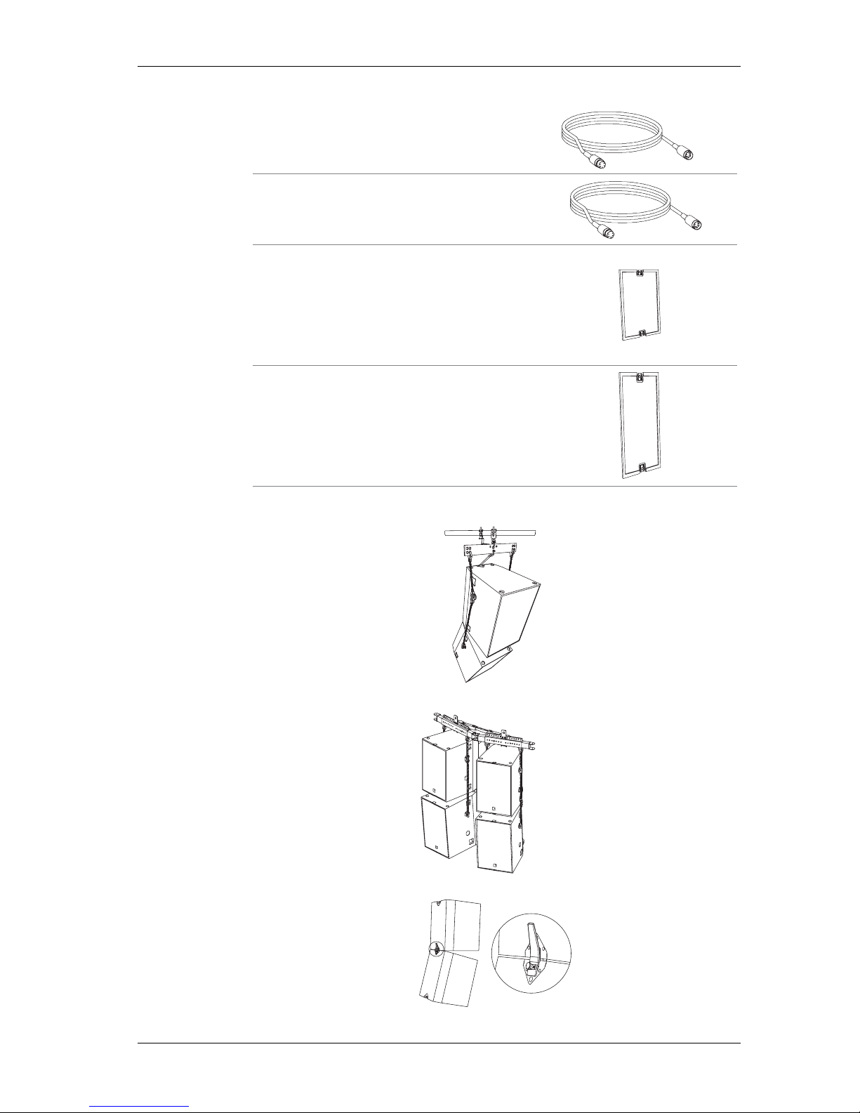
Operating Instructions ACCESS SYSTEM
KLING & FREITAG GMBH ©1995-2016 Version 6.2, 06.12.2016 Page 59 of 59
[2V]
[2W]
Transport cover ACCESS T5 / T9 / B5
colour: black[3F]
Transport cover ACCESS B10
colour: black[3G]
EP-5 loudspeaker cable 2,5
flexible PVC sheated cable, 4x 2,5 mm2, EP-5 male / female
colour: black
2m, 5m, 10m, 20m
EP-5 loudspeaker cable 4,0
flexible PVC sheated cable, 4x 4 mm2, EP-5 male / female
colour: black
2m, 5m, 10m, 20m
Applications:
Page 60

Operating Instructions ACCESS SYSTEM
KLING & FREITAG GMBH ©1995-2016 Version 6.2, 06.12.2016 Page 60 of 60
19. Regulations for Disposal
19.1 Germany:
It is not allowed to dispose of used electrical equipment as domestic waste.
But please do not dispose of them at official collecting points for recycling either!
All Kling & Freitag products are plain business-to-business (B2B) products. Disposal of
Kling & Freitag products labelled with a waste bin sign have thus to be disposed of by
Kling & Freitag alone. Please call Kling & Freitag at the number stated below if you have
a Kling & Freitag product to be disposed. We will offer you a straightforward and professional disposal not affecting costs.
If there is no dustbin sign on one of your Kling & Freitag products, because they have
been sold before March 2006 then by law the owner is in charge of the disposal. For
these we will be happy to assist and offer you proper ways of disposal.
Telephone number to call about the disposal of used Kling & Freitag products:
+49 (511)-96 99 7-0
Explanation:
With the ElektroG (law relating to electrical and electronic equipment and appliances)
we have complied with the EU-directive on waste electrical and electronic equipment
(WEEE, 2002/96/EC)
The Kling & Freitag AG has thus labelled all products mentioned in the WEEE from
03/24/2006 onwards with a sign with a crossed out waste bin and a white bar below.
This sign indicates that the disposal into the domestic waste is prohibited and that the
product has been put into circulation at the 03/24/2006 earliest.
The Kling & Freitag GmbH has been legally registered as a manufacturer with the registration office EAR. Our WEEE Registration-Nr. is: DE64110372
For the German Registration office EAR we have accredited that our products are sole
B2B products.
19.2 EU, Norway, Island, and Liechtenstein (not Germany):
It is not allowed to dispose of used electrical equipment as domestic waste.
The Kling & Freitag AG has thus labelled all products coming from EU-Member countries as well as Norway, Island and Liechtenstein (except Germany) mentioned in the
WEEE from 08/13/2005 onwards with a sign with a crossed out waste bin and a white
bar below. This sign indicates that the disposal into the domestic waste is prohibited
and that the product has been put into circulation at the 08/13/2005 earliest.
Unfortunately the European directive WEEE has been complied with implementing different national provisions of law throughout all member countries, which makes it impossible for us to offer consistent solutions for the disposal throughout Europe.
Responsible for complying with these provisions of law is the local distributor (importer)
of each country.
For proper disposition of used products in accordance with these local provisions in
the mentioned countries of the European Union (except Germany) please ask your
local dealer or the local authorities.
19.3 Other countries
For proper disposition of used products in accordance with local provisions in other
countries please ask your local dealer or the local authorities.
 Loading...