


wT 1207/11
1 Body
Only for DN 40, 50
Page 1
Mounting and operating instructions for
KLINGER
Piston valves series KVN DN 10 to 50 and
Regulating Piston valve KVRKN DN 10 to 50
with valve ring
Edition : 05/2001
Rev.: 03/2010
Fluid Control GmbH
Am Kanal 8-10
A-2352 Gumpoldskirchen/AUSTRIA
WKZ VI, VIII, Xc
″″″″
KX-GT
″″″″
2 Bonnet
3 Hand wheel
5 Lantern bush
6 Split screwed connection
7 Piston
8 Spindle
9 Valve ring KX-GT
10 Hexagon nut
11 Hexagon nut
12 Stud bolt
14 Belleville washer
16 Serrated lock washer
17 Disc
18 Threaded bush
19 Tension pin
21 Type-plate
Telefon:++43(0) 2252 / 600 0
Telefax:++43(0) 2252 / 63336
++43(0) 2252 / 600 - 242
office@klinger.kfc.at
e-mail:
WEB: www.klinger.kfc.at

wT 1207/11
Page 2
TABLE OF CONTENTS
Page 3 Overview of connection types
Page 4 Storage instructions
Page 5-6 Installation and commissioning instructions
Page 6 Operating instructions
Page 7 Information about dangerous operating errors.
and safety hazards
Page 8 - 10 Repair and restoration instructions
Page 11 Assembly figures
Page 12 Data sheet (torques)
Page 13 Spare parts code sheet
Page 14 Regulating piston valve KVRKN

wT 1207/11
Nominal
widths
:
KVN
DN 15
–
50 III, VI
″″″″
″″″″
KVMN
″″″″
″″″″
KVSN
DN 15
-
50 KVSN
See catalogue for fitting dimensions, pressure ratings, materials and application limits
Page 3
Overview of the various possible ways of connecting KLINGER PISTON VALVES
Type Designation:
DN 10 – 50 VIII, Xc
with weld-in ends
with weld-on ends
R 1/2
1/2
DN 1/2
″″″″
- 2
- 2
″″″″
NPT
- 2

wT 1207/11
Page 4
Storage instructions for KLINGER-PISTON VALVES and their spare parts
Valves and spares parts for valves may only be stored in dry storage rooms. Completely mounted
valves are to be stored in the „as–received“ condition (valve set to CLOSED position, connections
mould plugged). Spare parts for valves are to be handled with care, and should be kept in the original
packing furnished by the factory if possible during all storage.
If cover or shrink films are used, the appropriate measure must be taken to ensure that the atmosphere
inside the covers stays free of condensate water.
The appropriate protective measures are recommended for storage in dusty rooms.
To avoid confusion, all parts stored must be labeled as on the delivery note and stored in the correct
place.
Temperatures in the storeroom must not exceed the limit values of –20° C and +50° C and rapid
changes in temperature (causing condensation and perspiration) should be avoided.
Handling Regulations and Operating Instructions are supplied with, and should always be stored with
the products to ensure that important information and documents are appropriately passed on.
Corresponding documents are available for the identification of Klinger components ( spare parts code
sheet 13)
Our customers will be notified by circular letter of any modifications lying within the KLINGER domain
that affect storage requirements.
Damages owing to improper storage will release Klinger from any obligations as may be derived from
the warranty, guarantee and product liability.

wT 1207/11
Page 5
Installation and Commissioning Regulations for KLINGER PISTON VALVES
(KVN Series)
Please bear in mind the general hazard notes of Klinger valves ( see document wT2792.11....)
Klinger piston valves can be installed in any position in the piping system.
The preferred through flow direction (indicated by an arrow on the body) should, however, be observed.
Note: Before installation protective caps must be removed from both sides of valve body
Attention: Piston valves show a piston pump effect while closing. This can result in increased pressure
at the inlet side when used in the preferred flow direction. When used with piston pumps and
non-return valves, piston valves should therefore be installed opposed to the preferred
through flow direction (see Fig.1 below).
Fig. 1 Direction of flow
No special maintenance is required after commissioning valves with the KX-GT since the rings do not
set like conventional, soft-sealing valve rings.
For recommended tightening torques see Technical Data Sheet Page 12

wT 1207/11
Page 6
Klinger piston valves have a very high body strength, the usual attention must be directed to the axially
precise and parallel position of the connections on the system end.
The overall length of the Klinger piston valves with but weld ends was selected to allow welding in an
assembled condition (valve closed)
Klinger recommends to check the temperature development in the area of the valve ring seats for
piston valves with socked weld ends.
Note: If the line and valve are subsequently insulated, the insulation should only extend as far as the
head flange on the body side so that access to the bonnet hexagon nuts (Pos.10) is not impeded.
Since the valve body can remain in site for repairs and maintenance work, the valve insulation
does not need to be removable.
Klinger accepts no liability relating to guarantees, warranties, and product liability legislation for damage
caused by incorrect installation and failure to observe the commissioning regulations.
Operating Instructions for KLINGER PISTON VALVES (KVN series)
Klinger piston valves must be closed clockwise and opened anticlockwise.
When closing the valve the hand wheel should be turned until it adjoins on the bonnet. Unlike globe
valves, piston valves do not require increased final torque. Due to the design of piston valves, a seal
may be achieved before the closed position is reached. To protect the valve rings, piston valves must
always be closed as far as they will go.
As Klinger piston valves can also be used to regulate and to throttle, the above does not apply when
opening the valve or setting it to the open position for regulating or throttling purposes.
Through flow characteristics for valve throttle positions are available from Klinger on request.
If a valve starts leaking, check the tightening torques of the bonnet fastening nuts (10) referring to the
table on page 13 and tighten if necessary. For this the valve needs to be in CLOSED position.
Klinger accepts no liability relating to guarantees, warranties and product liability legislation for damage
caused by failure to observe the operating instructions.

wT 1207/11
Page 7
Recommended preventative maintenance to obtain the best possible service
life from KLINGER VALVES
As with all spindle-operated mechanisms, regular lubrication with Metaflux Lubricating Metal Paste
70-85 increases the life of the spindle (Pos8). In addition, the coupling moment will be decreased when
the spindle is well lubricated.
At temperatures above 50°C the spindle must be lubricated at least once a month or after 500
operations.
Especially the split screwed connection should be lubricated.
Hazardous Operating Errors and Possible Sources of Danger
Where the process fluid is incompressible, the operating of piston valves can cause pressure changes
in tightly sealed parts of the system. This should be taken into account especially during the planning
stage and can be avoided by selecting suitable installation positions (see Fig. 1).
Piston valves provide a particularly good seal. During temperature changes, process fluid captured
between two piston valves can cause considerable changes in pressure which may exceed the
pressure category of the valve. In such cases, appropriate volume compensation (expansion tank) is
necessary.
Always ensure that the correct tightening torque specified in the Technical Data Sheet on Page 12 is
applied to the bonnet hexagon nuts.
Do not loosen or undo these nuts while the valves are under pressure.
The valves must not be subjected to pressure shocks in excess of one and a half times their rated
pressure.
When the stem thread becomes so worn that its stability seems endangered, release the pressure on
the valve and carry out the necessary maintenance.
Valves made of cast iron are particularly susceptible to brittle fracture and impact damage. This should
be borne in mind when choosing materials.
Whatever the application, always consult the operating limits diagram (pressure-temperature) and also
consider the suitability of the materials for various process fluids.

wT 1207/11
Page 8
Maintenance and Repair Instructions for KLINGER PISTON VALVES
(KVN series)
Klinger piston valves are easy to repair using simple assembly and dismantling tools. The valve does
not have to be removed, but the line system must be depressurised and emptied.
We recommend the following procedure for dismantling:
• Depressurise and empty the system
• Open the valve fully
• Unscrew the bonnet fastening nuts (Pos.10),
• Turn the hand wheel (Pos.3) clockwise (closing direction) (bonnet rises out of body)
• Turn bonnet (Pos.2) slightly until the flange rests against the stud bolt face (Pos.12) and turn hand
wheel anti-clockwise (opening direction) until piston (Pos.7) is completely free of valve ring
(Pos.9), (see Fig.1)
• Remove bonnet together with hand wheel, and stem- set
• Remove upper valve ring (Pos.9) and lantern bush Fig.2*) using lantern bush extractor
• Remove bottom valve ring (Pos.9) with ring extractor hook Fig. 3*)
*) Be careful not to damage the bore of the valve body
• Clean the valve body bore and valve ring seat, if necessary with fine sandpaper
Note: Do not sandblast

wT 1207/11
Page 9
We recommend the following procedure for reassembly:
• Mount bottom valve ring using mounting tool (see Figure 4
*
) )
• Insert the cleaned lantern bush **)
• Assemble upper valve ring using mounting tool
Attention: Particular care should be taken to ensure that the rings are inserted correctly
positioned into the bore of the valve body using the mounting tool
*) Do not use lubricant or grease
**) Replace lantern bush ensuring that no teeth are on the valve outlet side (Kv valve optimisation)
Attention: Whenever the valve ring is replaced, always check at the same time that the
piston/stem/bonnet assembly is functioning properly. Check that: !!!
While doing so, check to see whether:
a) the outer cylinder surface of the piston and piston shaft is smooth and unmarked
b) the stem head moves freely in the two-part union piece
c) the trapezoid thread of the stem is not unduly worn, and
d) there is no excessive play between stem and threaded bush
If none of the above components needs replacing, lubricate the trapezoid thread and the neck of the
bonnet with a suitable lubricant, such as Metaflux Lubricating Metal Paste 70-85 before reassembling
the valve.
If any parts do need replacing, proceed as follows:
• Undo the hand wheel hexagon nut (Pos.11)
• Unscrew the stem (Pos.8) from the bonnet (Pos.2)
• Clamp the piston (Pos.7) in a vice
Attention: Imperatively use soft clamping jaws
• Unscrew the split nut (Pos 6)
Attention: Left thread !

wT 1207/11
Page 10
If the bonnet is provided with a threaded bush (Pos.18), proceed as follows:
• Tap the tension pin (Pos.19) out of the bonnet (inwards)
• Clamp the bonnet in the vice unscrew the threaded bush using spindle and hand wheel
(see Fig. 5)
• Screw the new threaded bush into the bonnet and pin them together *)
*) When renewing actuating parts, we recommend putting in a new spindle and threaded bush at
the same time
• Mount the spindle in the piston after thoroughly lubricating the spindle head with a suitable
lubricant (Metaflux Lubricating Metal Paste 70-85)
• Mount the spindle into the bonnet and install the hand wheel. Lubricate the bonnet neck and the
spindle with a suitable lubricant (Metaflux Lubricating Metal Paste 70-85)
Assembling body and bonnet unit
• Screw spindle with piston into bonnet
• Position bonnet on valve body, and screw nut by some turns
• Now close valve completely and open it again (when it opens, the bonnet with draws into the valve
body)
• Tighten nuts
• Close valve completely (turn hand wheel clockwise)
• Tighten bonnet hexagon nuts with torque wrench in diagonal order to specified torque.
For torque specifications, see Technical Data Sheet Page 12

wT 1207/11
Fig.1
Fig.2
Fig.3
Fig.4
Page 11

wT 1207/11
Fig.5
Page 12
Tightening - Torques
Notes upon Torques:
The values specified are guide values and apply to lubricated nuts and bolts.
With valves that have been in service a long time and already are worn-out on the sealing surfaces or,
in the case of gaseous medium where leakage is detected under high pressures, the tightening torque
can be increased by max.40 %.
stud bolt tightening Nm
DN dimension piece KX-GT TFM 1600
10/15 M 10 x 30 2 5 5
20 M 10 x 30 3 5 5
25 M 10 x 30 4 6 6
32 M 12 x 35 4 9 8
40 M 12 x 35 4 13,5 10
50 M 12 x 35 4 17 12
body - bonnet
wT 1207/11
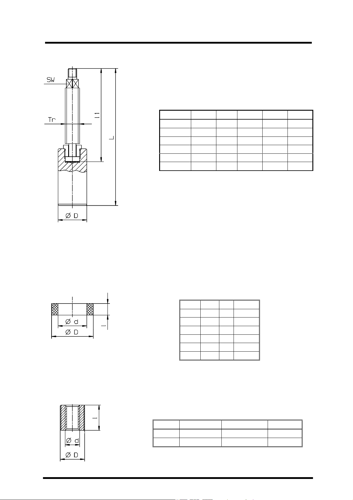
Piston set KVN
Threaded bush only for DN 40 and 50
–
VI
, VIII, Xc
upper
and lower Valve ring KX
-GT
Page 13
DN L l
1
SW Tr D
10/15 110 79 8 14 x 4 15
20 126 91 8 14 x 4 20
25 143 100 9,5 16x 4 25
32 160 112 11 20 x 4 30
40 190 129 12,5 20 x 4 40
50 218 149 14 22 x 5 50
DN D d l
10/15 23,5 15 8
20 30 20 9,3
25 38 25 10,6
32 45 30 14,6
40 58 40 14,6
50 70 50 16
DN D d l
40 M 34 x 1,5 Tr 20 x 4 35
50 M 34 x 1,5 Tr 22 x 5 40

wT 1207/11
For the rebuilding of a piston
Page 14
Operating instructions for the rebuilding of a piston valve Type KVN to
a regulating piston valve KVRKN
Klinger-regulating piston valves KVRKN are adjusted with a regulation piston . Therefore the throughflow direction is almost linear which facilitates the regulation of the media flow.
The sealing system correspond to the piston valve Principe .The Closing function can be applied same
as with the normal piston valve.
See catalogue for fitting dimensions, pressure ratings, materials and application limits .
valve KVN to a regulation
piston valve KVRKN please
refer to this KLINGER mounting
and operating instruction
wT1207/11
The piston KVN-standard has
to be replaced by a regulating
piston resp. a regulating piston
set.
After that the valve can be
assembled again according the
mounting instructions.
Stockage, mounting and
operation instructions are also
encluded in this wT1207/11
 Loading...