

Klingenburg AS2 User Manual
AS2 Cleaning Device for
Cleaning Rotary Heat Exchangers
ENERGY RECOVERY
Page 2
1. Cleaning Options
Page 3
2. Cleaning Device
Page 6
3. Cleaning Sensors
Page 10
4. AS2 Cleaning Control System
Page 16
5. Menu navigation
Page 23
6. Troubleshooting
Page 25
7. Technical Data
1. Cleaning options
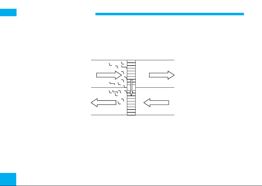
Self-cleaning effect
Under the usual conditions for the operation of ventilation systems and air conditioning systems, rotary heat
exchangers do not tend to become contaminated. This is due to the laminar airflow in the rotor mass and the
counter-current circuitry.
Counterflow Circuit:
Outside air
Supply air
Extract air
Air filtration before the rotor is only necessary for viscous, greasy and coarse contamination. As the self-cleaning effect occurs only when the rotor is rotating, idle rotors tend to become contaminated.
A cleaning cycle circuit offers a remedy here. The rotor mass is periodically rotated further in order to prevent
one-sided accumulation. This cleaning run cycle, also described as interval mode, is integrated in the rotor
control system (see control system description for the twist switch – latched controller).
2
Exhaust air
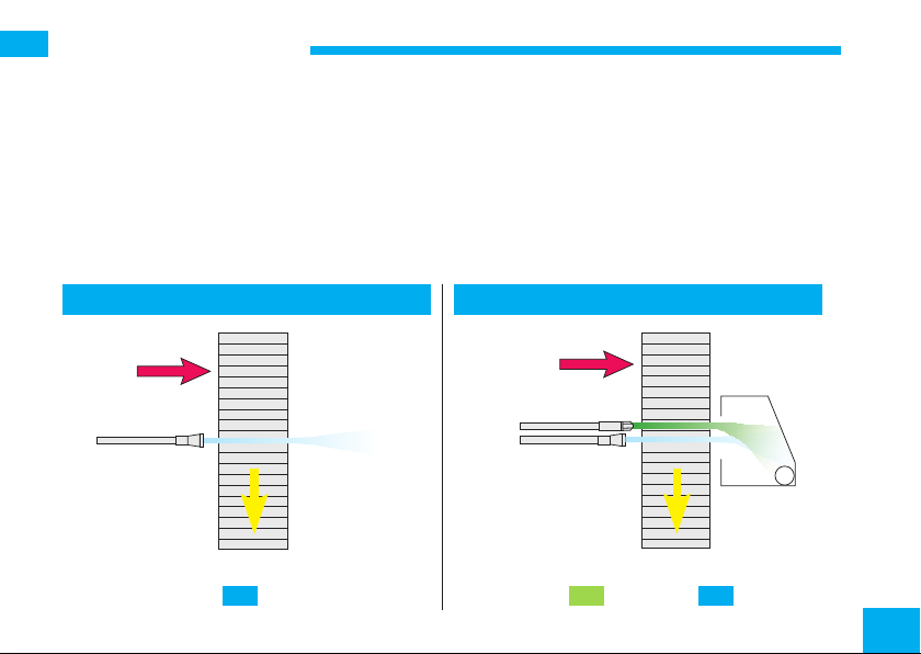
2. Cleaning device
If strongly adhesive contamination is present in the air, the installation of an automatic cleaning apparatus may
be sensible. Usually, blowing out with compressed air is sufficient.
Cleaning with high-pressure warm water is necessary only with tenacious viscous and greasy contamination.
Please note that the residual water is to be blown out of the rotor following cleaning.
For water purification, a compressed air nozzle is therefore always required.
Compressed air cleaning High-pressure warm water cleaning
Exhaust air
Exhaust air
Air
Air Water Air
Water
Air
3
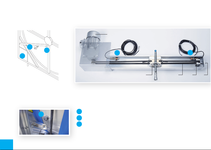
The slide is moved by an AC motor, and the power transmission is through a toothed belt.
Contactless proximity switches send an alert when the slide reaches either end position. Another proximity
switch is installed in the rotor casing and records the rotor speed.
1
B
C
A
* Sensors are installed on
the inside of the cleaning
track
A
A
4
B
C
2 543
A slide travels on a track over the radius of the rotor. The cleaning nozzles
for compressed air and possibly for water, depending on requirements, are
installed here.
A
Pulse sensor (for rotor speed) is located in the rotor casing
Rotor circumference sensor*
B
Rotor centre sensor*
C
(1) AS2 drive motor
(2) Nozzle slide
(3) Toothed belt
(4) Idler
(5) Clamping screw

Following each rotation of the rotor, the cleaning apparatus advances by the width of a nozzle stream. This
allows gap-free cleaning.
When the cleaning apparatus is switched off, the carriage is positioned on the periphery of the rotor. The
cleaning procedure can be started either by a built-in weekly time switch, by an external switch or by the Start
switch under the display.
Caution: Ensure that the heat exchanger wheel is released when starting cleaning and is turning for the whole
time the program is running. When the cleaning device is operating, the nozzle slide continuously travels to the
centre of the rotor. When the sensor reaches the centre, the air and possibly water cleaning begins.
A relay output for warm water and a compressed air valve are available. When the carriage reaches the
periphery of the rotor, the water valve relay falls and the rotor is dried with compressed air during the return
movement.
On reaching the centre sensor, the air relay switches off and the carriage travels to the starting position. During
the cleaning procedure, the rotor runs with variable speed under the control of the AS2 control system.
The external control signal (0 - 10 Volt) is not processed during the cleaning procedure, so this process should
be carried out during the idle times.
5
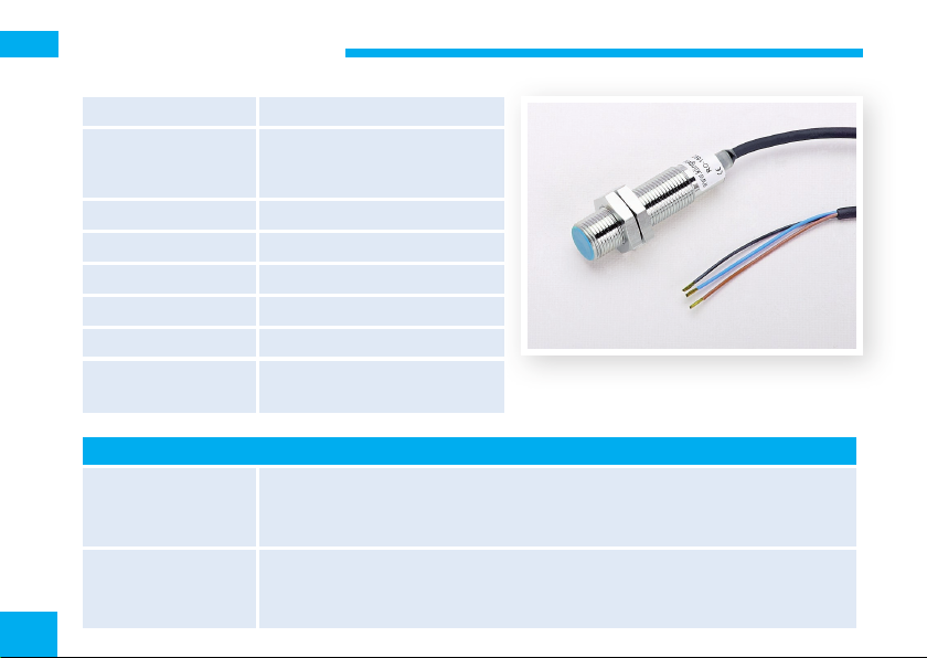
3. Cleaning Sensors
Manufacturer Klingenburg
Model
IP code IP67
Power supply 10-30 V=
Contact Magnet
Sensing distance <=30 mm
Connect. wire colours blue / brown / black
Usage Rotors Sorption wheel,
Connection to controller:
KR4/7
KR15 and Premium
KS 4/7/15
to cleaning device
AS2
6
MMG 120BDKX, PNP Switch
magnetic
Pulse sensor cleaning device
Clamp 4 = blue; Clamp 5 = brown; Clamp 6 = black
Clamp 6 = blue; Clamp 7 = brown; Clamp 8 = black
Clamp 4 = blue; Clamp 5 = brown; Clamp 6 = black
+Ub = brown
Sensor Pulse Tkt = black
GND = blue
Klingenburg Secatec
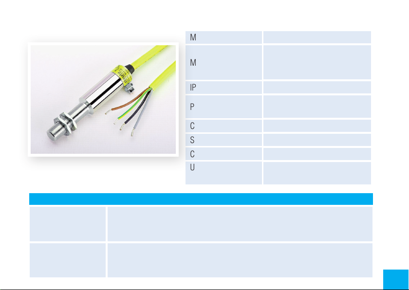
Steute
Connection to controller:
KR4/7
KR15, Premium
KS 4/7/15
to cleaning device
AS2
Manufacturer Steute
Model
IP code IP67 Atex
Power supply
Contact Magnet
Sensing distance <=7 mm
Connect. wire colours gr-yel / grey / brown / black
Usage Rotor, End position switch slide,
Clamp 5 = brown; Clamp 6 = black
Clamp 7 = brown; Clamp 8 = black
Clamp 5 = brown; Clamp 6 = black
+Ub = brown; Sensor centre Mit = black
Sensor circumference = black
Sensor pulse Tkt = black
EEX-RC-M 14W
Chanceover contact
Reed contact
changeover contact up to 250V
AC/DC
pulse sensor cleaning device
7
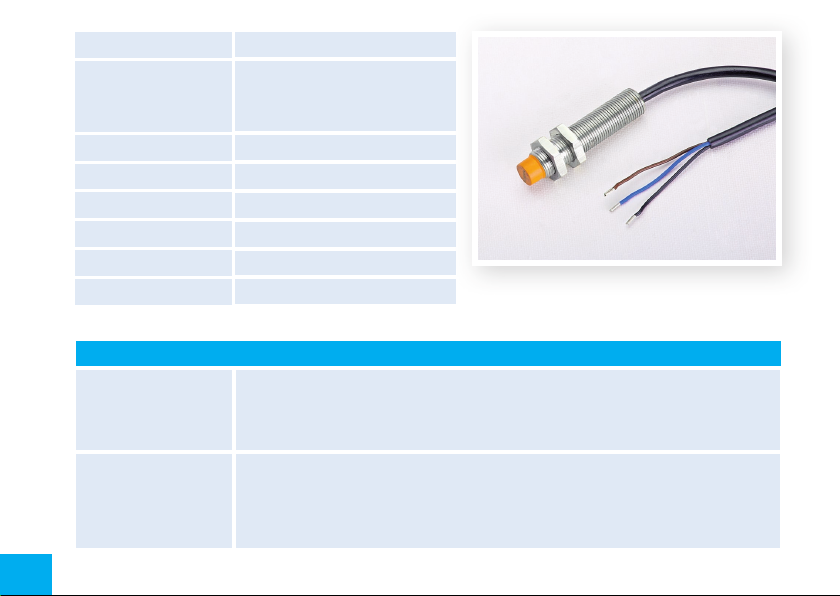
Manufacturer Schmersal
IFL-N4-12-10P
Model
PNP N/O
Inductively
IP code IP67
Power supply 10-30 Volt =
Contact Steel contact tabs
Sensing distance <=3 mm
Connect. wire colours blue / brown / black
Usage Cleaning device standard
Connection to controller
KR4/7
KR15 and Premium
KS 4/7/15
clamp 4 = blue; clamp 5 = brown; clamp 6 = black
clamp 6 = blue; clamp 7 = brown; clamp 8 = black
clamp 4 = blue; clamp 5 = brown; clamp 6 = black
Schmersal
to cleaning device
AS2
8
+Ub = brown
Sensor centre Mit = black
Sensor circumference Umf = black
GND = blue
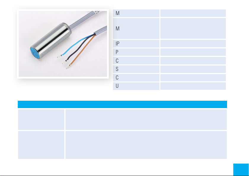
Pepperl & Fuchs
Connection to controller
KR4/7
KR 15 and Premium
KS 4/7/15
to cleaning device
AS2
Manufacturer Pepperl & Fuchs
NBB 8-18GM50-E2-3G-3D
Model
PNP N/O
Inductively
IP code IP67Atex
Power supply 10-30 Volt=
Contact Steel contact tabs
Sensing distance <=7 mm
Connect. wire colours blue / brown / black
Usage ATEX cleaning decice, Rotors
clamp 4 = blue; clamp 5 = brown; clamp 6 = black
clamp 6 = blue clamp 7 = brown; clamp 8 = black
clamp 4 = blue; clamp 5 = brown; clamp 6 = black
+Ub = brown
sensor centre Mit = black; sensor circumference Umf = black
sensor pulse Tkt = black
GND = blue
9

4. AS2 Cleaning Control System
Functional characteristics
Processor-controlled monitoring of the cleaning sequence
Coloured display
Detailed error messages
Menu navigation
Cleaning takes place from the inside to the outside
(the contaminated water runs towards the outside)
10
 Loading...