

K-Line SPEEDTILLER 2940U, SPEEDTILLER 2925U, SPEEDTILLER 2930U, SPEEDTILLER 2935U, SPEEDTILLER 2918U Operating Manual

OPERATING MANUAL
2918U- Shown
2918U
SPEEDTILLER®
2900 3 Point Linkage
Folding Wing, Non-Folding Wing
Universal Model
Serial No.

K-Line Ag ©
_______________________________________ ___________

K-Line Ag ©
Introduction
1
First Start-up
19
Identifying the machine
2
What do you need your Speedtiller® to do?
19
Tractor requirements
2
Problem Solving
20
Definitions used in this manual
2
Daily Maintenance
21
Safety Alert
3
To convert from Trailing mode to 3PL mode
22
Safety Alert Symbol
3
To convert from 3PL mode to Trailing mode
22
Signal words
3
Performing maintenance
23
Your Safety & the Safety of other Persons is
Important
4
Priming Hydraulic System
24
Safety sign locations
5
Lubrication of rear Roller bearings
24
Safety Decals
6
Tire Safety and Pressures
24
Safety sign care
8
Attaching jump arm to machine
25
To order Safety Decals
8
Standard Rear Roller bearing assembly
26
How to Install Safety Decals
8
Exploded view of disc arm bearing
27
Safe Operation
8
Exploded view of side coulter
28
Hitching and Un-hitching
9
Magna-Lite Wiring Harness Schematic
29
Hydraulic Hose hook-up
10
Bolt torque table Imperial
30
Electrical connection hook-up
10
Bolt torque table metric
31
Wheel transport safety locks
11
Speedtiller® Specifications
32
Transporting/Roading
11
Risk Management
34
Power lines can arc and electrocute
12
K-Line Agriculture risk assessment
36
Hydraulic System Failure
13
Warranty
37
Machine Operation
14
Warranty registration form
39
Setting & Adjustments
14
Warranty Request form
41
Speed Range
14
Depth control
15
Fore and Aft level (tilt) & correct tracking
15
Front disc gang lateral positioning sideways
adjustment
17
Side coulter adjustment
18
_______________________________________ ___________
Table of Contents
K-Line Ag has produced this manual as a guide for the operation of your machine.
While every care and precaution has been taken in compiling this booklet, K-Line Ag carries no responsibility for
errors and omissions.
This production is made available as is, without warranty of any kind expressed or implied.
K-Line Ag assumes no responsibility for damages resulting from the use of information contained herein.
This booklet is compiled to comply with the present state of the machine at the time of publication, and K-
Line Ag reserves the right to improve and revise their products at any time

K-Line Ag ©
_______________________________________ ___________

K-Line Ag ©
_______________________________________ ___________
Dear Customer
Thank you for purchasing a 2900 Three Point Linkage Universal Speedtiller®. We would
like to assure you that you have made a good choice, and will be able to rely on this
high quality piece of equipment. We ask you to follow the user’s instructions closely, as
this will ensure that you experience the benefits of using the machine without
experiencing the unnecessary down time caused by misuse.
When you receive the machine, make sure that it has not been damaged during
transportation and that no parts are missing. Contact your dealer immediately if any
parts are missing. Ensure that all components are correctly adjusted.
The return of the Warranty Registration Form (Page 41) will enable a prompt and
efficient identification of your 2900 Three Point Linkage Universal Speedtiller® and
attention to any concern you may have.
Before operating PLEASE TAKE THE TIME TO LEARN the process of operation. Do
not take the unit for granted; ease into becoming familiar with your new equipment. The
operator should be a responsible adult familiar with farm machinery and trained for this
purpose. Do NOT allow persons to operate or assemble the unit until they have read
this manual and understand how to use this machine, and observe the safety
precautions.
Never exceed the limits of this machine. If its ability to do a job, or to do so safely, is in
question - DO NOT TRY IT.
DO NOT attempt to operate this equipment under the influence of drugs or alcohol.
Remember - Your best assurance against accidents is a careful and responsible
operator.
If you have any questions not answered in this manual or require additional copies or
the manual is damaged, please contact your dealer or be free to Phone us on our Free
call Number: USA - 1800 445 6882 AUS - 1800 194 131
The team here at K-Line Agriculture trust you enjoy a good season and prove the
benefits of owning and operating a quality machine that is built to perform.
Signed:
James Larsen
General Manager
Page | 1
K-Line Ag ©
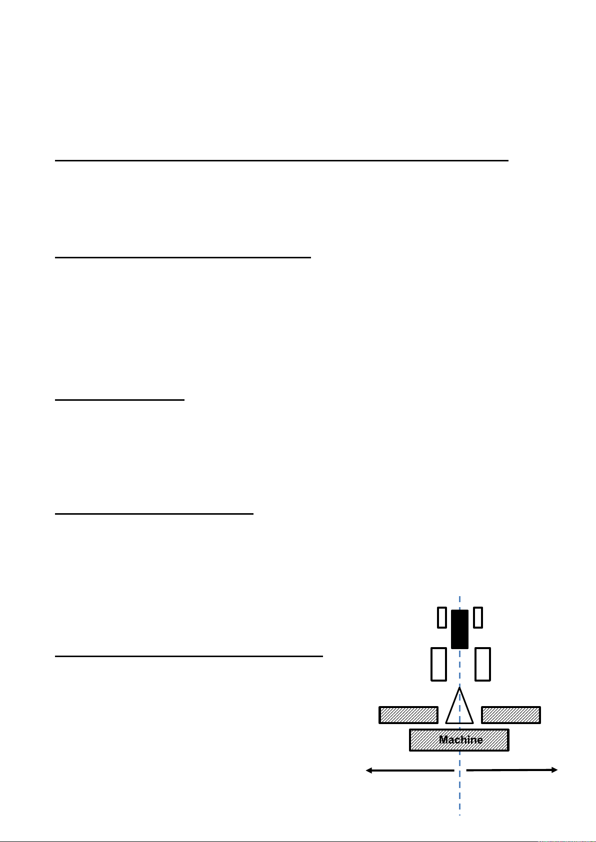
Left
Right
Hand
Hand
_______________________________________ ___________
IDENTIFYING THE MACHINE FOR REQUESTING SPARE PARTS
The machine is identified by the serial number on the metal plate on the machine. When
requesting spare parts or maintenance service, please indicate the model and number
of your equipment to ensure prompt and efficient attention.
AVAILABILITY OF GENUINE PARTS
K-Line spare parts and accessories have been specifically designed and developed for
the machines produced. We would call your attention to the fact that non-genuine parts
and accessories are not recommended by K-Line. The use of such replacement parts
frees K-Line from all liability and makes the warranty void. The installation and/or use of
non-genuine parts may, because of technical characteristics of construction, may modify
or influence the performance of the machine negatively.
AFTER DELIVERY
When you receive the machine, make sure that it has not been damaged during
transportation and that no parts are missing. Only by giving us immediate advice can the
necessary replacement parts be obtained. Ensure that all components are correctly
adjusted.
TRACTOR REQUIREMENTS
10-14 Horsepower x width of machine in feet
25-35 kilowatt x meter width of machine in meters
Check the tractor manufacturer specifications for weight and suitability of rear
mounted implements
1 x double spool
Hydraulic operating pressure 2800 PSI / 19000 KPA
DEFINITIONS USED IN THIS MANUAL
Page | 2
Side
Side

K-Line Ag ©
Be Familiar with Safety Decals
Read and thoroughly understand all
the ‘Safety Decals” on (Pages 8 &
9) and throughout this manual.
Safety Alert
___________________________________________________________________
Safety Alert!!
Safety…You Can Live With It
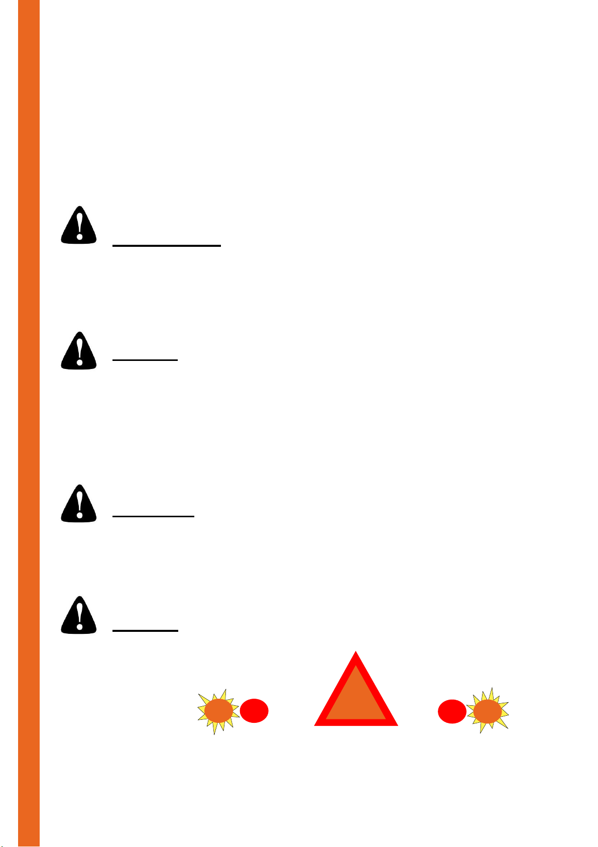
SAFETY ALERT SYMBOL
When you see this symbol, you must be
alert to the possibility of injury or death.
SIGNAL WORDS
The use of signal words DANGER, WARNING and CAUTION relating to the safety
messages. The appropriate Signal Word is selected using the following guidelines.
DANGER: indicates an imminently
hazardous situation that, if not avoided,
WILL result in serious injury or death if
proper safety measures are not taken.
WARNING: Indicates a potentially
hazardous situation that, if not avoided
COULD result in serious injury or death if
proper safety measures are not taken.
CAUTION: Indicates a potentially
hazardous situation that, if not avoided
MAY result in serious injury or death if
proper safety measures are not taken.
IT IS THE RESPONSIBILITY OF THE USER TO MAINTAIN IN AS NEW CONDITION
ALL SAFETY SIGNS AND DEVICES USED ON THIS MACHINE. FAILURE TO
OBSERVE THE INSTRUCTIONS OF THIS BOOKLET COULD RESULT IN SERIOUS
INJURY OR DEATH.
Page | 3
K-Line Ag ©
Safety Alert
___________________________________________________________________
Your safety and the safety of
other persons is important!
BE PREPARED
Wear suitable clothing – loose clothing is dangerous
Use hearing protection – loud noises can cause deafness
Use gloves and eye protection – high pressure fluids are dangerous. Release
pressure from hydraulic lines before disconnecting
BE SAFE
Attach safety chains to towing unit
Only operate machine from tractor seat
No riders on machine
Keep body well clear – machine components can suddenly move or fall
Shut down tractor while making adjustments
Do not exceed speed limit 20 mph (32 km/h) – UNBRAKED MACHINE
For road travel conform with All federal, state and local authority requirements
BE AWARE
Pay full attention to your task – distractions while operating machinery are
extremely dangerous
Check for overhead power lines
Keep clear of escaping high pressure fluid which can penetrate the eyes and skin
BE SEEN
Use approved safety signs and lighting
Page | 4
K-Line Ag ©
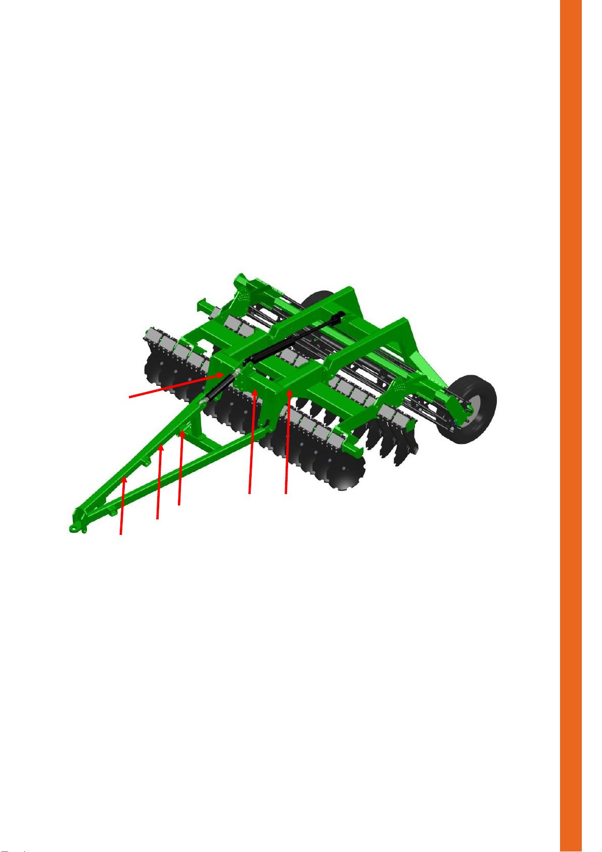
Figure 1
Safety Alert
H
A J K
C
G
___________________________________________________________________
Safety Sign Locations
Familiarise yourself with the safety sign location and type of warning for safety
awareness!
IMPORTANT
If safety signs have been damaged, removed, become illegible or parts replaced without
decals, new decals must be applied. New decals are available from your authorised
dealer or direct from factory.
Page | 5
K-Line Ag ©
A.
B.
C.
E.
G.
D.
F.
Safety Alert
___________________________________________________________________
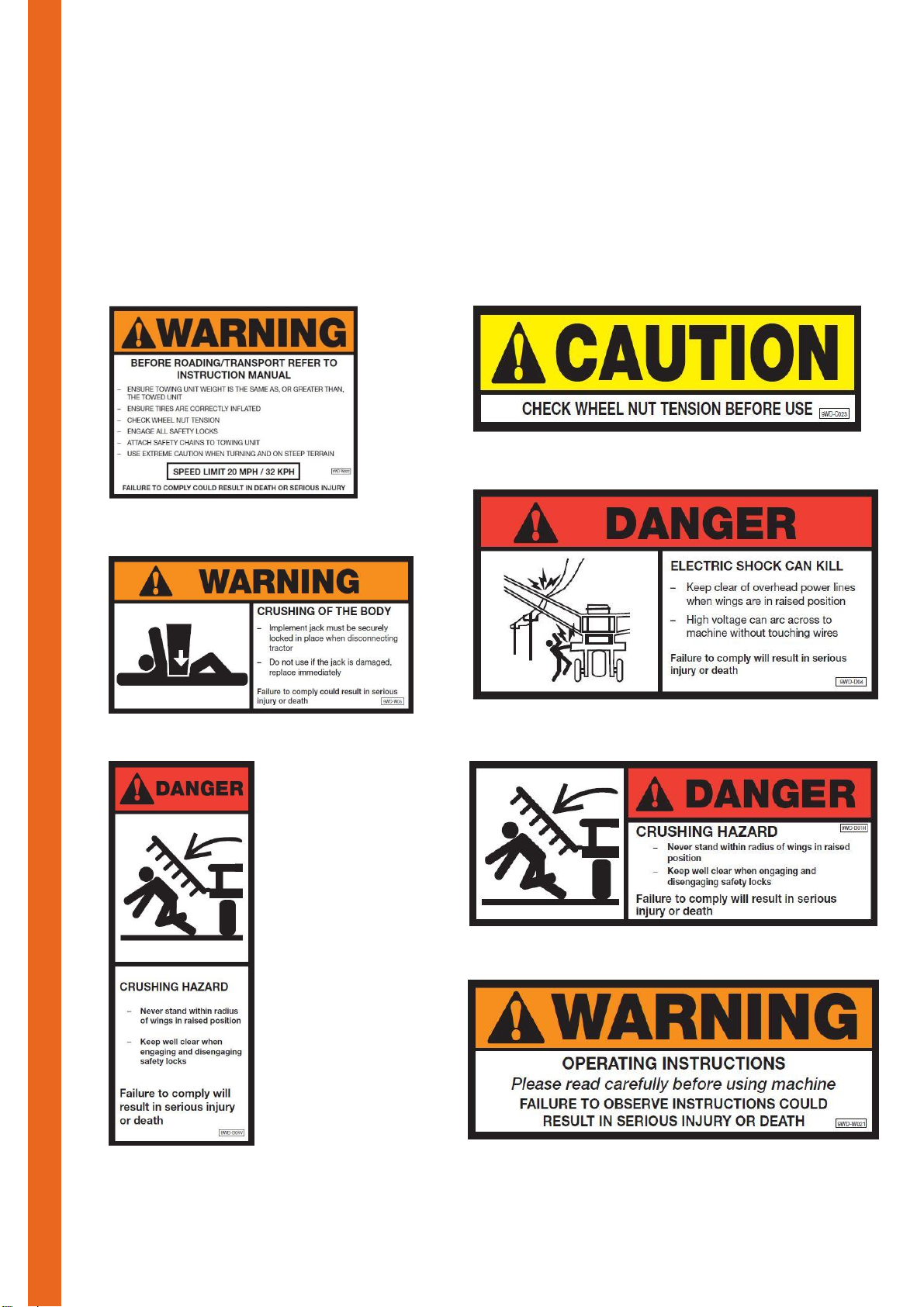
SAFETY DECALS
TO REORDER FREE CALL AUS- 1800 194 131
USA- 1800 556 6882
(Re-order according to part numbers shown below)
*Affixed on every wheel
Page | 6

K-Line Ag ©
Decal
Part Number
A.
9WD-W022
B.
9WD-C023
C.
9WD-W05
D.
9WD-D04
E.
9WD-D01V
F.
9WD-D01H
G.
9WD-W021
H.
9WD-C04
I.
9WD-I01
J.
9WDW-T5
K.
9WDD-T3
L.
9WD-W024
M.
9WD-W10
N.
9WD-W01
H.
J.
I.
K.
L.
M.
Safety Alert
N.
___________________________________________________________________
Page | 7
K-Line Ag ©
Figure 2
Safety Alert
Australia: K-Line Agriculture
PO Box 340
74 Young Rd
Cowra NSW 2794
Email: sales@k-line.net.au
Freecall: 1800 194 131
___________________________________________________________________
Safety Sign Care
Keep safety signs clean and legible at all times
Replace safety signs that are missing or have become illegible
Replaced parts that displayed a safety sign should also display the current sign.
To order Safety Decals contact:
USA: K-Line Agriculture
PO Box 567
700 Division Avenue S
Cavalier ND 58220
Email: sales@k-lineag.com
Freecall: 1800 445 6882
How to Install Safety Signs:
Be sure that the installation area is clean and dry.
Decide on the exact position before you remove the backing paper.
Remove the smallest portion of the split backing paper.
Align the decal over the specified area and carefully press the small portion with the
exposed sticky backing in place.
Slowly peel back the remaining paper and carefully smooth the remaining portion of
the decal in place.
Safe Operation In field and
Transport/Roading
Read and understand your manual
Take time to familiarize yourself with the operation of
this machine, particularly the safety signs and
devices fitted to this machine.
good serviceable condition. Failure to heed may result in serious personal injury or
death. Escaping hydraulic fluid under pressure can penetrate the skin causing serious
injury. Avoid the hazard by relieving the pressure before disconnecting lines or
performing work on the system. Make sure hydraulic fluid connections are tight and all
hydraulic hoses and lines are in good condition before applying pressure to the system.
Use a piece of paper or cardboard, NOT BODY PARTS, to check for suspected leaks.
Wear protective gloves and safety glasses or goggles when working with hydraulic
systems. DO NOT DELAY! If an accident occurs, see a doctor familiar with this type of
injury immediately. Any fluid injected into the skin or eyes must be treated within a few
hours or gangrene may result.
Page | 8
Hydraulic fluid escaping under pressure can have sufficient
force to cause injury. Keep all hoses and connections in
K-Line Ag ©
OIL under high pressure COULD result in
serious injury or death
Figure 4
Figure 3
Safe Operation
___________________________________________________________________
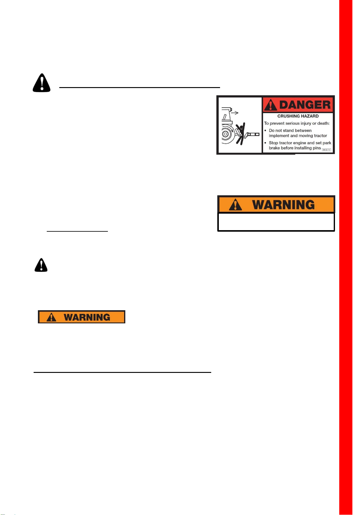
Hitching and Un-hitching (3PL) Mode
1. Keep well clear when backing up to machine. (see
figure 3)
2. Shut down tractor.
3. Secure all 3 Point Linkage safety locks & lock
drawbar pin in place.
4. Lock up 3 Point Linkage anti sway stabiliser system
on tractor.
5. Both Linkage arms must be set level
6. Plug in electrical lead to tractor connection (if
provided)
Hydraulic models
1. Clean all hydraulic couplings.
2. Hoses are coded according to function. (Page 10)
3. Beware of high pressure fluid. (see figure 4)
4. Release pressure from system before disconnecting.
5. Plug in hoses to respective remote ports.
6. Check hydraulic cylinders are fully primed to avoid
serious injury or death. (Page 10) for priming hydraulic
system
Hitching and Un-hitching (Trailing Mode)
1. Keep well clear when backing up to machine. (see
figure 3)
2. Shut down tractor.
3. Secure & lock drawbar pin in place.
4. Install safety chain by crossing the chains under the
tongue and secure to the drawbar hitch frame of the
tractor.
5. Clean all hydraulic couplings.
Page | 9

K-Line Ag ©
Extend
Retract
Hose Grip color codes
Color
Function
Red
Wheel lift
Figure 8
Figure 7
Figure 6
Figure 5
Safe Operation
Figure 9
___________________________________________________________________
6. Hoses are coded according to function. (Page 10)
7. Check tire pressure and wheel tension
8. Beware of high pressure fluid. (see figure 6)
9. Release pressure from system before
disconnecting.
10. Plug in hoses to respective remote ports.
11. Plug in electrical lead to tractor connection
12. Release implement jack & store
13. Jack must be securely locked in place when
disconnecting.
If implement jack is damaged DO NOT USE, replace
immediately, or severe bodily harm may result. See Figure
7.
14. Check hydraulic cylinders are fully primed to avoid
serious injury or death. (Page 24) for priming
hydraulic system
Hydraulic Hose Hook up (Accessory)
For ease of hook up, hose grip handles
are color coded.
The same color is used for both hoses on
each circuit
To distinguish between EXTEND and
RETRACT grips are marked according
to Figure 8
Electrical Connection Hook up
(Accessory)
Ensure tractor and machine electrical connections are compatible
Plug lead into tractor terminal
Test lighting prior to road travel (power not required for field work)
Page | 10

K-Line Ag ©
Figure 11
Sway Hazard:
IN DEATH OR SERIOUS INJURY.
Figure 10
Lift cylinder
Safe Operation
Figure 12
___________________________________________________________________
Wheel Lift safety locks
Lift cylinder lock channel type. (See figure 10)
Fully extend lift cylinder/s
Remove from storage point
Secure lock channel on cylinder/s shaft, with
lynch pins provided.
To release lock channel from cylinder/s, lift
hydraulics
When not in use always place lock channel
in storage point provided.
Transporting/Roading 3PL Mode
1. Check the tractor manufacturer specifications
for weight and suitability of rear mounted
implements
2. lock up 3 Point Linkage anti sway stabiliser
safety lock
channel
system on tractor
3. Ensure tractor tires are correctly inflated
4. Ensure safety locks and pins are engaged.
5. Keep brake pedals latched together at all times
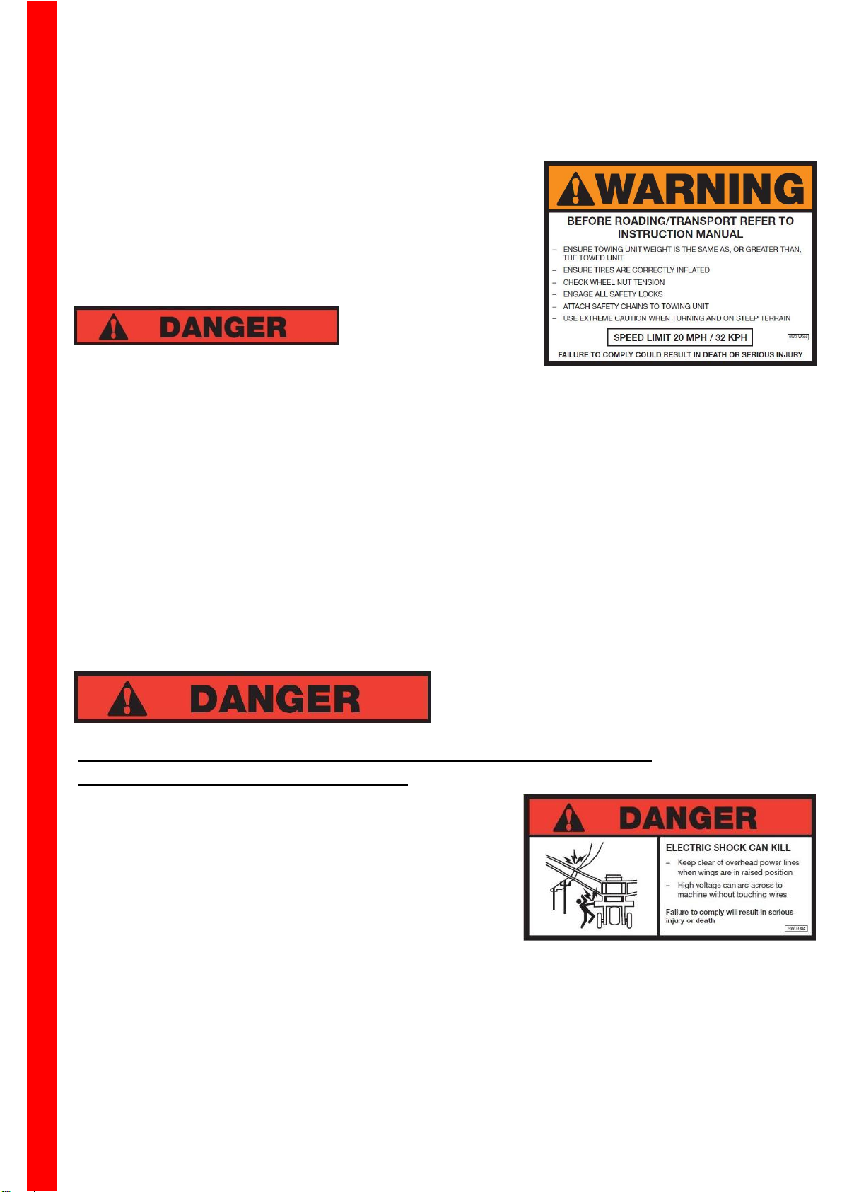
6. Plan your route to avoid heavy traffic
7. Observe bridge load ratings
Transporting/Roading Trailing Mode
8. Ensure towing unit weight is the same as or greater
than the towed unit.
9. Lockout tractor drawbar swing mechanism
10. Ensure tires are inflated to see page 25
11. Check wheel nut tension see page 25
*NB(see page 25 for wheel nut re-tensioning
sequence).
Lock out draw bar swing mechanism.
FAILURE TO COMPLY COULD RESULT
12. Ensure safety locks are engaged
13. Ensure safety chains are attached to towing unit.
Page | 11
K-Line Ag ©
Figure 14
Figure 13
Safe Operation
___________________________________________________________________
14. Drawbar must be in fixed position, not swinging.
(figure 13)
15. Keep brake pedals latched together at all times
16. Plan your route to avoid heavy traffic
17. Observe bridge load ratings
TIP OVER HAZARD this is an unbraked implement. Use
extreme caution when turning and on steep terrain.
Maximum towing speed is 20mph (32km/hr).
DO NOT EXCEED AT ANY TIME.
(figure 13)
Never transport machine on public roads
without complying with Federal and State laws
and local regulations governing the safe
movement of farm machinery.
Comply with state law warning light regulations.
POWER LINES CAN ARC AND ELECTROCUTE WITHOUT
COMING IN DIRECT CONTACT!!!
Consult electricity authorities and all relevant energy
companies to determine safe working distances from
overhead power lines etc. BEFORE operation of this
machine.
Ensure all operators are familiar with this manual
and all safety devices and features of the
machine.
Take every reasonable precaution as is
commonly expected in this industry and in the
operation of the machine.
Maintain the machine at all times in a condition
that is safe to operate, and ensure it complies
with any relevant safety acts of parliament,
government authorities and regulations.
Page | 12

K-Line Ag ©
Safe Operation
___________________________________________________________________
In the event of hydraulic system failure or hydraulic hose rupture,
you must follow the steps set out below.
Escaping Hydraulic fluid is dangerous and can cause serious injury or death.
Step 1: Prepare for shutdown.
Immediately return hydraulic leaver to neutral position.
Stop operating machine.
Step 2: Shutdown the equipment.
Use hydraulic leaver to lower machine to ground (if in raised position).
Step 3: Isolate the equipment.
Freely operate remote levers to release residual pressure from system.
If tractor so equipped place levers in float position.
Shut down tractor
Step 4: Apply the lockout / tagout device.
Disconnect all hydraulic hoses from tractor remotes.
Place lockout or out of service tags on all hoses.
Step 5: Control the stored energy.
Ensure no hydraulic pressure remains in system, slowly release bleed tap (if
equipped), or slightly loosen one hydraulic connection on each circuit to allow
any remaining fluid under pressure to be released.
Step 6: Verify isolation of equipment.
Double check the steps and verify that the equipment has been shut down and has
the lock and tag labels evident. Have repairs carried out and defective parts
replaced. Do not re-connect to tractor or other hydraulic power source, until system
has been fully tested.
Page | 13

K-Line Ag ©
Depth Control
Regulates depth via rear roller
Fore & Aft Tilt
Controls Tracking in line and
affects ground disturbance.
Front Disc Gang
Lateral positioning
Controls ground disturbance.
Side Coulter
adjustment
Controls furrow filling and levelling.
Four Main Adjustments
Machine Adjustments
___________________________________________________________________
MACHINE OPERATION
The Speedtiller® is a high performer in a wide range of conditions, but you will need to
know how to set up your new machine to gain the full benefits.
Adjustments
Tables
First Start-Up –
What do you need your Speedtiller® to do? -
Problem Solving-
SETTINGS & ADJUSTMENTS
Support machine on suitable jack stands or,
Lower machine to ground level.
Shut down engine.
Speed range
5-9 mph (8-15 km/hr).
Speed variable to suit conditions.
Greater activity occurs at higher speeds.
Before adjusting in the field YOU MUST:
Page | 14

To work deeper adjust roller upwards.
Insert pin in
requirement
Figure 15
Machine Adjustments
Fore and Aft
tilt adjuster
Figure 16
To work shallower adjust roller downwards.
For initial depth setting start shallow.
Operate machine for short distance and stop.
Adjust depth control in small increments to
Ensure both wing modules operate at same
Fore and Aft or tilt level affects how machine
tracks, straight tracking in line gives superior
ground disturbance, better trash flow and more even
disc wear.
In general, start with front row of discs working ¾”
(20mm) higher than back row of discs.
After initial setting run machine at normal operating
speed and stop.
Stand behind machine to check if machine is tracking
correctly. If adjustment is needed see figure 16
To adjust Fore and Aft Tilt (Trailing mode)
Rotate tilt adjustment to suit and lock See figure….
After initial setting run machine at normal operating
speed and stop.
Stand behind machine to check if machine is tracking
correctly. If adjustment is needed follow figures 17 &
18 on following page
To adjust Fore and Aft Tilt (Linkage mode)
K-Line Ag ©
___________________________________________________________________
Depth Control
Rear roller controls depth,
achieve required depth.
depth. (folding wing models)
hole
according to
depth
Fore and Aft, Tilt & tracking in line
IMPORTANT
To adjust Fore and Aft Tilt (Trailing mode)
See Page 16 to adjust for correct tracking in line
Turn top link to adjust
Page | 15

K-Line Ag ©
Tracking to the left
Lower front of module or machine
Tracking to the Right
Lift front of module or machine
Figure 18
Figure 17
*NB Ensure both wing modules are the same depth
Rear module tilt has greater effect on the tracking
in line
Right
Hand Side
Left
Hand Side
Left
Right
Hand Side
Hand Side
Left
Right
Hand Side
Hand Side
Machine Adjustments
___________________________________________________________________
*NB for tracking in line both wing modules must be
set at the same depth (folding wing models)
Page | 16

K-Line Ag ©
B
Direction of travel
Figure 19 Top View
A
A
Adjustable
Move front
Move front
B.
Ridge
Figure 20 Rear View
Adjust so the
Adjustable
Front Gang
Fixed
A
Machine Adjustments
___________________________________________________________________
Front Disc Gang Lateral Positioning
*NB- Be sure machine is tracking in line before attempting to make this adjustment page 19-
20.
The Disc positioning system is used for maximum
soil disturbance and reduced ridging. Adjustment can
be made for more precise weed control, soil
disturbance and to compensate for disc wear.
Start with factory settings
Test run at normal operating speed and stop
quickly.
Check for ridges of undug soil. (follow ridge into
machine)
For ridges where front and rear discs throw away
from each other see figure 19 at point (A), front
gang should be adjusted to the right. Figure 20
shows correct adjustment to remove ridge.
For ridges where front and rear discs throw
towards each other see figure 19 at point (B),
front gang should be adjusted to the left.
Only adjust in small increments ½” or 12mm
Re-check in hard soils as jump arms tend to flex
more.
Remember, Full ground disturbance starts at 2
½” 60mm
gang left to
remove
ridges at
Front Gang
gang right to
remove
ridges at A.
See figure 20
Page | 17
discs on
Rear
Gang
rear disc cuts
just down on
the side of the
front disc cut
discs on

K-Line Ag ©
Height adjustment
Fore & Aft
adjustment
Angle
adjustment
Slide adjuster
linkage
Right
Left
Slide
Bolts
Figure 21
Figure 22
Machine Adjustments
___________________________________________________________________
To Adjust Lateral disc gang position
Loosen main retaining bolts on slide mechanism
(See Figure 21)
Turn slide adjusting linkage to adjust to right or
left (see figure 21)
Lock slide adjusting linkage and tighten main
retaining bolts (380ft lb / 500nm)
Side Coulter Adjustment
Series of holes are provided for height adjustment –
(see Figure 22)
Adjust coulter on left hand side of module for
optimum furrow filling.
For excessive trash conditions
Move coulter forward and angle outwards
Raise coulter.
Move coulter to the outside of supporting angle
for more clearance.
setting
Page | 18
K-Line Ag ©
Comments
Pg
Before starting
Set machine on level surface
Ensure both Tractor 3 Point
Linkage arms are correctly
adjusted for level working.
Adjust roller 1” or 25mm above
surface.
Preliminarily adjust tilt
approximately ¾” or 20mm higher
at front.
Run at operating speed & check
adjustments in this order.
Tracking in line.
Lateral front disc adjustment
Depth (adjust deeper gradually).
Side coulter setting
15
15/16
15/16
17
15
18
Comments
Pg
Mulch in trash for humus
building
Shallower and faster better for
mulching.
Shallower gives more trash flow.
May have to go slower if trash
content is heavy.
Adjust side coulter if necessary
15
18
Full ground disturbance for
better weed control, trash
flow & seed bed
preparation.
Pay Specific attention to settings &
operating conditions
Full ground disturbance starts at 2
½” 60mm
Cross working 15° off line is best to
level soil and give better trash flow.
Soil moisture & conditions.
What do you need your Speedtiller® to do?
First Start-up
Machine Adjustments
___________________________________________________________________
Page | 19
K-Line Ag ©
Depth setting- ensure both wing
modules are the same depth. This
can affect tracking in line.
Tracking in line (tilt)
Lateral disc gang adjustment.
Side coulter settings.
15
15/16
17/18
18
Work Soil Deeper
Gradually lower depth settings.
Slower operating speed.
15
14
Comments
Pg
Need more disturbance &
weed control
Check these adjustments in sequence-
Tracking in line.
Lateral disc gang adjustment.
Lower depth control settings
(gradually).
15/16
17/18
15
Machine Blocking in loose
soil with heavy trash
Work at an angle 15° off line.
Lift front disc gang to work
shallower, ensuring rear disc gang
is operating deep enough to drive in
the soil.
Slow down to allow time for trash to
move through machine.
Adjust side coulter (common reason
for blockage).
Coulter Adjustment alternatives-
Lift up.
Move forward.
Angle coulter outwards.
Move coulter to outside of support
member to give better to give better
clearance for trash flow.
18
18
Plugging in Wet Soils
Raise working depth
Increase speed
Give soil more time to dry out.
15
Problem Solving
Cont…
Machine Adjustments
___________________________________________________________________
Page | 20

K-Line Ag ©
Disc bolts –
hours
Figure 23
Figure 24
Disc Arm Locating Bolts –
Performing Maintenance
Front Row
Left Hand
Back Row
Right Hand
Figure 25
Figure 26
___________________________________________________________________
Daily maintenance check for
optimum performance
Before Starting Work:
1. Check wheel nut tension & tire pressure page 25
2. Check all pivot pins are fastened and anchor
bolts are correctly tensioned. Follow tension
specification on Pages 31-32
3. Check discs and disc bolt tension to specified
torque 250ft lb / 340nm
4. Check for damaged, worn and fatigued parts.
Have machine repaired if necessary.
5. Ensure all appropriate safety decals are securely
attached to machine – Refer to Pages 5-8
6. Check hydraulic system is fully primed – see
Page 23
7. Check all safety mechanisms are in place and
operating correctly
8. Lubricate rear roller bearings – Refer to Page 24
9. Instruction manual has been read, understood
and stored with machine.
*NB All steps set out in MACHINE OPERATION (page 14-18) must be performed
after replacing discs.
check first 10
Disc Arm Identification (Rear view)
Page | 21
Top
plate bolt tension
200ft lb / 280nm
Disc bolt tension
250ft lb / 340nm
check first 10hrs of operation
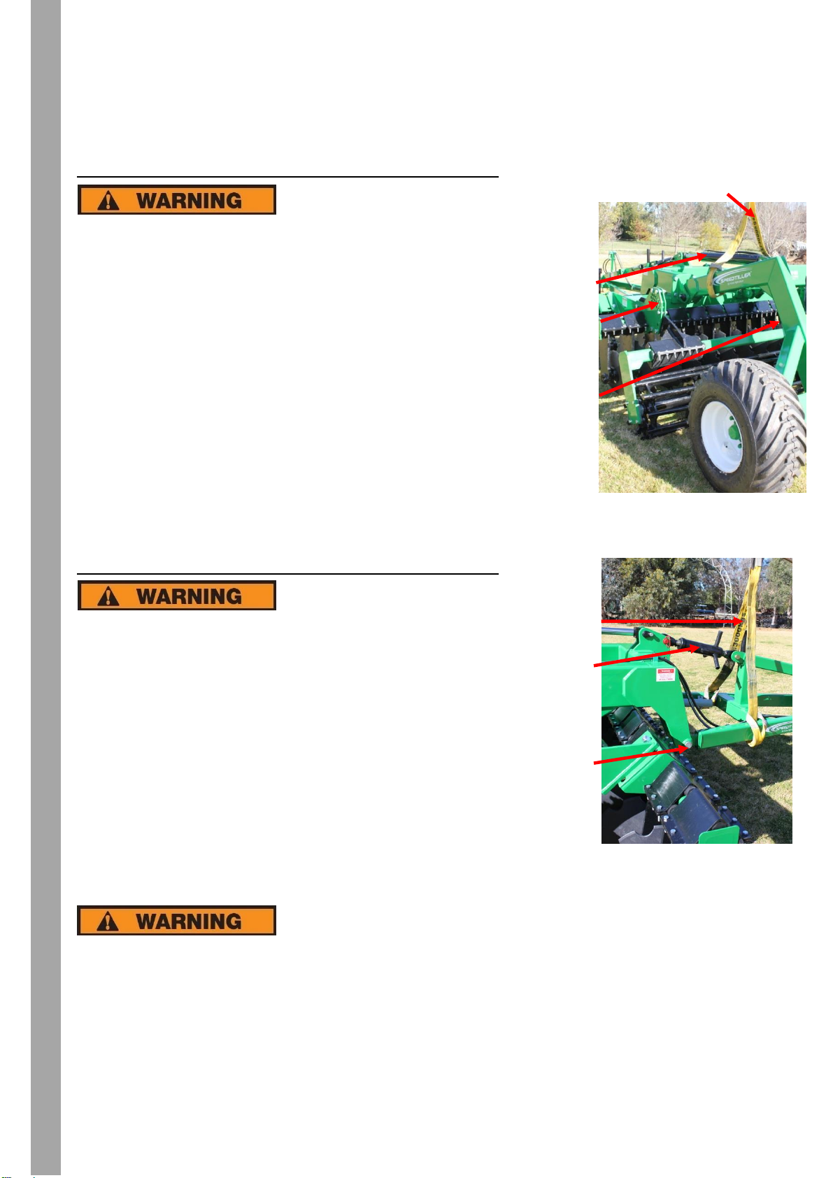
TO CONVERT FROM TRAILING MODE TO 3PL MODE
Main lift
ram
Attachment
pins
Rear
assembly
Tilt
Link
Sling
Attachment
Pins
Sling
Performing Maintenance
Figure 25
Figure 26
TO CONVERT FROM 3PL MODE TO TRAILING MODE
ARE BEING LIFTED INTO PLACE! SERIOUS INJURY MAY
OCCUR IF SAFETY PRECAUTIONS ARE NOT FOLLOWED.
K-LINE AGRICULTURE carries no responsibility for any personal injury, machine
damage, excessive wear, and failure of parts, related to improper use, adjustment or
lack of routine maintenance, as set out in this Operators Manual.
Any warranty given is at the sole discretion of K-LINE AGRICULTURE.
K-Line Ag ©
___________________________________________________________________
- Failure to observe instructions could result in serious
injury or death
1. Lower machine to ground.
2. Release oil pressure from system (using tractor hydraulics.)
i.e. rear wheels to rest only under their own weight on the
ground.
3. Ensure implement jack is installed correctly.
4. Remove tilt adjust link, see figure 8.
5. Remove lift ram & hoses. Store.
6. Attach sling to front drawbar as shown in figure 8.
7. Using suitable lifting equipment, remove pins as shown in
figure 8.
8. Remove drawbar. Store.
9. Attach sling to rear wheel assembly as shown in figure 9
10. Using suitable lifting equipment, remove pins as shown in
figure 9.
11. Store wheel assembly.
12. Check all bolts are tensioned correctly and pins are in place.
13. Machine is now converted and ready to be used as 3PL mode.
wheel
- Failure to observe instructions could result in serious
injury or death
1. Set machine on ground
2. Attach sling to front drawbar as shown in figure 26
3. Using suitable lifting equipment, set drawbar in place and
install attachment pins
4. Attach implement jack to front of drawbar
5. Attach tilt adjustment link. See figure 26
6. Attach sling to rear wheel assembly as shown in figure 25.
7. Using suitable lifting equipment, set rear wheel assembly in
place and insert attachment pins
8. Install lift ram as shown in figure 25
9. Attach hydraulic hoses to mounting cleats
10. Check all bolts are tensioned correctly and pins are in place.
11. Machine is now converted & ready to be used in trailing
mode.
KEEP WELL CLEAR OF
MACHINE PARTS AS THEY
Page | 22
Adjust

K-Line Ag ©
Performing Maintenance
___________________________________________________________________
Performing Maintenance
Good maintenance is your responsibility. Poor maintenance is an invitation to trouble.
- Make sure maintenance area has plenty of ventilation. Beware exhaust fumes may
cause asphyxiation.
Prior to commencing work, IDENTIFY ALL HAZARDS! Use control measures to
eliminate these dangers.
Use blocks to support frame of machine on level area free of obstruction.
Always use a safety support and chock the wheels.
Never use an implement jack to support the machine.
Never work under raised machine unless all components are securely positioned and
locked.
Engage all safety transport locks, chock wheels and front drawbar for temporary
service if machine is in free standing mode.
A fire extinguisher and first aid kit should be kept readily accessible while performing
maintenance on this equipment.
Follow the torque chart in this manual when tightening bolts and nuts.
Refer to bolt torque chart for head identification marking.
Always replace bolts with specified grades.
Where replacement parts are necessary for periodic maintenance and servicing,
genuine factory replacement parts must be used to restore your equipment to original
specifications.
If equipment has been altered in any way from original design, the manufacturer does
not accept any liability for warranty or personal injury.
Replace all shields and guards after servicing before moving.
After servicing, be sure all tools, parts and service equipment are removed.
The machine is identified by the serial number on the metal plate on the machine.
When requesting spare parts or maintenance service, please indicate the model and
number of your equipment to ensure prompt and efficient attention.
K-Line Agriculture spare parts and accessories have been specifically designed and
developed for the machines produced. We would call your attention to the fact that
non-genuine parts and accessories are not recommended by K-Line. Use of nongenuine parts and accessories releases K-Line from all liability and makes the
warranty void. The installation and/or use of non-genuine parts may, because of
technical characteristics of construction, may modify or influence the performance of
the machine negatively.
Hydraulic fluid escaping under pressure can have sufficient force to cause
injury. Keep all hoses and connections in good serviceable condition.
Failure to heed may result in serious personal injury or death. Escaping
hydraulic fluid under pressure can penetrate the skin causing serious
injury. Avoid the hazard by relieving the pressure before disconnecting
lines or performing work on the system. Make sure hydraulic fluid
Page | 23

K-Line Ag ©
Figure 28
Figure 27
- Always cage tires before seating
Failure to comply could result in serious injury or
Tire pressure
35PSI / 250KPA
Wheel nut tension
500lbs / 677nm
Performing Maintenance
___________________________________________________________________
connections are tight and all hydraulic hoses and lines are in good
condition before applying pressure to the system. Use a piece of paper or
cardboard, NOT BODY PARTS, to check for suspected leaks. Wear
protective gloves and safety glasses or goggles when working with
hydraulic systems. DO NOT DELAY! If an accident occurs, see a doctor
familiar with this type of injury immediately. Any fluid injected into the skin
or eyes must be treated within a few hours or gangrene may result.
Priming Hydraulic System
Fully extend and retract hydraulic cylinders
Repeat 3-4 times and hold lever extended each way for 10 to
15 seconds to release air from the system.
Lubrication of Rear Roller Bearings
Standard Rear Roller Bearings:
One point is provided for each bearing. Two pumps
of grease every 20 hours of operation.
Tire Safety & Pressures
Always cage tires before seating beads. (see
figure 27 & 28)
Never exceed a stated pressures when seating
beads.
Do not attempt to mount a tire unless you have
the suitable equipment and experienced
personnel.
Inflating tires can be dangerous. Always stand to
the side when inflating. (27 & 28)
Load ratings of replacement tires should meet or
exceed weight requirements.
Correct pressure is 35PSI / 250KPA
Before mounting wheel to machine, check all hub
and rim contact surfaces are undamaged and
free of paint, dirt and grease.
Lubricate wheel stubs with standard viscosity oil.
Tension wheel nuts to 500ft lbs / 677nm.
For field operation: Re-tension after first, fifth,
then every fifty hours of operation.
For road travel re-tension first 3miles (5kms),
10miles (15kms), and thereafter at 25miles
(40kms) intervals
beads.
- Never exceed stated pressures when
seating beads
Page | 24

K-Line Ag ©
Item
QTY.
Part
Current Part No.
Weight
(kg)
1
1
Complete Jump Arm Back (shown)
29000JAAR1
44.95
1 1 Complete Jump Arm Front
29000JAAF1
44.95
2
Jump Arm only Back
29000JAWR1
36.75
2
Jump Arm only Front
29000JAWF1
36.75
3
1
2900 Torsion Rubber (Requires Set of
4)
29000JAX23
0.58
4 1 2900 Jump arm Top Hat
29000THP08
4.78
5
6
2900 Jump Arm Bolt Kit - 6 x M12 Set
screw with conelok nut
29000JABK
0.54
5
1
2900 Jump Arm Bolt Kit - 1 x M12 Set
screw with conelok nut
29000JABK
0.09
6
4
2900 Disc Bolt Kit - 4 x Plough bolt with
nut and spring washer
29000PLBK
0.24
6
1
2900 Disc Bolt Kit - 1 x Plough bolt with
nut and spring washer
29000PLBK
0.06
7 1 18" x 5mm Scalloped Disc
9SD1805S
9.8
7 1 20" x 5mm Scalloped Disc
9SD2005S
10
7 1 22" x 5mm Scalloped Disc
9SD2205S
10.21
7 1 22" x 6mm Scalloped Disc
9SD2206S
10.9
7 1 24" x 6mm Scalloped Disc
9SD2406S
12.5
Performing Maintenance
Figure 29
Diagram F81
___________________________________________________________________
Attaching Jump Arm to Machine
Lift jump arm into position
Loosely attach top clamp plate with rear clamp plate bolt &
conelock nuts. (Just start by a few threads only & leave arm hanging loosely)
Slide in torsion rubbers
Loosely attach front clamp bolts & conelock nuts
Check positioning
Tension all clamp bolts with conelock
nuts provided.
Back Jump Arm - front view
Page | 25
K-Line Ag ©
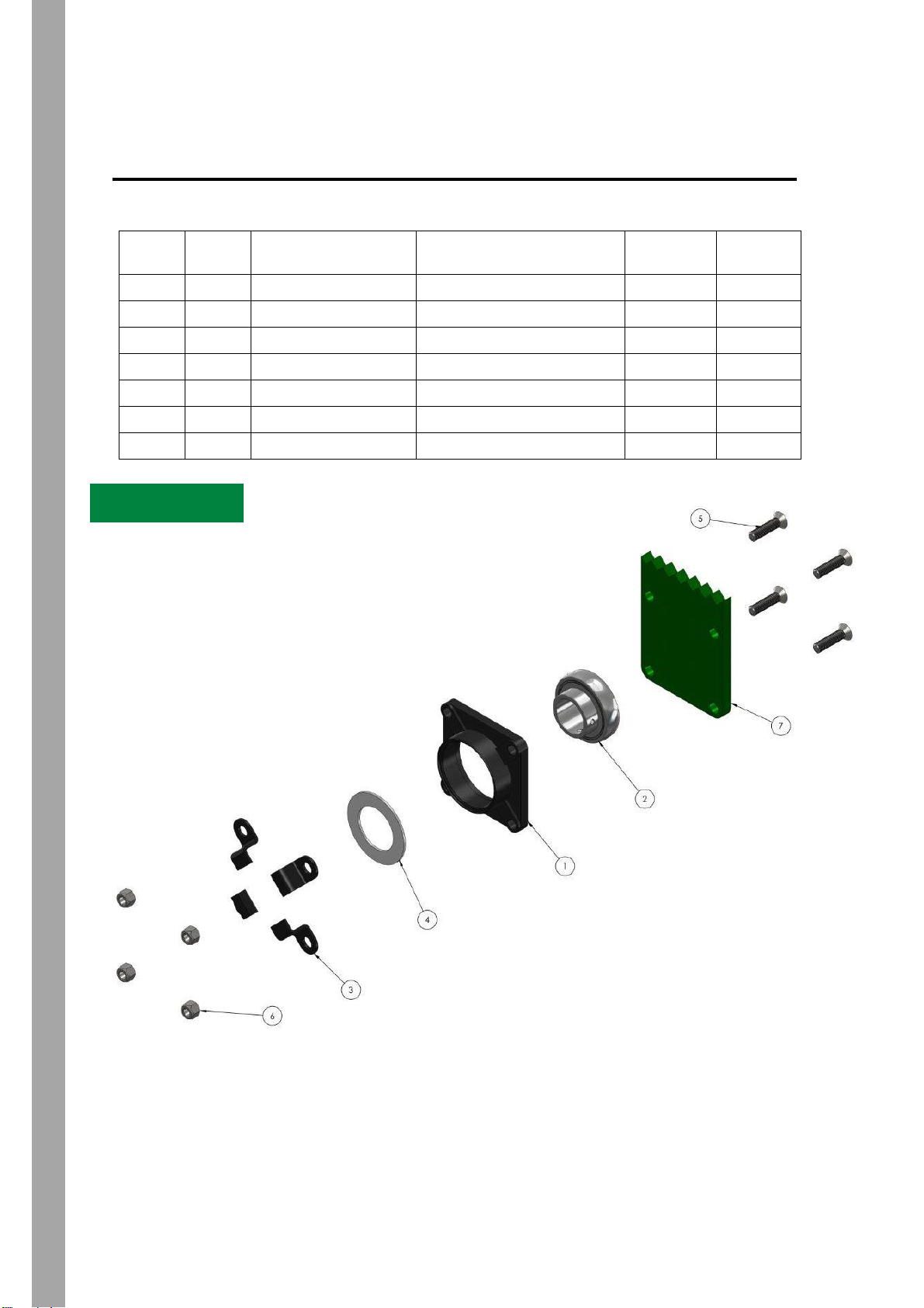
ITEM
NO.
QTY.
PART NUMBER
DESCRIPTION
WEIGHT
RRP
1 1 9BHF212
F212 Bearing housing
2.33
$ 144.00
2 1 9UC2123LS
UC212 Bearing
2.2
$ 110.00
3 4 9RBCO1
Bearing clip
0.13
$ 7.60
4 1 9PWMO4
Poly washer
0.03
$ 16.00
5 4 9M16065Z8CS
M16 x 65mm Socket Screw
0.1
$ 3.42
6 4 9M16CLZ
M16 Prevailing Torque Nut
5.605
$ 0.65
7
1
NA
NA
Rear Roller Bearing and dust protector- (Standard equipment)
Diagram F84
Figure 30
___________________________________________________________________
Page | 26

K-Line Ag ©
Item
QTY.
DESCRIPTION
PART NUMBER
RRP
1 1 2900 Jump arm bearing housing
29000JAM02
2 1 M85 Bearing housing cap
29000JAM05
$15.00
3 1 2900 Bearing Spacer
29000JAM03
$7.90
4 1 M40 Locking Washer
9MB08
$12.50
5 1 M40 Locking Nut
9KM08
$14.80
6 1 2900 Jump arm Seal
9SS508011ML
$15.00
7
1
6208 Bearing
9B62082RS
$10.00
8 1 DAC 4080 Bearing
9DAC4080
$20.00
9
1
MRV2090 Seal
MRV2090
$9.00
10 1 2900 Disk stub
29000JAW02
$65.00
Diagram F82
*NB- Spindle
torque tension
360ft lb / 500nm
Exploded View of Disc Arm Bearing
Performing Maintenance
Figure 31
___________________________________________________________________
Page | 27

K-Line Ag ©
ITEM
NO.
QTY.
PART NUMBER
DESCRIPTION
WEIGHT
RRP
1 1 2900LSSWM1
2900 Spray Stopper Mount
7.97
$185.00
2 1 2900LSSWA1
2900 Spray Stopper Angle
6.09
$105.00
3 1 2900LSSWS1
2900 Spray Stopper Shaft
1.78
$ 26.00
4 1 29000SSWM1
2900 Spray Stopper Hub
0.97
$ 78.00
5 1 29000JAX215
2900 Short Rubber
1.2
$ 16.00
6 1 29000SSWT1
2900 Spray Stopper Top Hat
3.32
$ 36.00
7
1
9CD2405HT
24" Coulter
7.61
$ 82.00
8 1 9SW62-40-1.6
ISC gal seal protector
0.02
$ 7.00
9 1 9MW50M4011
ISC Seal spacer
0.06
$ 4.20
10 1 9SW67.8-52-1.5
IDC bearing spacer
0.02
$ 7.50
11 1 29000SSPO1
Coulter hub cover
0.21
$ 14.00
12 1 9DRT396837
Bearing
0.18
$ 28.00
13-15 1 29000SSBKD
2900 Spray Stopper disc
bolt Kit
0.33185
$ 6.00
16-24 1 29000SSBK1
2900 Spray Stopper Mount
bolt kit
55.66998
$ 13.83
25 1 29000BWP01
Bearing washer
0.13
$ 5.10
26 1 9M16040Z8SS
M16 x 40mm Set screw
0.25414
$ 2.10
27
1
9TC50-65-8_50x65x8 oil seal
Oil Seal
0.12
$ 3.13
Performing Maintenance
Exploded View of Side Coulter
Diagram F83
Figure 32
___________________________________________________________________
Page | 28

K-Line Ag ©
Figure 41
Figure 33
Performing Maintenance
___________________________________________________________________
Page | 29
K-Line Ag ©
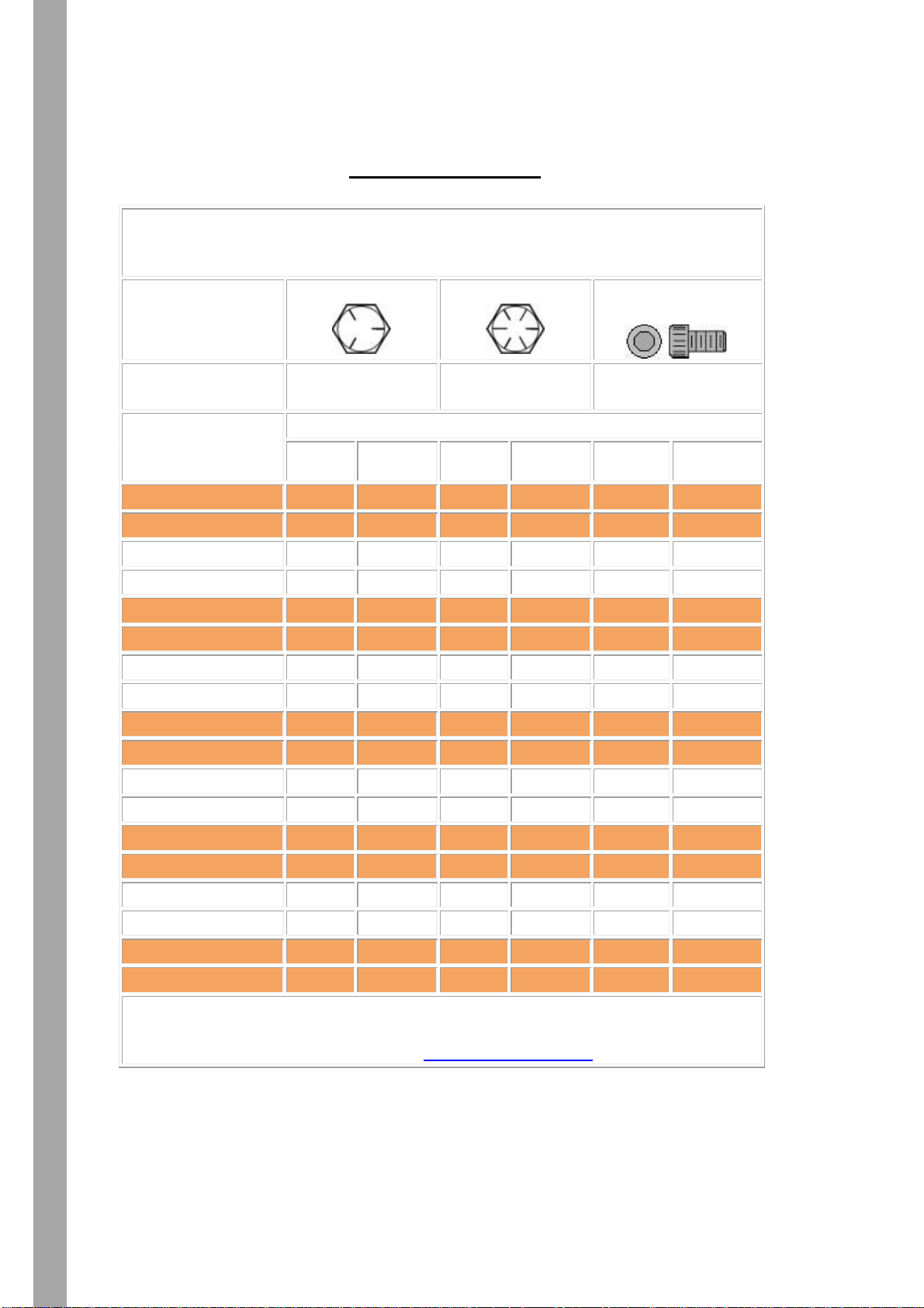
Bolt Torque Table
Estimated with clamp load as 75% of proof load
as specified in SAE J429 and ASME 574
Steel Grade
SAE 5
SAE 8
Socket Head
Cap Screws
Minimum Tensile
Strength PSI
120,000
150,000
1/4-1/2" 180,000
5/8-1" 170,000
Nominal Dia.
and
Thread Pitch
Bolt Torque Specs in Foot Pounds or (Inch Pounds)
Dry
Lubed
Dry
Lubed
Dry
Lubed
1/4-20
(101)
(76)
(143)
(107)
(168)
(120)
1/4-28
(116)
(87)
(147)
(123)
(192)
(144)
5/16-18
(209)
(157)
(295)
(221)
(348)
(264)
5/16-24
(231)
(174)
(327)
(245)
(384)
(288)
3/8-16
(372)
(276)
44
33
51
38
3/8-24
(420)
(312)
49
37
58
43
7/16-14
49
37
70
52
81
61
7/16-20
55
41
78
58
91
68
1/2-13
75
57
106
80
124
93
1/2-20
85
64
120
90
140
105
5/8-11
150
113
212
159
238
179
5/8-18
170
127
240
180
270
202
3/4-10
267
200
376
282
423
317
3/4-16
297
223
420
315
472
354
7/8-9
429
322
606
455
682
511
7/8-14
474
355
669
502
752
564
1-8
644
483
909
681
1022
767
1-12
722
542
1020
765
1147
860
Lubed means cleaned dry bolts lubricated with a standard medium viscosity
machine oil. Lubricate all contact areas of the bolts and washers. Lubricating
the bolts is the suggested method. Thread Engagement
Figure 34
Bolt Torque table
Performing Maintenance
___________________________________________________________________
Page | 30
K-Line Ag ©
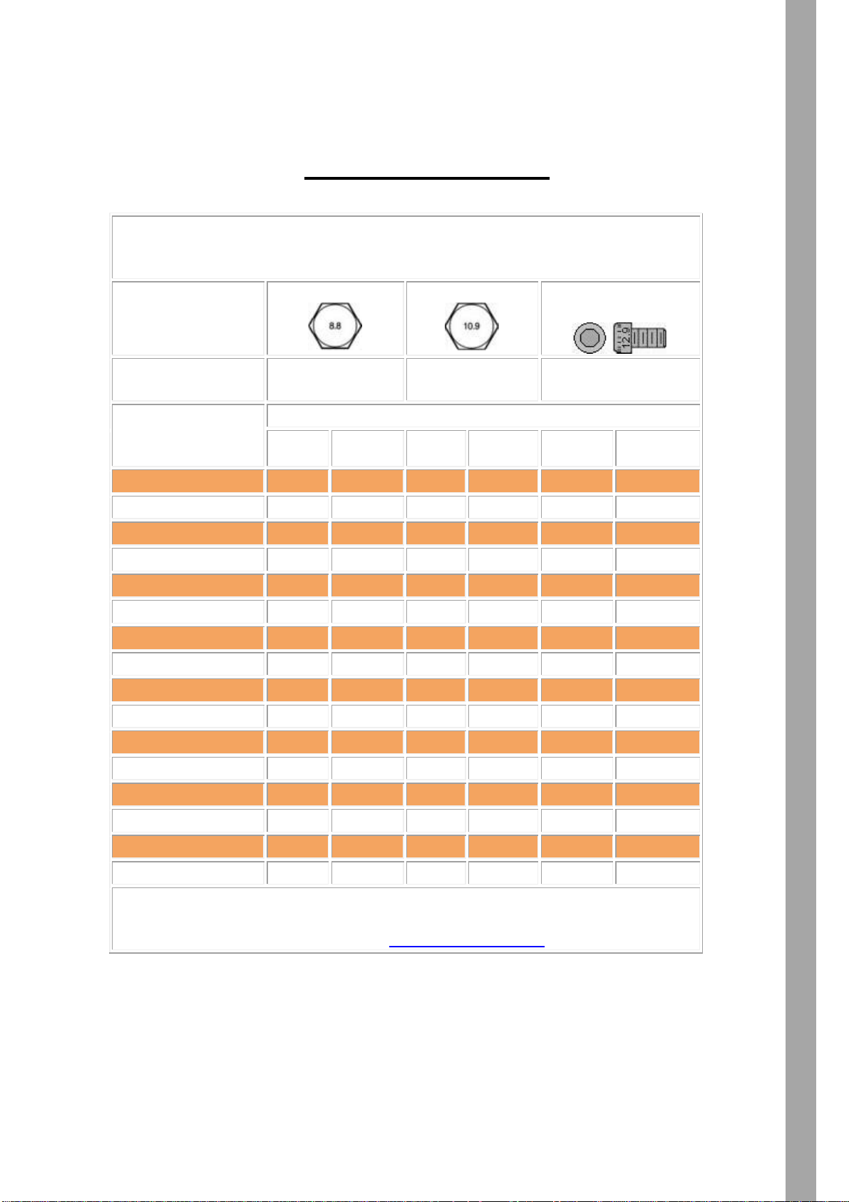
Metric Bolt Torque Table
Estimated with clamp load as 75% of proof load
as specified in ISO 898-1
Property
Class
8.8
10.9
12.9 Socket Head
Cap Screw
Minimum Tensile
Strength MPa
M6 - M16: 800
M20 - M30: 830
1040
1220
Nominal Size
and
Thread Pitch
Bolt Torque Specs in Foot Pounds or (Inch Pounds)
Dry
Lubed
Dry
Lubed
Dry
Lubed
M5 x 0.80
(54)
(41)
(78)
(59)
(91)
(68)
M6 x 1.00
(92)
(69)
(133)
(99)
(156)
(116)
M7 x 1.00
(156)
(116)
(222)
(167)
(260)
(195)
M8 x 1.25
(225)
(169)
(333)
(242)
(377)
(284)
M10 x 1.50
37
28
53
40
62
47
M12 x 1.75
65
49
93
69
108
81
M14 x 2.00
104
78
148
111
173
130
M16 x 2.00
161
121
230
172
269
202
M18 x 2.50
222
167
318
238
372
279
M20 x 2.50
314
235
449
337
525
394
M22 x 2.50
428
321
613
460
716
537
M24 x 3.00
543
407
776
582
908
681
M27 x 3.00
796
597
1139
854
1331
998
M30 x 3.50
1079
809
1543
1158
1804
1353
M33 x 3.50
1468
1101
2101
1576
2455
1842
M36 x 4.00
1886
1415
2699
2024
3154
2366
Lubed means cleaned dry bolts lubricated with a standard medium viscosity
machine oil. Lubricate all contact areas of the bolts and washers. Lubricating
the bolts is the suggested method. Thread Engagement
Figure 35
Metric Bolt Torque table
Performing Maintenance
__________________________________________________________________
Page | 31

K-Line Ag ©
2918U
2925U
2930U
Operating Width
(approx.)
5.7ft (1.75m)
8.2ft (2.5m)
9.8ft (3.0m)
Total overall
width
6.6ft (2.05m)
9.1ft (2.8m)
10.7ft (3.3m)
Number of discs
14
20
24
Disc cut spacing
5 inches
(125mm)
5 inches
(125mm)
5 inches
(125mm)
Adjustable disc
positioning
Variable to suit
conditions
Variable to suit
conditions
Variable to suit
conditions
Standard disc
size
22” x 6 gauge
(560 x 5mm)
22” x 6 gauge
(560 x 5mm)
22” x 6 gauge
(560 x 5mm)
Disc options
22” x ¼ (560 x
6mm)
24” x ¼ (610 x
6mm)
22” x ¼ (560 x
6mm)
24” x ¼ (610 x
6mm)
22” x ¼ (560 x
6mm)
24” x ¼ (610 x
6mm)
Speedtiller
approximate
weight
depending on
rollers etc.
4190lbs
(1900kg),
6505lbs
(2950kg),
7056lbs
(3200kgs)
Tractor Power
range
Transport Width
6.7ft (2.1m)
9.2ft (2.8m)
10.8ft (3.3m)
Tractor Hydraulic
remote
requirements
1 hydraulic
wheel lift
1 hydraulic
wheel lift
1 hydraulic
wheel lift
Hydraulic
Pressure
2800 PSI /
19000 KPA
Performing Maintenance
__________________________________________________________________
Specifications
Page | 32

K-Line Ag ©
2935U
2940U
Operating Width
(approx.)
11.5ft (3.5m)
13.1ft (4.0m)
Total overall
width
12.4ft (3.8m)
14ft (4.6m)
Number of discs
28
32
Disc cut spacing
5 inches
(125mm)
5 inches
(125mm)
Adjustable disc
positioning
Variable to suit
conditions
Variable to suit
conditions
Standard disc size
22” x 6 gauge
(560 x 5mm)
22” x 6 gauge
(560 x 5mm)
Disc options
22” x ¼ (560 x
6mm)
24” x ¼ (610 x
6mm)
22” x ¼ (560 x
6mm)
24” x ¼ (610 x
6mm)
Speedtiller
approximate
weight depending
on rollers etc.
7497lbs
(3400kgs)
7938lbs
(3600kgs)
Tractor Power
range
Transport Width
8.2ft (2.5m)
8.2ft (2.5m)
Transport Height
12.5ft (3.8m)
14.1ft (4.3m)
Tractor Hydraulic
remote
requirements
1 hydraulic
wheel lift
1 hydraulic
wheel lift
Hydraulic
pressure
2800 PSI /
19000 KPA
2800 PSI /
19000 KPA
Performing Maintenance
__________________________________________________________________
Specifications
Page | 33

K-Line Ag ©
Risk Management
__________________________________________________________________
RISK MANAGEMENT
Risk management is the process of finding out what may cause an injury, deciding what
may happen as a result, and doing something about it.
The steps of risk management are:
Identify the hazards to workplace health and safety arising from work activities
Assess the risks
Determine and implement control measures to reduce risk
Monitor and review the effectiveness of the control measures
IDENTIFYING HAZARDS
Prior to commencing work, all hazards related to the work tasks should be identified.
The selection of the appropriate work procedure(s) will depend on the type of work
procedure(s) and hazards involved. Regular safety inspections will also identify hazards
and ensure that control measures are in place.
RISK ASSESSMENT
Risk assessment allows appropriate control measures to be developed. Once hazards
have been identified, they should be assessed in terms of their potential to do harm. To
assess risk, consideration should be given to probability and consequences. SEE RISK
ASSESSMENT MODEL.
RISK CONTROL
Risk control is the process of eliminating or reducing risk factors. Control measures
should be chosen and implemented to eliminate or reduce risk as far as practicable.
When deciding on the most appropriate measures to use, practicality and acceptance of
the control measures should be considered. Safe Working Procedures will be developed
for all high – medium risk hazards.
MONITOR AND REVIEW CONTROL MEASURES
The risk identification, assessment and control process requires regular monitoring to
ensure the implemented control measures perform as originally intended and continue
to prevent or adequately control the risk of injury or incident. Control measures should
also be checked carefully to ensure that new hazards are not created, directly or
indirectly, by the original control measures.
Page | 34

K-Line Ag ©
Risk Management
AT ALL TIMES COMPLY WITH RECOMMENDATIONS
__________________________________________________________________
RISK ASSESSMENT MODEL
AND REQUIREMENTS OF THE MANUFACTURER AND
THE ENVIRONMENTAL PROTECTION AUTHORITY
Page | 35

K-Line Ag ©
CODE
HAZARDS
RISK
SCORE
CONTROL
REVISED
RISK SCORE
1(A).
Crushing – when adjusting
and cleaning, as machine
may drop without warning
1
Adjusting & cleaning must only be done when machine is
lowered or in transport position and only after all chains and
bolts have been checked for tightness & wear in the lower
position.
5
1(B).
Crushing - improper use of
jack
1
Ensure jack is installed correctly & jack receives regular
maintenance. Keep feet and body clear when operating.
5
1(C).
Crushing - when hitching
tractor
2
Ensure no personnel are between tractor & harrow bar when
hitching to tractor.
5
1(D).
Crushing - prior to priming
hydraulic system, as
machine may drop without
warning
1
Machine must be lowered into working position using suitable
lifting equipment before priming is effected by slightly
loosening fitting/s into cylinders and operating tractor
hydraulics to achieve full uninterrupted travel of cylinder
several times. Then retighten hydraulic tine fittings.
5
1(E).
Sudden lift of drawbar
causing severe injury, if
machine becomes
unhitched
1
Ensure all three jacks are correctly positioned and taking
weight before removing drawbar pin. Stickers warn operator.
5
2(A).
Penetration of oil - broken
or badly maintained
hydraulic lines
2
Maintain regular checks on hydraulic system for wear &
check all fittings are secure.
5
2(B).
Rupture of oil lines by over
pressure when machine
comes to sudden stop
before fully lowered to
working position
2
Ensure tractor oil flow is limited to reduce falling speed or do
not interrupt machine falling until machine is fully in lowered
position
5
3.
Collision – hydraulics
accidentally lowered when
machine is being operated
in transport
1
Safety pins must be put in place as soon as machine is put in
transport position and if travelling on public roads to
disconnect hydraulics from tractor.
5
Risk Management
__________________________________________________________________
K-LINE AGRICULTURE RISK ASSESSMENT
ALL HAZARDS & RISKS ARE CONTROLLED THROUGH SAFE WORKING
Page | 36
PROCEDURES & ADEQUATE SIGNAGE

K-Line Ag ©
__________________________________________________________________
WARRANTY
K-LINE AGRICULTURE has been known over the last 22 years for supplying an
ever expanding range of quality agricultural machinery.
K-LINE AGRICULTURE warrants the products it manufactures and distributes to be
free of defective materials and workmanship for a period of twelve months from date
of purchase, to the first owner.
Any part of the goods manufactured and distributed by K-LINE AGRICULTURE that
proves to be defective material, will be replaced or repaired by K-LINE
AGRICULTURE when returned to K-LINE AGRICULTURE at cost to purchaser and
at purchaser’s risk.
Goods sold shall only have the benefit of this warranty if the purchaser has complied
with the manufacturer’s instructions in relation to the maintenance and operation of
the said goods. All conditions and warranties implied by Law or Statute are hereby
expressly excluded and negative so far as legally permissible.
K-LINE AGRICULTURE is not otherwise liable for any direct, indirect or
consequential loss or damage howsoever arising or occurring, whether founded in
tort, contract, and statute or otherwise.
This warranty must be read as subject to the General Terms and Conditions and
does not cover misuse, neglect or negligence.
ANY CLAIM FOR WARRANTY IS ALSO SUBJECT TO THE FOLLOWING
CONDITIONS:
Machine has not been subject to misuse.
The speed limit of 20mph (32kmh) has been observed at all times.
The machine has not been used for custom or hire work.
Equipment must be handled, assembled, operated, maintained and stored
correctly in accordance with the manufacturer’s instructions by competent
personnel.
Warranty registration form must be signed by reseller and purchaser and
returned to K-LINE AGRICULTURE within 14 days of invoice. Warranty is not
valid unless registered.
Normal wear and tear, routine maintenance costs and accidental damage are
NOT covered by this warranty.
Any alteration of equipment or negligence in maintenance including the use of
non-genuine parts, renders this warranty null and void.
K-LINE AGRICULTURE will not authorize or reimburse expenses without a
warranty request form filled out to K-LINE AGRICULTURE satisfaction.
Signed on behalf of K-LINE AGRICULTURE
Page | 37

K-Line Ag ©
_______________________________________________________________________
THIS PAGE IS LEFT
INTENTIONALLY BLANK
Page | 38

Reseller:
Client First Name:
Client Last Name:
Salesman:
Trading Name:
Address:
Address:
Phone:
Phone:
Date of
Invoice:
Email Address:
Invoice No:
Start- Up Date:
Machine
Make &
Type:
Serial No:
Signed:
Signed:
WARRANTY REGISTRATION FORM
Conduct comprehensive risk assessment of machine with consideration for use
and maintenance
Ensure machine is delivered as per purchase order including options
All pins and lynch pins are in place
Hydraulic system is primed and operating properly (if applicable).
Check gearboxes for oil (if applicable).
Check belts for tightness (if applicable).
Instruction manual is supplied and explained.
It is the responsibility of the purchaser to:
Maintain in as new condition all warning and safety signs and devices at all times.
Ensure all operators are familiar with this manual and all safety devices and features
of the machine.
Maintain the machine at all times in a condition that is safe to operate, and ensure it
complies with any relevant safety acts of parliament, government authorities and
regulations.
Take every reasonable precaution as is commonly expected in this industry and in
the operation of the machine.
Before mounting, check with manufacturer of machine or consult engineer to ensure
strength and balance of machine is adequate to accommodate the K-Line products
you have purchased.
You must conduct a risk assessment, taking all risks into consideration before
commissioning machine for use.
To confirm registration for warranty, please return this page (signed) to
F :( 02) 6342 6913 or E: sales@k-line.net.au

K-Line Ag ©
________________________________________________________________________
THIS PAGE IS LEFT
INTENTIONALLY BLANK
Page | 40
WARRANTY REQUEST FORM
RESELLER: _______________________ CLIENT:
______________________
ADDRESS: _______________________ _____________________________
PHONE: _________________________ _____________________________
MACHINE MAKE & TYPE: ____________________________________________
SERIAL NO: ______________________ CUSTOMER ORDER NO: _______
INVOICE NO: _____________________ DATE OF INVOICE: ___________
FULL DESCRIPTION: ________________________________________________
___________________________________________________________________
___________________________________________________________________
___________________________________________________________________
CAUSE:
____________________________________________________________
___________________________________________________________________
___________________________________________________________________
DATE OF FAILURE: _______________ HOURS WORKED:
_____________
DATE OF REPAIR: ________________ HECTARES WORKED: _________
I AGREE:
1. That in accordance with the warranty given by K-LINE AGRICULTURE, I have
taken every reasonable precaution as is commonly expected in this industry
in the operation of the machine.
2. This claim is not due to negligence, lack of maintenance, routine wear & tear
or accidental damage & no unauthorised alteration has been made to this
machine.
OPERATOR: SIGNATURE ________________________________ DATE:
_____________________________________________
OWNER: SIGNATURE _________________________________ DATE:
_____________________________________________
OFFICE USE ONLY:
ACCEPTED: YES/NO DENIED: YES/NO
DATE: ___________________________________ DATE:
_____________________________
GOODS REPAIRED/ REPLACED/ REFUNDED FOR REASON FOR DENIAL:
_______________
CREDIT? (CIRCLE) ___________________________________
REFUND OR REIMBURSEMENT REQUIRED? ___________________________________
CHQ NO/ ADJUSTMENT NOTE NO: ___________ CHANGE REQUIRED? (CIRCLE)
SHIPPING DETAILS: _______________________ DESIGN
APPROVED BY: ___________________________ WORK METHOD
ACTION TAKEN: ___________________________ SUPPLIED PRODUCT
_________________________________________ REFER TO SUPPLIER
CLIENT SATISFIED YES/NO RECALL REQUIRED
FILE CLOSED BY: _________________________ DATE: _____________________________

K-Line Ag ©
________________________________________________________________________
THIS PAGE IS LEFT
INTENTIONALLY BLANK
Page | 42

K-Line Ag ©
_______________________________________________________________________
NOTES
___________________________________________________________________
___________________________________________________________________
___________________________________________________________________
___________________________________________________________________
___________________________________________________________________
___________________________________________________________________
___________________________________________________________________
___________________________________________________________________
___________________________________________________________________
___________________________________________________________________
___________________________________________________________________
___________________________________________________________________
___________________________________________________________________
___________________________________________________________________
___________________________________________________________________
___________________________________________________________________
___________________________________________________________________
___________________________________________________________________
___________________________________________________________________
___________________________________________________________________
___________________________________________________________________
___________________________________________________________________
___________________________________________________________________
___________________________________________________________________
___________________________________________________________________
___________________________________________________________________
___________________________________________________________________
___________________________________________________________________
___________________________________________________________________
___________________________________________________________________
___________________________________________________________________
___________________________________________________________________
___________________________________________________________________
___________________________________________________________________
___________________________________________________________________
___________________________________________________________________
___________________________________________________________________
___________________________________________________________________
___________________________________________________________________
___________________________________________________________________
___________________________________________________________________
___________________________________________________________________
___________________________________________________________________
___________________________________________________________________
___________________________________________________________________
Page | 43

K-Line Ag ©
_______________________________________________________________________
NOTES
___________________________________________________________________
___________________________________________________________________
___________________________________________________________________
___________________________________________________________________
___________________________________________________________________
___________________________________________________________________
___________________________________________________________________
___________________________________________________________________
___________________________________________________________________
___________________________________________________________________
___________________________________________________________________
___________________________________________________________________
___________________________________________________________________
___________________________________________________________________
___________________________________________________________________
___________________________________________________________________
___________________________________________________________________
___________________________________________________________________
___________________________________________________________________
___________________________________________________________________
___________________________________________________________________
___________________________________________________________________
___________________________________________________________________
___________________________________________________________________
___________________________________________________________________
___________________________________________________________________
___________________________________________________________________
___________________________________________________________________
___________________________________________________________________
___________________________________________________________________
___________________________________________________________________
___________________________________________________________________
___________________________________________________________________
___________________________________________________________________
___________________________________________________________________
___________________________________________________________________
___________________________________________________________________
___________________________________________________________________
___________________________________________________________________
___________________________________________________________________
___________________________________________________________________
___________________________________________________________________
___________________________________________________________________
___________________________________________________________________
___________________________________________________________________
Page | 44

K-Line Ag ©
_______________________________________________________________________
NOTES
___________________________________________________________________
___________________________________________________________________
___________________________________________________________________
___________________________________________________________________
___________________________________________________________________
___________________________________________________________________
___________________________________________________________________
___________________________________________________________________
___________________________________________________________________
___________________________________________________________________
___________________________________________________________________
___________________________________________________________________
___________________________________________________________________
___________________________________________________________________
___________________________________________________________________
___________________________________________________________________
___________________________________________________________________
___________________________________________________________________
___________________________________________________________________
___________________________________________________________________
___________________________________________________________________
___________________________________________________________________
___________________________________________________________________
___________________________________________________________________
___________________________________________________________________
___________________________________________________________________
___________________________________________________________________
___________________________________________________________________
___________________________________________________________________
___________________________________________________________________
___________________________________________________________________
___________________________________________________________________
___________________________________________________________________
___________________________________________________________________
___________________________________________________________________
___________________________________________________________________
___________________________________________________________________
___________________________________________________________________
___________________________________________________________________
___________________________________________________________________
___________________________________________________________________
___________________________________________________________________
___________________________________________________________________
___________________________________________________________________
___________________________________________________________________
Page | 45

THIS PAGE IS LEFT
INTENTIONALLY BLANK

THIS PAGE IS LEFT
INTENTIONALLY BLANK

K-Line Ag ©
K-Line Agriculture
PO Box 567
700 Division Avenue S
Cavalier ND 58220
Email: sales@k-lineag.com
K-Line Agriculture
PO Box 340
72-80 Young Rd
Cowra NSW 2794
Email: sales@k-line.net.au
002
__________________________________________________________________
DESIGNERS AND
MANUFACTURERS OF
QUALITY
AGRICULTURAL
MACHINERY
Speedtiller, Speed Tiller, Speedbuster, TrackAttack, Seed Commander, Crop-
Registered trademarks of K-Line Agriculture, Include:
Commander, Crop Commander, Aus-Cut, Scimitar, Carers of the Land.
TOLL FREE PHONE NUMBER:
USA- 1800 556 6882
AUS- 1800 194 131
Page | 48
 Loading...