

Page 1

KL 20030 NAV
EGR LEAK DETECTION KIT
2010 MAXXFORCE DT, 9 & 10
OPERATING INSTRUCTIONS
Page 2

INTRODUCTION:
This manual contains information to help you to learn about the safe and proper use of the
KL20030 EGR Leak Detection Kit. The instructions included in this manual are not necessarily all-inclusive. K-Line® cannot anticipate all conceivable or unique situations. You must
make sure all conditions and procedures do not jeopardize your personal safety.
DISCLAIMER: All information, images, and speci cations contained in this manual are
based on the latest information available at the time of publication. K-Line® reserves the
right to make changes at any time without notifying any person or organization of such
revisions or changes. K-Line® is not liable for incidental or consequential damages (including lost pro ts) in connection with the furnishing, performance, or use of this material. If
necessary, obtain additional information from the vehicle manufacturer.
SAFETY PRECAUTIONS:
Before using the KL20030NAV EGR Leak Detection Kit read, understand,
and follow the safety precautions and operating instructions outlined in
this manual. This equipment must be operated by quali ed personnel. The
operator must be familiar with vehicle cooling systems, coolants, and the
dangers they present.
If the operator cannot read English, operating instructions and safety
precautions must be read and discussed in the operator’s native language.
Si el operador no puede leer inglés, las instrucciones de operación y las
precauciones de seguridad deberán leerse y comentarse en el idioma
nativo del operador.
Si l’utilisateur ne peut lire l’anglais, les instructions et les consignes de
sécurité doivent lui être expliquées dans sa langue maternelle.
Do not drink antifreeze or solution. Avoid inhaling mist or hot vapors.
(Ethylene glycol base.) If swallowed, drink two glasses of water; induce
vomiting; and call a physician. If inhaled, move to fresh air and call a physician.
Use the unit in locations with mechanical ventilation that provides at least four
air changes per hour. If accidental system discharge occurs, ventilate the work
area before resuming work.
Contact with antifreeze/coolant may cause injury. Hot antifreeze/coolant
can burn skin and injure eyes. Wear protective equipment, including safety
goggles and gloves, when operating this equipment. If contact with eyes occurs,
call a physician immediately, and ush eyes with cold water for 30 minutes. If
contact with skin occurs, thoroughly wash area with soap and water.
2
Page 3

OBJECTIVE:
NTENT
S
:
This tool kit is designed to detect leaks on the EGR cooler using two separate and di erent
tests. The rst test uses air pressure while the operator looks for air pressure decay on
an air pressure gage to check for leaks in the exhaust side of the EGR Cooler system. The
second test uses air pressure while the operator looks for leaks in the form of bubbles in
a can of water to check for leaks in the coolant side of the EGR Cooler system.
APPLICATION:
2010 MaxxForce DT, 9 & 10
CONTENTS:
KL20030-1
Leak Detection Plate
KL20030-3
Gooseneck End Seal
PART #DESCRIPTION QTY
KL20030-1 Leak Detection Plate 1
KL20030-2 Double Hole Seal 1
KL20030-3 Gooseneck End Seal 1
KL20030-4 Sealing Plug 2
KL20030-2
Double Hole Seal
KL20030-4
Sealing Plug
3
Page 4
GENERAL USE AND INSTRUCTIONS:
CAUTION: This tool kit uses compressed air at high pressures! Use extreme caution
during testing! For your safety, make sure all ttings are tight and do not
stand in front of ttings while under pressure!
SAFETY GLASSES MUST BE WORN WHEN USING SHOP AIR.
BEFORE PROCEEDING:
Clean all sealing surfaces on the EGR Cooler. This will insure proper sealing of all the tools,
and will eliminate any error in the procedure.
NOTE: To reduce the chance of damaging the EGR cooler, set the Pressure Regulator
(KL20020-13) to 55 psi before connecting it to the system and beginning the test.
NOTE: Always conduct the two EGR Cooler tests in the order shown. Completing the tests
in a backwards order could give faulty results.
INSTALL TOOLS - TEST #1
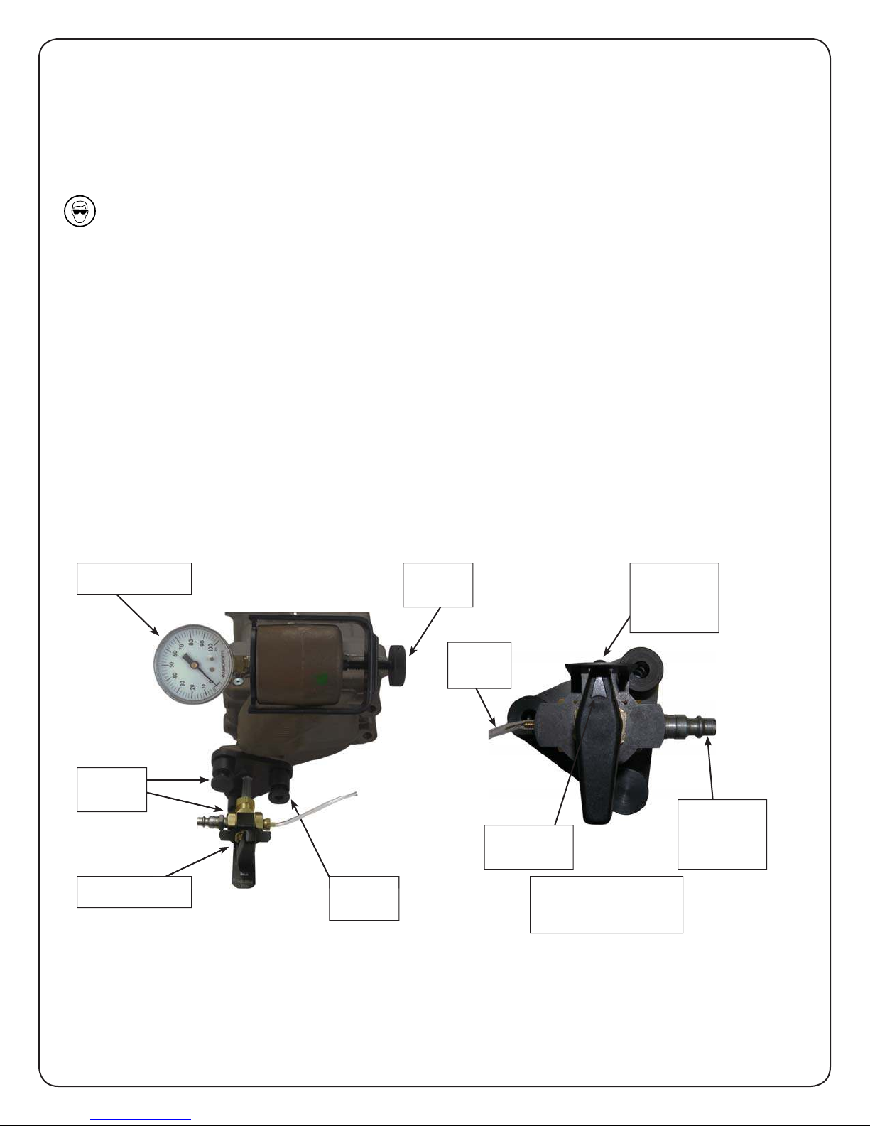
The EGR Cooler shown below with required tools installed to complete Test #1.
KL200303
Knurled
Knob
KL200301
Knurled
Knob
Knurled
Knob
Test 2
Hose
Indicating
Arrow
KL20030-1
Test 1
Position 2
Closed
Position 1
Air Inlet
BOTTOM VIEW
Test 1
KL20030-1:
1. Place the tool on the ange, aligning the knurled knobs with the proper locations. There
should be two studs and a threaded hole on the ange, and the tool has fasteners to
match this.
4
Page 5
2. Tighten all three knurled knobs hand tight approximately the same amount. This will
compress the imbedded o-ring on the bottom of the tool against the ange to seal this
port. Do not over tighten the knobs as damage to the o-ring could result.
KL20030-3:
1. Before installing the tool, back the knurled knob out several turns to insure that there
is enough clearance to properly install the tool over the end of the neck on the cooler.
2. Put the tool in place as shown in image on Page 4. The tool will center itself in the cavity
when properly seated.
3. Tighten the knurled knob hand tight to compress the o-ring. Do not over tighten the
knob as damage to the o-ring could result.
KL20020-13 (PRESSURE REGULATOR):
1. Connect a pressurized air line to the regulator assembly, and verify that the air pressure
is being properly regulated to 55 psi. If it is not, use the regulator’s adjustment knob to
adjust the pressure to 55 psi.
PRESSURIZE THE SYSTEM AND CONDUCT TEST #1
NOTE: The air poppet in KL20030-3 is set to 60 PSI to prevent damage to the coolers and for
safety in the case of over pressurization. The compressed air line that is connected
to this system must be regulated to 55 PSI.
1. Begin with the 3-way valve on the KL20030-1 at Test 1 - Position 2 (Closed). Connect the
KL20020-13 Pressure Regulator to the air inlet on the KL20030-1 at Test 1 - Position 1 (Air
Inlet) on the 3-way valve.
2. After the regulated air line is connected to the KL20030-1, turn the handle on the 3-way
valve to Test 1 - Position 1 (Air Inlet) to allow the system to pressurize. Verify that the
system has reached full pressure on the gage on the KL20030-3.
3. Turn the handle on the 3-way valve on the KL20030-1 back to Test 1 - Position 2 (Closed).
The operator must watch the system for a minimum of 10 minutes for decay in air
pressure. A reduction in pressure indicates a leak in the cooler, and a failed EGR Cooler.
NOTE: If there is a pressure decay indicating the EGR cooler has failed Test #1, then Test #2
is not required; if the EGR cooler passes Test #1, proceed with Test #2. Be sure to
record if the EGR cooler passed or failed the pressure decay test.
5
Page 6
INSTALL TOOLS - TEST #2
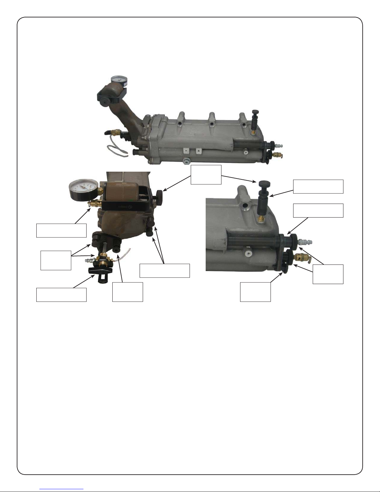
The EGR Cooler is shown below with all tools installed. Operator will need a container of
water to put the hose in to watch for bubbles. Tools KL20030-1 and KL20030-3 should be
installed on the cooler already from Test #1.
Knurled
Knob
KL200201
KL200302
KL200303
Knurled
Knob
Knurled
Knob
KL200301
Knurled
Knob
KL200304
Knurled
Screw
KL20020-1:
1. Before installing the tool, back the knurled knob out several turns to insure that there is
enough clearance to properly install the quick connect.
2. Install the tool onto the pipe as shown. Make sure the quick connect is fully seated and
locked onto the pipe before hand tightening the knurled knob.
3. When the quick connect is fully seated, the knurled knob can be hand tightened until
the rubber seal contacts the pipe. Do not over tighten the knob as damage to the o-ring
and the pipe could result.
KL20030-2:
1. Before installing the tool, back the knurled knobs out several turns to insure that there
is enough clearance to properly install the tool.
6
Page 7
2. Line the tool up with the proper holes in the cooler as shown. Hand tighten the
appropriate knurled screw for the cooler down into the threaded hole until the tool
contacts the surface.
3. Hand tighten the knurled knobs on the tool in order to compress the o-rings and seal
against the inside of the pipes. Do not over tighten the knobs as damage to the o-rings
could result.
KL20030-4:
1. Thread the plugs into the ports and hand tighten until the o-rings contact the sealing
surface. Do not over tighten the plugs as damage to the o-rings could result.
KL20020-13 (PRESSURE REGULATOR):
1. Connect a pressurized air line to the regulator assembly, and verify that the air pressure
is being properly regulated to 55 psi. If it is not, use the regulator’s adjustment knob to
adjust the pressure to 55 psi.
PRESSURIZE THE SYSTEM AND CONDUCT TEST #2
IMPORTANT: Begin by turning the 3-way valve on tool KL20030-1 to Test 2 (Hose). This is
necessary for this part of the test to be completed properly. Not completing this
would result in an invalid test and would provide false results.
NOTE: The air poppet in KL20030-2 is set to 60 PSI to prevent damage to the coolers
and for safety in the case of over pressurization. The compressed air line that is
connected to this system must be regulated to 55 PSI.
1. Connect the KL20020-13 Pressure Regulator to the KL20030-2. DO NOT INSTALL ONTO
THE KL20030-1.
2. Check for leaks by placing the end of the hose from the KL20030-1 into a container of
water to a depth of .375” which is marked with red dye on the hose. The system must
remain pressurized and the operator should look for air bubbles to come from the end
of the hose. The bubbles indicate a leak, and a very small leak may take up to 5 minutes
to appear. This is the maximum time that would be required of the operator to watch
for air bubbles to be sure there are no leaks in the cooler.
NOTE: Be sure to record if the EGR coolers passed or failed the leak test.
DISASSEMBLY
1. Disconnect the compressed air line from the system.
2. Remove all tools from coolers and clean any oil and dirt from them. Refer to installation
instructions and reverse them for removal.
3. Replace the tools in the storage case for protection.
7
Page 8
For product information or
to purchase replacement parts
CALL CUSTOMER SERVICE AT
1-800-824-K-LINE (5546)
Local (616) 396-3564
FAX 1-800-528-9138 or (616) 396-8974
www.klineind.com
Copyright 2011 K-Line® Industries, Inc.
P/N 4420030-200 Rev. 8/11
 Loading...