

Klimor MCKT–HPX 2, MCKT–HPX 1, MCKT–HPX 3 Operation And Maintenance Manual
KLIMOR
OPERATION AND MAINTENANCE MANUAL DTR HPX.08 v.8
PAGE
GDYNIA
COMPACT AHU MCKT-HPX
2014 1/14
KLIMOR S.A, 81-035 Gdynia, ul. B. Krzywoustego 5
Fax: (+48 58) 783-98-88; Tel.: (+48 58) 783-99-99
Service – Fax: (+48 58) 783-98-88; T el.: (+48 58) 783-99-50/51 Mobile: (+48) 510 098 081
Information in this document is subject to change
email: klimor@klimor.pl – Office
serwis@klimor.pl – Service
COMPACT VENTILATION UNIT
WITH HEAT PUMP
MCKT-HPX
SERVICE
Tel.: (+48 58) 783 99 50/51
Fax: (+48 58) 783 98 88
Mobile: (+48) 510 098 081
Email: serwis@klimor.pl
GDYNIA, December 2014

KLIMOR
OPERATION AND MAINTENANCE MANUAL DTR HPX.08 v.8
PAGE
GDYNIA
COMPACT AHU MCKT-HPX
2014 2/14
KLIMOR S.A, 81-035 Gdynia, ul. B. Krzywoustego 5
Fax: (+48 58) 783-98-88; Tel.: (+48 58) 783-99-99
Service – Fax: (+48 58) 783-98-88; T el.: (+48 58) 783-99-50/51 Mobile: (+48) 510 098 081
Information in this document is subject to change
email: klimor@klimor.pl – Office
serwis@klimor.pl – Service
TABLE OF CONTENT ........................................................................................................................... PAGE
1. GENERAL INFORMATION ................................................................................................................. 3
2. TECHNICAL SPECIFICATION AND APPLICATION .......................................................................... 3
3. AHU CONSTRUCTION ....................................................................................................................... 5
4. OPERATION PRINCIPLE ................................................................................................................... 5
4.1 THERMAL BALANCE ......................................................................................................................... 5
4.2 OPERATION OF CROSS-FLOW EXCHANGER................................................................................ 6
4.3 OPERATION OF THE HEAT PUMP ................................................................................................... 7
4.3.1 DESCRIPTION OF THE COOLING DEVICE ..................................................................................... 7
4.3.2 OPERATION OF COOLING DEVICE ................................................................................................. 7
4.3.3 OPERATION OF THE HEAT PUMP AT LOW EXTERNAL TEMPERATURES ................................. 8
5. CONTROL SYSTEM ........................................................................................................................... 8
5.1 DIAGRAM OF THE CONTROL SYSTEM ........................................................................................... 8
5.2 CONTROL OF STANDARD EQUIPMENT ......................................................................................... 9
5.2.1 TURNING ON THE AHU ..................................................................................................................... 9
5.2.2 DELAYED COOLING SYSTEM PROTECTION ................................................................................. 9
5.2.3 COOLING SYSTEM PROTECTION ................................................................................................... 9
5.2.4 AIR PARAMETER ADJUSTMENT ...................................................................................................... 9
5.2.5 FILTER PRESSURE GAUGES ........................................................................................................... 9
5.2.6 DEFROSTING THE CROSS-FLOW EXCHANGER ........................................................................... 9
5.2.7 FAN OPERATION ADJUSTMENT SIGNALS ..................................................................................... 9
5.3 CONTROL OF OPTIONAL EQUIPMENT ........................................................................................... 9
5.3.1 DAMPERS ........................................................................................................................................... 9
5.3.2 PRELIMINARY HEATER .................................................................................................................... 9
6. COMMISSIONING ............................................................................................................................ 10
7. SCOPE OF THE DELIVERY ............................................................................................................. 10
8. TRANSPORT AND STORAGE ......................................................................................................... 10
9. AHU ASSEMBLY............................................................................................................................... 10
9.1 SUSPENDING THE AHU .................................................................................................................. 10
9.2 DRAINING CONDENSATE ............................................................................................................... 11
9.3 ELECTRICAL CONNECTION ........................................................................................................... 11
10. FEATURED OPTIONAL EQUIPMENT ............................................................................................. 11
10.1 NGS – PRELIMINARY WATER HEATER ........................................................................................ 11
10.2 NGS – PRELIMINARY ELECTRICAL HEATER ............................................................................... 12
11. FIRST START-UP ............................................................................................................................. 12
12. OPERATION AND MAINTENANCE ................................................................................................. 13
13. FAULTY AHU OPERATION .............................................................................................................. 13
14. H&S PRECAUTIONS ........................................................................................................................ 13
15. SERVICE INFO ................................................................................................................................. 13
16. COMMISSIONING PROTOCOL ....................................................................................................... 14
KLIMOR
OPERATION AND MAINTENANCE MANUAL DTR HPX.08 v.8
PAGE
GDYNIA
COMPACT AHU MCKT-HPX
2014 3/14
KLIMOR S.A, 81-035 Gdynia, ul. B. Krzywoustego 5
Fax: (+48 58) 783-98-88; Tel.: (+48 58) 783-99-99
Service – Fax: (+48 58) 783-98-88; T el.: (+48 58) 783-99-50/51 Mobile: (+48) 510 098 081
Information in this document is subject to change
email: klimor@klimor.pl – Office
serwis@klimor.pl – Service
1. GENERAL INFORMATION
The purpose of this OMM manual is to made the installers and users aware of the construction as well as correct
operation and maintenance of the MCKT-HPX Air Handling Unit. Before the device installation as well as before
launching and operating the device you should carefully read this OMM and strictly follow all instructions herein.
Failing to observe the guidelines and recommendations
contained in the operation and maintenance
manual exempts the manufacturer
from any warranty-related obligations.
KLIMOR reserves the rights to implement design and material changes without prior notice, in relation to
modernization and improvement of the product.
2. TECHNICAL SPECIFICATION AND APPLICATION
Compact MCKT-HPX AHU is an air supply-exhaust unit designed for ventilation with heat recovery in any rooms
such as: shops, restaurants, offices, production halls, residential buildings, houses, etc. The AHU is located inside
the building. It is powered with electric energy. The heat pump enables to cool down the air in summer and heat it up
in winter. AHU's operating position – suspended.
The unit is not designed to operate in environments with air temperature exceeding 45°C and relative humidity over 60% as well as in environments endangered by explosion of flammable gases and vapors containing
organic solvents or other aggressive substances.
L
W
H
B
A
Okno inspekcyjn
e
Rozdzielnica RZ
S
M
C
K
T
-
H
P
X
Uchwyt zawiesia
1
1
2
2
3
3
4
4
W
+
2
0
0
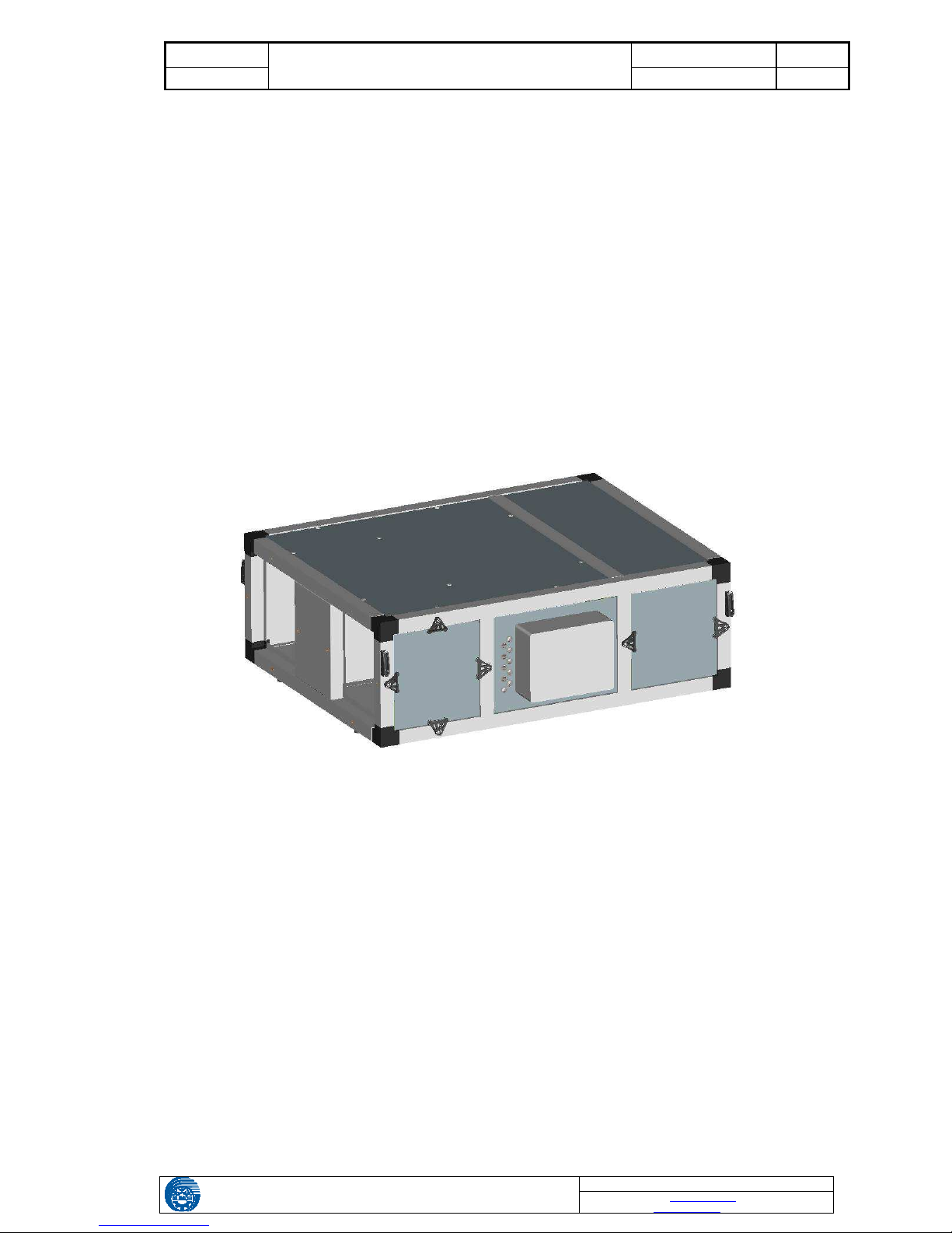
Picture no. 1 Compact MCKT-HPX AHU (main picture, top view)
STANDARD AIR FLOW
1– Inlet of external air
2– Outlet of supply air
3– Inlet of exhaust air
4– Discharge of extracted air
NON-STANDARD (i.e. LEFT-SIDE) AIR FLOW
3– Inlet of external air
4– Outlet of supply air
1– Inlet of exhaust air
2– Discharge of extracted air
KLIMOR
OPERATION AND MAINTENANCE MANUAL DTR HPX.08 v.8
PAGE
GDYNIA
COMPACT AHU MCKT-HPX
2014 4/14
KLIMOR S.A, 81-035 Gdynia, ul. B. Krzywoustego 5
Fax: (+48 58) 783-98-88; Tel.: (+48 58) 783-99-99
Service – Fax: (+48 58) 783-98-88; T el.: (+48 58) 783-99-50/51 Mobile: (+48) 510 098 081
Information in this document is subject to change
email: klimor@klimor.pl – Office
serwis@klimor.pl – Service
Table no. 1 Technical parameters, part 1
MCKT–HPX 1 MCKT–HPX 2 MCKT–HPX 3
Length L
[mm]
1342 1742 1892
Width W
[mm]
1042 1312 1468
Hight H
[mm]
452 552 602
Ventilation port A x B
[mm]
333 × 352 467 × 452 545 × 502
Connector size A x B
[mm]
390 × 350 465 × 450 560 × 500
Weight
kg
137 225 295
Air filters
Type
FS-100 250x350 G4 FS-100 450x450 G4 FS-100 550x500 G4
*For the unit equipped with the control system the “W” dimension is enlarged by 250mm.
Table no. 2 Technical parameters, part 2
MCKT–HPX 1 MCKT–HPX 2 MCKT–HPX 3
Range of airflow rate
m3/h
700 1000 1500 2100 2300 3200
Heating
1
kW
8.6 10.3 16.8 21.1 26.3 31.0
Cooling
2
kW
5.0 6.2 9.6 15.5 17.0 20.2
Fan power output
kW
2×0.5 2×0.5 2×1.1
Fan voltage
Ph/V/Hz
1×230V/50
1×230V/50
3×230/50
Fan current
A
2×2.2 2×2.2 2×2.23
Compressor power consumption (winter)
kW
1.5 1.6 3.0 3.2 4.3 4.9
Compressor power consumption (summer)
kW
1.8 1.9 3.3 3.4 4.7 5.6
Compressor voltage
Ph/V/Hz
1x230V/50
3×400/50 3×400/50
Max compressor current
3
A
14.0 10.4 15.8
Cooling medium
R407C R407C R407C
Amount of cooling medium
kg
2.0 3.0 4.5
Sound power level for suction/pressing duct
dB(A)
55/60 63/68 62/67 71/76 69/75 76/81
Level of acoustic pressure at 1m
from the casing for A=15m2
dB(A)
44 52 51 60 58 65
1- For parameters: external temperature -5°C; φ=80%, room temperature 20°C; φ=50%
2- For parameters: external temperature 32°C; φ=50%, room temperature 24°C; φ=50%
3- Max nominal compressor engine current.
Table no. 3 Dedicated optional equipment
MCKT–HPX 1 MCKT–HPX 2 MCKT–HPX 3
Size Max output Size Max output Size Max output
NGS water heater NGS-250 10kW NGS-400 23kW NGS-500 55kW
Electrical heater NGE NGE-1 4.5kW NGE-2 9kW NGE-3 13.5kW
Multi-surface damper
A.DPR 390×350 A.DPR 465×450 A.DPR 560x500
Flexible connection FC 390×350 FC 465×450 FC 560x500
Detailed data are listed in the chapter related to the optional equipment.
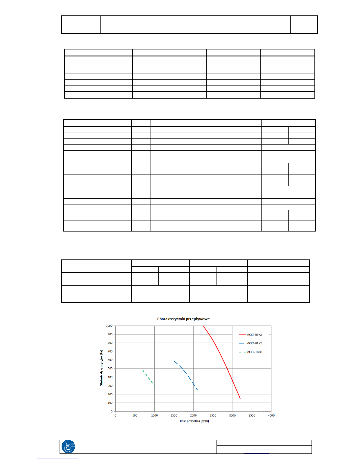
Chart no. 1 MCKT-HPX available pressure

KLIMOR
OPERATION AND MAINTENANCE MANUAL DTR HPX.08 v.8
PAGE
GDYNIA
COMPACT AHU MCKT-HPX
2014 5/14
KLIMOR S.A, 81-035 Gdynia, ul. B. Krzywoustego 5
Fax: (+48 58) 783-98-88; Tel.: (+48 58) 783-99-99
Service – Fax: (+48 58) 783-98-88; T el.: (+48 58) 783-99-50/51 Mobile: (+48) 510 098 081
Information in this document is subject to change
email: klimor@klimor.pl – Office
serwis@klimor.pl – Service
3. AHU CONSTRUCTION
- The MCKT-HPX AHU's casing is made of framework casing made of anodized aluminum profiles and plastic corners, and galvanized steel sheet and non-flammable mineral wool which provides appropriate thermal and acoustic
insulation. The casing panels are 50 mm thick.
Inspection panels are equipped with handles
and are mounted to the framework with oneand two-side clamps
The AHU's framework is equipped with handles enabling suspension of the unit to ceiling
with bars.
Picture no. 2 Inspection panels
AHU's side masking covers can be arranged in
different ways, enabling 16 combinations of ventilation port arrangements.
Picture no. 3 Side covers masking the ventilation ports
- MCKT-HPX AHU internal equipment: two G4-class cartridge filters, plate cross-flow heat exchanger, two axialradial fans with direct drive and complete sets of heat pump: air-air with cooling system and two CuAl exchangers.
The heat pump enables cooling of supply air in summer and heating it in winter.
In the lower part of the inspection plate there are connections (hose connectors) for draining condensate water from
the cross-flow heat exchanger and cooler outside the AHU.
- The MCKT-HPX AHU is equipped with complete system of power supply and control system. The RZS box is attached to the AHU side wall. The AHU is directly controlled by the control panel. Information regarding operating the
unit are attached.
4. OPERATION PRINCIPLE
The MCKT-HPX AHU can operate only with the cross-flow exchanger or with the cross-flow exchanger and heat
pump.
The most beneficial external air temperate enabling the highest heat pump efficiency for cooling is above -5°C. In
case of lower temperatures the control system switches off the cooling system and the unit operates in heat recovery
mode only with the cross-flow exchanger. To ensure proper operation of the heat pump, in order to heat up air to
required temperature, it is necessary to use preliminary NGS water heaters or NGE electrical heaters which heat up
external air up to -5°C.
4.1 THERMAL BALANCE
Compact MCKT-HPX AHU equipped with the cross-flow heat exchanger and heat pump forms a high-performance
heat recovery system for a ventilated room. However ventilated rooms have to be source of heat in order to enable
heat recovery. That is why at the stage of designing heating and ventilation system it is necessary to carry out the
room's thermal balance – a balance of profit and loss. Ventilated rooms should be equipped with independent heating provided by radiators, floor heating or other heating method, while the MCKT-HPX AHU should only take care of
heating up the supply air.
 Loading...