

Klimor MCKS, MCKP, MCKH Operation And Maintenance Manual
OPERATION AND MAINTENANCE MANUAL DTR MCK v.2.4
PAGE
GDYNIA
MODULAR AIR HANDLING UNITS
MCKS, MCKH, MCKP
2017 EN 1/45
KLIMOR Spółka z ograniczoną odpowiedzialnością Sp.k., 81-035 Gdynia, ul. B. Krzywoustego 5
Fax: (+48 58) 783-98-88; Tel.: (+48 58) 783-99-99
Service - Fax: (+48 58) 783-98-88; Tel.: (+48 58) 783-99-50/51 Mobile: (+48) 510 098 081
Information in this document is subject to change
email: klimor@klimor.pl - office
serwis@klimor.pl - service
MODULAR AIR HANDLING UNITS
MCKS; MCKH; MCKP
ISO 9001
SERVICE
Tel.: (+48 58) 783 99 50/51
Fax: (+48 58) 783 98 88
Mobile: (+48) 510 098 081
Email: serwis@klimor.pl
GDYNIA July 2017

OPERATION AND MAINTENANCE MANUAL DTR MCK v.2.4
PAGE
GDYNIA
MODULAR AIR HANDLING UNITS
MCKS, MCKH, MCKP
2017 EN 2/45
KLIMOR Spółka z ograniczoną odpowiedzialnością Sp.k., 81-035 Gdynia, ul. B. Krzywoustego 5
Fax: (+48 58) 783-98-88; Tel.: (+48 58) 783-99-99
Service - Fax: (+48 58) 783-98-88; Tel.: (+48 58) 783-99-50/51 Mobile: (+48) 510 098 081
Information in this document is subject to change
email: klimor@klimor.pl - office
serwis@klimor.pl - service
TABLE OF CONTENT
1. GENERAL INFORMATION ................................................................................................................................ 3
2. GENERAL TECHNICAL DESCRIPTION ............................................................................................................ 3
2.1 INTENDED APPLICATION ................................................................................................................................. 3
2.2 TECHNICAL PARAMETERS AND AHU DESIGNATION ................................................................................... 3
2.2.1 AHU SIZE ........................................................................................................................................................... 3
2.2.2 OPTIMAL PARAMETERS OF HEATING, COOLING AND HUMIDIFYING MEDIUMS ...................................... 4
2.2.3. MCK AHU DESIGNATION METHOD ................................................................................................................. 4
2.2.4 DAMPERS AND CONNECTORS TABLE ........................................................................................................... 5
2.2.5 AHU VERSION ................................................................................................................................................... 6
2.3 AHU CONSTRUCTION ...................................................................................................................................... 6
2.3.1 AHU STRUCTURE ............................................................................................................................................. 6
2.3.2 FUNCTIONAL SETS .......................................................................................................................................... 7
2.3.3 CM, PM, HPM.H.BPS AND CM.H.BPS TYPE COOLING SET ........................................................................ 16
2.4 COMMISSIONING ............................................................................................................................................ 20
3. SCOPE OF DELIVERY AND COMPONENTS ................................................................................................. 21
4. SPARE PARTS SPECIFICATION .................................................................................................................... 21
4.1 SPARE PARTS FOR FILTERS: ....................................................................................................................... 21
5. TRANSPORT AND STORAGE......................................................................................................................... 21
6. ASSEMBLY, INSTALLATION AND CONNECTING AHUS .............................................................................. 22
6.1 AHU ASSEMBLY .............................................................................................................................................. 22
6.1.1 AHU FRAMEWORK ......................................................................................................................................... 22
6.1.2 CONNECTING THE SEGMENTS .................................................................................................................... 22
6.1.3 INSTALLATION AND FOUNDATION OF THE MCKS-RX AHU ....................................................................... 23
6.2 AHU INSTALLATION AND CONNECTION ...................................................................................................... 24
6.2.1 AIR SYSTEM .................................................................................................................................................... 24
6.2.2 CONNECTING ELECTROSTATIC FILTERS ................................................................................................... 25
6.2.3 CONNECTION OF HEATING AND COOLING BLOCKS ................................................................................. 25
6.2.4 CONNECTING THE HUMIDIFICATION BLOCK .............................................................................................. 27
6.2.5 ELECTRICAL CONNECTION .......................................................................................................................... 29
6.2.6 DRAINING OUT CONDENSATE ...................................................................................................................... 29
7. AHU START-UP ............................................................................................................................................... 30
8. OPERATION AND MAINTENANCE ................................................................................................................. 32
8.1 DAMPERS ........................................................................................................................................................ 32
8.2 FILTERS ........................................................................................................................................................... 32
8.3 HEAT EXCHANGERS ...................................................................................................................................... 35
8.4 SILENCER ........................................................................................................................................................ 36
8.5 HUMIDIFIER ..................................................................................................................................................... 36
8.6 FAN .................................................................................................................................................................. 36
9. PLANNING AND ASSEMBLY INDICATIONS .................................................................................................. 38
9.1 GENERAL INDICATIONS ................................................................................................................................ 38
9.2 INDICATIONS FOR THE WATER HEATERS .................................................................................................. 38
9.3 INDICATIONS FOR THE CONTROL SYSTEM DESIGNER ............................................................................ 38
9.4 PROTECTING THE WATER HEATERS AGAINST FREEZING ...................................................................... 38
9.5 PROTECTING THE ELECTRICAL HEATERS AGAINST OVERHEATING ..................................................... 38
9.6 BASIC DEPENDENCIES IN OPERATION OF AIR CONDITIONING AND VENTILATION DEVICES ............. 38
10. MCK AHUS IN EXTERNAL VERSION ............................................................................................................. 39
11. ADDITIONAL INDICATIONS AND INFORMATION REGARDING AHUS IN HYGIENIC VERSION (MCKH) .. 41
11.1 BLOCK ILLUMINATION ................................................................................................................................... 41
11.2 INSPECTION EYEHOLES ............................................................................................................................... 41
11.3 FAN CASING .................................................................................................................................................... 41
11.4 FILTRATION MATERIALS ............................................................................................................................... 41
11.5 DRIP TRAYS .................................................................................................................................................... 41
11.6 DROPLET SEPARATORS ............................................................................................................................... 41
11.7 TRAY OUTLETS............................................................................................................................................... 41
11.8 CABLE GLAND................................................................................................................................................. 41
11.9 MATERIALS ..................................................................................................................................................... 41
11.10 CONSTRUCTION SOLUTIONS ENSURING CLEANLINESS .......................................................................... 42
11.11 DESIGN AND APPLICATION GUIDELINES RELATED TO DIN 1946-4 ......................................................... 43
12. ADD. INDICATIONS AND INFORMATION REGARDING AHUS IN SWIMMING POOL VERSION (MCKP) ... 44
13. DEVICE OPERATION LOG SHEET ................................................................................................................. 45
14. CERTIFICATES
OPERATION AND MAINTENANCE MANUAL DTR MCK v.2.4
PAGE
GDYNIA
MODULAR AIR HANDLING UNITS
MCKS, MCKH, MCKP
2017 EN 3/45
KLIMOR Spółka z ograniczoną odpowiedzialnością Sp.k., 81-035 Gdynia, ul. B. Krzywoustego 5
Fax: (+48 58) 783-98-88; Tel.: (+48 58) 783-99-99
Service - Fax: (+48 58) 783-98-88; Tel.: (+48 58) 783-99-50/51 Mobile: (+48) 510 098 081
Information in this document is subject to change
email: klimor@klimor.pl - office
serwis@klimor.pl - service
1. GENERAL INFORMATION
This material is related to the operation and maintenance manual (OMM) for a range of modular standard MCKS air
handling units, hygienic MCKH units and MCKP units for swimming pools.
The purpose of the OMM [Operation and Maintenance Manual] is to familiarize installers and users with the construction, functioning, transportation and correct operation and maintenance of the air handling unit (AHU). Before the
AHU installation as well as before launching and operating the AHU you should carefully read this OMM, WARRANTY, and strictly follow all instructions herein.
Failing to observe the guidelines and recommendations
contained in the operation and maintenance documentation
exempts
the manufacturer from any warranty-related obligations.
In case of any doubt in relation to transportation, assembly or operation please contact the KLIMOR engineering or
quality assurance department (see contact details on the title page).
KLIMOR reserves the rights to implement design and material changes without prior notice, in relation to
modernization and improvement of the devices.
Information and recommendations listed in the point 1 ÷ 10 are related to the MCKS, MCKH, MCKP AHUs.
Information and recommendations listed in the point 11 are complementary for the MCKH AHUs, and the information/recommendations listed in the point 12 – for the MCKP AHUs.
This OMM is a supplementary material for the Operation, Installation and Control System Manual which
should be provided by the supplier of the AHU and control system. It is related to the AHU operation principles and does not cover all information in relation to the system and supplementary components, which
should be provided with dedicated operation manuals.
2. GENERAL TECHNICAL DESCRIPTION
2.1 Intended application
Modular air handling units in standard version MCKS, in hygienic version MCKH and in swimming pool version MCKP
are designed for use in air-conditioning, ventilation, heating and air-exhaust systems. They can operate in low- and
high-pressure systems in overland facilities.
The AHU in a standard version is used in system designed to handling and distribution of chemically inert air
–
without caustic or explosive components, without oily, viscous and fibrous slurries, and its temperate
cannot exceed +45°C.
Technological solution of the swimming pool AHUs, once protection components are agreed with the client, can be
used for handling non-inert air.
Units to be used in special conditions each time must be agreed with the manufacturer.
Individual modular sets enable assembly of air supply/exhaust (NW) AHUs
- with rotary heat exchanger, MCK(...)-RR type
- with cross-flow heat exchanger, MCK(...)-PR type
- with hybrid high-performance heat exchanger for heat recovery, MCK(…)-CPR type
- with Cu/Al heat exchanger, MCK(…)-RG type (with intermediate medium)
- with CM cooling system or with the HPM heat pump (HPM-BPS).
2.2 Technical parameters and AHU designation
2.2.1 AHU size
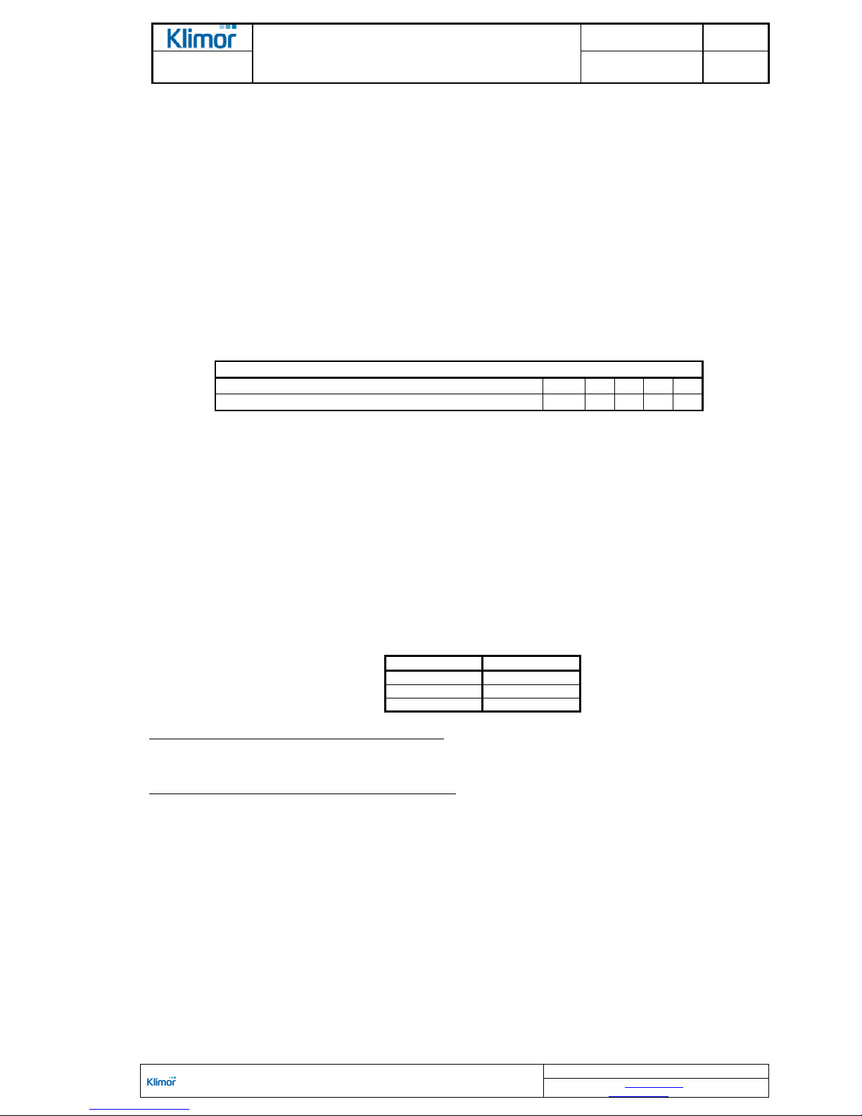
The MCK AHUs as a standard are produced in the following sizes, air flow rates and air compression ratios
Table No. 1 Basic AHU parameters
Size of AHU
01 02 03 04 05 06 07 08 09 10 11
Width
[mm]
715 715 1020 1020 1325 1740 1740 2240 2240 2240 2850
Height
540 740 740 1040 1040 1040 1440 1440 1740 2240 2240
Min air flow
[m3/h]
500 1350 2050 3000 4000 5500 8000 10500 12500 16500 21000
Optimal air flow
1830 3790 5620 8340 11240 13960 18810 26380 32770 45960 59150
Max air flow
3600 5400 8100 14000 18500 24500 35000 46000 56500 74000 100000
ΔP
–
available pressure: 0 ÷ 2000 Pa
Selection of AHU size is dependent on the air flow through the filters, cooler, humidifier, AHU pressure drop and
noise level. It is possible to deliver AHUs with different air flow and compression ratio than those listed in the
Table No. 1. The air flow figures listed above are related to the AHU window.
OPERATION AND MAINTENANCE MANUAL DTR MCK v.2.4
PAGE
GDYNIA
MODULAR AIR HANDLING UNITS
MCKS, MCKH, MCKP
2017 EN 4/45
KLIMOR Spółka z ograniczoną odpowiedzialnością Sp.k., 81-035 Gdynia, ul. B. Krzywoustego 5
Fax: (+48 58) 783-98-88; Tel.: (+48 58) 783-99-99
Service - Fax: (+48 58) 783-98-88; Tel.: (+48 58) 783-99-50/51 Mobile: (+48) 510 098 081
Information in this document is subject to change
email: klimor@klimor.pl - office
serwis@klimor.pl - service
In case of water heater it is recommended not to exceed 5 m/s at the heat exchanger window and 4 m/s for coolers.
2.2.2 Optimal parameters of heating, cooling and humidifying mediums
Table No. 2 Medium
parameters
Parameters
Unit Value
DX evaporation temperature
°
C
+5
Cooling water temperature (glycol solution) at the inlet:
- min
°
C
+2
- max
°
C
+12
Max temperature/pressure of heating water:
- hot
°
C/MPa
95/0,6
- overheated
°
C/MPa
130/1,6
Max temperature of heating steam
°
C
150
Water pressure – water humidification
MPa
0,15÷1,0
Water pressure – electrical steam generator
MPa 0,1÷0,6
Recommended available pressure:
- for water cooler with a control node MPa 0,05÷0,1
- for water heater with a control node MPa 0,01÷0,05
2.2.3. MCK AHU designation method
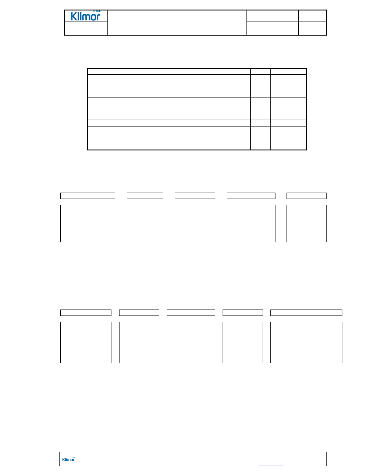
The MCK AHUs as standard are designated with a short code, according to markings shown in the diagram 1.
Diagram No. 1 Short MCK AHU designation
1 2 3 4 5
TYPE:
MCKS – standard
MCKH – hygienic
MCKP – swimming
pool
SIZE:
01
-
11
AIR
FLOW
V/100*
AVAILABLE
PRESSURE
ΔP/10*
SIDE VER-
SION
R – RIGHT
L – LEFT
*) value of air flow rounded up, value of available pressure rounded down
EXAMPLE: the MCK AHU – standard right version, size 5, air flow: 10.000 m3/h, available pressure: 500 Pa
MCKS0510050R
Complete designation of the MCK AHUS contains also codes of combined air handling sections.
Diagram No. 2 Extended MCK AHU designation
1 - 5 - 6 +
7 +
8 +
9
VERSION
SIZE
AIR FLOW
AVAILABLE
PRESSURE
VERSION SIDE
SECTION
CODING:
ACC. TO Ta-
ble No. 3
AD
SHUT OFF
DAMPER
CONTROL
FC
FLEXIBLE
CONNEC-
TION
OPTIONS
O – external version
A – control system included
EXAMPLE: the MCK AHU in standard right-side version with complete control system, size 5, air flow: 10.000 m3/h,
available pressure: 500 Pa, equipped with the cartridge filter, water heater, water cooler, fan, silencer and connectors.
MCKS0510050R-PFWHWCVFSL+AD+FC+A
EXAMPLE: the MCKH AHU in external hygienic right-side version with complete control system, size 5, air flow:
10.000 m
3
/h, available pressure: 500 Pa, equipped with the cartridge filter, water heater, water cooler, fan, silencer,
secondary filter and connectors.
MCKS0510050R-PFWHWCVFSLSF+AD+FC+O+A
OPERATION AND MAINTENANCE MANUAL DTR MCK v.2.4
PAGE
GDYNIA
MODULAR AIR HANDLING UNITS
MCKS, MCKH, MCKP
2017 EN 5/45
KLIMOR Spółka z ograniczoną odpowiedzialnością Sp.k., 81-035 Gdynia, ul. B. Krzywoustego 5
Fax: (+48 58) 783-98-88; Tel.: (+48 58) 783-99-99
Service - Fax: (+48 58) 783-98-88; Tel.: (+48 58) 783-99-50/51 Mobile: (+48) 510 098 081
Information in this document is subject to change
email: klimor@klimor.pl - office
serwis@klimor.pl - service
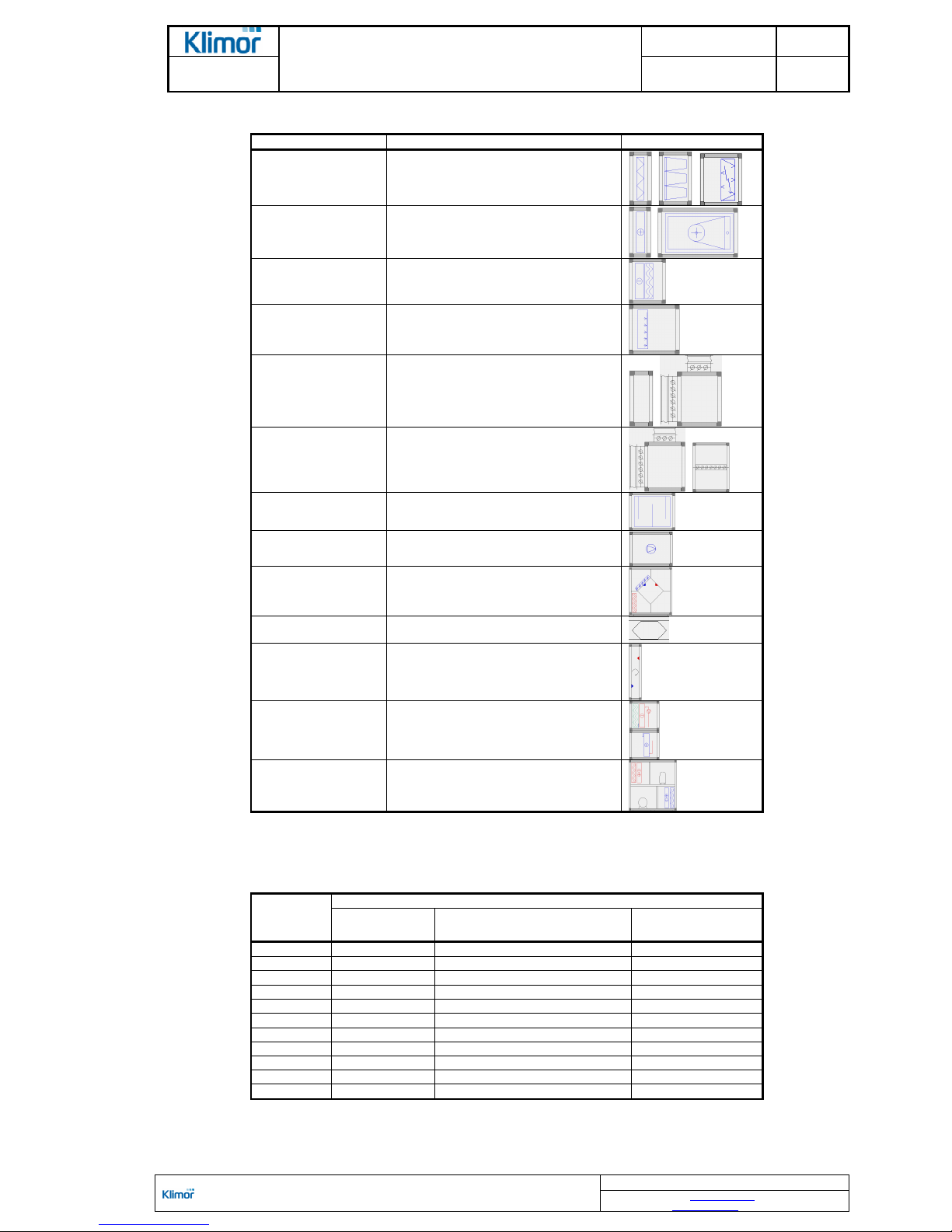
Table No. 3 Symbols and section code designations
Module designation
Name
Figure
PF
SF
EF
Cartridge filter
Bag filter
Electrostatic filter
WH
EH
MG
Water heater
Electrical heater
Gas heater
WC
DX
Water cooler
DX cooler
HS
Steam generator
Steam humidification
Water humidification
ES
Inspection
Mixing
Separation
MX
Mixing
Recirculation
SL
Short silencer
Long silencer
VF Fan
PR Cross-flow heat exchanger
CPR High-performance hybrid exchanger
RR Rotary heat exchanger
RG Glycol system
CM
HPM,
HPM-BPS
Cooling module
Heat pump
2.2.4 Dampers and connectors table
Table No. 4 Dampers and connectors sizes
AHU size
Designations and size of connectors and dampers
Size V2;H2
–
at
the cover
Size 3 – at whole frontal
surface
Size 21 – at whole
AHU cover
01
400×250 635×440 400×250
02
400×315 635×640 400×315
03
630×315 940×640 630×315
04
630×410 940×940 630×410
05
1000×410 1245×940 630×410
06
1250×410 1640×940 630×410
07
1250x630 1640×1340 1250×630
08
1600×630 2140×1340 1250×630
09
1800×810 2140×1640 1600×630
10
1800×1010 2140×2140 1800×1010
11
2200×1010 2750×2140 1800×1010
V – location at the vertical cover
H – location at the horizontal cover
OPERATION AND MAINTENANCE MANUAL DTR MCK v.2.4
PAGE
GDYNIA
MODULAR AIR HANDLING UNITS
MCKS, MCKH, MCKP
2017 EN 6/45
KLIMOR Spółka z ograniczoną odpowiedzialnością Sp.k., 81-035 Gdynia, ul. B. Krzywoustego 5
Fax: (+48 58) 783-98-88; Tel.: (+48 58) 783-99-99
Service - Fax: (+48 58) 783-98-88; Tel.: (+48 58) 783-99-50/51 Mobile: (+48) 510 098 081
Information in this document is subject to change
email: klimor@klimor.pl - office
serwis@klimor.pl - service
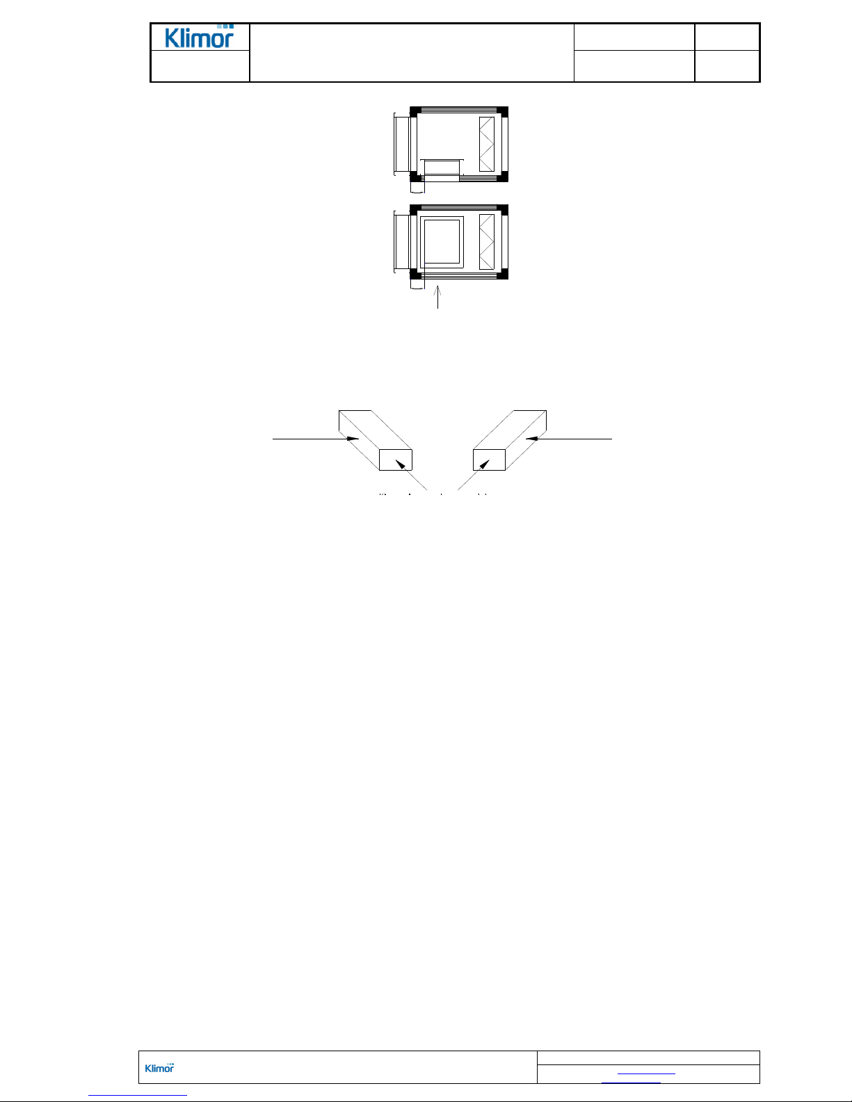
100
100
Strona obsługi
Figure No. 1 the connectors and dampers in the AHU in version with a damper located inside and outside.
2.2.5 AHU version
Figure No. 2 AHU version
2.3 AHU construction
2.3.1 AHU structure
AHUs and AHU sets are combined from functional modules which are also called "sets". A designer choose the set's
arrangement according to the requirements of air handling at a particular site.
Main elements of single sets:
- skeleton-based supporting structure
- functional sets
- casing components
- AHU framework
The skeleton is made of aluminum profiles connected at corners, using special fasteners made of construction material. Separating frames called „ribs” are stiffeners and they are made of aluminum profiles. At the same time they are
a supporting structure for individual functional sets installed inside the AHU.
Dismantling, opening, disassembling or cutting out elements of the supporting structure carried out by the
user may lead to the AHU depressurization and loss of warranty.
The supporting structure with ribs and the equipment installed inside, as individual functional sets, is enclosed with
sandwich-like panels: covers, lids and doors. The panels are made of external and internal sheets and space between them is filled with nonflammable mineral wool. They are made of galvanized sheet or coated galvanized sheet.
To facilitate access to the AHU components all operational panels as well as some back panels are removable.
Joints of a lid or door with the structure are sealed with a rubber sealing attached to a profile lip.
Top, bottom covers as well as panels situated opposite to the operational AHU side are riveted to the skeleton.
The AHU skeleton in situated on the AHU framework made of a bended channel bar attached to it with bolts. A
shock-absorbing spacer is installed between the skeleton and the framework. In case of AHUs size 1÷3 base frame
corners are used instead of the framework. In the framework and foundation corner joints there are Ø50 holes for
hook attachment or leading through a cross-bar.
The AHUs are equipped with pulse connectors for connecting the filters and fans pressure gauges.
service side
service side service side
left-hand version
right-hand version
air flow direction

OPERATION AND MAINTENANCE MANUAL DTR MCK v.2.4
PAGE
GDYNIA
MODULAR AIR HANDLING UNITS
MCKS, MCKH, MCKP
2017 EN 7/45
KLIMOR Spółka z ogr aniczoną odpowiedzialnością Sp.k., 81-035 Gdynia, ul . B. Krzywoustego 5
Fax: (+48 58) 783- 98-88; Tel.: (+48 58) 78 3-99-99
Service - Fax: (+48 58) 78 3-98-88; Tel.: (+48 58) 78 3-99-50/51 Mobile: (+48 ) 510 098 081
Information in this document is subject to change
email: klimor@kli mor.pl - office
serwis@klimor.pl - service
2.3.2 Functional sets
Depending on the functional requirements related to the air handling process the AHUs are equipped with the following batch sets:
2.3.2.1 PF filtering block and MX mixing (recirculation)
In the PF preliminary filtering block the G2÷M5 grade cartridge filter or G4 and M5 bag filter is installed.
A task of this block is to clean and mix an air (in case of the recirculation).
The G2-class filters are metal filters for preliminary removing oily slurries from air.
The G2÷M5-class cartridge filter assembly method enables its easy replacement or regeneration.
In order to disassemble the filter remove the cover or open the door and slide out the filter from the guide.
A new cartridge filter should have a self-adhesive sealing attached.
Bag filters are attached in guides and pushed against the sealing with a flat bar with an eccentric joint. Bag filter replacement procedure is shown in the Fig. No 36. While replacing the filter it is also recommended to replace the
guide sealing.
Dimensions of applied filters are listed in the KT certificate and in the rating plates.
The MX mixing sets are used in air supply AHUs. These sections are equipped with two dampers.
The MX recirculation sets are used in air supply/exhaust AHUs. These sections are equipped with a recirculation
damper and optional cut-off damper.
In the PR cross-flow heat exchanger section the PR recirculation damper is installed directly at the heat exchanger
bypass channel and it does not require application of an additional chamber.
Under the MX block there is located a drip tray with a connector to drain off the condensate, led to the operational
side. In case of the AHU size 11 there is also provided another connector leading to the opposite side.
Drain traps are also provided and please make sure to install them in accordance with the guidelines listed in the
point 6.2.5
All AHU rectangular inlets and outlets are equipped with flexible connectors. They are screwed in to a damper or
AHU's covers. Size of flexible connectors and rectangular connectors for individual AHUs according to the Chapter
2.2.4.
The flexible joints are protected for transport using sheet strips. The flexible joint is equipped with yellow-green
ground lead, which should not be removed and it should be connected to the duct system.
Factory protecting elements of the filters should be removed once the AHU is positioned in the dedicated
operating location.
2.3.2.2 WH, EH and MG heating block
The task of this block is to heat up the air up to the temperature required according to the design data. This task is
accomplished using a water, electrical or gas heater.
Water heaters
Standard water heater consists of a galvanized steel sheet casing and CuAl package with copper pipes and aluminum fins. Manifolds and connectors are made of copper or steel.
The heat exchanger is equipped with plugs: drain plug and venting plug. During assembly of hydraulic system it is
recommended to install drain and vent valves at the pipes leading to the heat exchanger.
When connecting heater to the supplying system it is necessary to consider recommendations listed in the section 6.
Procedure of the heat exchanger disassembly:
- Once the medium supply and return line is cut off remove the heat exchanger panel on the operation side.
- When you remove fixing blots of the heat exchanger at
the operation side, slide out the heat exchanger from
the guides.
This method of the heat exchanger assembly enables their
free disassembly even if an access to the AHU is possible
just from one side. And the cover, if it is located on the back
AHU side, enables inspection without removing the heat exchanger.
Vertical heat exchanger components touching the AHU cover are equipped with a self-adhesive sealing.
Installation of the thermostat should be carried out with the
heat exchanger removed, before connecting the hydraulic
system of heating water.
Figure No. 3 Assembly of the heat exchanger in a block
1 - heat exchanger
2 - ribs of heat exchan ger
3 - guide
4 - AL rib
5 - service side pa nel
6 - self-tapping scre w 4.8x16
7 - gasket
OPERATION AND MAINTENANCE MANUAL DTR MCK v.2.4
PAGE
GDYNIA
MODULAR AIR HANDLING UNITS
MCKS, MCKH, MCKP
2017 EN 8/45
KLIMOR Spółka z ogr aniczoną odpowiedzialnością Sp.k., 81-035 Gdynia, ul . B. Krzywoustego 5
Fax: (+48 58) 783- 98-88; Tel.: (+48 58) 78 3-99-99
Service - Fax: (+48 58) 78 3-98-88; Tel.: (+48 58) 78 3-99-50/51 Mobile: (+48 ) 510 098 081
Information in this document is subject to change
email: klimor@kli mor.pl - office
serwis@klimor.pl - service
Electrical heaters
Electrical heaters installed in the AHUs can be single- or multi-step units with different power division for each stage.
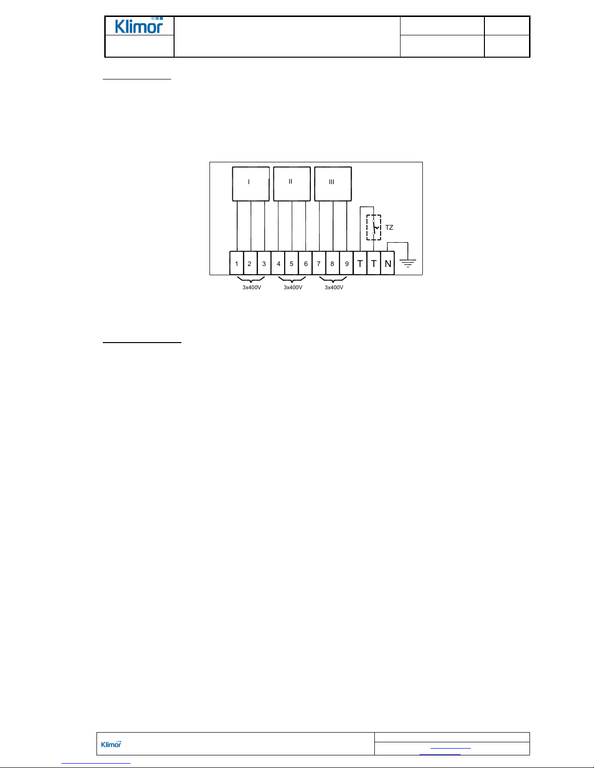
Heaters are equipped with radiator heating elements with large heat exchange area. By factory default they are connected to the terminal strip.
A choke is installed in the heating block cover and it enables leading through the heater power lead.
The diagram showing connection of heating elements to the terminal strip is attached to the casing.
The electrical heaters are equipped with a thermal trip switch protecting the device from overheating when the air flow
is stopped. Such trip switch with opening contacts should be considered in the control system plan.
T T N
T
Z
III
I
I
SEKCJ
A
SEKCJ
A
I
SEKCJ
A
1 2 3 4 5 6 7 8
9
3x400
V
stopień I
stopień I
I
3x400
V
3x400
V
stopień III
Figure No. 4 Example of connecting heating elements and a thermostat to the terminal strip in the 3-stage heater
Gas heating module
Gas heating module with gas burners enables heating up flowing air at the exhaust gases/air-type heat exchanger.
The "gas heating module" concept is related to the complete AHU block realizing this function. The MG heating model installed in the AHUs, among others, consists of the exhaust gases/air heat exchanger, fan burner, gas supply
path, pipe for connecting fume release funnel, pipe for releasing condensate and protecting automatic control system.
Applied standard fan burners are available in a modulated version.
Due to operation safety each type of the heating module has got a certain min and max air flow and min and max
power output of each burner. These data can be found in the burner's OMM supplied along with the AHU as well as
in the AHU technical data sheet. If these recommendations are not followed, the device may be damaged.
For AHUs with the heat recovery the heating module sections can be equipped with internal bypass chambers of the
heat exchanger with a control damper. The side flow is used in case of devices with air flow higher than acceptable
amount of air flowing through the heat exchanger. Amount of the bypass air is listed in the AHU technical data and
enables correct damper adjustment with the manual setting. The fan burner and the protecting control system switchboard are installed at the casing's wall and they are protected with a deflected cover. External AHU versions also use
a solution with the heat exchanger and burner, fan burner and protecting control system's switchboard built-up inside
the section. Then all equipment is installed inside the section with free access from the operation side.
The heating module requires connection of the gas supply to the burner (gas path) and funnel for releasing fumes as
well as the condensate release system.
Gas heating module is a source of radiant heat and high temperature that appears at the time of air flow suddenly
stop. Therefore, for the protection of devices installed in the air flow in AHU and in the duct after AHU, security zones
are required. Inside AHU the gas module is empty section with a length of 750 ÷ 1000 mm depending on the type and
size of the module. The same is the length of an empty section after the gas module in the case of the other functions
of AHU. If gas module is the last section of the AHU, you must also provide a minimum distance of 500 to 750 mm to
mounting devices (e.g. silencers). This distance can provide duct reducer.
Observe required and recommended air flow amounts through the heat exchangers and bypass. Do not
change or adjust the heat exchanger bypass damper opening level during operation of the gas heating modules.
Burners are supplied with IIe2 (GZ50), LW (GZ41,5); LS (GZ35) and 3PB/P (LPG) gas.
Gas type has to be specified at the unit selection and must be specified in the order.
In case of external AHUs movable shields or roofing are used as a protection against rain and UV.
The MG gas heating modules are supplied with a separate additional operation and maintenance manual
(OMM). When starting the device strictly follow all instructions and precautions contained within.
Information related to the burner start-up are also provided in the section 6.2.3.
SECTION SECTION SECTION
STAGE I STAGE II STAGE III
OPERATION AND MAINTENANCE MANUAL DTR MCK v.2.4
PAGE
GDYNIA
MODULAR AIR HANDLING UNITS
MCKS, MCKH, MCKP
2017 EN 9/45
KLIMOR Spółka z ogr aniczoną odpowiedzialnością Sp.k., 81-035 Gdynia, ul . B. Krzywoustego 5
Fax: (+48 58) 783- 98-88; Tel.: (+48 58) 78 3-99-99
Service - Fax: (+48 58) 78 3-98-88; Tel.: (+48 58) 78 3-99-50/51 Mobile: (+48 ) 510 098 081
Information in this document is subject to change
email: klimor@kli mor.pl - office
serwis@klimor.pl - service
2.3.2.3 HS humidification block
The task of this block is air humidification at the level of required relative humidity. This task is accomplished using
water or steam.
The AHUs can be equipped with three types of humidifiers:
Water humidifier
–
trickling filter (sprinkling bed) supplied with tap water
The trickling filter is formed as a water circulation system. A catch box is located under the trickling filter and nonvaporized water as well as fresh water is gathered there. The float valve installed in the supply water system controls
an appropriate level of water in the reservoir. The circulating pump controls the water flow – some amount of water is
supplied to the trickling filter and the rest is supplied to the runoff. It ensures exchange of water in the reservoir as
well as cleaning the reservoir and the filter surface.
In order to ensure appropriate water flow through the humidifier it is necessary to maintain a required pressure of
supplying water. The humidifier operates at the range of 1÷10 bar of water pressure. The humidifier capacity depends
on this parameter and that's why the pressure value must be maintained at a level which has been determined when
the humidifier was selected.
Requirements related to the water humidifier installation are provided in section 6.2.4.
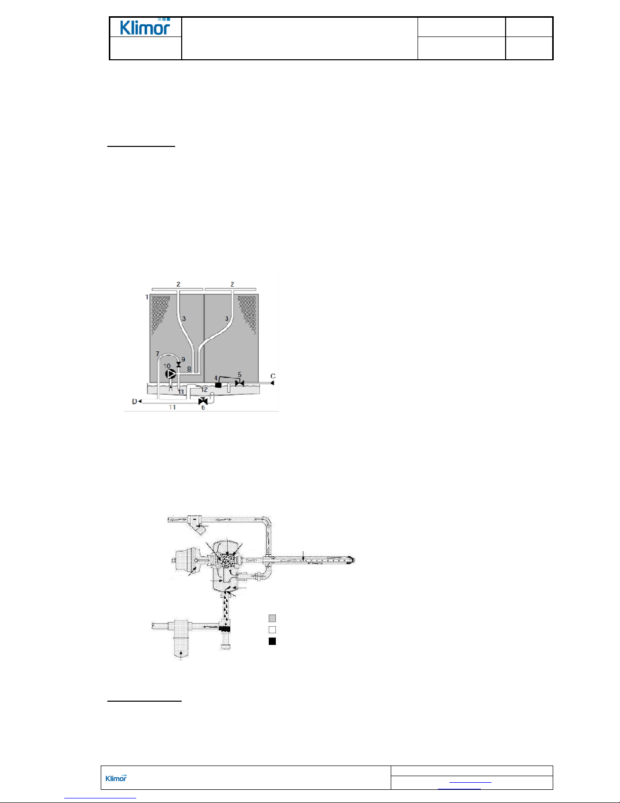
1. Trickling filter
2. Water distributors
3. Water distributors pipes
4. Float
5. Float valve
6. Manual drain valve
7. Water drain pipes
8. Supply manifold
9. Water drain control valve
10. Circulation pump
11. Outlet pipe
12. Water overflow outlet
13. Pressure protection
C. Water supply
D. Water outlet
Figure no 5 Water humidification system with trickling filter diagram
Steam humidifier – the humidifier using process steam
The steam humidifiers use process steam created at the site. The humidifier capacity mainly depends on this steam
pressure and that is why it is necessary to provide appropriate pressure in order to achieve required capacity. The
supply steam pressure should be determined at the AHU ordering stage. The humidifier can work at gauge pressure
of 0,15 to 4 bar.
1. strainer filter
2. dosing valve
3. drying chamber
4. noise dampening structure
5. steam lance with steam jacket
6. actuator
7. partitions
8. outlet
9. separation chamber
10. reverse dehydrator
Figure No. 6 Construction of the process steam humidifier
Operation principle:
The supply steam flows through a strainer and external part (so called "jacket") of the humidifier lance. It ensures appropriate lance temperature and heating, preventing steam condensation on a cold surface. The steam is provided
from the lance to the humidifier distributor, where it is dried and injected into the lance which is controlled by the metering valve. Adjustment of steam amount is a continuous process and it is controlled by the valve actuator. The condensate from dried steam flows off through the dehydrator to the system.
1
3
4
2
6
7
5
9
8
KEY
steam supply at su pply pressure
steam at atmospheri c pressure
condensate
10
OPERATION AND MAINTENANCE MANUAL DTR MCK v.2.4
PAGE
GDYNIA
MODULAR AIR HANDLING UNITS
MCKS, MCKH, MCKP
2017 EN 10/45
KLIMOR Spółka z ogr aniczoną odpowiedzialnością Sp.k., 81-035 Gdynia, ul . B. Krzywoustego 5
Fax: (+48 58) 783- 98-88; Tel.: (+48 58) 78 3-99-99
Service - Fax: (+48 58) 78 3-98-88; Tel.: (+48 58) 78 3-99-50/51 Mobile: (+48 ) 510 098 081
Information in this document is subject to change
email: klimor@kli mor.pl - office
serwis@klimor.pl - service
Humidifier with an electrical steam generator
The humidifiers with electrical steam generator use passage of current between electrodes immersed in water, to
heat up water and generate water steam. To enable passage of current between the electrodes, it is necessary to
use water containing mineral elements. The recommended composition of the water:
Required water parameters:
pH reaction: 7÷8.5
- conductivity: 350÷1250 uS/cm
- hardness: 100÷400 mg/l CaCo3
- iron and magnesium: 0,2 mg/l Fe+Mg
- silica: max 20 mg/l SiO2
- no organic contamination
- supply pressure: 1÷6 bar
- temperature: 1÷40°C
- water flow according to requirements of a particular generator
Higher concentration of mineral elements in water will lead to premature damage of electrodes and lower
concentration will cause drop of capacity of the steam generator
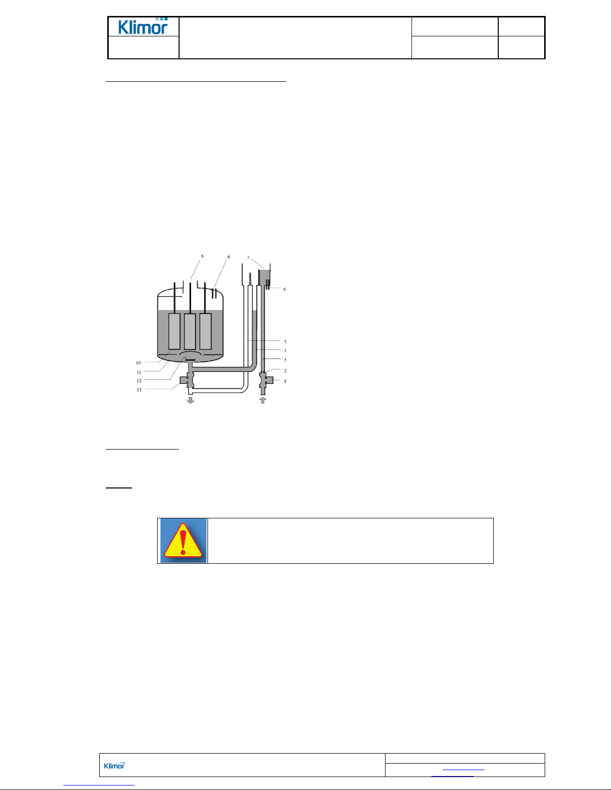
1. Supply solenoid valve
2. Flow limiter
3. Supply pipe
4. Filling pipe
5. Overflow pipe
6. Electrodes for conductivity measurement
7. Supply reservoir
8. Protection against excessive water level
9. Steam output
10. Electrodes
11. Cylinder
12. Water filters
13. Drain solenoid valve
Figure No. 7 Construction of the electrical water steam generator
Operation principle:
Once the supply valve is opened water flows through the supply reservoir into the cylinder. Once the cylinder is filled
the electrodes are heated and steam generation proceeds. Required steam generator capacity is achieved by setting
with the automatics control system an appropriate value of the current passing through the electrodes.
NOTE!
Type of a steam generator, amount and size of lances – all these parameters are determined individually for
a particular AHU and required amount of steam.
Method of starting up and operating humidifiers (water humidifiers, process
steam humidifiers and electrical steam generators) should be carried out
based on the instructions supplied by the humidifier manufacturer.
2.3.2.4 WC, DX cooling block
The task of this block is to lower the air temperature down to the temperature required according to the design data.
This task is accomplished by the water cooler, glycol cooler or direct expansion cooler (DX).
Standard cooler consists of a galvanized steel sheet casing and CuAl package with copper pipes and aluminum fins.
Manifolds and connectors are made of copper or steel.
The water and glycol exchanger is equipped with plugs: drain plug and venting plug. During assembly of hydraulic
system it is recommended to install drain and vent valves at the pipes leading to the heat exchanger.
When connecting coolers to the supplying system it is necessary to consider recommendations listed in the section 6.
A droplet separator is installed downstream the cooler to catch water drops.
In sectional coolers, in versions with double exchangers, the droplet separator is installed downstream the second
cooler.
Under the cooling block there is located a drip tray with a connector to drain off the condensate, led to the operational
side. In case of the AHU size 11 there is also provided another connector leading to the opposite side.
Drain traps are also provided and please make sure to install them in accordance with the guidelines listed in the
point 6.2.5
A cooler assembly and disassembly method in the AHU acc. to Fig No. 3.
OPERATION AND MAINTENANCE MANUAL DTR MCK v.2.4
PAGE
GDYNIA
MODULAR AIR HANDLING UNITS
MCKS, MCKH, MCKP
2017 EN 11/45
KLIMOR Spółka z ogr aniczoną odpowiedzialnością Sp.k., 81-035 Gdynia, ul . B. Krzywoustego 5
Fax: (+48 58) 783- 98-88; Tel.: (+48 58) 78 3-99-99
Service - Fax: (+48 58) 78 3-98-88; Tel.: (+48 58) 78 3-99-50/51 Mobile: (+48 ) 510 098 081
Information in this document is subject to change
email: klimor@kli mor.pl - office
serwis@klimor.pl - service
2.3.2.5 VF fan block
The task of this block is to force the air flow with a specific output and pressure.
The fan's power feed comes directly from the electric motor's shaft through the frequency converter (inverter).
Motor power: 1×230V or 3×400V 50/60Hz.
We use PF-type (plug-fan) fans without casing, with direct fan drive, with steel sheet or plastic rotors as well as direct
drive fans with EC motors.
The fan assembly is attached to a frame and it is fitted to the floor with shock absorbers. The fan's inlet flange is connected to a suction chamber diaphragm with a flexible connector or rubber sealing. The flexible connector and rubber
sealing eliminates transmission of vibrations.
In case of smaller fans the inlet funnel is attached independently to the section diaphragm.
AHUs dedicated for external operation are equipped with the service switch which provides ON/OFF signal to the
AHU's control system.
Max. air temperature during the AHU operation is +60°C. Due to permissible operating temperature of the electric
motor, a power drop has to be considered in accordance with the following table.
Table No. 5 Power correction factor for electric motors, depending on the ambient temperature
Power correction factor depending on the ambient temperature
Max °C ambient temperature 40 45 50 55 60
P/PN % 100 97 93 87 82
2.3.2.6. SF fine filtration block
The task of this block is very thorough air filtration with the F-class bag filter (F7 ÷ F9).
The bag filters are fitted in rails with gaskets and a strip clamp fasten with an eccentric connection mechanism. At the
filter replacement it is recommended to replace self-adhesive gasket attached inside the rail.
The S-class bag filters (H13÷H14) are attached in frames and they are pressed against them using the gasket and
bolt clamps.
Dimensions of applied filters are listed in the KT certificate and at next pages of this OMM.
Electrostatic EF filters can be used as higher class filtration elements. Filtration efficiency and class depends on the
air flow in the filter window. The table below lists possible filtration classes.
The EF filters require 230V/50Hz power supply for so called generators.
Table No. 6. Electrostatic filter classes depending on the air flow in the filter window
Air flow m/s Filtration class
≤ 3 EU7 (F7)
≤ 2.5 EU8 (F8)
≤ 2 EU9 (F9)
Electrostatic filters are composed of two main elements:
- filtration modules
- electronic module generating current with high voltage and very low current
Permissible operating conditions of the electrostatic filters:
- air flow temperature below 70°C
- air relative humidity at 15%÷98%
- size of eliminated particles: 0,01÷50 microns (it is necessary to install minimum EU4 class initial filter upstream the
electrostatic filter)
- no explosive components in the air being filtered
- no aluminum-corrosive components
Elements of electrostatic filters do not require replacement. They can be cleaned. The procedure is described
on next pages.
2.3.2.7 RR rotary heat exchanger block
In the RR assemblies heat recovery is achieved in a rotary heat regenerator, at 80% heat recovery efficiency. Removed warm air flows through a rotor's part and it heats it up. The rotating rotor transfers the heat from that heated
part to cold air in the air-supply part. In summer it is also possible to recover cool and humidity. Rotary heat exchangers can be used when some minor mixing of supplied and exhausted air is permissible.
There are available condenser heat exchangers for overt heat recovery as well as hygroscopic heat exchangers for
overt and latent heat recovery.
OPERATION AND MAINTENANCE MANUAL DTR MCK v.2.4
PAGE
GDYNIA
MODULAR AIR HANDLING UNITS
MCKS, MCKH, MCKP
2017 EN 12/45
KLIMOR Spółka z ogr aniczoną odpowiedzialnością Sp.k., 81-035 Gdynia, ul . B. Krzywoustego 5
Fax: (+48 58) 783- 98-88; Tel.: (+48 58) 78 3-99-99
Service - Fax: (+48 58) 78 3-98-88; Tel.: (+48 58) 78 3-99-50/51 Mobile: (+48 ) 510 098 081
Information in this document is subject to change
email: klimor@kli mor.pl - office
serwis@klimor.pl - service
The section consists of a rotary heat exchanger and driving mechanism. The casing has got an inspection panel enabling access to the rotor's driving mechanism.
The hygroscopic heat exchangers may have got a tray installed under the exchanger, located within the AHU frame
free space, with a connector leading to the operational side of the AHU.
The driving mechanism consists of a belt transmission, electric motor and motor base with self-adjusting belt tensioning function.
The electric motor is delivered with a 0,37kW; 1×230V/3×230V; 50Hz inverter.
The internal AHUs are equipped with Danfoss FC51 inverters and external AHUs are equipped with LG IC5 inverters.
Below you can find inverter settings for the 0÷10V signal control from an external source for both inverter types.
Wiring of inverters according to their respective OMMs.
If the AHU has been delivered together with the Klimor control system, do not use these settings. Please use information provided in corresponding control system OMMs.
Table No. 7 Basic parameters for programming Danfoss FC 51 inverter Settings for adjusting speed by analogue 0÷10V signal
Parameter no. Parameter name Setting Unit
QUICK
MENU 1
120 Motor rated power
According to the motor
rating plate kW
122 Motor rated voltage 230 V
123 Motor rated frequency 50 Hz
124 Rated current
Table No.
9 A
125 Motor rated RPM
Table No.
9
RPM
129 Auto matching with AMT motor Switch on [2] */
302 Min set Hz value
FZ min
Table No.
9
Hz
303 Max set Hz value FZ max
Table No.
9 Hz
341 Acceleration time in s - from min to max preset value 30 s
342 Breaking time in s - from min to max preset value 30 s
MAIN
MENU
190 Motor thermal protection ETR Trip 1 [4]
315 Source 1 of the set value 1
316 Source 2 of the set value 0
317 Source 3 of the set value 0
412 Motor low speed limit in Hz FZ min
Table No.
9 Hz
414 Motor high speed limit in Hz
FZ max
Table No.
9
Hz
416 Limit of torque in % 110 %
540 Relay function 6
610 Terminal 53 Low voltage level 0,07 V
611 Terminal 53 High voltage level 10 V
614 Terminal 53 Minimum set value 15 Hz
615 Terminal 53 Maximum set value 65 Hz
*/ Once this parameter is set to function [2] the PRESS HAND START message appear in the display. When the HAND START button on the control
panel is pressed, the converter proceeds with the auto matching.
When the auto matching is complete, press OK on the control panel and the parameter is automatically set to [0] value. Now you can proceed with the
programming.
Table No. 8 Basic parameters for programming LG IC5 inverter Settings for adjusting speed by analog 0÷10V signal
Code Name
Set point value
Description
H93 Restoring factory defaults 1 All parameters
drv Control mode 1 Switch ON - forward
Frq Frequency setting method 3 V1 terminal - 0÷10V
ACC Acceleration time 30s
dEC Stopping time 30s
F21 Max. output frequency Fz max Table
F22 Motor rated frequency 50 Hz
F23 Min requested frequency Fz min Table
F30 U/F characteristics 0 Linear
F50 Motor overload protection 1 Active
H30 Rated motor output ...kW Table No. 9
H33 Rated motor current ...A Table No. 9
I7 V1 min voltage input 0V
I8 Frequency for I7 input Fz min Hz Table No. 9
I9 V1 input max voltage 10V
I10 Frequency for I9 input Fz max Hz Table No. 9
I17 Determining P1 multifunction input function 0 Operation - forward
I55 Relay function 12 Operation without alarm
NOTE! The rotor drive motor has to be energized by an inverter in order to eliminate jerking a belt while starting and stopping the rotor.
OPERATION AND MAINTENANCE MANUAL DTR MCK v.2.4
PAGE
GDYNIA
MODULAR AIR HANDLING UNITS
MCKS, MCKH, MCKP
2017 EN 13/45
KLIMOR Spółka z ogr aniczoną odpowiedzialnością Sp.k., 81-035 Gdynia, ul . B. Krzywoustego 5
Fax: (+48 58) 783- 98-88; Tel.: (+48 58) 78 3-99-99
Service - Fax: (+48 58) 78 3-98-88; Tel.: (+48 58) 78 3-99-50/51 Mobile: (+48 ) 510 098 081
Information in this document is subject to change
email: klimor@kli mor.pl - office
serwis@klimor.pl - service
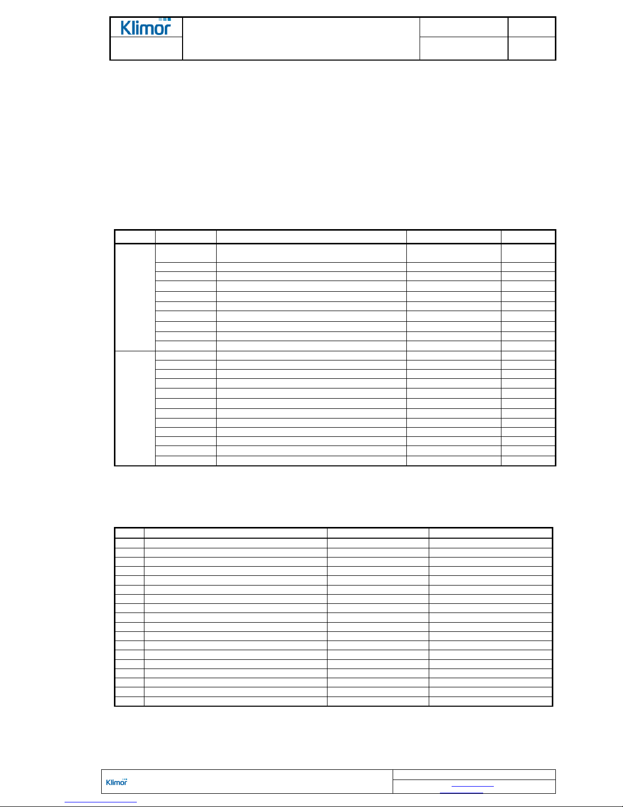
Table No. 9 The parameters required for correct setting of the rotor inverter
Rotor symbol
non-hygroscopic
Rotor symbol
hygroscopic
Min operation
frequency
of motor Fz min
[Hz]
Max motor operation frequency, FZ
max [Hz]
Rated motor
output
[kW]
Rated motor
RPM
[rpm]
Rated
motor cur-
rent
[A]
RR1_MCK01 RRH1_MCK01 5 47 0,06 214 0,4
RR1_MCK02 RRH1_MCK02 5 38 0,06 214 0,4
RR1_MCK03 RRH1_MCK03 5 38 0,06 214 0,4
RR2_MCK03 RRH2_MCK03 5 45 0,06 214 0,4
RR1_MCK04 RRH1_MCK04 5 50 0,06 214 0,4
RR2_MCK04 RRH2_MCK04 5 40 0,12 170 0,6
RR1_MCK05 RRH1_MCK05 5 50 0,06 214 0,4
RR2_MCK05 RRH2_MCK05 5 40 0,12 170 0,6
RR1_MCK06 RRH1_MCK06 5 40 0,19 170 0,8
RR1_MCK07 RRH1_MCK07 5 52 0,19 170 0,8
RR2_MCK07 RRH2_MCK07 5 40 0,19 170 0,8
RR1_MCK08 RRH1_MCK08 5 50 0,19 170 0,8
RR2_MCK08 RRH2_MCK08 5 50 0,19 170 0,8
RR1_MCK09 RRH1_MCK09 5 50 0,37 140 2,1
RR2_MCK09 RRH2_MCK09 5 50 0,37 140 2,1
RR1_MCK10 RRH1_MCK10 5 50 0,37 140 2,1
RR1_MCK11 RRH1_MCK11 5 50 0,37 140 2,1
RR2_MCK11 RRH2_MCK11 5 50 0,37 140 2,1
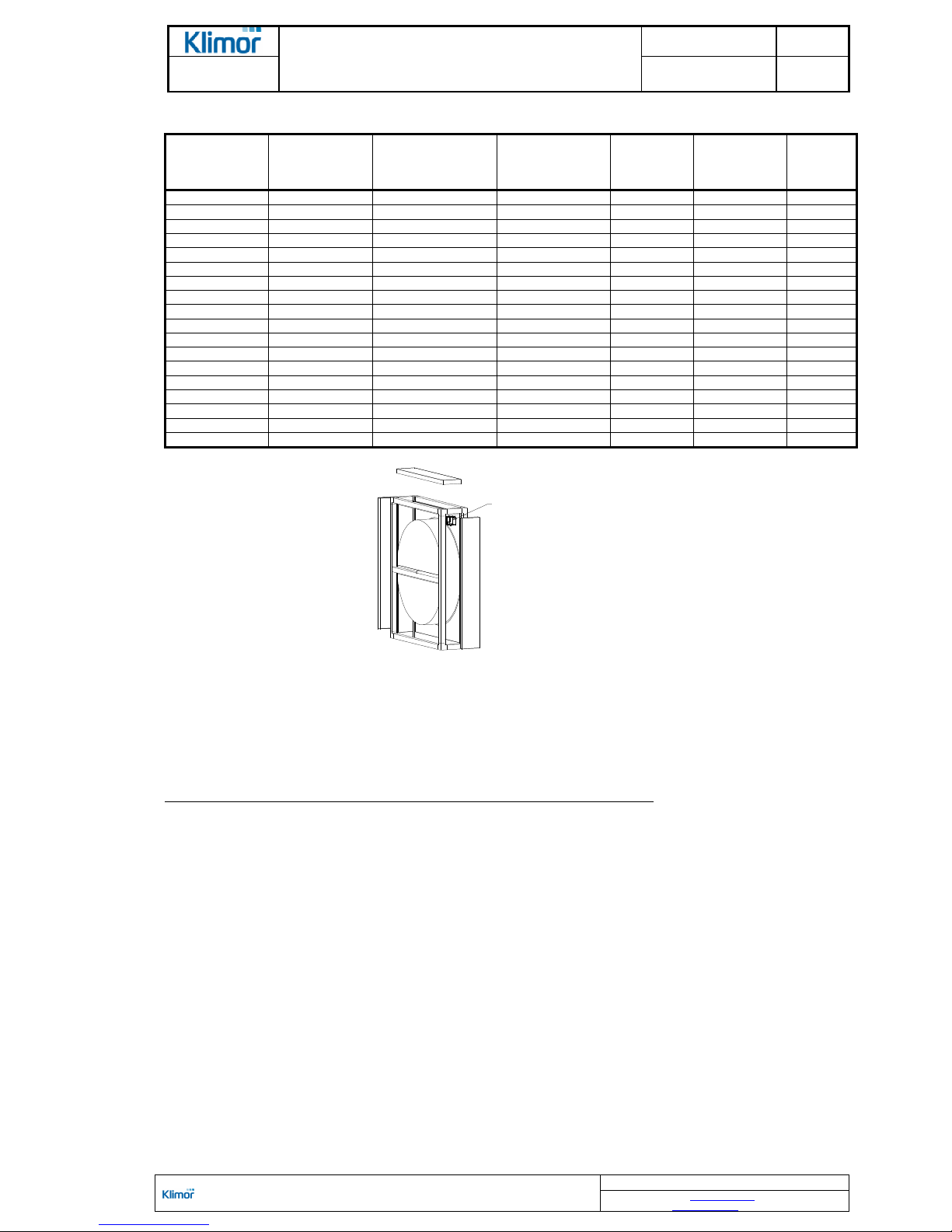
Figure No. 8 Recommended assembly of the inverter inside the rotor's block should be done according to the figure
The rotor is made of layers of aluminum foil wound over the rotation axis – alternately smooth and folded one, forming channels for air flow. In order to recover latent heat due to the humidity difference, the foil is additionally covered
with a layer of hygroscopic material.
The heat exchanger should be equipped with anti-frost system to protect the unit against consequences of extensive
chilling of the air exhaust part of the exchanger.
The protection system consists of (at a delivery of the control system manufacturer):
- sensor (pressure gauge) of pressure difference upstream and downstream the exhaust air exchanger,
Once the assumed pressure drop at the pressure gauge is achieved, a controller sends a signal to the heat exchanger due to frosting of the exchanger, to decrease in a stepless manner the rotor RPMs (system with a inverter).
NOTE! The rotary heat exchanger block as standard is delivered without the anti-frost system. Type of the
system is determined by an AHU or control system designer. Pressure system is recommended.
2.3.2.8.
PR cross-flow heat exchanger block and high-performance hybrid CPR heat recovery system
Application of the cross-flow heat exchanger ensures heat recovery from the exhaust air with up to 70% efficiency
(PR sets) and up to 90% in the high-performance hybrid heat exchangers (CPR sets).
Main system elements: cross-flow or high-performance cross-flow heat exchanger, by-pass, two-stage air damper,
drip tray and droplet separator.
The cross-flow heat exchanger is made of thin, pressed aluminum plates making up channels for supplied and exhausted air. A warm air stream extracted from a room flows through the heat exchanger channels and it heats up its
plates. The supply air stream flows perpendicular to the exhaust air stream, collecting heat from the heat exchanger's
plates.
Heat recovery with the cross-flow heat exchanger does not require providing external energy. The exchanger does
not feature moving parts such as, which makes it reliable and long-lasting. Supply and exhaust air streams are separated from each other and in a result humidity, odors and contaminations do not transfer the system.
location of frequency converter

OPERATION AND MAINTENANCE MANUAL DTR MCK v.2.4
PAGE
GDYNIA
MODULAR AIR HANDLING UNITS
MCKS, MCKH, MCKP
2017 EN 14/45
KLIMOR Spółka z ogr aniczoną odpowiedzialnością Sp.k., 81-035 Gdynia, ul . B. Krzywoustego 5
Fax: (+48 58) 783- 98-88; Tel.: (+48 58) 78 3-99-99
Service - Fax: (+48 58) 78 3-98-88; Tel.: (+48 58) 78 3-99-50/51 Mobile: (+48 ) 510 098 081
Information in this document is subject to change
email: klimor@kli mor.pl - office
serwis@klimor.pl - service
In the air exhaust section, downstream the heat exchanger there is located the droplet separator and drip tray with a
outlet connector on the operational side (AHU size 11
–
also on the other side).
Make sure to install a drain trap at the tank outflow connector, according to instructions listed in point 6.2.6
At the heat exchanger inlet there is a damper consisting of two sections: one at the exchanger and the other one at
the bypass. Both sections are coupled, so that at full air flow through the heat exchanger the exchanger's bypass
section is closed. And closing the heat exchanger opens the bypass section.
The bypass installed at the heat exchanger enables bypassing the exchanger by flowing air. Directing the air via the
bypass occurs in summer or when the heat exchanger anti-frost protection system is activated.
The anti-frost protection system prevents from excessive cooling down of the heat exchanger and from frosting the
heat exchanger air exhaust section.
The anti-frost protection system consists of:
- cross-flow exchanger damper actuator
- sensor of pressure difference upstream and downstream the exchanger,
- controller.
Once the presumed pressure drop at the pressure gauge is achieved due to frosting of the heat exchanger, the controller send a signal to the actuator – the damper at the heat exchanger is closed and the bypass air flow is opened.
This condition is maintained till the heat exchanger is warmed up and frost is melted. Since that time the heat exchanger damper starts to open, directing more and more fresh air through the heat exchanger.
NOTE! The cross-flow and high-performance hybrid heat exchanger block as standard is delivered without the anti-frost
system. Type of the system is determined by an AHU or control system designer. Pressure system is recommended.
2.3.2.9 Heat recovery block with intermediate medium
The set with the intermediate medium enables heat recovery at a level of 55% and in the high-performance set up to
70%. The set separates flow of exhaust air from supply air. It can also operate in separated air supply and exhaust
AHUs.
The set consists of two Cu-Al heat exchangers and the system with the circulating pump (option). Design of the heat
exchangers is similar to the Cu-Al water coolers and heaters.
A heat exchanger located in extracted airflow (cooler) absorbs the heat from the air and pass it over to the intermediate medium. Water solution of ethylene/propylene glycol is the intermediate medium, which circulates in pipes connecting both exchangers. The heat exchanger located in the supply airflow serves as a preliminary heater, passing
the heat over from the medium to the air. The heat exchanger located in the exhaust airflow (cooler) is equipped with
a droplet separator and the section is additionally equipped with the drain plate with an outlet connector on the operational side (also on the other side in AHUs size 11).
There are two possible system versions:
- Heat exchangers are installed in the NW AHU assembly set
The glycol system features a complete equipment: circulating pump, expansion vessel, pipelines, anti-frost system,
manometer, valves. The equipment is located outside and inside the casing and is arranged within a length of the set.
- Air supply AHUs and air exhaust AHUs are far from each other.
The heat recovery exchangers are installed in air supply and air exhaust AHUs.
The glycol system is located outside the AHUs. Depending on the pipeline length and system complexity, which influences the glycol flow resistance, power of the pump motors may be higher than those listed in the table above.
The system is made of welded PP pipes and in case of diameters over DN63 the system can be made of galvanized
screwed pipes.
In case of external AHUs the system made of plastic (also steel), if it is located outside the AHU casing, should be
protected using insulation of thickness defined in the PN requirements and should be coated with material UVresistant. The Klimor delivery does not contain such insulation.
In other cases the system made of plastic (and steel) does not require additional external insulation.
As standard the multi-level, centrifugal circulating pumps with constant-rotation motors are used. An inverter
(optional) is used to control of the pump output.
The internal AHUs are equipped with Danfoss FC51 inverters and external AHUs are equipped with LG IC5 inverters.
In case of external AHUs with piping located outdoors, it is necessary to protect the circulating pump and valves
against impact of low temperatures (insulations, shields – not provided by Klimor)
In the highest points of the system there are breathers.
Use seals made of aggressive glycol-resistant material.
The glycol system is equipped with anti-frost protection, which prevents from excessive temperature drop in the air
exhaust section.
The anti-frost protection system consists of:
- Pressure gauge (located at the glycol cooler)
- 230V 50Hz inverter
 Loading...