

Page 1
PACKAG E D T E R M IN AL
A IR C O N D ITI O N ER
Before using your air condition er, plea se read
this manual carefully and kee p it for future re ference.
Page 2
CONTENTS
1. SAFETY PRECAUTIONS..................................................................2
2. IMPORTANT SAFETY INSTRUCTIONS ..........................................4
3. AIR CONDITIONER FEATURES.......................................................5
4. CONTROL PANEL OPERATION.......................................................6
5. INSTALLATION .................................................................................7
6. CARE AND CLEANING......................................................................9
7. TROUBLESHOOTING.......................................................................10
R
ead This Manual
Inside you will find many helpful hints on how to use and maintain your air conditioner
properly. Just a little preventive care on your part can save you a great deal of time
and money over the life of your air conditioner. You'll find many answ ers to common
problems in the chart of troubleshooting tips. If you review our chart of Troubleshooting
Tips first, you may not need to call for service at all.
!
CAUTION
Contact the authorised service technician for repair or maintenance of this unit.
Contact the installer for installation of this unit.
The air conditioner is not intended for use by young children or infirm persons
without supervision.
Young children should be supervised to ensure that they do not play with the air
conditioner.
If the power cord is to be replaced, replacement work shall be performed by
authorised personnel only.
Installation work must be performed in accordance with the national wiring
standards by authorised personnel only.
NOTE:
All the illustrations in this manual ar e for explanation purpose only. Your air
conditione r may be slightly different. The actual shape shall prevail.
1
Page 3

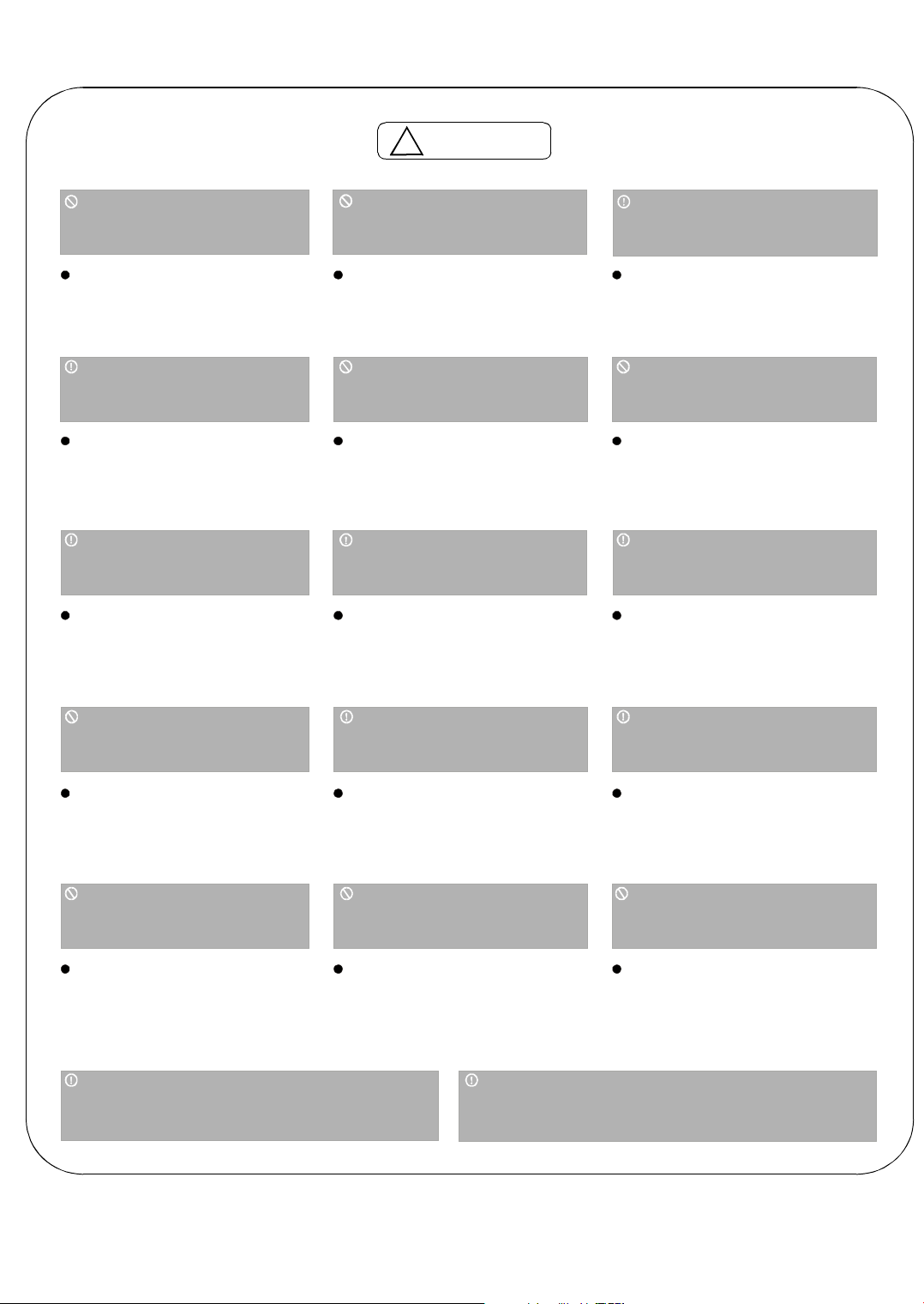
SAFETY PRECAUTIONS
To prevent injury to the user or other people and property damage, the following instructions
must be followed. Incorrect operation due to ignoring of instructions may cause harm or
damage. The seriousness is classified by the following indications.
WARNING
!
!
CAU TION
This symbol indicates the possibility of death or serious injury.
This symbol indicates the possibility of injury or damage to property.
Meanings of symbols used in this manual are as shown below.
Never do this.
!
Plug in power plug
properly.
Otherwise, it may cause electric
shock or fire due to heat
generation.
Do not modify power cord
length or share the outlet
with other appliances.
It may cause electric shockor
fire due to heat generation.
Always do this.
Do not operate or stop the
unit by inserting or pulling
out the power plug.
excess
It may cause electric shock or fire
due to heat generation.
Do not operate with wet
hands or in damp
environment.
It may cause electric shock.
WARNING
!
It may cause electric shock or fire.
If the power cord is damaged, it
must be replaced by the manufacturer or an authorised service
centre or a similarly qualified person in order to avoid a hazard.
This could damage your health.
Do not damage or use an
unspecified power cord.
Do not direct airflow at
room occupants only.
Always ensure effective
earthing.
Incorrect earthingmay cause
electric shock.
Unplug the unit if strange
sounds, smell, or smoke
comes from it.
It may cause fire and electric
shock.
Keep firearms away.
It may cause fire.
Ventilate room before operating air
conditioner if there is a gas leakage from
another appliance.
It may cause explosion, fire and, burns.
Do not allow water to run
into electric parts.
It may cause failure of machine
or electric shock.
Do not use the socket if it is
loose or damaged.
It may cause fire and electric
shock.
Do not use the power cord
close to heating appliances.
It may cause fire and electric
shock.
Always install circuit
breaker and a dedicated
power circuit.
Incorrect installation may cause
fire and electric shock.
Do not open the unit
during operation.
It may cause electric shock.
D o n o t u s e t h e p o w e r c o r d n e ar
fl a m m a b l e g a s o r c o m bu s t i b le s , s u ch
a s g a s o l i n e , b e n z e n e , th in n e r, e tc.
It may causean explosion or fire.
Do not disassemble or modify unit.
It may causefailure and electric shock.
2
Page 4
!
CAUTION
When the air filter is to be
removed, do not touch the
metal parts of the unit.
It may cause an injury.
When the unit is to be
cleaned, switch off, and turn
off the circuit breaker.
Do not clean unit when
power is on as it may cause
fire and electric shock, it may
cause an injury.
Stop operation and close
the window in storm or
hurricane.
Operation with windows
opened may cause wetting
of indoor and soaking of
household furniture.
Do not clean the air
conditioner with water.
Water may enter the unit and
degrade the insulation. It may
cause an electric shock.
Do not put a pe t or house
plant where it will be
exposed to direct air flow.
This could injure the pet or
plant.
Hold the plug by the head
of the power plug when
taking it out.
It may cause electric shock
and damage.
Ventilate the room well w hen
used together w ith a stove,
etc.
An oxygen shortage may occur.
Do not use for special
purposes.
Do not use this air conditioner to
preserve precision devices, food,
pets, plants, and art objects.
It may cause deterioration of
quality, etc.
Turn off the m ain power
switch when not sing the
unit for a long time.
It may cause failure of product
or fire.
u
Do not place obstacles
around air-inlets or inside
of air-outlet.
It may cause failure of
appliance or accident.
Do not use strong detergent such as wax or
thinner but use a soft cloth.
Appearance may be
deteriorated due to change
of product color or
scratching of its surface.
Use caution when unpacking and
installing. Sharp edges could cause injury.
E n s u re t h a t t h e i n s ta ll a t io n b r a c k e t of
t h e o u td oo r ap p l i a n c e is n o t d a m aged
du e to p ro lon g e d e x p o s u r e.
If bracket is damaged, there
is concern of damage due to
falling of unit.
D o n o t p la c e hea v y ob je ct o n the
p o w e r c o rd a n d e n su r e t h a t th e c o rd
is n o t c o m p r e ss e d.
There is danger of fire or
electric shock.
Always insert the filters
securely. Clean filter once
every two weeks.
Operation withou t filters may
cause failure.
Do not drink water drained
from air conditioner.
It contains contaminants and
could make you sick.
If water enters the unit, turn the unit off at the power
outlet and switch off the circuit breaker. Isolate
supply by taking the power-plug out and contact a
qualified service technician.
3
Page 5

IMPORTANT SAFETY INSTRUCTIONS
NO TE
this air cond itioner contains a current
detection devic e designed to reduce
the risk of fire.
Please ref er to the section Op eration
of Current Device for details.
In the event that the power supply
cord is damaged, it cannot be
repaired-it must be replaced with a
cord from the Product Manufacturer.
The power supply cord with
Do not, und er a ny
circ umstan ces, cut ,
remove , o r by pass
the grounding p ro n g.
Powe r s u pply cord
with 3-p rong gr oun di ng plu g
and current detection devi c e
WARNING
Do n ot store or use gasoline or other flammab le vapors and liquids in
the vicinity of this or any other appliance.
Avoid fire hazard or electric shock. Do not use an extension cord or an
adaptor plug. Do not remove any pron g from the power cord.
WARNING
Be sure the electrical service is adequate for the mod el you have
chosen. This informat ion ca n be fou nd on the serial plate, which
is located on the side of the cabinet and behind the grille.
Be sure the air con ditioner is properly grounded. To minimize
shock and fire hazard s, proper ground ing is important. The power
cord is equipped with a three-pr ong gro unding plug for protection
against shock hazards.
Your air conditioner must be used in a properly grounded wall
receptacle. If the wall receptacle you intend to use is not adequately
grounded or protected by a time delay fuse or circuit breaker,
have a qualified electrician install the proper receptacle.
Ensure the recep tacle is accessib le after the unit installation.
Do not run air conditioner without side protective cover in place.
This cou ld result in mechanical dam age within the air conditioner.
Do not use an extension cord or an adapter plug.
For your saf ety
El ect rical Infor mation
Oper ation of Current D evice
The power s upply cord contains a curren t device that sen ses damage to the power cord. To test your power
supply c ord do the follo wing:
1. Plug in the Air Conditioner.
2. The power supply cord will have TWO buttons on the plug head.
Pre ss the TEST button, you will no tice a click as the RE SET
button pops out.
3. Press the RESET button, again yo u will notice a click as the button
engages.
4. The power supply cord is now supplying electricity to the unit.
(On some products this it also indicated by a light on the plug head.)
NOTES:
Do not u se this dev ice to turn the unit on or off.
Always make sure th e RESET button is pushed in for correct operation.
The power supply must be rep laced if it fails reset when either th e TEST button is pushed, or it cannot be
res et. A new one can be obtained from the pr oduct manufacturer.
If power supply cord is damaged, it cannot be rep aired. It MUST be replaced by one
product ma nufacturer.
obt ained from the
4
Page 6

AIR CONDITIONER FEATURES
This unit has many featrues.The serv icer must be
familiar with these f eatu res in order to prope rly
service the unit.
Co mpresso r Restart Delay
Th is feature extends the overall li fe of compress or by preventing the short-cycling of the air
conditioner.When the compressor restarts,the
unit is desig ned to g ive a minim um of three
minutes to have a tim e of equalizing the ref ri gerant press ures for optimizing cycling.
Memory
Th e unit has memory . If pow er is lost,all of the
control settings(mode,fan speed ,on/off and
configuration) are remembered.So when power
is r estored,the unit will start back up in the mod e
(and config uration) it wa s in,whe n power was
lost.
Au tomatic Evapo rator Freeze P rote ct ion
Automatically to keep the e vaporator from
freezing,the comp ressor is tuuned off and the
indoor fan is turne d on when the eva po rator
te mperature is too lower.If the evaporator
te mperature is no t too lo we r this func tion is off.
Hi gh Temperature P rotection I n Heating
Op eratio n
Th e comp ressor an d(or) electric h eater will be
sw itched off to prevent dam age in high i ndoo r
blow air temper ature or error indoo r tempera ture
sensor.
Un it Configur ation
O O
F or C
Th e unit ca n displa y in eit he r F or C.
O O
Au tomatic Defro st Pro tectio n (for heat pump
mo dels only)
Wh en the outdoor tu be temper ature gets too
cold the unit will auto mati ca lly switch to ele ctric
heating and the compresso r will be off. The unit
will then heat with e lectri c heat until the outside
te mperature rises enoug h, so the compress or
can be used again .
Au tomatic Quick Warm -up (for heat pump
mo dels only)
If the room tempe ra ture falls to 4.5 C/8 F
O O
below the set point temperature,the revers e
cy cle heat is shut off and the electric st rip he at
is turned on for one cycle,un til heating is
satisfied.
LED Indicators and Buttons
The touch p ad has buttons fo r MODE ,FAN,
POWER,SETPOIN T UP and SETPOINT DO WN.
It al so has L EDs that correspond to th e mode,
fan speed,p ower a nd set point ope ra tion,to
ind icate the unit s status.LEDs for HI GH,MED
,
and L OW indicate the fan speed that is selected.
LED s for FAN,COOL and HEAT indica te wh at
ope ra ting m ode is active.LED for POWER i s the
uni t ON/OFF statu s LED.If the unit i s in ON mod e,
the LED will be green.If the unit is OFF,the LED
wil l be off.
NO TE:
HEAT mode is for Cooling & Heating models only.
5
Page 7

CONTROL PANEL OPERATION
The control pane l keypad will look like th e fo llowing
Fig .1:
HIGH MED LOW
FAN COOL HEAT
POWER
Fig.1
POWER
-
Press the POWER bu tton to turn the unit on or off.
When the unit is on,the power indicator light will be
green.Wh en the unit is off,the light will go out.
MODE
-
Push this button to cycl e th rough the mode s from
COO L-HEAT-FAN-CO OL.The indi cat or light beside
the "MOD E" option will illuminate, identifying the
mode selected.
- COO L :The rang e of se t te mp e rature is 17 C/62 F
O O
~30 C/86 F.Cooling begins au tomatically when the
room temperature is ab ove the se t point,and stops
when the room temperature is 2 C(4 F) below the
O O
O O
se t point.But the comp ressor will run 5 minutes at
least in COO L m ode before stoping. The fan runs
in continu ous m ode.
- HEAT:Th e range of set temperature is 17 C/62 F
O O
~29 C/84 F.For heat pump m o de ls,th e unit can
O O
alternate to run between in re vers e cycle h eat mode
and electric heater mode according to the difference
between the setting tem peratu re and the room
temperature.The fan m otor cycles on and off
with the compressor an d electric hea ter.
NOTE: The reverse cyc le and electric heater can
not be run at the same time.
- FA N:Fan ope ration only witho ut heating and cooling.
FAN (FAN SPEED)
-
Every time you push this bu tton,the fan speed
cycles through the se ttings a s follows:H IG H-MEDLOW-HIGH.
DISPLAYS:
--Show s the se t temperature in C or F. While on
O O
Fan only m ode,it shows the room tem perature.
Control code (on some models):
Pads on the control panel is no t availa ble .The
LC
unit ca n be se tted by using wire cot roller on ly.
Error codes:
Room temp erature sensor error;
AS-
Evapo rator te mperature sensor error;
ES-
Co ndense r te mp erature sensor error;
CS-
Ou tside temperature se nsor error;
OS-
Exhaust te mperature sensor error;
HS-
NOTE:When error occurs,un plug t he unit and plug
it back in.If error repeats, call for service.
Other codes:
Ro om temperature is lower than 0 C/32 F;
LO-
Room temper ature is higher tha n 3 7 C/99 F.
HI-
O O
O O
UP/DOWN BUTTONS ( / )
-
Push the UP (or DOW N) bu tton to increa se (or
decrease) th e set te mperature of the unit in coo ling
or heating mode.The te mperature can be se t by
increments o f 1 C (1 F) .The setting tem pe rature
O O
appears in th e display.
NOTE:Press and ho ld and butto ns toge ther
for 3 seco nds will altern ate the tem pe rature display
between C & F scale.
O O
6
Page 8

INSTALLATION
HOW TO INSTALL THE UNIT
CAUTION
!
The re are sha rp edges that ca n cause se rious c uts.
Wh en lifting the air cond itio ner,it is HEAVY.U se 2
peo ple to lift.
- For ex isting sleeve,you shou ld measure the wall
sleeve dimensions.
- In stall the ne w air conditioner according to these
installation instructio ns to achieve th e b est p erforman c e.
All wall sleeves used to mo unt the new a ir conditioner
must be in goo d structural con dition an d have a rear
grille that securely a ttaches to the sleeve or the flange
of the sleeve to secure the new air cond itioner.
- To av oid vibration and noise,make sure the unit is
installed s ecurely and firm ly.
- W he n ins talling the sleeve,make certain the re is
nothing w ithin 20 of th e back that would interfere
with heat rad iation a nd exhaust air flow. (See Fig.2)
COO LED
AIR
WALL
SLEE VE
HEAT
RA DIATION
INTAKE
Ov er 20
AIR
WALL
Dimens ion of air cond itioner
10 67m m/4 2i nch
40 8mm /1 6inc h
60 6mm/23 .9in ch
Dimens ion of slee ve asse mb ly (op tiona l)
106 7mm/42i nch
40 8mm /16inch
37 6mm /14 .8i nch
Shipping
tape
Fig.2
PREPARATION OF SLEEVE ASSEMBLY(optional)
- Refer to the installation instruc tion of sleeve assembly
for details.
PREPARATION OF REAR GRILLE ASSEMBLY(optional)
- Refer to the installation instruc tion of rear grille
assem bly for details.
UNIT INSTALLATION
-
- Then lift up .
- Carefully remo ve shipping tape s from the front panel.
(See Fig.3)
- Remove the front panel. (See Fig.4)
- Remove the shipp ing screw from the vent door.(Se e
Fig.5)
7
Fig .3
Pull o ut at the bottom to release it from the tab s .
Fig .4
Shipp ing
screw
Fig .5
Page 9

INSTALLATION CONTINUED( )
UNIT INSTALLATION (CONTINUED)
- Rotate the vent co nt rol lever to either open or cl ose
the vent d oor.(See Fig .6)
Vent con trol lever
Vent close d
Vent open
Fig .6
NO TE:When vent control lever set at CLOSE,on ly
the air inside the room is circulated an d filte red.
When set at OPE N ,som e outdoor air will be drawn
into room.This w ill reduce heat ing or cooling
efficiency.
- Lift u nit level an d s lide unit into w all sleeve u ntil
firmly ag ainst front of wall sleeve and secure w ith
4 screws and wash ers (supplied in the S LE EVE
AS SE MBLY ) throug h the unit flange holes.
(See Fig .7 an d Fig.8)
!
CAUTION
Do not put obstacles around air-inlet or
inside of air-outlet of the unit, such as window
curtain etc.
Always insert the filter securely, clean filter once
every two weeks as required.
Fig.7
Fig.8
- Reinstall front panel.(See Fig.9)
Place ta bs over top rail . Push Inwa rd at bottom
until pan el snap s into place .
Fig.9
8
Page 10

CARE AND CLEANING
FRONT PANEL AND CASE
- Turn unit off an d disconnect power supply.To clean,
use water an d a mild deterge nt. use bleach
and abras ive rs.Som e com mercial cleane rs may
damag e the plas tic parts.
OUTDOOR COIL
- Coil on outdoor side of unit shou ld be check ed
regularly.Unit will ne ed to be remo ved to inspe ct
dirt build-up tha t will occur on the inside of the c oil.
If clogge d with dirt and soo t ,coil s hou ld be
professionally cleaned. Clean inside and out side of
outdoor coils regularly.
NOTE:
UNIT DAMAGE HAZARD
Failure to follow th is cau tion ma y result in
equipm ent damge or improp er operation.
Airflow res triction ma y cause da mage to the unit.
AIR FILTERS
IMPORTANT:TURN UNIT OFF BEFORE
CLEANING.
UNIT DAMAGE HAZARD
Failure to follow th is cau tion ma y result in
equipm ent damge or improper operation.
Do not
becomes torn or d am aged,it sh ould be rep laced
immediately.
Operating without filters in place or with dama ged
filter wil l allow dirt and dust to reach indoor coil a nd
reduce cooling,he ating,airflo w and effic iency of unit.
Airflow res triction ma y cause da mage to u nit.
- The most important thing you can do to ma intain
unit efficien cy is to clean th e filters on ce ev ery
two w eeks as requ ired.
Clogged f ilte rs red uce cooling,heating and airflow.
-
Keeping filters clean will:
Decrease cost of op era tion.
Save energy.
Prevent clogge d ind oor coil.
Reduc e risk of prem atu re componen t fail ure.
-
To Clean Air Filters:
Vacuum off hea vy soil.
Run water through filter.
Dry thoroughly before rep lacin g.
Neve r use a hig h-p ressure spray on coil.
CAUTION
!
CAUTION
!
ope rate unit w ith out filters in place.If a filter
DO NOT
- Rem oving Air Filter
2 Air filters
Pull up
Fig .9
- Replacing Air Filter
Push do wn
Fig.10
VENT DOOR FILTER
IMPORTANT:TURN UNIT OFF BEFORE
CLEANING.
- If the vent do or is o pen,access requires the rem ov al
of the un it from the wa ll sleeve.C lea n the vent filter
twice a y ear or as requ ired.
- M ake sure to re mo ve the shipping sc rew from the
vent d oor.(S ee.Fig.5)
- Rotate the vent control lev er to o pen the ve nt door.
(See. Fig .6)
- Remove four screws from the ven t door filter.
(S ee .Fig.11)
- Fi rst pull out the ven t door steel w ire fro m the hole
of the vent do or, then take off the ven t door an d filter.
(See. Fig.11)
- Clean the filt er.D ry thoroug hly before replacing.
- Replac the vent door and filter,re install the four
screw s.
- Reinsert the vent do or ste el wire into the hole of the
vent d oor.
Vent door
control lever
.
Screws
Vent door
ste el wire
Ven t door
filter
Fig.11
Vent door
9
Page 11

TROUBLESHOOTING
UNIT DOES NOT START
Un it may have become unp lugged
Fuse may have blown
Circuit brea ker may have bee n tripped
Un it may be off
Un it may be in a pro tection mode.
UNIT NOT COOLING/HEATING ROOM
Un it a ir discharge section is blocked
Tem peratu re setting is not high or low
enough
Setpoin t limits m ay not a llow the
Note:
unit to heat or cool the room to the
tem perature desired. Check section on
dipswitch setting s.
Un it a ir filters are dirty.
Room is excessively hot or co ld when
unit is started.
Vent door left open.
Un it may be in a pro tection mode.
Co mp ressor is in time delay.
SOLUTONSPOSSIBLE CAUSES
Ch eck that plug is plugged securely in wall receptacle.
Plug ha s a test/reset button on it.M ake sure that the plu g has
Note:
not tripped.
Re pla ce the fuse.See N ote 1.
Re set circuit brea ker.See Note 1.
Turn unit on (bottom right butto n o n k eypad).
Ma ke sure tha t c urtains,blinds or furn iture a re not restricting or
blo cking unit airflow.
Re set to a low er or higher tem pera tur e setting.
Re move and clean filters.
Allow sufficient a mount of time for unit to heat or cool the room.Start
hea ting o r coo lin g early before outdoo r tempera ture,cooking heat or
gatherings of people ma ke room uncomfortable.
Clo se vent do or.
Ch eck dipswitch setting s fo r desire d com fort.
Wait approximately 3 m inutes for compre ssor to start.
DISPLAY HAS STRANGE NUMBERS/
CHARACTERS ON IT
UNIT MAKING NOISES
WATER DRIPPING OUTSIDE
WATER DRIPPING INSIDE
Wall sleeve is not installed level
ICE OR FROST FORMS ON INDOOR
COIL
Low ou tdoor temp erature
D irty filters
COMPRESSOR PROTECTION
Power may have cycle d,so c ompressor
is in a restart protection.
The unit ma y be in a protection mode.
The unit ma y be set for C (instea d of F).
Clicking,gurging and wh ooshing noises are no rmal during operation
of u nit.
If a dra in kit has not been insta lled,conde nsation ru noff during ve ry
hot an d hum id weat her is norm al.See Note 2.If a drain kit has been
ins talled and is c onnected to a drain s ystem ,che ck gaskets and
fitti ngs around drain for leaks and plugs.
Wall sleeve must be installed leve l fo r p rope r drainag e of
con densation .C heck th at installation is level an d m ake any
necessary ad justments.
Wh en outdoo r te mperature is approxi ma tely 55OF or below,frost
ma y form on the indoor coil when unit is in C ooling mo de.Swi tch unit
to FAN op eratio n un til ice or frost m elts.
Re move and clea n filters.
Random Compressor restart-
power ha s been restarte d,a random c om pressor re start will occu r.
After a power outage,the compressor will restart after approxi mately
3 m inu tes.
Compressor Protection-
the re is a random startu p d elay of 3 minu tes and a min im um
com pressor run time of 3 m inutes.
O O
Wh en ev er the unit is plugg ed in,or
To pr event short cycling of the compressor,
NOTES:
1.If circuit breaker is tripped or fuse is blo wn more than once,contact a qualifie d e lectrician.
2.If un it is installed where condensation drainage c ou ld drip in an un d esirable locat ion,an accessory dra in kit
should be installed and co nnected to drain system.
10
Page 12

The Klimaire logo is a registered Trademark of Klimaire Products inc.
Copyright 2010 Klimaire Products inc.
2190 NW 89 Place, Doral, FL 33172 - USA
Tel: (305)594-4972 Fax (305) 675-2212
www.klimaire.com sales@klimaire.com
The design and sp ecifications are subject to change with out prior notice for product
improvement. Consult with the sales agency or manufacturer for deta ils.
 Loading...