

Klimaire KSIE024TIR24H2 User Manual
o
r
a
e
e
W
a
l
o
c
h
i
n
l
l
r
N
o
e
i
u
o
s
A
e
C
a
r
a
D
h
u
t
C
o
y
a
e
o
a
w
c
e
a
u
o
p
0
9
t
r
i
y
:
D
1
T
1
U
8
h
e
e
u
a
h
P
G
1
G
2
2
8
f
C
d
e
u
H
A
R
4
H
8
8
1
w
t
s
h
M
I
M
0
C
E
L
LIG
IR
SE
T CO
COND
VICE
MER
TION
ANUA
IAL
R
Tab le
1. P
2. P
3. D
4. S
5. R
6.
7. F
8. E
9. S
10. A
11. T
12. F
13. I
14. E
15. E
16. T
17. D
f Content
ecaution
rt Names
imension
rvice spac
frigerant
iring Diagr
n Curves
ectric Cha
und Level
cessories
e Specific
eld Wiring
stallation
ectronic C
ectronic F
oubleshoo
isassembly
nd Functi
ycle Diagr
m
acteristics
tion of Po
etails
aracteristi
nction
ing
Instruction
ns
m
er
s
s
ModelNum
IndoorUnit
KDIP09‐H2,K
KDIR036‐H2G
KTIR09‐H2;K
KTIR036‐H2G
KUIR18‐H2;K
KFUF036‐H2G
OutdoorUn
KSIE009‐H221
KSIR036‐H21
bers:
IP12‐H2;KDI
;KDIR048‐H2
IR12‐H2;KTIR
;KTIR048‐H2
IR24‐H2;
1;KFUF048‐H
it:
‐O;KSIE012‐H
; KSIR048‐H21
18‐H2; KDIP2
1;
8‐H2;KTIR24‐
1
G1;KFUF060‐
20‐O;KSIE01
; KSIR060‐H2
‐H2
H2;
2G1
‐H220‐O;KSIE
8
24‐H220‐O;
WARN I
Insta
The i
Insta
Failu
Nati
Cod
famil
malf
G
llation MUST
nal Electrical
Part1 CSA
nformation c
ar with safet
llation or rep
re to carefully
nction, prop
conform with
Code NFPA7
.22.1.
ntained in th
procedures
irs made by
read and foll
rty damage,
local building
/ANSI C1-1
manual is in
nd equipped
nqualified pe
w all instruct
ersonal injur
codes or, in t
93 or current
ended for us
with the prop
sons can res
ons in this m
and/or deat
e absence o
edition and
by a qualifie
r tools and t
lt in hazards
nual can res
.
local codes,
anadian Elec
service tech
st instrument
to you and ot
lt in equipme
ith the
rical
nician
ers.
nt

CONTENTS
1. Precaution ..................................................................................................................................... 1
1.1 Safety Precaution ....................................................................................................................... 1
1.2 Warning ...................................................................................................................................... 1
2. Part Names and Features ............................................................................................................. 4
2.1 Model Names of Indoor/Outdoor units ........................................................................................ 5
2.2 Part names of Indoor/Outdoor units ............................................................................................ 5
2.3 Features ................................................................................................................................... 10
3. Dimension ................................................................................................................................... 23
3.1 Indoor Unit ................................................................................................................................ 23
3.2 Outdoor Unit ............................................................................................................................. 30
4. Service Space ............................................................................................................................. 32
4.1 Indoor Unit ................................................................................................................................ 32
4.2 Outdoor Unit ............................................................................................................................. 34
5. Refrigerant Cycle Diagram ......................................................................................................... 35
6. Wiring Diagram ........................................................................................................................... 37
6.1 Indoor Unit ................................................................................................................................ 37
6.2 Outdoor Unit ............................................................................................................................. 45
7. Fan Curves .................................................................................................................................. 54
8 Electric Characteristics ............................................................................................................... 62
9 Sound Level ................................................................................................................................. 63
9.1 Indoor unit ................................................................................................................................ 63
9.2 Outdoor unit .............................................................................................................................. 66
10 Accessories ................................................................................................................................ 67
11. The Specification of Power ...................................................................................................... 69
12.Field Wiring ................................................................................................................................ 72
13.Installation Details ..................................................................................................................... 72
13.1Location selection .................................................................................................................... 72
13.2 Hanging indooor unit .............................................................................................................. 72
13.3 Outdoor unit installation .......................................................................................................... 82
13.4 Refrigerant pipe installation .................................................................................................... 83
13.5 Drainage pipe installation ....................................................................................................... 87
13.6 Vacuum Drying and Leakage Checking .................................................................................. 90
13.7 Additional refrigerant charge ................................................................................................... 91
13.8Engineering of insulation ........................................................................................................ 91
13.9 Engineering of electrical wiring ............................................................................................... 93
13.10 Test operation ....................................................................................................................... 93
14. Electronic Characteristics ........................................................................................................ 95
15. Electronic Function .................................................................................................................. 95
15.1 Abbreviation ............................................................................................................................ 96
15.2 Display function ...................................................................................................................... 96
15.3 Main Protection ....................................................................................................................... 96
15.4 Operation Modes and Functions............................................................................................. 97

16. Troubleshooting ...................................................................................................................... 103
16.1 Indoor Unit Error Display ...................................................................................................... 104
16.2 Error Display on Two Way Communication Wired Controller ................................................ 105
16.3 Outdoor unit error display ..................................................................................................... 106
16.4 Diagnosis and Solution .......................................................................................................... 110
16.5 Main parts check .................................................................................................................. 135
17. Disassembly Instructions ....................................................................................................... 142
17.1 Indoor unit ............................................................................................................................ 142
17.2 Outdoor unit .......................................................................................................................... 163

1. Precaution
1.1 Safety Precaution
To prevent injury to the user or other
people and property damage, the following
instructions must be followed.
Incorrect operation due to ignoring
instruction will cause harm or damage.
Before service the unit, be sure to
read this service manual at first.
1.2 Warning
Installation
Do not use a defective or underrated
circuit breaker. Use this appliance on a
dedicated circuit.
There is risk of fire or electric shock.
For electrical work, contact the dealer,
seller, a qualified electrician, or an
authorized service center.
Do not disassemble or repair the product,
there is risk of fire or electric shock.
Always ground the product.
There is risk of fire or electric shock.
Install the panel and the cover of
control box securely.
There is risk of fire of electric shock.
Always install a dedicated circuit and
breaker.
Improper wiring or installation may cause
electric shock.
Use the correctly rated breaker of
fuse.
There is risk of fire or electric shock.
Do not modify or extend the power
cable.
There is risk of fire or electric shock.
Do not install, remove, or reinstall the
unit by yourself (customer).
There is risk of fire, electric shock, explosion,
or injury.
Be caution when unpacking and
installing the product.
Sharp edges could cause injury, be especially
careful of the case edges and the fins on the
condenser and evaporator.
For installation, always contact the
dealer or an authorized service center.
Do not install the product on a
defective installation stand.
Be sure the installation area does not
deteriorate with age.
If the base collapses, the air conditioner could
fall with it, causing property damage, product
failure, and personal injury.
Do not let the air conditioner run for a
long time when the humidity is very high
and a door or a window is left open.
Take care to ensure that power cable
could not be pulled out or damaged during
operation.
There is risk of fire or electric shock.
Do not place anything on the power
cable.
There is risk of fire or electric shock.
Do not plug or unplug the power
supply plug during operation.
There is risk of fire or electric shock.
Do not touch (operation) the product
with wet hands.
Do not place a heater or other
appliance near the power cable.
There is risk of fire and electric shock.
Do not allow water to run into
electrical parts.
It may cause fire, failure of the product, or
electric shock.
D
combustible near the product.
There is risk of fire or failure of product.
Do not use the product in a tightly
closed space for a long time.
Oxygen deficiency could occur.
When flammable gas leaks, turn off
the gas and open a window for ventilation
before turn the product on.
not store or use flammable gas or
o
1

If strange sounds or smoke comes
from product, turn the breaker off or
disconnect the power supply cable.
There is risk of electric shock or fire.
Stop operation and close the window
in storm or hurricane. If possible, remove
the product from the window before the
hurricane arrives.
There is risk of property damage, failure of
product, or electric shock.
Do not open the inlet grill of the
product during operation. (Do not touch the
electrostatic filter, if the unit is so equipped.)
There is risk of physical injury, electric shock,
or product failure.
When the product is soaked, contact
an authorized service center.
There is risk of fire or electric shock.
Be caution that water could not enter
the product.
There is risk of fire, electric shock, or product
damage.
Ventilate the product from time to
time when operating it together with a stove
etc.
There is risk of fire or electric shock.
Turn the main power off when
cleaning or maintaining the product.
There is risk of electric shock.
When the product is not be used for a
long time, disconnect the power supply plug
or turn off the breaker.
There is risk of product damage or failure, or
unintended operation.
Take care to ensure that nobody
could step on or fall onto the outdoor unit.
This could result in personal injury and
product damage.
CAUTION
Always check for gas (refrigerant)
leakage after installation or repair of
product.
Low refrigerant levels may cause failure of
product.
Install the drain hose to ensure that
water is drained away properly.
A bad connection may cause water leakage.
Keep level even when installing the
product.
It can avoid vibration of water leakage.
Do not install the product where the
noise or hot air from the outdoor unit could
damage the neighborhoods.
It may cause a problem for your neighbors.
Use two or more people to lift and
transport the product.
Do not install the product where it will
be exposed to sea wind (salt spray) directly.
It may cause corrosion on the product.
Corrosion, particularly on the condenser and
evaporator fins, could cause product
malfunction or inefficient operation.
Operational
Do not expose the skin directly to
cool air for long time. (Do not sit in the
draft).
Do not use the product for special
purposes, such as preserving foods, works
of art etc. It is a consumer air conditioner,
not a precision refrigerant system.
There is risk of damage or loss of property.
Do not block the inlet or outlet of air
flow.
Use a soft cloth to clean. Do not use
harsh detergents, solvents, etc.
There is risk of fire, electric shock, or damage
to the plastic parts of the product.
Do not touch the metal parts of the
product when removing the air filter. They
are very sharp.
Do not step on or put anything on the
product. (outdoor units)
Always insert the filter securely.
Clean the filter every two weeks or more
often if necessary.
A dirty filter reduces the efficiency of the air
conditioner and could cause product
malfunction or damage.
2

Do not insert hands or other objects
through air inlet or outlet while the product
is operated.
Do not drink the water drained from
the product.
Use a firm stool or ladder when
cleaning or maintaining the product.
Be careful and avoid personal injury.
Replace the all batteries in the remote
control with new ones of the same type. Do
not mix old and new batteries or different
types of batteries.
There is risk of fire or explosion.
Do not recharge or disassemble the
batteries. Do not dispose of batteries in a
fire.
They may burn of explode.
If the liquid from the batteries gets
onto your skin or clothes, wash it well with
clean water. Do not use the remote of the
batteries have leaked.
3

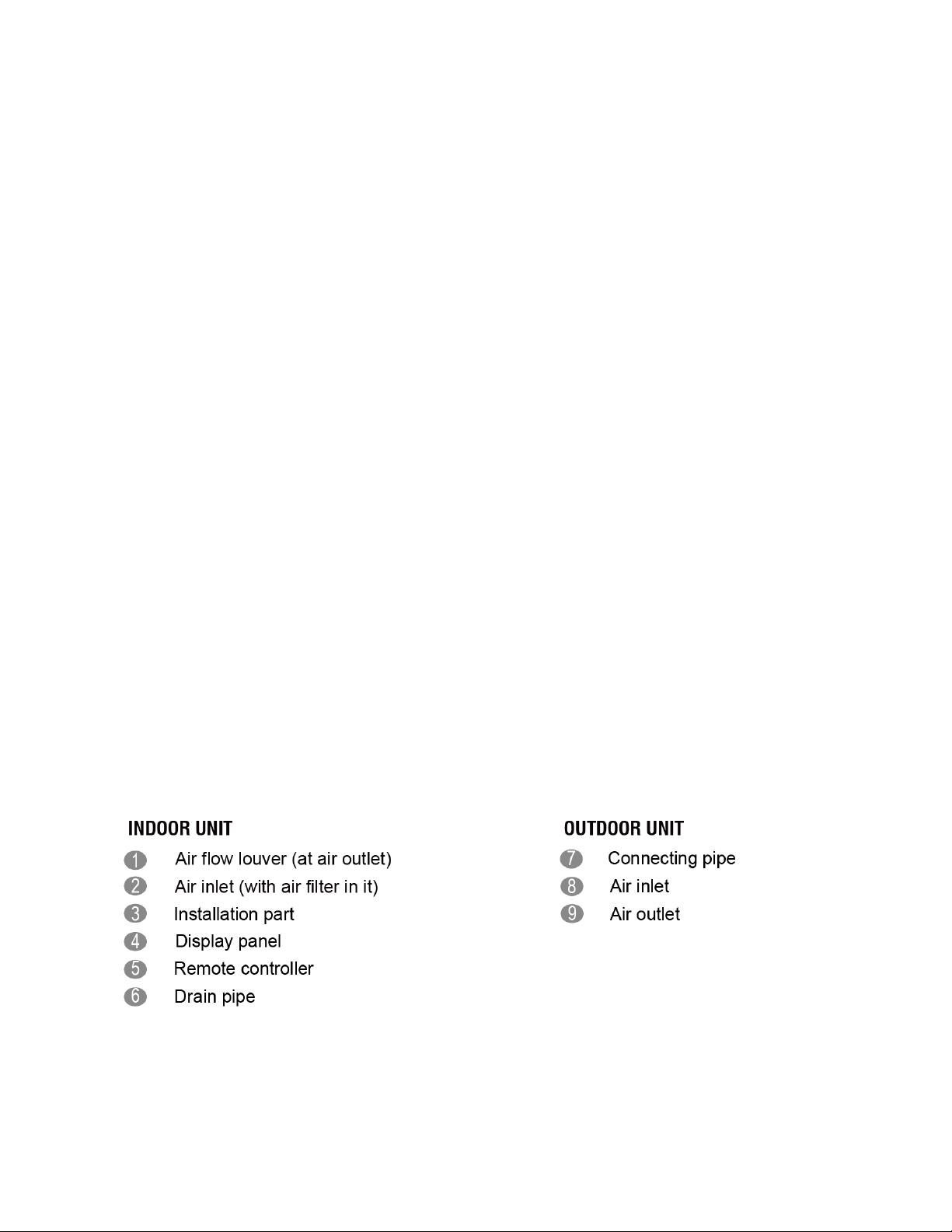
2. Part Names and Features
2.1 Model Names of Indoor / Outdoor Units
Series Capacity Indoor units
Cassette
KTIR09-H2
9K
Ducted
Cassette
KDIP09-H2
KTIR12-H2
12K
Ducted
Cassette
Floor Ceiling
Ducted
Ducted
Cassette
Floor Ceiling
Cassette
Ducted
18K
24K
36K
KDIP12-H2
KTIR18-H2
KUIR18-H2
KDIP18-H2
KDIP24-H2
KTIR24-H2
KUIR24-H2
KTIR036-H2G1
KDIR036-H2G1
Outdoor units
KSIE009-H221-O
KSIE012-H220-O
KSIE018-H220-O
KSIE024-H220-O
KSIR036-H218;
Floor Ceiling
Cassette
Ducted
48K
Floor Ceiling
Floor Ceiling 60K
KFUF036-H2G1
KTIR048-H2G1
KDIR048-H2G1
KFUF048-H2G1
KFUF060-H2G1 KSIR060-H218
KSIR048-H218;
4
a
s
o
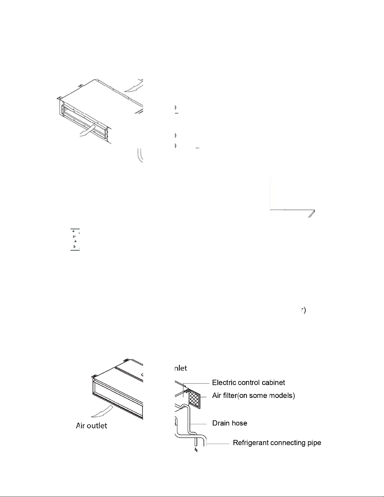
2.2 Part N
Cas
me of Ind
ette Units
or / Outdoor Unit
5
e
n
c
e
Ceiling R
cessed Du
ted Units
Ceili
g Recess
d Ducted Units
6

Console Units
7
Ceiling-floor Units
8

HESP DUCT Units
9
e
c
s
e
z
m
e
y
s
a
r
c
v
u
e
e
k
o
o
a
p
o
e
r
r
t
r
m
e
n
r
n
g
f
v
a
e
c
b
o
e
c
d
o
,
s
m
o
t
r
f
e
a
m
y
i
o
t
m
l
o
a
k
t
e
m
d
m
e
ttom
n
2.3 Featur
2.3.1 Du
2.3.1.1 Ea
Air inl
The si
botto
2.3.1.2 Fr
Install
Contin
health
s
ted Units
y Installati
t from rear
e of air inl
to rear sid
Air in
sh Air Inta
one duct fr
ually inhale
and comf
on: Two ai
is standard
t frame fro
, or from r
ake from re
e Functio
m the rese
the fresh ai
rtable.
Inlet Styl
for all capa
rear and
ar to the b
r (Standard)
ved fresh-a
r to improv
s (Bottom
ity; air inlet
ottom is sa
ttom, in ord
ir intake to
the quality
ide or Re
from botto
e, it’s ver
er to match
Air in
utdoor.
of the indo
r side)
easy to m
ng the inst
take from bo
is optiona
r air, fulfills
.
ve the cov
llation cond
(Optio
air quality
r from
ition.
al)
ore
2.3.1.3 Ea
Clean
It is e
side o
Repla
Remo
centrif
y Mainten
the filter (O
sy to draw
bottom sid
e the moto
e the ventil
gal fan. Di
nce
tional, sta
ut the filter
.
or centrifu
ated panel
ectly remo
dard produ
from the in
al fan
irstly. Rem
e two bolts
t without fil
oor unit fo
ve a half o
and then r
10
er)
cleaning, e
blower hou
place the
ven the filte
sing and ta
otor or cen
r is installe
e out the
trifugal fan
in rear
otor with
asily.
s
v
i
n
m
p
e
i
e
o
a
5
r
P
t
o
o
a
n
u
e
o
l
V
r
r
s
l
o
M
tor
B
ower Housing
2.3.1.4 Re
Reser
contro
2.3.1.5 Bu
Built-i
under
erved Re
ed remote
ller or a cen
lt-in Drain
drain pum
most space
ote On-off
on-off ports
tral controll
Rem
Pump (Opt
can lift th
condition.
and Centr
and central
r to realize
te on-off po
onal):
water to 7
l Control
control por
remote on-
ts Centr
0mm upm
orts
s, can con
ff control f
l control po
st. It’s conv
entilated Pane
ect the cab
nction or g
ts
nient to in
le of an on-
oup control
tall drainag
ff
function.
e piping
750mm upmost
11

i
a
n
i
d
W
a
o
c
e
e
l
b
a
h
d
e
d
c
o
y
.
c
n
n
o
y
2.3.1.6 Bu
The st
There
even i
The w
chips
lt-in Displ
ndard ind
is a display
the distan
red controll
etect som
ired Contro
y Board
or unit can
board with
e of 2m. T
r and the d
failure.
ler (Standar
e controlle
receiver in
e unit will r
isplay boar
)
d by wired
the E-box.
alized rem
can displa
ontroller.
Move out th
ter control
the error
Remote Co
e display, a
ode or prod
troller (Opti
d fix it in ot
uction code
nal)
her place,
when the
Displa
12
s
w
r
o
e
c
e
r
a
y
n
t
e
n
6
O
n
a
n
b
l
f
n
d
x
n
g
a
t
T
n
n
a
r
d
o
a
m
a
m
e
i
e
o
c
k
r
h
o
m
s
a
s
2.3.2 Ca
2.3.2.1
2.3.2.2
2.3.2.3
Lo
Optimi
Noise
Tu
Turbo
down
Fir
Electri
sette Uni
er Nois
ze air chan
max down
bo Mode (
function ca
r heat up r
-proof Co
al control
s
el system
dB.
ptional)
boost cool
pidly.
troller Bo
ox adopts
Cold
esign to e
Old
ing or heati
Comm
urbo Mo
ew design,
sure the m
g speed in
n vs. Turbo
e (After 3
which can
ximum qui
New
a short peri
Hot
0 min)
eet higher
tness and
od, and ma
fire safety
omfort.
es the roo
equirement
cool
.
New
2.3.2.4
2.3.2.5 Wi
Fr
sh Air
Fresh
Comp
misla
conve
air intake fu
ed Contro
ing. It's mai
red with in
ient.
nction brin
ler (Option
rared remo
ly used for
you fresh
l)
e controlle
commercia
nd comfort
, wired cont
l zone and
13
ble air feel
roller can b
akes air c
Old
ng.
fixed on t
nditioner c
e wall and
ntrol more
void

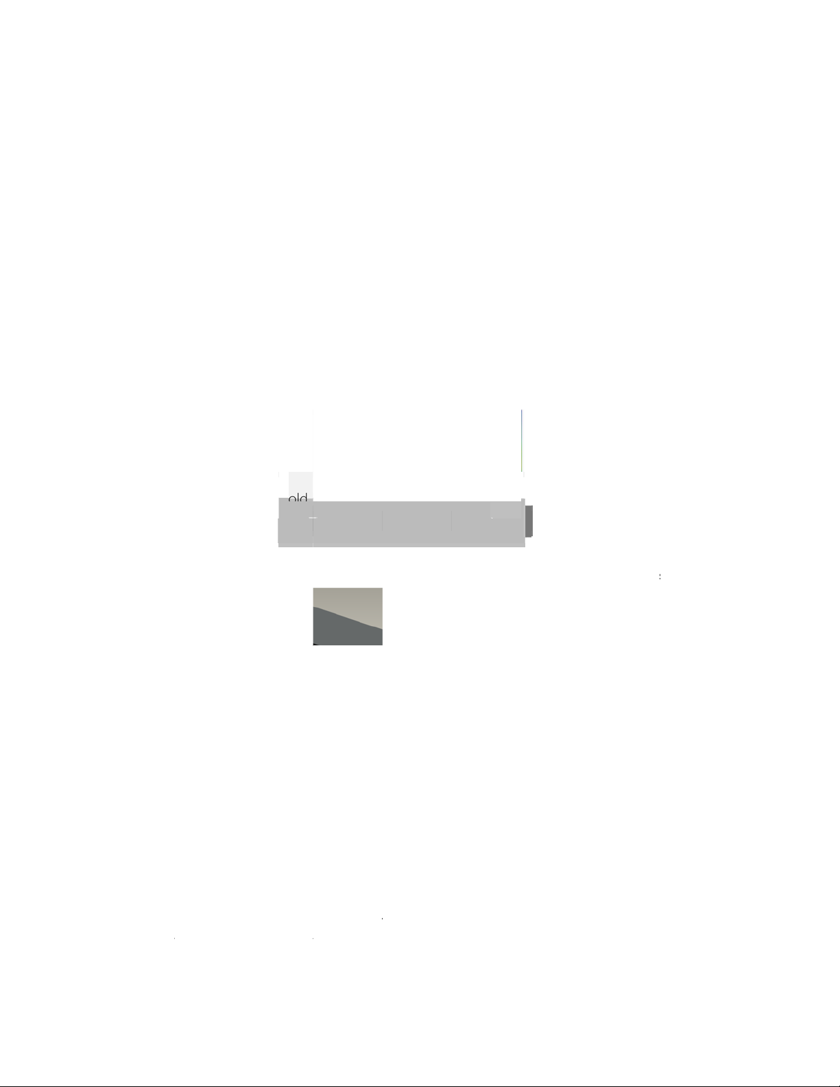
2.3.2.6 Build-in Drain Pump
The drain pump can lift the condensing water up to 750mm upmost.
It’s convenient to install drainage piping under most space condition.
2.3.2.7Terminals For Alarm Lamp and Long-distance On-off Controller Connection Are
Standard
Reserve terminals for the connection of alarm lamp and long-distance on-off controller, more
human control.
14

n
o
m
w
t
q
t
e
o
e
s
E
y
t
c
W
t
e
p
m
a
r
C
e
y
u
o
n
,
o
m
h
t
r
p
v
r
t
o
s
a
s
t
e
a
s
m
h
2.3.3 Co
2.3.3.1. M
The si
2.3.3.2. T
Cooling m
sole Unit
dern and
ple and st
o Air-outle
ode
legant Ap
lish design
Ways
earance
s can nicel
harmonies
with your li
ing space.
Air ou
room t
room
Air ou
has b
Heating m
Anti-c
in ord
lower l
Qui
let from top
emp. is still
uickly
let from top
en opened
ode
ld air ------
r to preven
ouver clos
k Cooling
and botto
high, cold
to maintain
over 1 hou
hen the A
cold air dir
d.
to make q
ir will be bl
room temp
, cold air on
is just tur
ct blowing
T
ick cooling
wn out fro
. ----When t
ly from the
on, tempe
only the u
15
maintain
------When
top and b
e room ha
op outlet to
ature of ev
per louver i
oom temp
he A/C is ju
ttom air ou
been cool
keep const
porator is v
opened in
st switched
let to cool d
d down, or
nt room te
ery low, in t
a high posi
on, or
own the
the A/C
p
is case,
tion, the

w
d
o
s
w
t
e
a
.
h
k
r
2.3.3.3. Fo
2.3.3.4. Lo
DC in
Low n
ur Air Inlet
Noise
oor fan mo
ise and en
or, which h
rgy saving
s five spee
ds.
Advan
ced centrifu
gal fan tec
nology ma
es a fast ai
flow and reduces the indoor noise.
16

l
w
o
a
a
r
s
D
y
m
p
n
o
t
t
s
g
g
n
s
y
o
p
e
r
d
M
c
s
e
n
e
l
o
d
r
o
i
d
o
m
o
a
h
e
e
e
a
k
c
h
n
e
e
a
n
e
p
a
t
e
d
e
t
p
c
h
i
l
f
t
r
c
r
f
2.3.4 Cei
2.3.4.1 T
The r
install
warm
2.3.4.2 B
Brief d
but al
2.3.4.3 3
Vertical air
airflow wa
whole roo
ing-floor
o-way In
unded desi
tion. Ceilin
ir.
ief Desig
esign that i
o upgrade
Airflow
flow and h
s help to s
can be ev
Units
tallation
n of the c
installatio
suitable fo
our lifestyl
rizontal airf
read air c
nly air-con
iling and fl
saves roo
r any interi
.
ow can be
mfortably t
itioned for
or type air
space, w
r will not o
djusted by
roughout
both floor-l
onditioner
ile floor ins
ly give you
remote con
ven a larg
vel and ceil
llows eith
allation hel
cooling and
troller, the
room. Wit
ing installat
r ceiling or
s prevent
heating pe
ooperation
these fun
on.
loor-level
he loss of
formance
of the two
tions, the
2.3.4.4 O
Both ri
pipe i
2.3.4.5 C
Remo
The fil
tional D
ght side an
stallation.
nvenien
e controller
er without
ainage Pi
left side d
ake you m
e Operat
as standar
crew fixed,
pe Conn
ainage hol
re conveni
ng and E
, wired con
can be too
ction
s are avail
nt during i
sy Maint
troller for o
out easily.
ble to avoi
stallation.
nance
tional.
the space
imitation fo
drainage
17

a
i
l
c
v
f
h
n
n
r
s
2.3.4.6 E
The pi
The w
sy Instal
pes can be
ring works
ation, Sa
connected
an be finis
e Worki
rom bottom
ed before i
g Time
, back and
stallation.
ight side, makes the in
tallation more easily.
18
c
g
i
d
o
d
p
c
u
e
a
a
i
o
n
e
K
v
s
p
I
a
r
n
t
l
n
a
e
s
6
o
K
r
a
o
m
o
u
t
m
t
u
R
h
t
d
r
o
y
a
d
s
a
e
u
e
h
c
2.3.5 Du
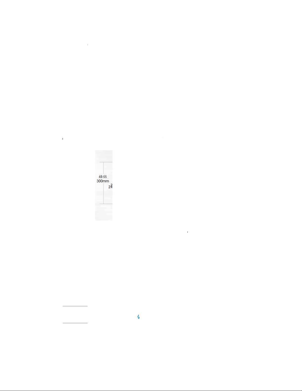
2.3.5.1.
2.3.5.2.
*18K unit -
Hi
As a d
The m
Sl
The in
ted Units
her Stat
ucted air c
aximum sta
m Desig
ustry Low
210mm,24
c Pressu
nditioner wi
tic pressure
st height is
/36K unit -
e
th medium
reaches 1
designed t
249mm,48
tatic press
0Pa
be fitted in
unit -300
re, it has t
o tight roof
m
e widest st
spaces.
tic pressur
range.
2.3.5.3. C
For or
an ex
With
press
2.3.5.4
Fl
The fr
applic
nstant air
inary duct,
erienced in
onstant air
re and kee
xible Air
me size of
tion.
olume co
when the s
taller to ca
volume co
constant
ntake Wa
ir inlet in r
trol
atic pressu
culate and
trol techn
ir volume.
y (Botto
ar and bott
e exceeds
djust the a
logy, the d
side or
m is the sa
he expecte
ir volume p
ct will aut
ear side)
me. It’s ver
range, it i
ecisely.
matically
easy to sw
fairly diffic
djusts to p
itch to matc
lt even for
rfect stati
different
19

o
c
a
s
n
h
e
y
i
w
a
k
o
o
Air int
a
u
o
r
(
r
S
o
m
e
o
h
e
o
a
o
b
m
u
y
m
ke from rear (
tandard)
Air int
ke from botto
(Optional)
2.3.5.5. C
A6 du
install
2.3.5.6
Ea
With a
excha
from t
mmunicat
t uses two
tion.
y Clean
larger wind
ger and w
e inside by
on wire co
ires witho
ow design,
ter receive
vacuum
nnection
t polarity c
nce the
tray in behi
nnection w
otor and th
nd can be s
ay, which al
e blower w
een very cl
most has n
eels have
arly. Dust c
mistake d
een detach
an be easil
ring the
ed, heat
removed
2.3.5.7 Fr
Install
Contin
health
sh air inta
one duct fr
ually inhale
and comf
e function
m the rese
the fresh ai
rtable.
Optional)
ved fresh-a
r to improv
ir intake to
the quality
20
utdoor.
of the indo
r air, fulfills
air quality
ore
e
a
n
m
O
p
b
r
e
l
p
v
5
s
6
o
s
m
i
h
S
a
r
a
n
A vent
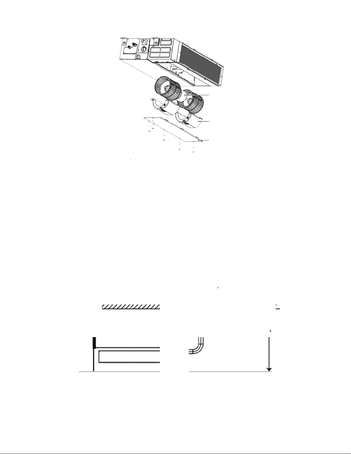
the fre
invert
ilation moto
sh air volu
r units, and
r (provided
e. There a
only option
y the insta
e reserved
al for DC in
ler) can be
orts for thi
erter 53~1
installed in
motor on
0 units).
ide the fres
ain PCB (
air duct to
tandard fo
improve
3D
2.3.5.8. Dr
Built-i
in pump (
drain pum
ptional)
can lift th
water to 7
0mm upm
st, which w
dens the dr
inage pipi
Max 750mm
g range.
21
S
g
t
a
s
n
r
e
x
e
L
U
e
r
n
e
a
p
g
n
a
i
p
d
g
a
P
d
m
y
a
e
o
s
s
s
e
s
f
a
s
p
2.3.6 HE
2.3.6.1 Hi
Max s
The lo
Speci
2.3.6.2 Ea
The u
P DUCT
h static pr
atic pressu
ngest dista
lly recomm
y mainten
it can be o
nits
ssure des
e of indoor
ce of air su
nded for s
nce
ened from
gn
unit is 200
pply is 40m
acious an
top or botto
a.
, the max h
large room
.
ight of air
s like large
upply is 6.5
tores and
m.
actories.
The ai
much
2.3.6.3 Fle
Differ
outlet flan
asier whe
ible Instal
nt solutions
-shaped are
e is isolate
connectin
lation
for any sh
from eithe
duct.
pe room b
r top panel
using kind
Are
s far apart
r base pan
of air distri
l, which m
bution duct
Y- s ha
kes the ma
.
ed area
intenance
22
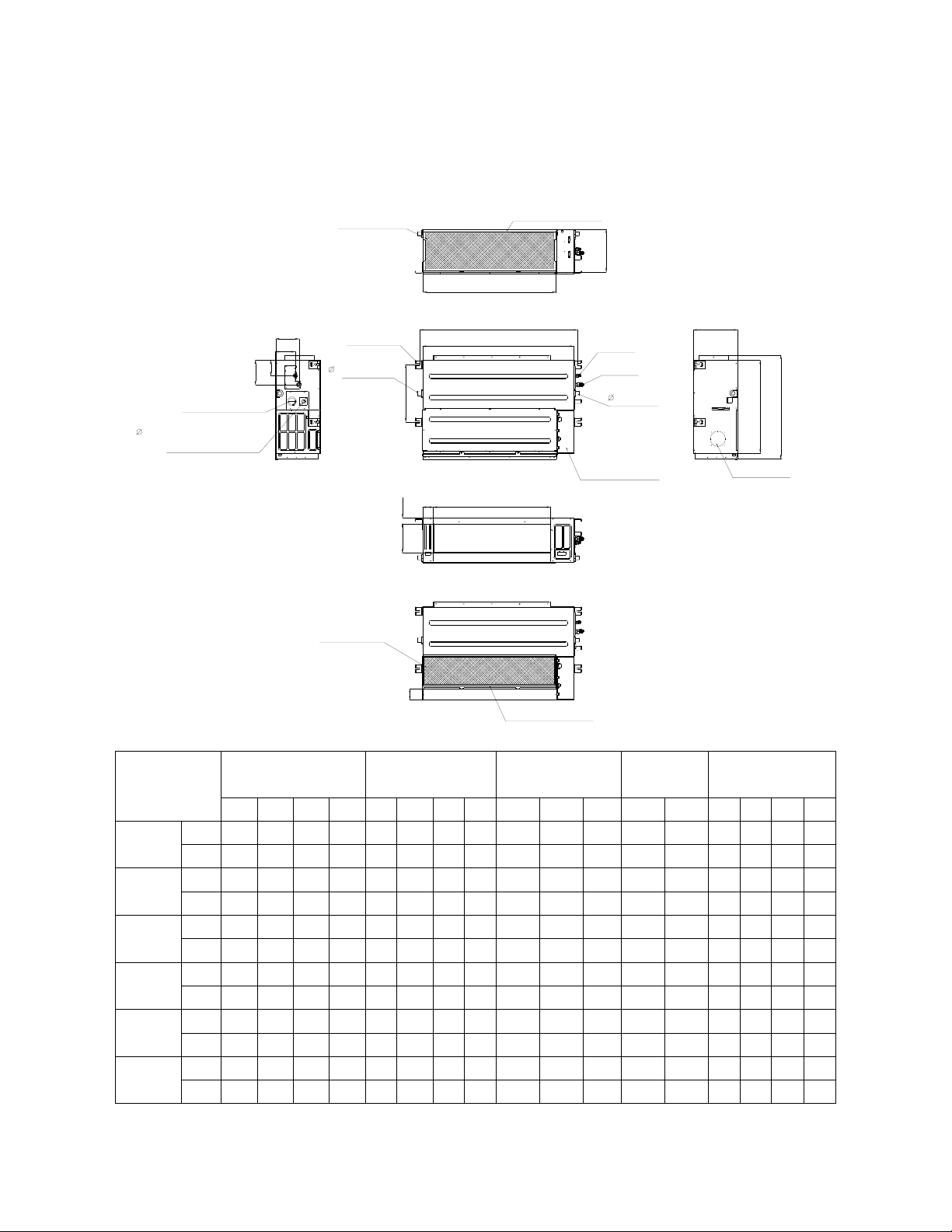
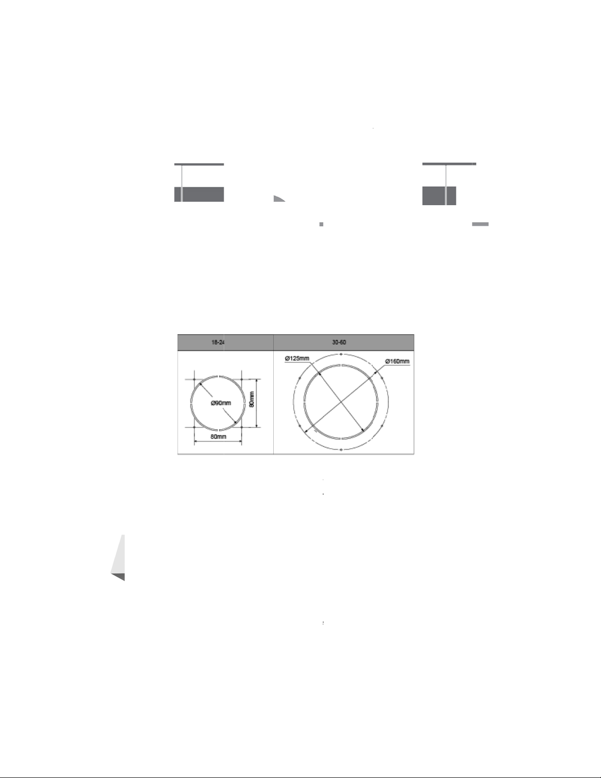
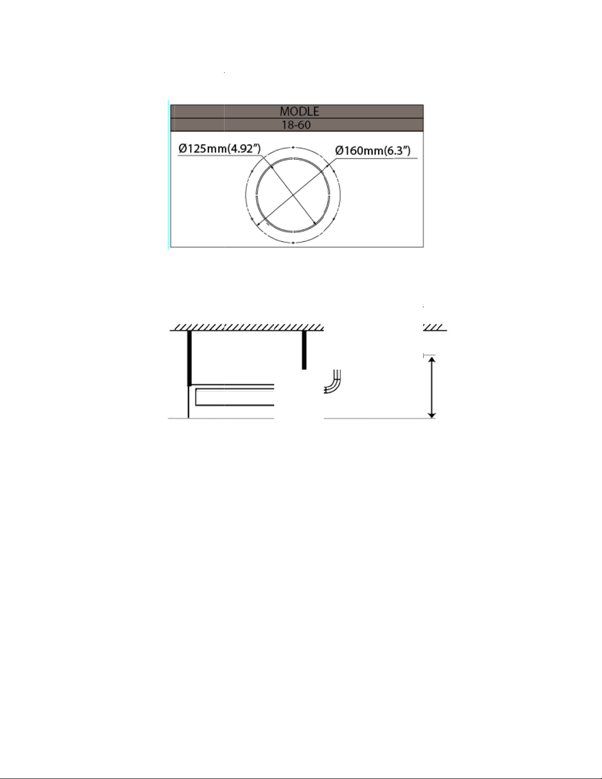
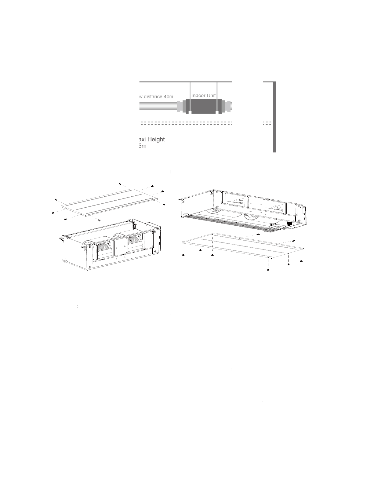
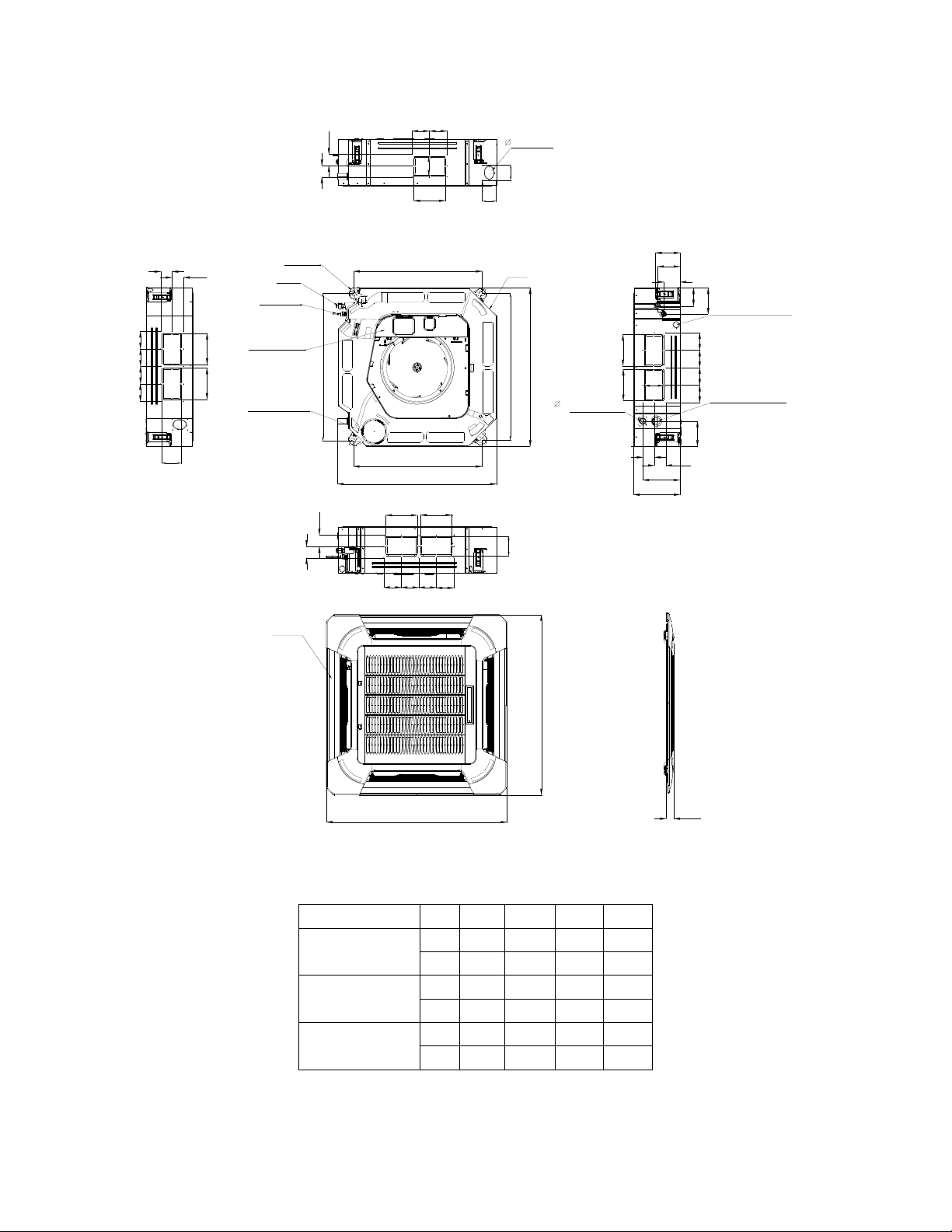
3. Dimensions
3.1 Indoor Unit
Ducted Units
Air filter ( optional )
air inlet from rear side
J
I
Test mouth & Test cover
25 Drain connecting pipe
( for pump )
Capacity (KBtu)
mm
9
12
18
24
36
48
in
mm
in
mm
in
mm
in
mm
in
mm
in
B
Fresh air intake
D
C
W2
H2
H1
W1
4-install hanger
25 Drain pipe
Air filter ( optional )
L
A
M
G
H
K
FE
air inlet from bottom side
Liquid side
Gas side
25 Drain pipe
Electric control box
Outline dimension(mm) Air outlet opening size Air return opening size
A B C D E F G H I J K L M H1 H2 W1 W2
700 210 635 570 65 493 35 119 595 200 80 740 350 120 143 95 150
27.56 8.27 25 22.44 2.56 19.41 1.38 4.69 23.43 7.87 3.15 29.13 13.78 4.72 5.63 3.74 5.91
700 210 635 570 65 493 35 119 595 200 80 740 350 120 143 95 150
27.56 8.27 25 22.44 2.56 19.41 1.38 4.69 23.43 7.87 3.15 29.13 13.78 4.72 5.63 3.74 5.91
920 210 635 570 65 713 35 119 815 200 80 960 350 120 143 95 150
36.22 8.27 25.00 22.44 2.56 28.07 1.38 4.69 32.09 7.87 3.15 37.80 13.78 4.72 5.63 3.74 5.91
920 270 635 570 65 713 35 179 815 260 20 960 350 120 143 95 150
36.22 10.63 25.00 22.44 2.56 28.07 1.38 7.05 32.09 10.24 0.78 37.80 13.78 4.72 5.63 3.74 5.91
1140 270 775 710 65 933 35 179 1035 260 20 1180 490 120 143 95 150
44.88 10.63 30.51 27.95 2.56 36.73 1.38 7.05 40.75 10.24 0.78 46.46 19.29 4.72 5.63 3.74 5.91
1200 300 865 800 80 968 40 204 1094 288 45 1240 500 175 198 155 210
47.24 11.81 34.06 31.50 3.15 38.11 1.57 8.03 43.07 11.34 1.77 48.82 19.69 6.89 7.80 6.10 8.27
Size of install
hanger
Size of refrigerant pipe
23
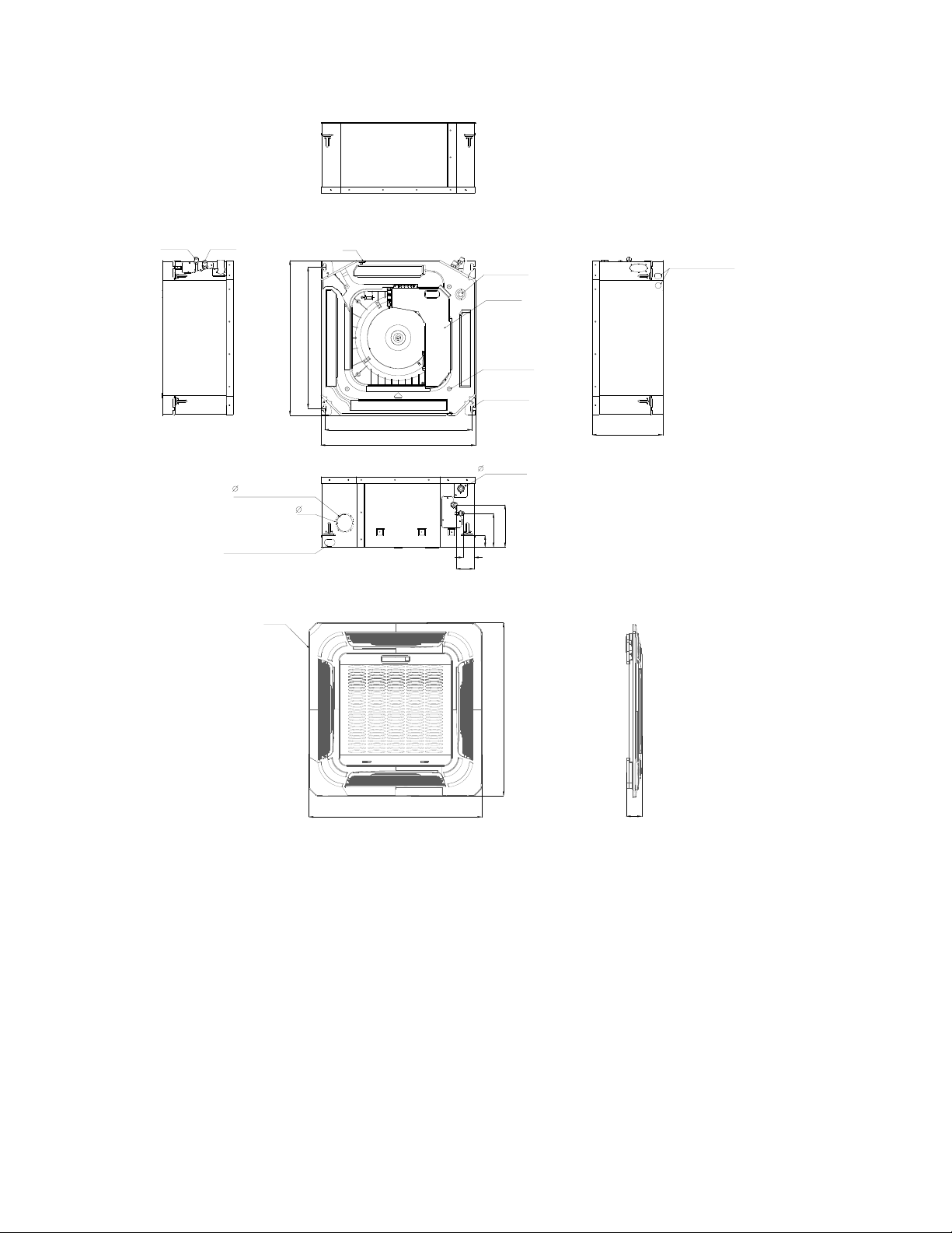
Cassette Units (9K, 12K, 18K)
Liquid side
Gas side
Fresh air intake
65
Wiring connection port
Panel
Body
523
570
545
570
75
( for Service )
E-parts box
4-Screw hole
(for install panel)
4-install hanger
44
42
68
Drain hole
Drain pipe25
157
126
Wiring connection port
260
647
647
50
24
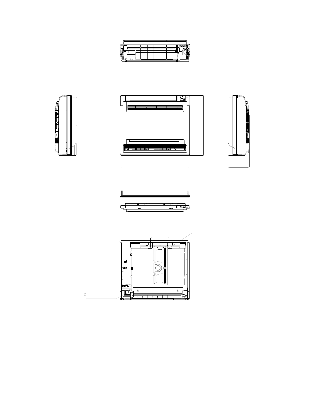
Cassette Units (24K, 36K, 48K)
D
D
D
D
92
9292
92
A
A
B
4-install hanger
Gas side
Liquid side
E-parts box
Service hole for
draining pump
780
D
D
92 92
75
Fresh air intake
B
A
680
680
840
A
A
80
80
136
Body
780
B
840
32
Drain hole
126
91
90
Wiring connection port
135
B
196
C
92929292
132
D
Test mouth &
Test cover
A
A
D
92 92
92
92
Panel
950
950
55
Capacity (Btu/h)
24K
36K
48K
A B C D
mm 160 75 205 50
inch 6.30 2.95 8.07 1.97
mm 160 95 245 60
inch 6.30 3.74 9.65 2.36
mm 160 95 287 60
inch 6.30 3.74 11.30 2.36
25
Console Units
600
16 Drain pipe
700
210
Hanging arm
195
Unit: mm
26
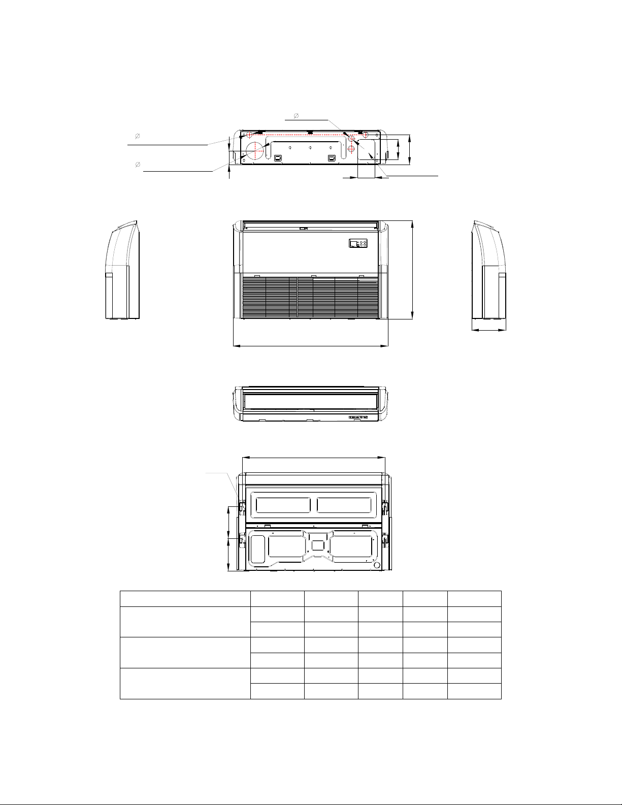
Ceiling-floor Units (18K-60K)
2
-
0
4
Drain discharge port
120
Fresh air intake
94
Wiring connection port
2
-
3
3
120
A
204
140
Refrigerant pipe hole
B
C
D
Hanging arm
220
222
Capacity (Btu/h)
18K / 24K
36K
48K/60K
A B C D
mm 1068 675 235 983
inch 42.05 26.57 9.25 38.70
mm 1285 675 235 1200
inch 50.59 26.57 9.25 47.24
mm 1650 675 235 1565
inch 64.96 26.57 9.25 61.61
27
 Loading...