

Page 1
K
SERVICE MANUAL
IV S
S
ERIES
Page 2

Table of Contents
§. Safety Precautions
1. Precautions
2. Information servicing(For flammable materials)
§. Specifications
1. Model Reference
2. Pipe length and the Drop Height
3. Electrical Wiring Diagrams
§. Product Features
1. Display Function
2. Safety Features
3. Basic Features
4. Optional Features
§. Maintenance
1. First Time Installation Check
2. Refrigerant Recharge
3. Re-Installation
§. Indoor Unit Disassembly
1. Dimension
2. Indoor Unit Disassembly
§. Outdoor Unit Disassembly
1. Outdoor Unit Table
2. Dimension
3.
Outdoor Unit Disassembly
Page 3

Table of Contents
§. Troubleshooting
1. Safety Caution
2. General Troubleshooting
3. Complain Record Form
4. Information Inquiry
5. Error Diagnosis and Troubleshooting Without Error Code
6. Quick Maintenance by Error Code
7. Troubleshooting by Error Code
8. Check Procedures
Appendix
i) Temperature Sensor Resistance Value Table for T1,T2,T3 and T4 (°C – K)
ii) Temperature Sensor Resistance Value Table for TP(for some units) (°C – K)
iii) Pressure On Service Port
Page 4

Safety Precautions
Contents
1. Precautions .............................................................................................................2
2. Information servicing(For flammable materials) .................................................3
Page 5

1. Precautions
To prevent personal injury, or property or unit damage,
adhere to all precautionary measures and instructions
outlined in this manual. Before servicing a unit, refer to this
service manual and its relevant sections.
Failure to adhere to all precautionary measures listed in this
section may result in personal injury, damage to the unit or
to property, or in extreme cases, death.
WARNING indicates a potentially hazardous
situation which if not avoided could result in serious
personal injury, or death.
CAUTION indicates a potentially hazardous situation
which if not avoided could result in minor or
moderate personal injury, or unit damage.
1.1 In case of Accidents or Emergency
WARNING
•• If a gas leak is suspected, immediately turn off the
gas and ventilate the area if a gas leak is suspected
before turning the unit on.
•• If strange sounds or smoke is detected from the unit,
turn the breaker off and disconnect the power supply
cable.
•• If the unit comes into contact with liquid, contact an
authorized service center.
•• If liquid from the batteries makes contact with skin or
clothing, immediately rinse or wash the area well with
clean water.
•• Do not insert hands or other objects into the air inlet
or outlet while the unit is plugged in.
•• Do not operate the unit with wet hands.
•• Do not use a remote controller that has previously
been exposed to battery damage or battery leakage.
CAUTION
•• Clean and ventilate the unit at regular intervals when
operating it near a stove or near similar devices.
•• Do not use the unit during severe weather conditions.
If possible, remove the product from the window
before such occurrences.
1.2 Pre-Installation and Installation
WARNING
•• Use this unit only on a dedicated circuit.
•• Damage to the installation area could cause the unit
to fall, potentially resulting in personal injury, property damage, or product failure.
•• Only qualified personnel should disassemble, install,
remove, or repair the unit.
•• Only a qualified electrician should perform electri-
cal work. For more information, contact your dealer,
seller, or an authorized service center.
CAUTION
•• While unpacking be careful of sharp edges around
the unit as well as the edges of the fins on the condenser and evaporator.
1.3 Operation and Maintenance
WARNING
•• Do not use defective or under-rated circuit breakers.
•• Ensure the unit is properly grounded and that a
dedicated circuit and breaker are installed.
•• Do not modify or extend the power cable. Ensure
the power cable is secure and not damaged during
operation.
•• Do not unplug the power supply plug during
operation.
•• Do not store or use flammable materials near the
unit.
•• Do not open the inlet grill of the unit during
operation.
•• Do not touch the electrostatic filter if the unit is
equipped with one.
•• Do not block the inlet or outlet of air flow to the unit.
•• Do not use harsh detergents, solvents, or similar items
to clean the unit. Use a soft cloth for cleaning.
•• Do not touch the metal parts of the unit when
removing the air filter as they are very sharp.
•• Do not step on or place anything on the unit or
outdoor units.
•• Do not drink water drained from the unit
•• Avoid direct skin contact with water drained from the
unit.
•• Use a firm stool or step ladder according to
manufacturer procedures when cleaning or
maintaining the unit.
CAUTION
•• Do not install or operate the unit for an extended
period of time in areas of high humidity or in an
environment directly exposing it to sea wind or salt
spray.
•• Do not install the unit on a defective or damaged
installation stand, or in an unsecure location.
•• Ensure the unit is installed at a level position
•• Do not install the unit where noise or air discharge
created by the outdoor unit will negatively impact the
environment or nearby residences.
•• Do not expose skin directly to the air discharged by
the unit for prolonged periods of time.
•• Ensure the unit operates in areas water or other
liquids.
•• Ensure the drain hose is installed correctly to ensure
proper water drainage.
•• When lifting or transporting the unit, it is
recommended that two or more people are used for
this task.
•• When the unit is not to be used for an extended time,
disconnect the power supply or turn off the breaker.
Safety Precautions 2
Page 6

2. Information servicing(For
flammable materials)
2.1 Checks to the area
• Prior to beginning work on systems containing flammable
refrigerants, safety checks are necessary to ensure that the
risk of ignition is minimized.
• For repair to the refrigerating system, the following
precautions shall be complied with prior to conducting work
on the system.
2.2 Work procedure
• Work shall be undertaken under a controlled procedure so
as to minimise the risk of a flammable gas or vapour being
present while the work is being performed.
2.3 Work procedure
• All maintenance staff and others working in the local area
shall be instructed on the nature of work being carried out.
• Work in confined spaces shall be avoided.
• The area around the work space shall be sectioned off.
Ensure that the conditions within the area have been made
safe by control of flammable material.
2.4 Checking for presence of refrigerant
• The area shall be checked with an appropriate refrigerant
detector prior to and during work, to ensure the technician
is aware of potentially flammable atmospheres.
• Ensure that the leak detection equipment being used is
suitable for use with flammable refrigerants, i.e. no sparking,
adequately sealed or intrinsically safe.
2.5 Presence of fire extinguisher
• If any hot work is to be conducted on the refrigeration
equipment or any associated parts, appropriate fire
extinguishing equipment shall be available to hand.
• Have a dry powder or CO2 fire extinguisher adjacent to the
charging area.
• Prior to work taking place, the area around the equipment
is to be surveyed to make sure that there are no flammable
hazards or ignition risks.
• NO SMOKING signs shall be displayed.
2.7 Ventilated area
• Ensure that the area is in the open or that it is adequately
ventilated before breaking into the system or conducting any
hot work. A degree of ventilation shall continue during the
period that the work is carried out. The ventilation should
safely disperse any released refrigerant and preferably expel
it externally into the atmosphere.
2.8 Checks to the refrigeration equipment
• Where electrical components are being changed,
they shall be fit for the purpose and to the correct
specification. At all times the manufacturer’s
maintenance and service guidelines shall be followed.
If in doubt consult the manufacturer’s technical
department for assistance. The following checks
shall be applied to installations using flammable
refrigerants:
• the charge size is in accordance with the room size
within which the refrigerant containing parts are
installed;
• the ventilation machinery and outlets are operating
adequately and are not obstructed;
• if an indirect refrigerating circuit is being used, the
secondary circuit shall be checked for the presence
of refrigerant; marking to the equipment continues
to be visible and legible.
• markings and signs that are illegible shall be
corrected;
• refrigeration pipe or components are installed in
a position where they are unlikely to be exposed
to any substance which may corrode refrigerant
containing components, unless the components
are constructed of materials which are inherently
resistant to being corroded or are suitably protected
against being so corroded.
2.6 No ignition sources
• No person carrying out work in relation to a refrigeration
system which involves exposing any pipe work that contains
or has contained flammable refrigerant shall use any sources
of ignition in such a manner that it may lead to the risk of
fire or explosion.
• All possible ignition sources, including cigarette smoking,
should be kept sufficiently far away from the site of
installation, repairing, removing and disposal, during which
flammable refrigerant can possibly be released to the
surrounding space.
Safety Precautions 3
2.9 Checks to electrical devices
• Repair and maintenance to electrical components shall
include initial safety checks and component inspection
procedures. If a fault exists that could compromise
safety, then no electrical supply shall be connected to
the circuit until it is satisfactorily dealt with. If the fault
cannot be corrected immediately but it is necessary to
continue operation, an adequate temporary solution
shall be used. This shall be reported to the owner of
the equipment so all parties are advised. Initial safety
checks shall include:
Page 7

• that capacitors are discharged: this shall be done in
a safe manner to avoid possibility of sparking;
• that there no live electrical components and wiring
are exposed while charging, recovering or purging
the system;
• that there is continuity of earth bonding.
2.10 Repairs to sealed components
• During repairs to sealed components, all electrical
supplies shall be disconnected from the equipment
being worked upon prior to any removal of sealed
covers, etc. If it is absolutely necessary to have an
electrical supply to equipment during servicing, then
a permanently operating form of leak detection shall
be located at the most critical point to warn of a
potentially hazardous situation.
• Particular attention shall be paid to the following to
ensure that by working on electrical components, the
casing is not altered in such a way that the level of
protection is affected. This shall include damage to
cables, excessive number of connections, terminals
not made to original specification, damage to seals,
incorrect fitting of glands, etc.
• Ensure that apparatus is mounted securely.
• Ensure that seals or sealing materials have not
degraded such that they no longer serve the
purpose of preventing the ingress of flammable
atmospheres. Replacement parts shall be in
accordance with the manufacturer’s specifications.
NOTE: The use of silicon sealant may inhibit the
effectiveness of some types of leak detection equipment.
Intrinsically safe components do not have to be isolated
prior to working on them.
2.11 Repair to intrinsically safe components
• Do not apply any permanent inductive or capacitance
loads to the circuit without ensuring that this will not
exceed the permissible voltage and current permitted
for the equipment in use. Intrinsically safe components
are the only types that can be worked on while live
in the presence of a flammable atmosphere. The test
apparatus shall be at the correct rating.
• Replace components only with parts specified by the
manufacturer. Other parts may result in the ignition of
refrigerant in the atmosphere from a leak.
2.12 Cabling
• Check that cabling will not be subject to wear,
corrosion, excessive pressure, vibration, sharp edges
or any other adverse environmental effects. The check
shall also take into account the effects of aging or
continual vibration from sources such as compressors
or fans.
2.13 Detection of flammable refrigerants
• Under no circumstances shall potential sources of
ignition be used in the searching for or detection of
refrigerant leaks. A halide torch (or any other detector
using a naked flame) shall not be used.
2.14 Leak detection methods
• The following leak detection methods are deemed
acceptable for systems containing flammable
refrigerants. Electronic leak detectors shall be used
to detect flammable refrigerants, but the sensitivity
may not be adequate, or may need re-calibration.
(Detection equipment shall be calibrated in a
refrigerant-free area.) Ensure that the detector is not
a potential source of ignition and is suitable for the
refrigerant used. Leak detection equipment shall be
set at a percentage of the LFL of the refrigerant and
shall be calibrated to the refrigerant employed and
the appropriate percentage of gas (25 % maximum)
is confirmed. Leak detection fluids are suitable for
use with most refrigerants but the use of detergents
containing chlorine shall be avoided as the chlorine
may react with the refrigerant and corrode the copper
pipe-work.
• If a leak is suspected, all naked flames shall be
removed or extinguished.
• If a leakage of refrigerant is found which requires
brazing, all of the refrigerant shall be recovered
from the system, or isolated (by means of shut off
valves) in a part of the systemremote from the leak.
Oxygen free nitrogen (OFN) shall then be purged
through the system both before and during the
brazing process.
2.15 Removal and evacuation
• When breaking into the refrigerant circuit to make
repairs or for any other purpose, conventional
procedures shall be used. However, it is important
that best practice is followed since flammability is a
consideration.
• The following procedure shall be adhered to:
• remove refrigerant;
• purge the circuit with inert gas;
• evacuate;
• purge again with inert gas;
• open the circuit by cutting or brazing.
Safety Precautions 4
Page 8

• The refrigerant charge shall be recovered into the
correct recovery cylinders. The system shall be flushed
with OFN to render the unit safe. This process may
need to be repeated several times. Compressed air or
oxygen shall not be used for this task. Flushing shall
be achieved by breaking the vacuum in the system
with OFN and continuing to fill until the working
pressure is achieved, then venting to atmosphere, and
finally pulling down to a vacuum. This process shall
be repeated until no refrigerant is within the system.
When the final OFN charge is used, the system shall
be vented down to atmospheric pressure to enable
work to take place. This operation is absolutely vital if
brazing operations on the pipe-work are to take place.
• Ensure that the outlet for the vacuum pump is not
close to any ignition sources and there is ventilation
available.
2.16 Charging procedures
• In addition to conventional charging procedures, the
following requirements shall be followed:
• Ensure that contamination of different refrigerants
does not occur when using charging equipment.
Hoses or lines shall be as short as possible to
minimize the amount of refrigerant contained in
them.
• Cylinders shall be kept upright.
• Ensure that the refrigeration system is earthed prior
to charging the system with refrigerant.
• Label the system when charging is complete (if not
already).
• Extreme care shall be taken not to overfill the
refrigeration system.
• Prior to recharging the system it shall be pressure
tested with OFN. The system shall be leak tested on
completion of charging but prior to commissioning.
A follow up leak test shall be carried out prior to
leaving the site.
2.17 Decommissioning
Before carrying out this procedure, it is essential that the
technician is completely familiar with the equipment and
all its detail. It is recommended good practice that all
refrigerants are recovered safely. Prior to the task being
carried out, an oil and refrigerant sample shall be taken.
In case analysis is required prior to re-use of reclaimed
refrigerant. It is essential that electrical power is available
before the task is commenced.
• Become familiar with the equipment and its operation.
• Isolate system electrically.
• Before attempting the procedure ensure that:
• mechanical handling equipment is available, if
required, for handling refrigerant cylinders;
• all personal protective equipment is available and
being used correctly;
• the recovery process is supervised at all times by a
competent person;
• recovery equipment and cylinders conform to the
appropriate standards.
• Pump down refrigerant system, if possible.
• If a vacuum is not possible, make a manifold so that
refrigerant can be removed from various parts of the
system.
• Make sure that cylinder is situated on the scales before
recovery takes place.
• Start the recovery machine and operate in accordance
with manufacturer’s instructions.
• Do not overfill cylinders. (No more than 80 % volume
liquid charge).
• Do not exceed the maximum working pressure of the
cylinder, even temporarily.
• When the cylinders have been filled correctly and the
process completed, make sure that the cylinders and
the equipment are removed from site promptly and all
isolation valves on the equipment are closed off.
• Recovered refrigerant shall not be charged into
another refrigeration system unless it has been cleaned
and checked.
2.18 Labelling
• Equipment shall be labelled stating that it has been decommissioned and emptied of
• refrigerant. The label shall be dated and signed. Ensure
that there are labels on the equipment stating the
equipment contains flammable refrigerant.
2.19 Recovery
• When removing refrigerant from a system, either for
servicing or decommissioning, it is recommended good
practice that all refrigerants are removed safely.
• When transferring refrigerant into cylinders, ensure
that only appropriate refrigerant recovery cylinders
are employed. Ensure that the correct numbers of
cylinders for holding the total system charge are
available. All cylinders to be used are designated
for the recovered refrigerant and labelled for that
refrigerant (i.e. special cylinders for the recovery of
refrigerant). Cylinders shall be complete with pressure
relief valve and associated shut-off valves in good
working order.
Safety Precautions 5
Page 9

• Empty recovery cylinders are evacuated and, if
possible, cooled before recovery occurs.
• The recovery equipment shall be in good working
order with a set of instructions concerning the
equipment that is at hand and shall be suitable for the
recovery of flammable refrigerants. In addition, a set
of calibrated weighing scales shall be available and in
good working order.
• Hoses shall be complete with leak-free disconnect
couplings and in good condition. Before using the
recovery machine, check that it is in satisfactory
working order, has been properly maintained and that
any associated electrical components are sealed to
prevent ignition in the event of a refrigerant release.
Consult manufacturer if in doubt.
• The recovered refrigerant shall be returned to the
refrigerant supplier in the correct recovery cylinder,
and the relevant Waste Transfer Note arranged. Do not
mix refrigerants in recovery units and especially not in
cylinders.
• If compressors or compressor oils are to be removed,
ensure that they have been evacuated to an
acceptable level to make certain that flammable
refrigerant does not remain within the lubricant.
The evacuation process shall be carried out prior to
returning the compressor to the suppliers. Only electric
heating to the compressor body shall be employed
to accelerate this process. When oil is drained from a
system, it shall be carried out safely.
Safety Precautions 6
Page 10

Specifications
Contents
1. Model Reference ....................................................................................................2
2. Pipe Length and Drop Height ...............................................................................3
3. Electrical Wiring Diagrams ....................................................................................4
Page 11

1. Model Reference
Refer to the following table to determine the specifi c indoor and outdoor unit model.
Indoor Unit Model Outdoor Unit Model Capacity (Btu) Power Supply
KSIV009-H119-IW
KSIV009-H219-IW KSIV009-H219-O
KSIV012-H219-IW KSIV012-H219-O
KSIV012-H119-IW
KSIV018-H219-IW KSIV018-H219-O
KSIV024-H219-IW KSIV024-H219-O
KSIV009-H119-O
KSIV012-H119-O
9K
9K
12K
12K
18K
24K
115V~ , 60Hz,
1Phase
208/230V~, 60Hz,
1Phase
208/230V~, 60Hz,
1Phase
115V~ , 60Hz,
1Phase
208/230V~, 60Hz,
1Phase
208/230V~, 60Hz,
1Phase
Specifi cations 2
Page 12
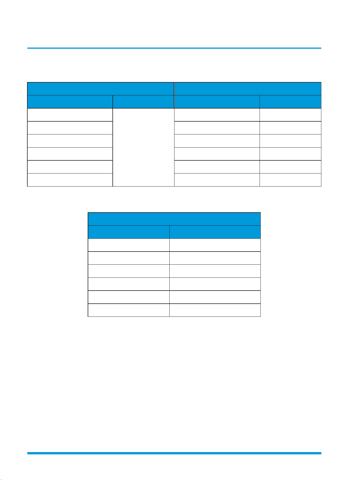
2. Pipe Length and Drop Height
The length and elevation of connection pipe are shown in the table below. if the pipe length exceeds max pipe length,
additional refrigerant should be charged to ensure nominal cooling/heating capacity.
Capacity(Btu) Standard Length Max Pipe Length Max Elevation Additional Refrigerant
9k
82ft 32.8ft
0.32oz/ft12K
24.6ft
18K 98.4ft
65.6ft
24K
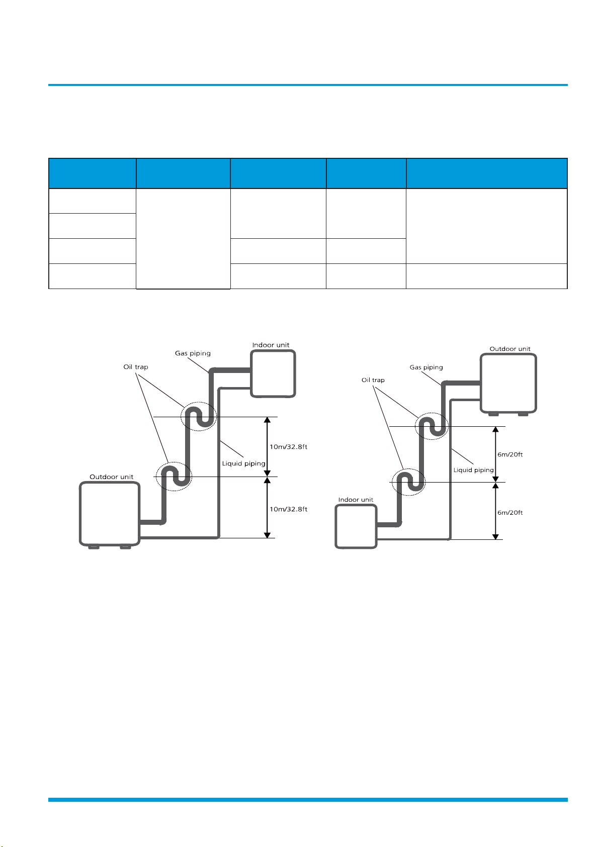
If oil fl ows back into the outdoor unit’s compressor, this might cause liquid compression or deterioration of oil return. Oil
traps in the rising gas pipe can prevent this.
1. Indoor unit is installed higher than outdoor unit 2. Outdoor unit is installed higher than indoor unit
164ft 82ft 0.64oz/ft
If indoor unit is installed higher than outdoor unit, oil trap should be set every 10m(32.8ft) of vertical distance.
If the outdoor unit is installed higher than the indoor unit, proper oil should return to the compressor along with the
suction of refrigerant to keep lubrication of compressor. If the suction fl ow velocity drops below 7.62m/s(1500fpm (feet
per minute)), oil won’t return to the compressor. An oil trap should be installed every 6m(20ft) of vertical distance.
Specifi cations 3
Page 13
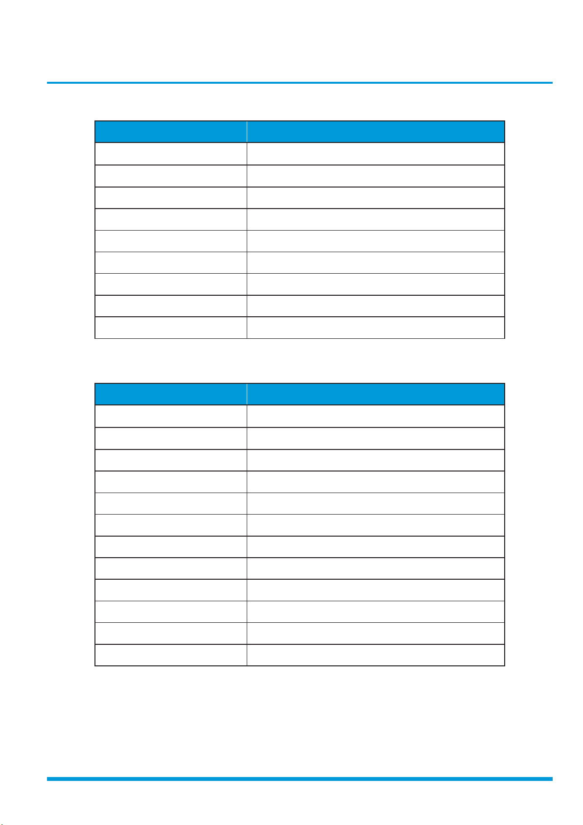
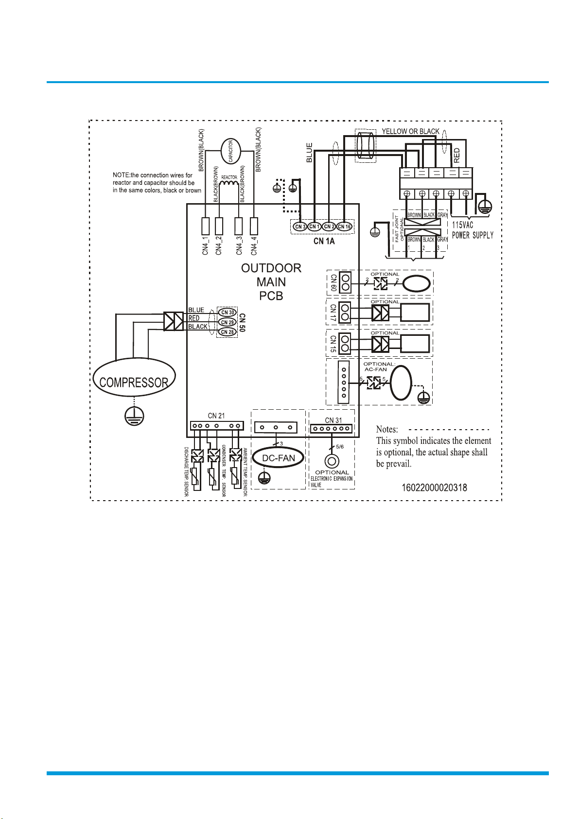
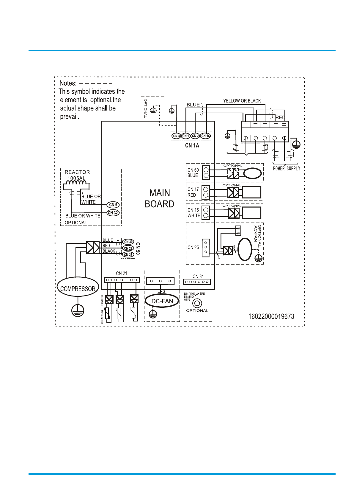
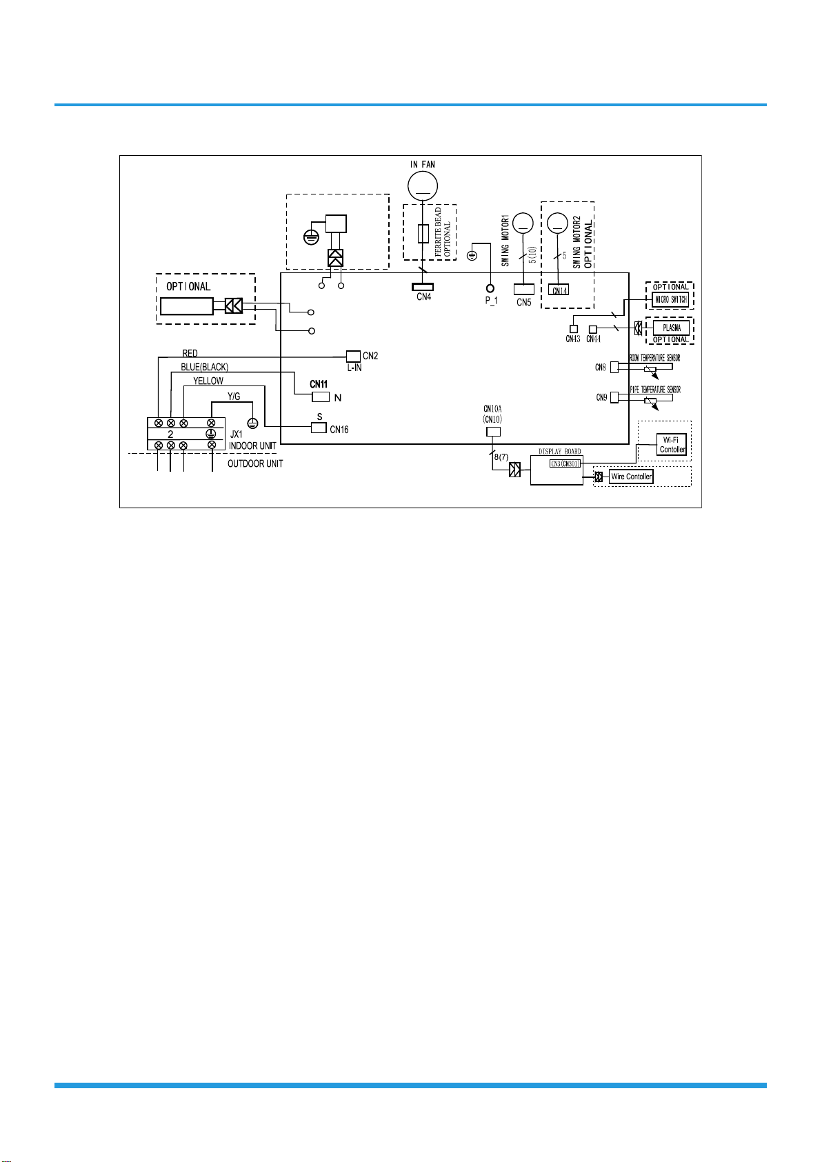
3. Electrical Wiring Diagrams
Indoor and outdoor unit wiring diagram
Indoor Unit Outdoor Unit
IDU Model IDU Wiring Diagram ODU Model ODU Wiring Diagram
KSIV009-H119-IW
KSIV009-H219-IW
KSIV012-H219-IW KSIV012-H219-O
16022000019694
KSIV012-H119-IW
KSIV018-H219-IW KSIV018-H219-O
KSIV024-H219-IW KSIV024-H219-O
Outdoor unit printed circuit board diagram
Outdoor Unit
ODU Model ODU Printed Circuit Board
KSIV009-H119-O
KSIV009-H219-O
KSIV012-H219-O
KSIV009-H119-O
KSIV009-H219-O
KSIV012-H119-O
17122000019195
17122000002718
17122000002718
16022000020318
16022000019673
16022000019673
16022000020318
16022000019673
16022000020500
KSIV012-H119-O
KSIV018-H219-O
KSIV024-H219-O
17122000019195
17122000002718
17122000041117
Specifi cations 4
Page 14
Indoor unit abbreviations
Abbreviation Paraphrase
Y/G Yellow-Green Conductor
Outdoor unit abbreviations
Abbreviation Paraphrase
ION
CAP Capacitor
PLASMA Electronic Dust Collector
L LIVE
N NEUTRAL
Heater The Electric Heating Belt of Indoor Unit
T1 Indoor Room Temperature
T2 Coil Temperature of Indoor Heat Exchanger
4-WAY Gas Valve Assembly/4-WAY VALVE
AN Alternating Current FAN
AC-F
Positive and Negative Ion Generator
DC-FAN Direct Current FAN
CT1 AC Current Detector
COMP Compressor
T3 Coil Temperature of Condenser
T4 Outdoor Ambient Temperature
TH Compressor Suction Temperature
TP Compressor Discharge Temperature
EEV Electronic Expansion Valve
L-PRO Low Pressure Switch
H-PRO High Pressure Switch
Specifi cations 5
Page 15
Outdoor unit wiring diagram: KSIV009-H119-O
Y/G
Y/G
E
U
N
W
O
R
B
2
1
3
BL
L
N
Y/G
Y/G
TO I NDOOR UNI T
4-WAY
BLUE
RED
BLACK
V
U
W
CRANKCASE
HEATER
PAN
HEATER
AC-FAN
CN 25
Y/G
Y/G
Y/G
CN 7
OPTIONAL:
DC-FAN
Page 16
Outdoor unit wiring diagram: KSIV009-H219-O / KSIV012-H219-O
U
BLUE
RED
Y/G
Y/G
BLUE OR BLACK
BROWN
2
1
3
L1
L2
Y/G
Y/G
INDOOR UNI T
4-WAY
CRANKCASE
HEATER
PAN
HEATER
CAPACITOR
AC-FAN
Y/G
BLACK
CN 7
V
W
CONDENSE R TE MP SENSOR.
AMBIENT TEMP. SENSOR
Y/G
OPTIONAL:
DC-FAN
Y/G
Page 17
16022000019694
KSIV009-H119-IW, KSIV009-H219-IW, KSIV012-H219-IW, KSIV012-H119-IW
KSIV018-H219-IW, KSIV024-H219-IW
Indoor
HEATER
OPTI ONAL
Y/ G
I ON
CN12_1
CN6_1
CN6_2
CN12_2
M
M
M
5
2
2
1
3
INDOOR WIRING DIAGRAM
OPTIONAL
OPTIONAL
Page 18

Outdoor unit printed circuit board diagram: KSIV009-H119-O
Page 19
No. Name CN# Meaning
CN3 Earth: connect to Ground
1 Power Supply
2 S CN16 S: connect to indoor unit communication
3 HEAT1 CN17 connect to compressor heater, 100-130V AC when is ON
4 4-WAY CN60 connect to 4 way valve, 100-130V AC when is ON.
5 AC-FAN CN25 connect to AC fan
6 TP T4 T3 CN21
7 HEAT2 CN15 connect to chassis heater, 100-130V AC when is ON
8 PMV CN31 connect to Electric Expansion Valve
9 DC-FAN CN7 connect to DC fan
10 FAN_IPM IPM 501 IPM for DC fan
11 TESTPORT CN6 used for testing
CN1 N_in: connect to N-line (100-130V AC input)
CN2 L_in: connect to L-line (100-130V AC input)
connect to pipe temp. sensor T3, ambient temp. sensor T4, exhaust
temp. sensor TP
12 EE_PORT CN505 EEPROM programer port
13 MCUPORT CN507 connect to PC communication
W CN28 connect to compressor
14
15 COMP_IPM IPM 301 IPM for compressor
16 BR1 BR1 Bridge
Note: This section is for reference only. Please take practicality as standard.
V CN29 0V AC (standby)
U CN30 10-230V AC (running)
Page 20

Outdoor unit printed circuit board diagram: KSIV009-H219-O
Page 21

No. Name CN# Meaning
CN3 Earth: connect to Ground
1 Power Supply
2 S CN16 S: connect to indoor unit communication
3 HEAT1 CN17 connect to compressor heater, 208-230V AC when is ON
4 4-WAY CN60 connect to 4 way valve, 208-230V AC when is ON.
5 HEAT2 CN15 connect to chassis heater, 208-230V AC when is ON
6 AC-FAN CN25 connect to AC fan
7 TP T4 T3 CN22
8 TP T4 T3 CN21
9 PMV CN31 connect to Electric Expansion Valve
10 DC-FAN CN7 connect to DC fan
CN1 N_in: connect to N-line (208-230V AC input)
CN2 L_in: connect to L-line (208-230V AC input)
connect to pipe temp. sensor T3, ambient temp. sensor T4, exhaust
temp. sensor TP
connect to pipe temp. sensor T3, ambient temp. sensor T4, exhaust
temp. sensor TP
11 FAN_IPM IPM 501 IPM for DC fan
12 TESTPORT CN6 used for testing
13 EE_PORT CN505 EEPROM programer port
14 MCUPORT CN507 connect to PC communication
W CN28 connect to compressor
15
16 COMP_IPM IPM 301 IPM for compressor
17 CN9 CN9 connect to reactor
18 CN32 CN32 connect to reactor
Note: This section is for reference only. Please take practicality as standard.
V CN29 0V AC (standby)
U CN30 10-200V AC (running)
Page 22

Product Featur
es
Contents
1. Display Function ....................................................................................................2
2 Safety Features ......................................................................................................3
3. Basic Functions .......................................................................................................4
3.1 Table .............................................................................................................4
3.2 Abbreviation ..................................................................................................5
3.3 Fan Mode ......................................................................................................5
3.4 Cooling Mode ...............................................................................................5
3.5 Heating Mode(Heat Pump Units) ...................................................................5
3.6 Auto-mode ....................................................................................................7
3.7 Drying Mode .................................................................................................7
3.8 Forced Operation Function ............................................................................7
3.9 Sleep Function ...............................................................................................7
3.10 Auto-Restart Function ....................................................................................7
3.11 Refrigerant Leakage Detection .......................................................................8
3.12 Ionizer/Plasma (for some models)
4. Optional Functions ................................................................................................9
...................................................................8
Page 23
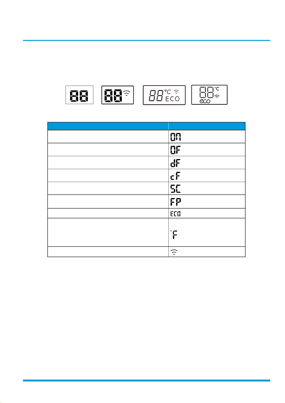
1. Display Function
Unit display functions
F
(B)
(C)
(3s)
(3s)
(A)
Function Display
Activation of Timer ON, Fresh, Swing, Turbo, or Silent
Cancellation of Timer OFF, Fresh, Swing, Turbo, or Silent
Defrost
Warming in heating mode
Self-clean (available on select units only)
Heating in room
tempurature under 47°
ECO function (available on select units only)
Lights up in different colour according to the operation
mode(some units):
Under COOL and DRY mode, it displays as cool colour.
Under HEAT mode, it displays as warm colour.
when Wireless Control feature is activated(some units)
(D)
Note: Please select the display function according to your purchase product.
Product Features 2
Page 24

2. Safety Features
Compressor three-minute delay at restart
Compressor functions are delayed for up to one minute upon the first startup of the unit, and are delayed for up to three
minutes upon subsequent unit restarts.
Zero crossing detection error protection(Except for DC fan units)
If AC can not detect zero crossing signal for 4 minutes or the zero crossing signal time interval is not correct, the unit will
stop and the LED will display the failure. The correct zero crossing signal time interval should be between 6-13ms.
Automatic shutoff based on discharge temperature
If the compressor discharge temperature exceeds a certain level for a period of time, the compressor ceases operation.
Automatic shutoff based on fan speed
If the indoor fan speed registers below 300RPM for an extended period of time, the unit ceases operation and the
corresponding error code is displayed on the indoor unit.
Inverter module protection
The inverter module has an automatic shutoff mechanism based on the unit’s current, voltage, and temperature. If
automatic shutoff is initiated, the corresponding error code is displayed on the indoor unit and the unit ceases operation.
Indoor fan delayed operation
• When the unit starts, the louver is automatically activated and the indoor fan will operate after a period of 7
seconds.
• If the unit is in heating mode, the indoor fan is regulated by the anti-cold wind function.
Sensor redundancy and automatic shutoff
• If one temperature sensor malfunctions, the air conditioner continues operation and displays the corresponding
error code, allowing for emergency use.
• When more than one temperature sensor is malfunctioning, the air conditioner ceases operation.
Refrigerant leakage detection
This function is active only when cooling mode is selected. It will detect if the compressor is being damaged by
refrigerant leakage or by compressor overload. This is measured using the coil temperature of evaporator T2 when the
compressor is in operation.
Product Features 3
Page 25
3. Basic Functions
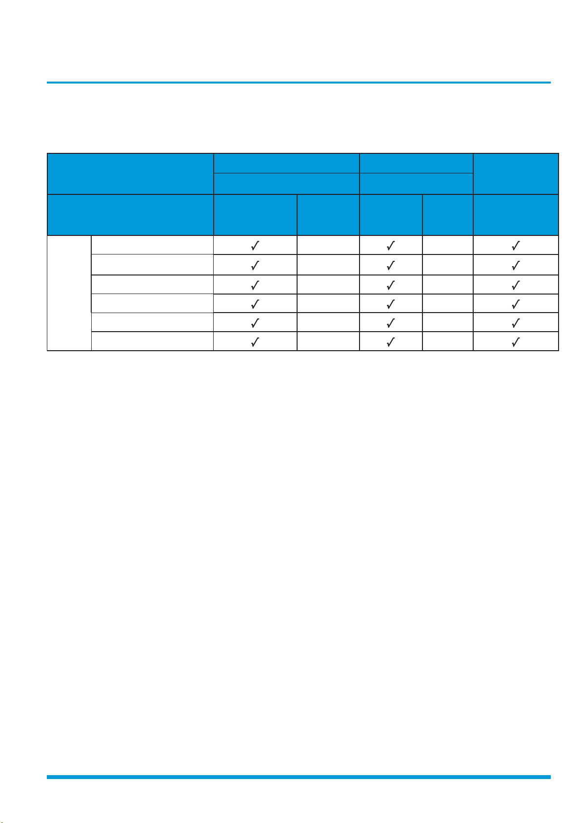
3.1 Table
Functions
Cooling Mode&Heating mode Heating Mode
Auto Mode
Outdoor Fan Control Defrosting Mode
Cases
Case 1:
Compressor
Frequency and T4
Case 2:T4
Case 1:T3
and T4,15
min
Case 2:
T3,10 min
A=2°C(3.6°F),
B=-2°C(-3.6°F)
KSIV009-H119-IW
KSIV009-H219-IW
KSIV012-H219-IW
Models
KSIV012-H119-IW
KSIV018-H219-O
KSIV024-H219-O
Note: The detailed description of case 1 or case 2 is shown in the following function sections(from 3.4 to 3.6).
Product Features 4
Page 26
3.2 Abbreviation
Setting fan
speed
Actual fan speed
H+(H+=H+G)
A H(=H)
B
C
M+(M+=M+Z)
D M(M=M)
E
F
L+(L+=L+D)
G L(L=L)
H
I
T1-Td ℃(°F)
L
L-(L-=L-D)
H
H-(H-=H-G)
M
M-(M-=M-Z)
a
b
c
d
T1-Td
e
Unit element abbreviations
Abbreviation Element
T1 Indoor room temperature
T2 Coil temperature of evaporator
T3 Coil temperature of condenser
T4 Outdoor ambient temperature
TS Set temperature
Td Control target temperature
TP Compressor discharge temperature
auto.
• If the compressor ceases operation when the
configured temperature is reached, the indoor fan
motor operates at the minimum or configured speed.
• The indoor fan is controlled as below:
In this manual, such as TCE1, TCE2...etc., they are well-
setting parameter of EEPROM.
3.3 Fan Mode
When fan mode is activated:
• The outdoor fan and compressor are stopped.
• Temperature control is disabled and no temperature
setting is displayed.
• The indoor fan speed can be set to high, medium, low,
or auto.
•
The louver operations are identical to those in cooling
mode.
• Auto fan: In fan-only mode, AC operates the same as
auto fan in cooling mode with the temperature set at
75.2°F.
3.4 Cooling Mode
3.4.1 Compressor Control
Cooling temperature compensation(∆T5) is a well-setting
parameter of EEPROM. It’s value ranges from 28°F to 36°F.
The default value is 0.
• When T1-Ts < ∆T5-2℃(3.6°F), the compressor ceases
operation.
• When T1-Ts > ∆T5+3℃(5.4°F), the compressor
continues operation.
• When the AC is operating in mute mode, the
compressor operates at a low frequency.
• When the current exceeds the preset value, the current
protection function activates and the compressor
ceases operation.
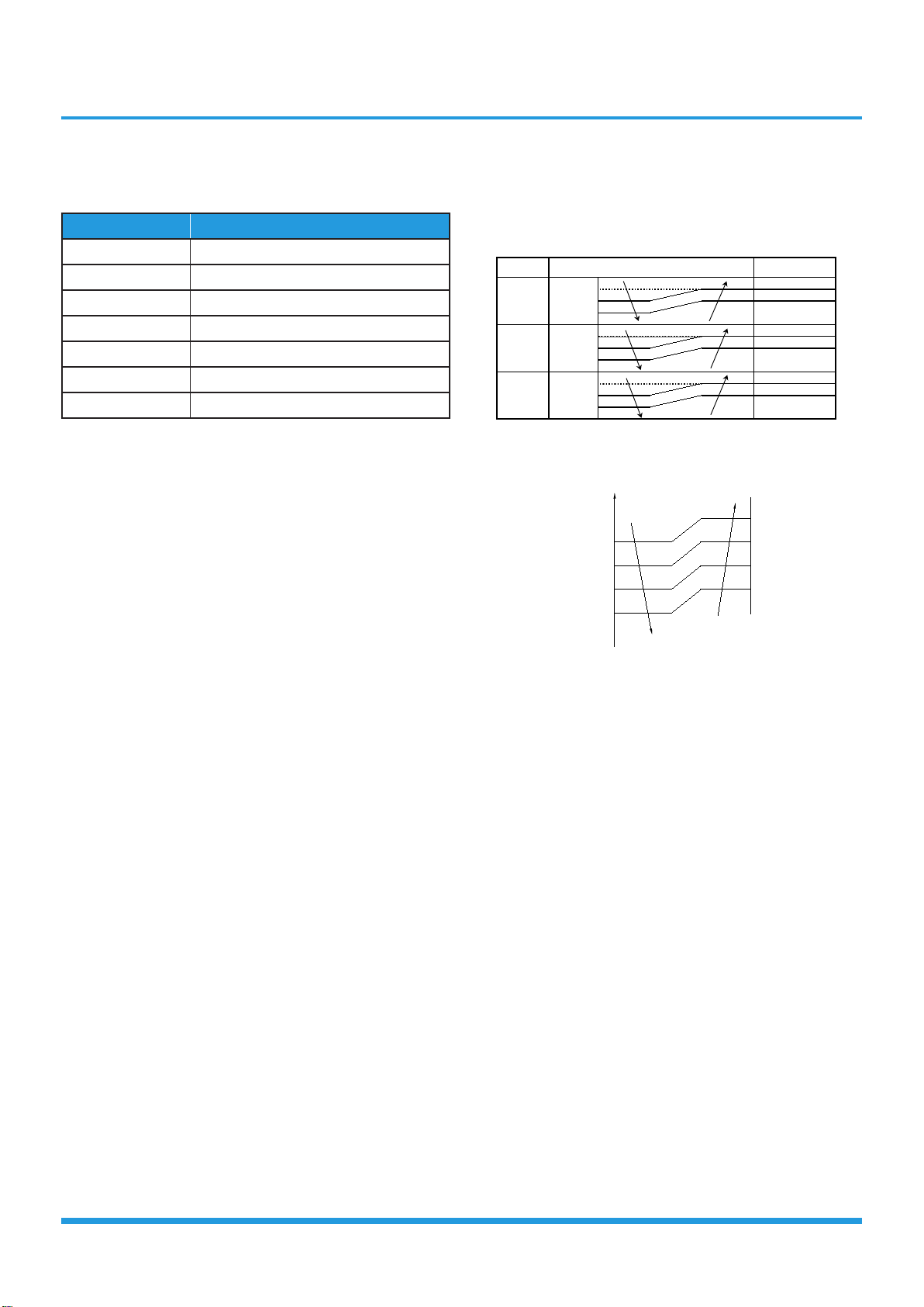
3.4.2 Indoor Fan Control
• In cooling mode, the indoor fan operates continuously.
The fan speed can be set to high, medium, low, or
Product Features 5
• The auto fan acts as below rules:
3.4.3 Outdoor Fan Control
Case 1:
• The outdoor unit will be run at different fan speed
according to T4 and compressor frequency.
• For different outdoor units, the fan speeds are
different.
Case 2:
• The outdoor unit will be run at different fan speed
according to T4.
• For different outdoor units, the fan speeds are
different.
3.4.4 Condenser Temperature Protection
When condenser temperature is more than setting value,
the compressor ceases operation..
3.4.5 Evaporator Temperature Protection
When evaporator temperature drops below a configured
value, the compressor and outdoor fan cease operation.
3.5 Heating Mode(Heat pump units)
3.5.1 Compressor Control
Heating temperature compensation(∆T3) is a well-setting
Page 27
parameter of EEPROM. It’s value ranges from 21°F to 43°F.
T2
Setting fan speed
H
M+
M
L
Super slow
Fan off
TEL0+23-
TE1
TEL0+21- TE1
TEL0+19- TE1
TEL0+17- TE1
TEL0+15- TE1
TEL0+13- TE1
TEL0+18- TE1
TEL0+16- TE1
TEL0+14- TE1
TEL0+12- TE1
TEL0+10- TE1
TEL0
Setting fan
speed
A c tual fan speed
H(=H)
H+(H+=H+G)
M(M=M)
M+(M+=M+Z)
L(L=L)
L+(L+=L+D)
H-(H- =H-G)
M-(M-=M-Z)
L-(L-=L-D)
T1-Td℃(℉)
L
H
M
T1-Td
• When T1-Ts>-∆T3, the compressor ceases operation.
• When T1-Ts<-
∆T3 2.7°F, the compressor continues
operation.
• When the AC is operating in mute mode, the
compressor operates at a low frequency.
• When the current exceeds the preset value, the
current protection function activates and the
compressor ceases operation.
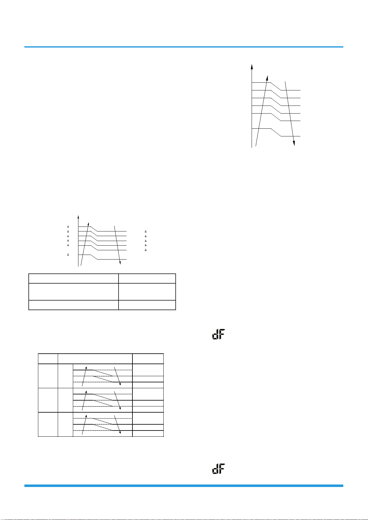
3.5.2 Indoor Fan Control:
• When the compressor is on, the indoor fan speed can
be set to high, medium, low, or auto. And the anticold wind function has the priority.
• Anti-cold air function
• The indoor fan is controlled by the indoor
temperature T1 and indoor unit coil temperature
T2.
3.5.3 Outdoor Fan Control:
Case 1:
• The outdoor unit will be run at different fan speed
according to T4 and compressor frequency.
• For different outdoor units, the fan speeds are
different.
Case 2:
• The outdoor unit will be run at different fan speed
according to T4.
• For different outdoor units, the fan speeds are
different.
T1 ≥ 66.2°F
59°F ≤ T1 ≤
64.4°F
ΔTE1=0
ΔTE1=34.2°F-T1
T1<59°F ΔTE1=7.2°F
• When the indoor temperature T1 reaches the setting
temperature, the compressor continues operation,
the indoor fan motor runs at the minimum speed or
setting speed.(The anti-cold air function is valid).
• The indoor fan is controlled as below:
• Auto fan action in heating mode:
Product Features 6
3.5.4 Defrosting mode
Case 1:
• The unit enters defrosting mode according to the
temperature value of T3 and T4 as well as the
compressor running time.
• In defrosting mode, the compressor continues to run,
the indoor and outdoor motor will cease operation,
the defrost light of the indoor unit will turn on, and
the “
• If any one of the following conditions is satisfied,
defrosting ends and the machine switches to normal
heating mode:
• T3 rises above TCDE1.
• T3 maintained above TCDE2 for 80 seconds.
• Unit runs for 15 minutes consecutively in defrosting
mode.
Case 2:
• The unit enters defrosting mode according to the
temperature value of T3 as well as the compressor
running time.
• In defrosting mode, the compressor continues to run,
the indoor and outdoor motor will cease operation,
the defrost light of the indoor unit will turn on, and
the “
” symbol is displayed.
” symbol is displayed.
Page 28
• If any one of the following conditions is satisfied,
defrosting ends and the machine switches to normal
heating mode:
• T3 rises above TCDE1.
• T3 maintained above TCDE2 for 80 seconds.
• Unit runs for 10 minutes consecutively in defrosting
mode.
3.5.5 Evaporator Temperature Protection
When the evaporator temperature exceeds a preset
protection value, the compressor ceases operation.
3.6 Auto-mode
• This mode can be selected with the remote controller
and the setting temperature can be changed between
62°F~86°F.
• In auto mode, the machine selects cooling, heating, or
fan-only mode on the basis of ∆T (∆T =T1-TS).
∆T Running mode
∆T>A Cooling
B℃≤∆T≤A Fan-only
∆T<B Heating*
Heating*: In auto mode, cooling only models run the fan
• Indoor fan will run at auto fan speed.
• The louver operates same as in relevant mode.
• If the machine switches mode between heating and
cooling, the compressor will keep stopping for certain
time and then choose mode according to ∆T.
3.7 Drying mode
• Indoor fan speed is fixed at breeze and can’t be
changed. The louver angle is the same as in cooling
mode.
• All protections are active and the same as that in
cooling mode.
3.8 Forced operation function
Press the AUTO/COOL button, the AC will run as below
sequence:
Forced auto →Forced cooling →Off
• Forced auto mode:
Forced auto mode operates the same
mode with a preset temperature of 76°F.
• The unit exits forced operation when it receives the
following signals:
• Switch on
• Switch off
• Timer on
• Timer off
• Changes in:
• mode
• fan speed
• sleep mode
• Follow me
• Forced defrosting mode:
• Press AUTO/COOL button continuously for 5s
under forced cooling mode to enter this mode.
• Indoor fan will stop, defrosting lamp will light on.
• Quit this mode and turn off the unit when:
• quit normal defrosting
• turn off by RC
• press AUTO/COOL button continuously for 5s
again
as normal auto
3.9 Sleep function
• The sleep function is available in cooling, heating, or
auto mode.
• The operational process for sleep mode is as follows:
• When cooling, the temperature rises 2°F (to not
higher than 86°F) every hour. After 2
temperature stops rising and the indoor fan is fixed
at low speed.
• When heating, the temperature decreases 2°F (to
not lower than 62.6°F) every hour. After 2 hours,
the temperature stops decreasing and the indoor
fan is fixed at low speed. Anti-cold wind function
takes priority.
• The operating time for sleep mode is 8 hours, after
which, the unit exits this mode and does not switch
off.
hours, the
• Forced cooling mode:
The compressor and outdoor fan continue to run and
the indoor fan runs at breeze speed. After running for 30
minutes, the AC will switch to auto mode with a preset
temperature of 76°F.
Product Features 7
3.10 Auto-Restart function
• The indoor unit has an auto-restart module that
allows the unit to restart automatically. The module
automatically stores the current settings (not including
the swing setting) and, in the case of a sudden power
Page 29

failure, will restore those setting automatically within 3
minutes after power returns.
• If the unit was in forced cooling mode, it will run in
this mode for 30 minutes and turn to auto mode with
temperature set to 76°F.
• If there is a power failure while the unit is running, the
compressor starts 3 minutes after the unit restarts. If
the unit was already off before the power failure, the
compressor starts 1 minute after the unit restarts.
3.11 Refrigerant Leakage Detection
With this new technology, the display area will show “EC”
when the outdoor unit detects refrigerant leakage.
3.12 Ionizer/Plasma (for some models)
Press “Fresh” for at least 2 seconds on the remote control
to enable the IONIZER function. While this function is
active, the Ionizer/Plasma Dust Collector(depending on
models) is energized and will help to remove pollen and
impurities from the air.
Product Features 8
Page 30

4. Optional Functions
4.3 Follow me
4.1 47°F Heating
In heating mode, the temperature can be set to as
47°F, preventing the indoor area from freezing
low as
if unoccupied during severe cold weather.
4.2 Self clean
• If you press “Self Clean” when the unit is in cooling or
drying mode:
• For cooling models, the indoor unit will run in low
fan mode for a certain time, then ceases operation.
• For heat pump models, the indoor unit will run in
fan-only mode, then low heat, and finally in fanonly mode.
• Self Clean keeps the indoor unit dry and prevents
mold growth.
• When match with multi outdoor unit, this function is
disabled.
• If you press “Follow Me” on the remote, the indoor
unit will beep. This indicates the follow me function is
active.
• Once active, the remote control will send a signal
every 3 minutes, with no beeps. The unit automatically
sets the temperature according to the measurements
from the remote control.
• The unit will only change modes if the information
from the remote control makes it necessary, not from
the unit’s temperature setting.
• If the unit does not receive a signal for 7 minutes or
you press “Follow Me,” the function turns off. The
unit regulates temperature based on its own sensor
and settings.
4.4 Silence
• Press “Silence” on the remote control to enable the
SILENCE function. While this function is active, the
compressor frequency is maintained at a lower level
than F2. The indoor unit will run at faint breeze, which
reduces noise to the lowest possible level.
• When match with multi outdoor unit, this function is
disabled.
Product Features 9
Page 31

Maintenance
Contents
1. First Time Installation Check .................................................................................2
2 Refrigerant Recharge ............................................................................................4
3 Re-Installation .......................................................................................................5
3.1 Indoor Unit ....................................................................................................5
3.2 Outdoor Unit .................................................................................................7
Page 32

1. First Time Installation Check
/TJUUX[TOZ
2OW[OJYOJK
-GYYOJK
:]U]G_\GR\K
:NXKK]G_\GR\K
5[ZJUUX[TOZ
)RUYK
)RUYK
3GTOLURJ\GR\K
36G
6XKYY[XK
MG[MK
.GTJRK2U
.GTJRK.O
)NGXMKNUYK
)NGXMKNUYK
<GI[[S
V[SV
<GI[[S
V[SV
)USVU[TJSKZKX
2U
.O
Air and moisture trapped in the refrigerant system affects
the performance of the air conditioner by:
• Increasing pressure in the system.
• Increasing the operating current.
• Decreasing the cooling or heating efficiency.
• Congesting the capillary tubing due to ice build-up in
the refrigerant circuit.
• Corroding the refrigerant system.
Air purging with vacuum pump
To prevent air and moisture from affecting the air
conditioner’s performance, the indoor unit, as well as the
pipes between the indoor and outdoor unit, must be be
leak tested and evacuated.
Leak test (soap water method)
Use a soft brush to apply soapy water or a neutral liquid
detergent onto the indoor unit connections and outdoor
unit connections. If there is gas leakage, bubbles will form
on the connection.
Maintenance 2
Page 33

Procedure:
1. Tighten the flare nuts of the indoor and outdoor
units, and confirm that both the 2- and 3-way valves
are closed.
2. Connect the charge hose with the push pin of Handle
Lo to the gas service port of the 3-way valve.
3. Connect another charge hose to the vacuum pump.
4. Fully open the Handle Lo manifold valve.
5. Using the vacuum pump, evacuate the system for
30 minutes.
a. Check whether the compound meter indicates
-0.1 MPa (14.5 Psi).
• If the meter does not indicate -0.1 MPa
(14.5 Psi) after 30 minutes, continue
evacuating for an additional 20 minutes.
• If the pressure does not achieve -0.1 MPa
(14.5 Psi) after 50 minutes, check for leakage.
• If the pressure successfully reaches -0.1 MPa
(14.5 Psi), fully close the Handle Lo valve, then
cease vacuum pump operations.
b. Wait for 5 minutes then check whether the gauge
needle moves after turning off the vacuum pump.
If the gauge needle moves backward, check
wether there is gas leakage.
6. Loosen the flare nut of the 3-way valve for 6 or
7 seconds and then tighten the flare nut again.
a. Confirm the pressure display in the pressure
indicator is slightly higher than the atmospheric
pressure.
b. Remove the charge hose from the 3-way valve.
7. Fully open the 2- and 3-way valves and tighten the
cap of the 2- and 3-way valves.
Maintenance 3
Page 34

2. Refrigerant Recharge
)NGXMOTM
I_ROTJKX
+RKIZXUTOIYIGRK
/TJUUX[TOZ
)NKIQ\GR\K
56+4
2OW[OJYOJK
-GYYOJK
2U
.O
)259+
5[ZJUUX[TOZ
:]U]G_\GR\K
5VKT
:NXKK]G_\GR\K
5VKT
mV
V
A
V
mA
OFF
A
V
A
COM
AmA
:KSVKXGZ[XK9KTYUX
Procedure:
1. Close both 2- and 3-way valves.
2. Slightly connect the Handle Lo charge hose to the
3-way service port.
3. Connect the charge hose to the valve at the bottom
of the cylinder.
4. If the refrigerant is R410A/R32, invert the cylinder to
ensure a complete liquid charge.
5. Open the valve at the bottom of the cylinder for 5
seconds to purge the air in the charge hose, then fully
tighten the charge hose with push pin Handle Lo to
the service port of 3-way valve..
6. Place the charging cylinder onto an electronic scale
and record the starting weight.
7. Fully open the Handle Lo manifold valve, 2- and
3-way valves.
8. Operate the air conditioner in cooling mode to charge
the system with liquid refrigerant.
9. When the electronic scale displays the correctweight
(refer to the gauge and the pressure of thelow side to
confirm, the value of pressure refers tochapter
Appendix), turn off the air conditioner, then
disconnect the charge hose from the 3-way service
port immediately..
10. Mount the caps of service port and 2- and 3-way
valves.
11. Use a torque wrench to tighten the caps to a torque
of 18 N.m. / 13.3 ft-lb
12. Check for gas leakage.
Maintenance 4
Page 35

3. Re-Installation
/TJUUX[TOZ
2OW[OJYOJK
-GYYOJK
)RUYK
)RUYK
:]U]G_\GR\K
:NXKK]G_\GR\K
5[ZJUUX[TOZ
5VKT
)RUYK
2U
.O
3.1 Indoor Unit
Collecting the refrigerant into the outdoor unit
Procedure:
1. Confirm that the 2- and 3-way valves are opened.
2. Connect the charge hose with the push pin of Handle
Lo to the 3-way valve’s gas service port.
3. Open the Handle Lo manifold valve to purge air
from the charge hose for 5 seconds and then close it
quickly.
4. Close the 2-way valve.
5. Operate the air conditioner in cooling mode. Cease
operations when the gauge reaches 0.1 MPa (14.5
Psi).
6. Close the 3-way valve so that the gauge rests
7. Disconnect the charge set and mount the caps of
8. Use a torque wrench to tighten the caps to a torque
9. Check for gas leakage.
between 0.3 MPa (43.5 Psi) and 0.5 MPa (72.5 Psi).
service port and 2- and 3-way valves.
of 18 N.m.
Maintenance 5
Page 36

Air purging with vacuum pump
<GI[[S
V[SV
/TJUUX[TOZ
)USVU[TJSKZKX
36G
.GTJRK2U
)NGXMKNUYK
2OW[OJYOJK
-GYYOJK
3GTOLURJ\GR\K
2U
.O
)NGXMKNUYK
6XKYY[XK
MG[MK
.GTJRK.O
5[ZJUUX[TOZ
:]U]G_\GR\K
)RUYK
:NXKK]G_\GR\K
)RUYK
<GI[[S
V[SV
Procedure:
1. Tighten the flare nuts of the indoor and outdoor
units, and confirm that both the 2- and 3-way valves
are closed.
2. Connect the charge hose with the push pin of Handle
Lo to the gas service port of the 3-way valve.
3. Connect another charge hose to the vacuum pump.
4. Fully open the Handle Lo manifold valve.
5. Using the vacuum pump, evacuate the system for 30
minutes.
a. Check whether the compound meter indicates
-0.1 MPa (14.5 Psi).
• If the meter does not indicate -0.1 MPa (14.5
Psi) after 30 minutes, continue evacuating for
an additional 20 minutes.
• If the pressure does not achieve -0.1 MPa (14.5
Psi) after 50 minutes, check for leakage.
• If the pressure successfully reaches -0.1 MPa
(14.5 Psi), fully close the Handle Lo valve, then
cease vacuum pump operations.
b. Wait for 5 minutes then check whether the gauge
needle moves after turning off the vacuum pump.
If the gauge needle moves backward, check
wether there is gas leakage.
6. Loosen the flare nut of the 3-way valve for 6 or 7
seconds and then tighten the flare nut again.
a. Confirm the pressure display in the pressure
indicator is slightly higher than the atmospheric
pressure.
b. Remove the charge hose from the 3-way valve.
7. Fully open the 2- and 3-way valves and tighten the
cap of the 2- and 3-way valves.
Maintenance 6
Page 37

3.2 Outdoor Unit
/TJUUX[TOZ
2OW[OJYOJK
-GYYOJK
56+4
)259+
:]U]G_\GR\K
:NXKK]G_\GR\K
5[ZJUUX[TOZ
5VKT
5VKT
2U
.O
<GI[[SV[SV
Evacuation for the whole system
Procedure:
1. Confirm that the 2- and 3-way valves are opened.
2. Connect the vacuum pump to the 3-way valve’s
service port.
3. Evacuate the system for approximately one hour.
Confirm that the compound meter indicates
-0.1 MPa (14.5Psi).
4. Close the valve (Low side) on the charge set and turn
off the vacuum pump.
5. Wait for 5 minutes then check whether the gauge�
needle moves after turning off the vacuum pump. If�
the gauge needle moves backward, check whether�
there is gas leakage.
6. Disconnect the charge hose from the vacuum pump.
7. Mount the caps of service port and 2- and 3-way�
valves.
8. Use a torque wrench to tighten the caps to a torque�
of 18 N.m. / 13.3 ft-lb
Maintenance 7
Page 38

Refrigerant charging
/TJUUX[TOZ
2OW[OJYOJK
-GYYOJK
)NKIQ\GR\K
)NGXMOTM
I_ROTJKX
56+4
2U
.O
)259+
+RKIZXUTOIYIGRK
Procedure:
1. Close both 2- and 3-way valves.
2. Slightly connect the Handle Lo charge hose to the
3-way service port.
3. Connect the charge hose to the valve at the bottom
of the cylinder.
4. If the refrigerant is R410A/R32, invert the cylinder to
ensure a complete liquid charge.
5. Open the valve at the bottom of the cylinder for 5
seconds to purge the air in the charge hose, then fully
tighten the charge hose with push pin Handle Lo to
the service port of 3-way valve..
6. Place the charging cylinder onto an electronic scale
and record the starting weight.
5[ZJUUX[TOZ
:]U]G_\GR\K
5VKT
:NXKK]G_\GR\K
5VKT
mV
V
A
V
mA
OFF
A
V
A
COM
AmA
:KSVKXGZ[XK9KTYUX
7. Fully open the Handle Lo manifold valve, 2- and
3-way valves.
8. Operate the air conditioner in cooling mode to charge
the system with liquid refrigerant.
9. When the electronic scale displays the correct weight
(refer to the gauge and the pressure of the low side to
confirm, the value of pressure refers to chapter
Appendix), turn off the air conditioner, then
disconnect the charge hose from the 3-way service
port immediately..
10. Mount the caps of service port and 2- and 3-way
valves.
11. Use a torque wrench to tighten the caps to a torque
of 18 N.m. / 13.3 ft-lb
12. Check for gas leakage.
Note: 1. Mechanical connectors used indoors shall comply with local regulations.
2. When mechanical connectors are reused indoors, sealing parts shall be renewed. When flared joints
are reused indoors, the flare part shall be re-fabricated.
Maintenance 8
Page 39

Indoor Unit Disassembly
Contents
1. Dimension ..............................................................................................................2
2. Indoor Unit Disassembly .......................................................................................3
2.1 Front Panel ....................................................................................................3
2.2 Electrical parts ...............................................................................................9
2.3 Evaporator ...................................................................................................13
2.4 Fan motor and fan .......................................................................................15
2.5 Step motor ..................................................................................................17
2.6 Drain Hose ..................................................................................................18
Page 40

1. Dimension
Model
9K
12K
18K
24K
W (in) D (in) H (in)
28.4 7.4 11.4
31.6 7.4 11.7
38.0 8.5 12.6
42.5 8.9 13.2
Indoor Unit Disassembly 2
Page 41

2. Indoor Unit Disassembly
2.1 Front Panel
Procedure Illustration
1) Hold the front panel by the tabs on
the both sides and lift it (see Fig. 1).
Front Panel
Ta b
Fig. 1
2) Push up the bottom of an air
fi lter (step 1), and then pull it out
downwards (step 2) (see Fig. 2).
Fig. 2
Note: This section is for reference only. Actual unit appearance may vary.
Procedure Illustration
Indoor Unit Disassembly 3
Page 42

3) Open the horizontal louver and push
the hook towards left to open it (see
Fig. 3).
Horizontal Louver
Hook
Fig. 3
4) Bend the horizontal louver lightly by
both hands to loosen the hooks, then
remove the horizontal louver (see Fig.
4).
Fig. 4
Note: This section is for reference only. Actual unit appearance may vary.
Hook
Indoor Unit Disassembly 4
Page 43

Procedure Illustration
5) Pry the electrical cover by a screw
driver, and rotate it towars left, then
remove it. (see Fig. 5).
Fig. 5
6) Disconnect the connector for display
board. (see Fig. 6) .
Fig. 6
Note: This section is for reference only. Actual unit appearance may vary.
Indoor Unit Disassembly 5
Page 44

Procedure Illustration
7) Slid the front panel side to side to
release each axis (see Fig. 7)
Fig. 7
8) Open the screw cap and then remove
the 3 screws (see Fig. 8
).
Fig. 8
Note: This section is for reference only. Actual unit appearance may vary.
Indoor Unit Disassembly 6
Page 45

Procedure Illustration
9) Release the hooks with hands. (see
Fig. 9)
10) Release the 5 hooks in the back (see
Fig. 10).
Fig. 9
Fig. 10
11) Pull out the panel frame while
pushing the hook through a clearance
between the panel frame and the heat
exchanger. (see Fig. 11)
Fig. 11
Note: This section is for reference only. Actual unit appearance may vary.
Indoor Unit Disassembly 7
Page 46

Procedure Illustration
12) Release the 5 hooks of the vertical
blades, then pull the vertical blades
rightward and remove it (see Fig. 12).
Fig. 12
13) Remove 1 screw of the display
board.(see Fig. 13
14) Rotate the display board in the
direction shown in the right picture.
(see Fig. 13).
).
Fig. 13
Note: This section is for reference only. Actual unit appearance may vary.
Indoor Unit Disassembly 8
Page 47

2.2 Electrical parts (Antistatic gloves must be worn.)
Note: Remove the front panel (refer to 1. Front panel) before disassembling electrical parts.
Procedure Illustration
Ground Screws
1) Cut the ribbon by a shear, then pull
out the coil temperature sensor (T2)
(see Fig. 14).
2) Remove one fi xing screw of the
electronic control box and two screws
used for the ground connection (see
Fig. 14).
Ribbon
T2 Sensor
3) An upward force is maintained until
the cover of electronic control box is
removed (see Fig. 15).
Fig. 14
Fig. 15
Note: This section is for reference only. Actual unit appearance may vary.
Indoor Unit Disassembly 9
Page 48

Procedure Illustration
4) Remove the fi xed devices of the
connectors (see Fig. 16).
Fig. 16
5) Disconnect the connectors of fan
motor, the step motor and the T2
sensor (see Fig. 17).
6) Open the left side plate of electronic
control box (see Fig. 18).
Fig. 17
Fig. 18
Note: This section is for reference only. Actual unit appearance may vary.
Indoor Unit Disassembly 10
Page 49

Procedure Illustration
7) Open the two clips on the front of the
electric box. (see Fig. 19)
Fig. 19
8) Open the upper cover plate of
electronic control box (see Fig. 20).
Fig. 20
Note: This section is for reference only. Actual unit appearance may vary.
Indoor Unit Disassembly 11
Page 50

Procedure Illustration
9) Remove 1 screw and open the 2 clips
along the direction indicated in right
image (see Fig. 21).
Fig. 21
10) Pull out the electrical main board
along the direction indicated in right
image to remove it (see Fig. 22).
Display board
Terminal (1L)
Terminal (W)
Terminal (S)
Pipe Temperature Sensor
Room Temperature Sensor
Fig. 22
Note: This section is for reference only. Actual unit appearance may vary.
Indoor Unit Disassembly 12
Page 51

2.3 Evaporator
Note: Remove the front panel and electrical parts (refer to 1. Front panel and 2. Electrical parts) before
disassembling evaporator.
Procedure Illustration
1) Disassemble the pipe holder located at the
rear of the unit (see Fig. 23).
Fig. 23
2) Remove the 1 screws on the evaporator
located at the fi xed plate (see Fig. 24).
Fig. 24
Note: This section is for reference only. Actual unit appearance may vary.
Indoor Unit Disassembly 13
Page 52

Procedure Illustration
3) Release the hook on the evaporator (see
Fig. 25).
Remote the one screw on the evaporator
located at the fi xed plate (see Fig. 26).
Fig. 25
Fig. 26
4) Pull out the evaporator (see Fig. 27)
Fig. 27
Note: This section is for reference only. Actual unit appearance may vary.
Indoor Unit Disassembly 14
Page 53

2.4 Fan motor and fan
Note: Remove the front panel, electrical parts and evaporator (refer to 1. Front panel, 2. Electrical parts, and
3. Evaporator). before disassembling fan motor and fan.
Procedure Illustration
1) Remove the two screws and remove the
fi xing board of the fan motor (see Fig. 28).
Screws
2)�Remove the bearing sleeve (see Fig. 29)
Fig. 28
Fig. 29
Note: This section is for reference only. Actual unit appearance may vary.
Indoor Unit Disassembly 15
Page 54

Procedure Illustration
3) Remove the fi xing screw (see Fig. 30).
4) Pull out the fan motor and fan assembly�
from the side.
Fig. 30
Fixing Screw
Note: This section is for reference only. Actual unit appearance may vary.
Indoor Unit Disassembly 16
Page 55

2.5 Step motor
Note: Remove the front panel and electrical parts (refer to 1. Front panel, 2. Electrical parts) before
disassembling step motor.
Procedure Illustration
1) Remove the two screws, then remove the
stepping motor (see Fig. 31).
Stepping Motor
Fig. 31
Note: This section is for reference only. Actual unit appearance may vary.
Indoor Unit Disassembly 17
Page 56

2.6 Drain Hose
Procedure Illustration
1) Rotate the fi xed wire clockwise indicated
in right image (see Fig. 32).
Fig. 32
2) Pull up the drain hose to remove it (see
Fig. 33).
Fig. 33
Note: This section is for reference only. Actual unit appearance may vary.
Indoor Unit Disassembly 18
Page 57

Outdoor Unit Disassembly
Contents
1. Outdoor Unit Table ................................................................................................2
2. Dimension ..............................................................................................................3
3. Outdoor Unit Disassembly ....................................................................................9
3.1 Panel Plate .....................................................................................................9
3.2 Electrical Parts .............................................................................................25
3.3 Fan Assembly ..............................................................................................35
3.4 Fan Motor ...................................................................................................36
3.5 Sound blanket .............................................................................................37
3.6 Four-way valve .............................................................................................38
3.7 Compressor .................................................................................................39
Page 58

1. Outdoor Unit Disassembly
1.1 Outdoor Unit Table
Outdoor Unit Model Panel Plate PCB Board
KSIV009-H119-O
KSIV009-H219-O
KSIV012-H219-O B30 PCB4
KSIV012-H119-O B30 PCB4
KSIV018-H219-O B30 PCB4
KSIV024-H219-O
BA30 PCB4
BA30 PCB4
B30 PCB6
Outdoor Unit Disassembly 2
Page 59

2. Dimension
27.3
18.1"
26.8
0.59"17.1"
11.2"
0.16"
2.8"
12.6"
10.4"
3.5"
11.5"
2.4"
3.3"
1.85"
0.47"
R0.24"
1. Panel Plate AA30
Outdoor Unit Disassembly 3
Page 60

2. Panel Plate AB30
21.6"
10.8"
28.1"
0.47"
17.7"
27.6"
2.9"
11.3"
9.9"
10.2"
2.4"
3.5"
Outdoor Unit Disassembly 4
Page 61

Panel Plate BA30
30.7"
19.2"
30.3"
21.9"
11.8"
0.47"
2.76"
1"
3.5"
12.7"
11.3"
11.7"
2.42"
0.47"
R0.24"
2.36"
3.7"
3.
Outdoor Unit Disassembly 5
Page 62

For US models:
30.7"
21.9"
0.47"
11.8"
19.2"
30.3"
2.75"
1"
12.7"
11.3"
11.7"
3.54"
2.36"
3.7"
2.42"
0.47"
R0.24"
Outdoor Unit Disassembly 6
Page 63

Panel Plate B30
32.1"
21.8"
0.47"
13.1"
20.2"
31.5"
2.75"
2.44"
13.4"
14.4"
12.2"
4.17"
2.43"
0.79"
R0.24"
R0.79"
2.4"
3.37"
4.
Outdoor Unit Disassembly 7
Page 64

For US models:
32.1"
21.8"
0.47"
13.1"
20.2"
31.5"
2.75"
2.44"
13.4"
14.4"
12.2"
4.17"
2.43"
R0.24"
0.79"
R0.79"
Outdoor Unit Disassembly 8
Page 65

Panel Plate CA30
33.7"
27.6"
0.51"
14.3"
21.25"
33.3"
36"
13.8"
14.8"
13.2"
2.61
0.47"
2.4"
3.6"
5.
Outdoor Unit Disassembly 9
Page 66

For US models:
33.7"
21.25"
33.27"
36"
14.3"
27.6"
0.51"
15"
14"
13.8"
2.6"
1.4"
Outdoor Unit Disassembly 10
Page 67

Panel Plate D30
40.55"
37.2"
31.9"
26.5"
17.9"
16.1"
15.9"
6.
Outdoor Unit Disassembly 11
Page 68

For US models:
31.9"
17.9
7.4"
8.35"
26.5"
37.3"
3.4"
16.3"
15.2"
18.1"
3.6"
15.9"
Outdoor Unit Disassembly 12
Page 69

3. Outdoor Unit Disassembly
3.1 Panel Plate
1. AA30 / AB30
Procedure Illustration
1) Turn off the air conditioner and the
power breaker
2) Remove the screws of the big handle
and then remove the big handle
(1 screws) (see Fig. 1).
.
Big Handle
Top Cover
3) Remove the screws of the top cover
and then remove the top cover (3
screws). One of the screws is located
underneath the big handle (see Fig.
2).
Fig. 1
Fig. 2
Note: This section is for reference only. Actual unit appearance may vary.
Outdoor Unit Disassembly 13
Page 70

Procedure Illustration
4) Remove the screws of the front panel
and then remove the front panel (6
screws) (see Fig. 3).
5) Remove the screws of water collecting
cover (1 screw) (see Fig. 4).
Front Panel
Fig. 3
Water Collecting Cover
Fig. 4
Note: This section is for reference only. Actual unit appearance may vary.
Outdoor Unit Disassembly 14
Page 71

Procedure Illustration
6) Remove the screws of the rear net and
then remove the rear net (2
screws)(see Fig. 5. (for some
models)
Fig. 5
7) Remove the screws of the right panel
and then remove the right panel
(6 screws) (see Fig. 6).
Right Panel
Fig. 6
Note: This section is for reference only. Actual unit appearance may vary.
Outdoor Unit Disassembly 15
Page 72

2. BA30
Procedure Illustration
1) Turn off the air conditioner and the
power breaker.
2) Remove the screws of the big handle
and then remove the big handle
(1 screws) (see
Fig. 1).
Big Handle
Fig. 1
Top Cover
3) Remove the screws of the top cover
and then remove the top cover (3
screws). One of the screws is located
underneath the big handle (see Fig.
2).
Fig. 2
Note: This section is for reference only. Actual unit appearance may vary.
Outdoor Unit Disassembly 16
Page 73

Procedure Illustration
4) Remove the screws of the front panel
and then remove the front panel (7
screws) (see Fig. 3).
Front Panel
Fig. 3
5) Remove the screws of water collecting
cover (1 screw) (see Fig. 4
).
Water Collecting Cover
Fig. 4
Note: This section is for reference only. Actual unit appearance may vary.
Outdoor Unit Disassembly 17
Page 74

Procedure Illustration
6) Remove the screws of the rear net
and then remove the rear net (2
screws) (see Fig. 5). (for some models)
Fig. 5
7) Remove the screws of the right panel
and then remove the right panel
(6 screws) (see Fig. 6).
Right Panel
Fig. 6
Note: This section is for reference only. Actual unit appearance may vary.
Outdoor Unit Disassembly 18
Page 75

3. B30
Procedure Illustration
1) Turn off the air conditioner and the
power breaker.
2) Remove the screws of the big handle
and then remove the big handle
(1 screws) (see
Fig. 1).
Big Handle
Fig. 1
3) Remove the screws of the top cover
and then remove the top cover (3
screws). One of the screws is located
underneath the big handle (see Fig.
2).
Top Cover
Fig. 2
Note: This section is for reference only. Actual unit appearance may vary.
Outdoor Unit Disassembly 19
Page 76

Procedure Illustration
4) Remove the screws of the front panel
and then remove the front panel (8
screws) (see Fig. 3).
5) Remove the screws of water collecting
cover and then remove the water
collecting cover (1 screw) (see Fig.
4).
Water Collecting Cover
Fig. 3
Front Panel
Fig. 4
Note: This section is for reference only. Actual unit appearance may vary.
Outdoor Unit Disassembly 20
Page 77

Procedure Illustration
6) Remove the screws of the rear net and
then remove the rear net (2 screws)
(see Fig. 5). (for some models)
Fig. 5
7) Remove the screws of the right panel
and then remove the right panel
(5 screws) (see Fig. 6).
Fig. 6
Right Panel
Note: This section is for reference only. Actual unit appearance may vary.
Outdoor Unit Disassembly 21
Page 78

4. CA30
Procedure Illustration
1) Turn off the air conditioner and the
power breaker
2) Remove the screws of the big handle
and then remove the big handle
(1 screws) (see Fig. 1).
.
Big Handle
Fig. 1
3) Remove the screws of the top cover
and then remove the top cover (3
screws). One of the screws is located
underneath the big handle (see Fig.
2).
Top Cover
Fig. 2
Note: This section is for reference only. Actual unit appearance may vary.
Outdoor Unit Disassembly 22
Page 79

Procedure Illustration
4) Remove the screws of the front panel
and then remove the front panel (7
screws) (see Fig. 3).
Front Panel
Fig. 3
5) Remove the screws of water collecting
cover and then remove the water
collecting cover (1 screw) (see Fig.
4).
Water Collecting Cover
Fig. 4
Note: This section is for reference only. Actual unit appearance may vary.
Outdoor Unit Disassembly 23
Page 80

Procedure Illustration
6) Remove the screws of the rear net and
then remove the rear net (2
screws)(see Fig. 5). (for some
models)
Fig. 5
7) Remove the screws of the right panel
and then remove the right panel
(7 screws) (see Fig. 6).
Right Panel
Fig. 6
Note: This section is for reference only. Actual unit appearance may vary.
Outdoor Unit Disassembly 24
Page 81

5. D30
Procedure Illustration
1) Turn off the air conditioner and the
power breaker.
2) Remove the screws of the big handle
and then remove the big handle
(2 screws) (see
Fig. 1).
Big Handle
Fig. 1
3) Remove the screws of the top cover
and then remove the top cover (4
screws). Two of the screws is located
underneath the big handle (see Fig.
2).
Top Cover
Fig. 2
Note: This section is for reference only. Actual unit appearance may vary.
Outdoor Unit Disassembly 25
Page 82

Procedure Illustration
4) Remove the screws of the front right
panel and then remove the front right
panel (2 screws) (see Fig. 3).
Front Right Panel
5) Remove the screws of the front panel
and then remove the front panel (9
screws) (see Fig. 4).
Fig. 3
Fig. 4
Note: This section is for reference only. Actual unit appearance may vary.
Outdoor Unit Disassembly 26
Front Panel
Page 83

Procedure Illustration
6) Remove the screws of water collecting
cover and then remove the water
collecting cover (2 screw) (see Fig. 5
).
Water Collecting Cover
Fig. 5
7) Remove the screws of the rear net and
then remove the rear net (2 screws)
(see Fig. 6). (for some models)
Fig. 6
Note: This section is for reference only. Actual unit appearance may vary.
Outdoor Unit Disassembly 27
Page 84

Procedure Illustration
8) Remove the screws of the right panel
and then remove the right panel
(8 screws) (see Fig. 7).
Right Panel
Fig. 7
Note: This section is for reference only. Actual unit appearance may vary.
Outdoor Unit Disassembly 28
Page 85

3.2 Electrical parts
WARNING: Antistatic gloves must be worn when you disassemble the electronic box.
Note: Remove the air outlet grille(refer to 3.1 Panel Plate) before disassembling electrical parts.
Outdoor Unit Disassembly 29
Page 86

ii) PCB for Inverter Models
3. PCB board 4
Procedure Illustration
1) Remove the screws of the top cover.
(2 screws) (see Fig. 3.1).
2) Unfix the hooks and then open the
electronic control box cover (4
hooks)(see Fig. 3.2).
Fig. 3.1
3) Disconnect the connector for fan
motor from the electronic control
board (see Fig. 3.3).
4) Remove the connector for the
compressor (see Fig. 3.3).
5) Pull out the two blue wires
connected with the four way valve
(Fig. 3.3).
6) Pull out connectors of the condenser
coil temp. sensor(T3),outdoor
ambient temp. sensor(T4) and
discharge temp. sensor(TP) (Fig. 3.3).
7) Disconnect the electronic expansion
valve wire (Fig. 3.3).
8) Then remove the electronic control
board.
Compressor
Fig. 3.2
4-Way Valve
T3, T4, TP
Electronic Expansion Valve
Fig. 3.3
Note: This section is for reference only. Actual unit appearance may vary.
Outdoor Unit Disassembly 33
Page 87

4. PCB board 5
Procedure Illustration
1) Unfix the hooks and then open the
electronic control box cover (4
hooks)(see Fig. 4.1).
2) Disconnect the connector for fan
motor from the electronic control
board (see Fig. 4.2).
3) Remove the connector for the
compressor (see Fig. 4.2).
4) Pull out the two blue wires
connected with the four way valve
(see Fig. 4.2).
5) Pull out connectors of the condenser
coil temp. sensor(T3),outdoor
ambient temp. sensor(T4) and
discharge temp. sensor(TP) (see Fig.
4.2).
6) Disconnect the electronic expansion
valve wire (see Fig Fig. 4.2).
7) Then remove the electronic control
board.
Compressor
Reactor
4-Way Valve
Fig. 4.1
DR
T3, T4, TP
Electronic Expansion Valve
Fig. 4.2
Note: This section is for reference only. Actual unit appearance may vary.
Outdoor Unit Disassembly 34
Page 88

5. PCB board 6
Procedure Illustration
1) Remove the screws and unfix the
hooks, then open the electronic
control box cover (5 screws and 2
hooks )(see Fig. 5.1).
Fig. 5.1
2) Disconnect the connector for fan
motor from the electronic control
board (see Fig. 5.2).
3) Remove the connector for the
compressor (see Fig. 5.2).
4) Pull out the two blue wires
connected with the four way valve
(see Fig. 5.2).
5) Pull out connectors of the condenser
coil temp. sensor(T3),outdoor
ambient temp. sensor(T4) and
discharge temp. sensor(TP) (see Fig.
5.2).
6) Disconnect the electronic expansion
valve wire (see Fig Fig. 5.2).
7) Remove the connector for the DR
and reactor (see Fig Fig. 5.2).
8) Then remove the electronic control
board.
Fig. 5.2
Note: This section is for reference only. Actual unit appearance may vary.
Outdoor Unit Disassembly 35
Page 89

6. PCB board 7
Procedure Illustration
1) Remove the screws of the top cover.
(1 screws) (see Fig. 6.1).
2) Unfix the hooks and then open the
electronic control box cover (5
hooks)(see Fig. 6.2).
Fig. 6.1
Fig. 6.2
3) Disconnect the connector for fan
motor from the IPM board (see Fig.
6.3).
4) Remove the connector for the
compressor (see Fig. 6.3).
Compressor
Fig. 6.3
Note: This section is for reference only. Actual unit appearance may vary.
Outdoor Unit Disassembly 36
Page 90

Procedure Illustration
5) Pull out the wire connected with the
terminal. (see Fig. 6.4).
T3/T4
6) Pull out connectors of the condenser
coil temp. sensor(T3),outdoor ambient
temp. sensor(T4) and discharge temp.
sensor(TP) (see Fig. 6.4).
7) Disconnect the electronic expansion
valve wire (see Fig Fig. 6.4).
TP
8) Remove the connector for 4-way valve.
(see
Fig. 6.4).
9) Remove the connector for the reactor
(see Fig. 6.4).
10) Then remove the electronic control
box (see Fig. 6.4).
Terminal
4-Way Valve
Reactor
Fig. 6.4
Note: This section is for reference only. Actual unit appearance may vary.
Outdoor Unit Disassembly 37
Page 91

7. PCB board 8
Procedure Illustration
1) Unfix the hooks and then open the
electronic control box cover (4
hooks)(see Fig. 7.1).
2) Disconnect the connector for
outdoor DC fan from the electronic
control board (see Fig. 7.2).
3) Remove the connector for the
compressor (see Fig. 7.2).
4) Pull out the two blue wires
connected with the four way valve
(see Fig. 7.2).
5) Pull out connectors of the condenser
coil temp. sensor(T3),outdoor
ambient temp. sensor(T4) and
discharge temp. sensor(TP) (see Fig.
7.2).
6) Disconnect the electronic expansion
valve wire (see Fig Fig. 7.2).
7) Disconnect the communication wire
indoor PCB (see Fig Fig. 7.2).
8) Disconnect the PFC inductor (see Fig
Fig. 7.2).
9) Then remove the electronic control
box (see Fig. 7.2).
Fig. 7.1
Fig. 7.2
Note: This section is for reference only. Actual unit appearance may vary.
Outdoor Unit Disassembly 38
Page 92

3.3 Fan Assembly
Note: Remove the panel plate (refer to 3.1 Panel Plate) before disassembling fan.
Procedure Illustration
1) Remove the nut securing the fan
with a spanner (see Fig. 8).
2) Remove the fan.
D-cut
Fig. 8
Note: This section is for reference only. Actual unit appearance may vary.
Outdoor Unit Disassembly 39
Page 93

3.4 Fan Motor
Note: Remove the panel plate and the connection of fan motor on PCB (refer to 3.1 Panel Plate and 3.2
Electrical parts) before disassembling fan motor.
Procedure Illustration
3) Remove the fixing screws of the fan motor
(4 screws) (see Fig. 9).
4) Remove the fan motor.
Note: This section is for reference only. Actual unit appearance may vary.
Fig. 9
Outdoor Unit Disassembly 40
Page 94

3.5 Sound blanket
Note: Remove the panel plate (refer to 3.1 Panel plate) before disassembling sound blanket.
Procedure Illustration
1) Remove the sound blanket (side and
top) (see Fig. 10).
Sound Blanket(top)
Sound Blanket(side)
Fig. 10
Note: This section is for reference only. Actual unit appearance may vary.
Outdoor Unit Disassembly 41
Page 95

3.6 Four-way valve (for heat pump models)
WARNING: Evacuate the system and confirm that there is no refrigerant left in the system before removing the
four-way valve and the compressor. (For R32 & R290, you should evacuate the system with the vacuum pump; flush the
system with nitrogen; then repeat the two steps before heating up the brazed parts. The operations above should be
implemented by professionals.)
Note: Remove the panel plate, connection of four-way valve on PCB (refer to 3.1 Panel plate and 3.2 Electrical
parts) before disassembling sound blanket.
Procedure Illustration
1) Heat up the brazed parts and then detach
the the four-way valve and the pipe (see
Fig. 11).
2) Remove the four-way valve assembly with
pliers.
Fig. 11
Note: This section is for reference only. Actual unit appearance may vary.
Outdoor Unit Disassembly 42
Page 96

3.7 Compressor
WARNING: Evacuate the system and confirm that there is no refrigerant left in the system before removing the
four-way valve and the compressor. (For R32 & R290, you should evacuate the system with the vacuum pump; flush the
system with nitrogen; then repeat the two steps before heating up the brazed parts. The operations above should be
implemented by professionals.)
Note: Remove the panel plate, connection of compressor on PCB (refer to 3.1 Panel plate and 3.2 Electrical
parts) before disassembling sound blanket.
Procedure Illustration
1) Remove the flange nut of terminal cover
and remove the terminal cover (see Fig.
12).
2) Disconnect the connectors (see
Terminal Cover
Fig. 12
Fig. 13)
Fig. 13
Note: This section is for reference only. Actual unit appearance may vary.
Outdoor Unit Disassembly 43
Page 97

Procedure Illustration
3) Remove the hex nuts and washers securing
the compressor, located on the bottom
plate (see Fig. 14).
Fig. 14
4) Heat up the brazed parts and then remove
the the discharge pipe and the suction
pipe (see Fig. 15).
5) Lift the compressor from the base pan
assembly with pliers.
Suction Pipe
Discharge Pipe
Fig. 15
Note: This section is for reference only. Actual unit appearance may vary.
Outdoor Unit Disassembly 44
Page 98

Troubleshooting
Contents
1. Safety Caution .......................................................................................................3
2. General Troubleshooting ......................................................................................4
3. Complain Record Form ..........................................................................................6
4. Information Inquiry ...............................................................................................8
5. Error Diagnosis and Troubleshooting Without Error Code ...............................11
5.1 Remote maintenance ...................................................................................11
5.2 Field maintenance .......................................................................................12
6. Quick Maintenance by Error Code ......................................................................17
7. Troubleshooting by Error Code ...........................................................................18
7.1 E0 / F4 (EEPROM parameter error diagnosis and solution) ............................18
7.2 E1 (Indoor and outdoor unit communication error diagnosis and solution) ...19
7.3 E2 (Zero-crossing detection error diagnosis and solution) .............................21
7.4 E3 / F5 (Fan speed is operating outside of the normal range diagnosis and
solution) ......................................................................................................22
7.5 E4/E5/F1/F2/F3 (Open circuit or short circuit of temperature sensor diagnosis
and solution) ...............................................................................................25
7.6 E7 (Indoor PCB / Display board communication error diagnosis and solution) 26
7.7 EC (Refrigerant Leakage Detection diagnosis and solution) ..........................27
Page 99

Troubleshooting
Contents
7.8 F0 (Overload current protection diagnosis and solution) ...............................28
7.9 P0 (IPM malfunction or IGBT over-strong current protection diagnosis and
solution) ......................................................................................................29
7.10 P1 (Over voltage or too low voltage protection diagnosis and solution) ........30
7.11 P2 (High temperature protection of IPM module diagnosis and solution) ......31
7.12 P4 (Inverter compressor drive error diagnosis and solution) ..........................32
8. Check Procedures .................................................................................................33
Page 100

1. Safety Caution
WARNING
Be sure to turn off all power supplies or disconnect all wires to avoid electric shock.
While checking indoor/outdoor PCB, please equip oneself with antistatic gloves or wrist
strap to avoid damage to the board.
WARNING
Electricity remains in capacitors even when the power supply is off.
Ensure the capacitors are fully discharged before troubleshooting.
Test the voltage between P and N on back of the main PCB with multimeter. If the voltage is 36V, the capacitors are fully
discharged.
Note: This picture is for reference only. Actual appearance may vary.
Troubleshooting 3
 Loading...