

Page 1
INSTALLATION INSTRUCTIONS
16 SEER
Split System Heat Pump & Air Conditioner
NOTE: Appearance of unit may vary.
RECOGNIZE THIS SYMBOL AS AN INDICATION OF IMPORTANT SAFETY INFORMATION
WARNING
These instructions are intended as an aid to qualified
licensed service personnel for proper installation, adjustment and operation of this unit. Read these instructions
thoroughly before attempting installation or operation.
Failure to follow these instructions may result in improper
installation, adjustment, service or maintenance possibly
resulting in fire, electrical shock, property damage,
personal injury or death.
DO NOT DESTROY THIS MANUAL
Please read carefully and keep in a safe place for future reference by a serviceman.
Page 2

TABLE OF CONTENTS
1.0 SAFETY..................................................................................................................3
1.1 INSPECTION................. ...................................................................................4
1.2 LIMITATIONS..........................................................
2.0 GENERAL..............................................................................................................4
3.0 UNIT INSTALLATION............................................................................................6
3.1 LOCATION.......................................................................................................6
3.2 GROUND INSTALLATION...............................................................................6
3.3 ROOF INSTALLATION.............................
3.4 UNIT PLACEMENT..........................................................................................6
3.5 PRECAUTIONS DURING LINE INSTALLATION.............................................7
3.6 PRECAUTIONS DURING BRAZING OF LINES...
3.7 PRECAUTIONS DURING BRAZING SERVICE VALVE..................................9
3.8 UNIT MOUNTING...........................................................................................10
3.9 FACTORY-PREFERRED TIE-DOWN METHOD............................................11
3.10 REMOVING THE TOP PANEL AND MOTOR..............................................12
4.0 ELECTRICAL CONNECTIONS...........................................................................13
4.1 GENERAL INFORMATION & GROUNDING ............
4.2 FIELD CONNECTIONS POWER WIRING ..............................
5.0 EVACUATION......................................................................................................14
6.0 INTERCONNECTING TUBING............................................................................14
6.1 VAPOR AND LIQUID LINES .........................................................................14
6.2 MAXIMUM LENGTH OF LINES ....................................................................14
6.3 VERTICAL SEPARATION .............................................................................14
7.0 SYSTEM OPERATION........................................................................................14
7.1 COMPRESSOR CRANKCASE HEATER (CCH)...........................................14
7.2 LINE SIZING..................................................................................................15
7.3 PROTECTION FUNCTION INTRODUCTION ..............................................16
7.4 DEFROST MODE INTRODUCTION.............................................................16
8.0 CHECKING REFRIGERANT CHARGE .............................................................17
8.1 CHARGING BY LIQUID PRESSURE............................................................17
8.2 CHARGING BY WEIGHT ..............................................................................17
8.3 FINAL LEAK TESTING ..................................................................................17
9.0 OWNER INSTRUCTIONS..... ..............................................................................17
10.0 WIRING DIAGRAM............................................................................................18
........................................................
..........................................4
...........................................8
...............................
......................
......13
13
6
2
Page 3
This document is customer property and is to remain with this unit.
These instructions do not cover all the different variations of systems nor does
it provide for every possible contingency to be met in connection with installation.
All phases of this installation must comply with NATIONAL STATE AND LOCAL
CODES. If additional information is required please contact your local distributor.
1.0 SAFETY
This is a safety alert symbol. When you see this symbol on labels or in
manuals, be alert to the potential for personal injury.
This is an attention alert symbol. When you see this symbol on labels or in
manuals, be alert to the potential for personal injury.
Understand and pay particular attention to the signal words DANGER, WARNING, or
CAUTION.
DANGER indicates an imminently hazardous situation, which, if not avoided, will result
in death or serious injury.
WARNING indicates a potentially hazardous situation, which, if not avoided, could result
in death or serious injury.
CAUTION indicates a potentially hazardous situation, which, if not avoided may result
in minor or moderate injury. It is also used to alert against unsafe practices and hazards
involving only property damage.
WARNING
Improper installation may create a condition where the operation of the product
could cause personal injury or property damage.
Improper installation, adjustment, alteration, service or maintenance can cause
injury or property damage. Refer to this manual for assistance or for additional
information, consult a qualified contractor, installer or service agency.
CAUTION
This product must be installed in strict compliance with the installation instructions and any applicable local, state, and national codes including, but not
limited to building, electrical, and mechanical codes.
WARNING
FIRE OR ELECTRICAL HAZARD
Failure to follow the safety warnings exactly could result in serious injury, death
or property damage.
A fire or electrical hazard may result causing property damage, personal injury
or loss of life.
3
Page 4
1.1 INSPECTION
As soon as a unit is received, it should be inspected for possible damage during transit.
If damage is evident, the extent of the damage should be noted on the carrier's delivery
receipt. A separate request for inspection by the carrier's agent should be made in
writing. See Local distributor for more information.
Requirements For Installing/Servicing R410A Equipment
Gauge sets, hoses, refrigerant containers, and recovery system must be designed
to handle the POE or PVE type oils.
Manifold sets should be 800 PSIG high side and 250 PSIG low side with 550 PSIG
Iow side restart.
All hoses must have a 700 PSIG service pressure rating.
Leak detectors should be designed to detect refrigerant.
Recovery equipment (including refrigerant recovery containers) must be specifi-
cally designed to handle R410A.
Do not use an R-22 TXV.
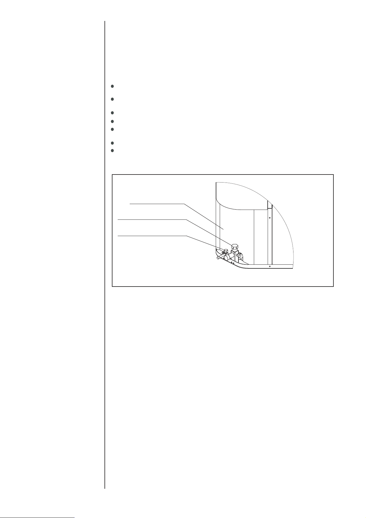
It will be more convenient to open the Service valve after removing the Underside
Clpboard
Underside Clapboard
. see the Fig.1
LARGE SERVICE VALVE
SMALL SERVICE VALVE
Fig.1
Underside Clapboard Location
1.2 LIMITATIONS
The unit should be installed in accordance with all National, State and Local Safety
Codes and the limitations listed below:
1.Limitations for the indoor unit, coil and appropriate accessories must also be observed.
2.The outdoor unit must not be installed with any duct work in the air stream. The outdoor fan is
the propeller type and is not designed to operate against any additional external static
pressure.
3.The maximum and minimum conditions for operation must be observed to assure a system
that will give maximum performance with minimum service.
4.This unit is not designed to operate with a low ambient kit. Do not modify the control system
to operate with any kind of Iow ambient kit.
5.The maximum allowable line length for this product is 150 feet(Just for Scroll compressor).
4
2.0 GENERAL
The outdoor units are designed to be connected to a matching indoor coil with sweat
connect lines. Sweat connect units are factory charged with refrigerant for a matching indoor coil plus 25 feet of field supplied lines.
Matching indoor coils are available with a thermostatic expansion valve or an orifice
for the most common usage. The orifice size and/or refrigerant charge may need to
be changed for some indoor-outdoor unit combinations, elevation differences or
total line lengths.
Page 5
SERVICE ACCESS
ALLOW 24” CLEARANCE
DETAIL A
KNOCKOUT
1-11/32” (34.5mm)
POWER WIRING
SEE DETAIL A
W
AIR DISCHARGE: ALLOW 60”
MINIMUM CLEARANCE.
AIR INLETS
LOUVERED PANELS
ALLOW 18”
MINIMUM
CLEARANCE
NOTE: GRILL APPEARANCE
MAY VARY.
CONTROL WIRING
7/8” (22.2mm)
HOLE
1-3/32” (27.8mm)
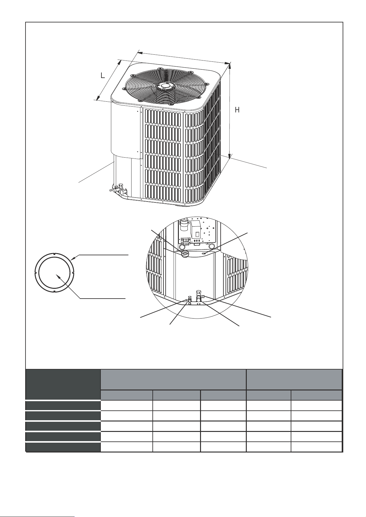
DIMENSIONAL DATA
MODEL SIZE
18
24 29-1/8[740] 29-1/8[740] 3 /8 3 /4
30 29-1/8[740] 29-1/8[740] 3 /8 3 /4
36 29-1/8[740] 29-1/8[740] 3 /8 7/8
42 29-1/8[740] 29-1/8[740] 3 /8 7/8
SERVICE
FITTING
LIQUID LINE
CONNECTION
FIG.2 DIMENSIONS
VAPOR LINE
CONNECTION
Dimensions (Inches)
"H" in. [mm] "W" in. [mm] "L" in. [mm]
24-15/16[633]
24-15/16[633]
28[710]
28[710] 3 /8 3 /4
24-15/16[633]
33-3/16[843]
33-3/16[843]
SERVICE
FITTING
Refrigerant Connection
Service Valve Size
Liquid in.
Vapor in.
5
Page 6
3.0 UNIT INSTALLATION
3.1 LOCATION
Before starting the installation, select and check the suitability of the location for both
the indoor and outdoor unit. Observe all limitations and clearance requirements. The
outdoor unit must have sufficient clearance for air entrance to the condenser coil, for air
discharge and for service access. See Fig.2
NOTE
For multiple unit installations, units must be spaced a minimum of 18 inches
apart. (Coil face to coil face.)
If the unit is to be installed on a hot sun exposed roof or a black-topped ground area, the
unit should be raised sufficiently above the roof or ground to avoid taking the accumulated layer of hot air into the outdoor unit.
Provide an adequate structural support.
3.2 GROUND INSTALLATION
The unit may be installed at ground level on a solid base that will not shift or settle, causing strain on the refrigerant lines and possible leaks. Maintain the clearances shown in
Fig.2 and install the unit in a level position.
Normal operating sound levels may be objectionable if the unit is placed directly under
windows of certain rooms (bedrooms, study, etc.).
Top of unit discharge area must be unrestricted for at least 60 inches above the unit.
WARNING
The outdoor unit should not be installed in an area where mud or ice could cause
personal injury.
Elevate the unit sufficiently to prevent any blockage of the air entrances by snow in
areas where there will be snow accumulation. Check the local weather bureau for the
expected snow accumulation in your area. Isolate the unit from rain gutters to avoid any
possible wash out of the foundation.
3.3 ROOF INSTALLATION
When installing units on a roof, the structure must be capable of supporting the total
weight of the unit, including a padded frame unit, rails, etc., which should be used to
minimize the transmission of sound or vibration into the conditioned space.
3.4 UNIT PLACEMENT
1. Provide a base in the pre-determined location.
2. Remove the shipping carton and inspect for possible damage.
3. Compressor tie-down bolts should remain tightened.
4. Position the unit on the base provided.
6
Page 7
CAUTION
This system uses R410A refrigerant which operates at higher pressure than
R-22. No other refrigerant may be used in this system. Gauge sets, hoses,
refrigerant containers, and recovery system must be designed to handle
R410A. If you are unsure, consult the equipment manufacturer.
The outdoor unit must be connected to the indoor coil using field supplied refrigerant
grade copper tubing that is internally clean and dry. Units should be installed only with
the tubing sizes for approved system combinations. The charge given is applicable for
total tubing lengths up to 25 feet.
NOTE
Using a larger than specified line size could result in oil return problems. Using
too small a line will result in loss of capacity and other problems caused by insufficient refrigerant flow. Slope horizontal vapor lines at least 1" every 20 feet
toward the outdoor unit to facilitate proper oil return.
3.5 PRECAUTIONS DURING LINE INSTALLATION
1. Install the lines with as few bends as possible. Care must be taken not to damage
the couplings or kink the tubing. Use clean hard drawn Copper tubing where no
appreciable amount of bending around obstruction is necessary, if soft copper must
be used, care must be taken to avoid sharp bends which may cause a restriction.
2. The lines should be installed so that they will not obstruct service access to the coil,
air handling system or filter.
3. Care must also be taken to isolate the refrigerant lines to minimize noise transmis sion from the equipment to the structure.
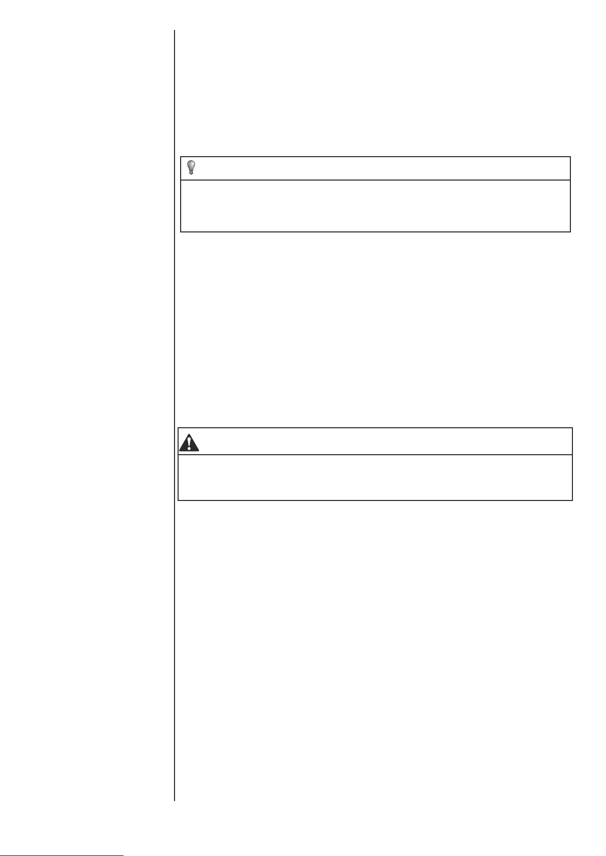
4. The vapor line and liquid line must be insulated with a minimum of 1/2" foam rubber
insulation (Armafiex or equivalent). Tape and suspend the refrigerant lines as shown.
DO NOT allow tube metal-to-metal contact. See Fig. 3.
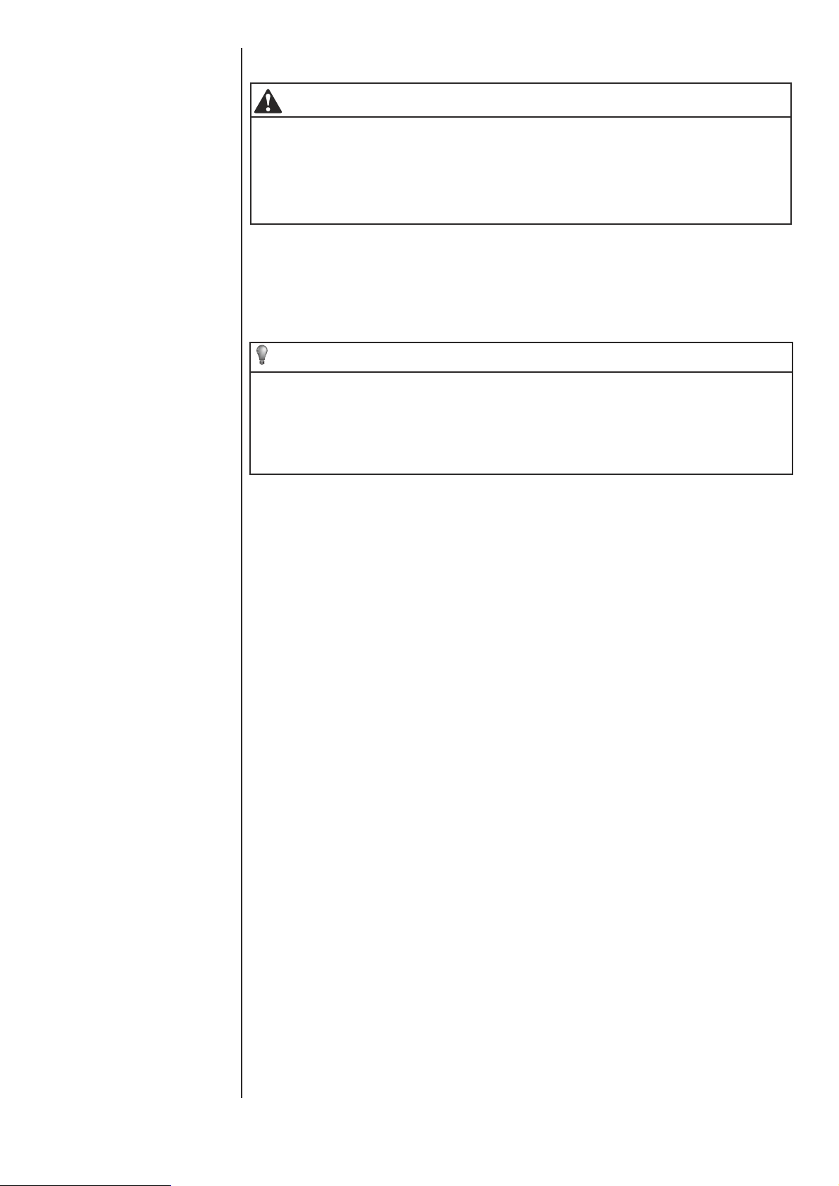
5. Use PVC piping as a conduit for all underground installations as shown in Fig. 4.
Buried lines should be kept as short as possible to minimize the build up of liquid
refrigerant in the vapor line during long periods of shutdown.
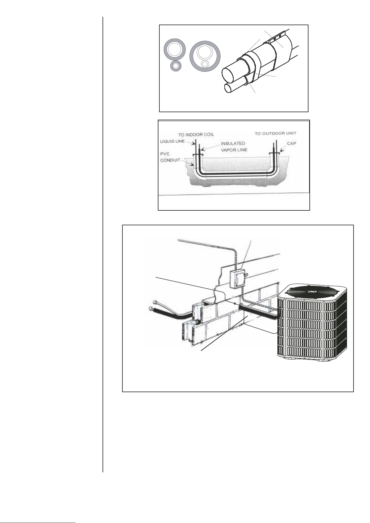
6. Pack fiberglass insulation and a sealing material such as perma gum around refrig erant lines where they penetrate a wall to reduce vibration and to retain some flexi bility.
7
Page 8
Sheet Meta l Hanger
Insulated Vapor Line
Correc t Incorrect
TO
POWER
SUPPLY
Tape
Insula te d Liquid Line
Fig.3 Tubing Hanger
Fig.4 Underground Installation
WEATHERPROOF
DISCONNECT
SWITCH
TO
INDOOR
BLOWER
TO
COIL
Seal opening(s) with
permagumor equivalent
24
V
c
o
nt
r
o
l
s
ign
al
NOTE:All outdoor wiring must be weather proof
Fig.5
Typical Installation
3.6 PRECAUTIONS DURING BRAZING OF LINES
All outdoor unit and evaporator coil connections are copper-to-copper and should be
brazed with a phosphorous-copper alloy material such as Silfos-5 or equivalent. DO
NOT use soft solder. The outdoor units have reusable service valves on both the liquid
and vapor connections. The total system refrigerant charge is retained within the
outdoor unit during shipping and installation. The reusable service valves are provided
to evacuate and charge per this instruction.
Serious service problems can be avoided by taking adequate precautions to assure an
internally clean and dry system.
8
Page 9

CAUTION
Dry nitrogen should always be supplied through the tubing while it is being
brazed, because the temperature required is high enough to cause oxidation
of the copper unless an inert atmosphere is provide. The flow of dry nitrogen
should continue until the joint has cooled. Always use a pressure regulator
and safety valve to insure that only low pressure dry nitrogen is introduced into
the tubing.Only a small flow is necessary to displace air and prevent oxidation.
3.7 PRECAUTIONS DURING BRAZING SERVICE VALVE
Precautions should be taken to prevent heat damage to service valve by wrapping a wet
rag around it as shown in Fig. 6. Also, protect all painted surfaces, insulation, during
brazing. After brazing cool joint with wet rag.
Valve can be opened by removing the plunger cap and fully inserting a hex wrench into
the stem and backing out counter-clockwise until valve stem just touches the chamfered retaining wall.
Connect the refrigerant lines using the following procedure:
1. Remove the cap and Schrader core from both the liquid and vapor service valve
service ports at the outdoor unit. Connect Iow pressure nitrogen to the liquid line
service port.
wet rag
2. Braze the liquid line to the liquid valve at the outdoor unit. Be sure to wrap the valve
body with a wet rag. Allow the nitrogen to continue flowing. Refer to the Tabular Data
Sheet for proper liquid line sizing.
3. Carefully remove the rubber plugs from the evaporator liquid and vapor connections
at the indoor coil.
4. Braze the liquid line to the evaporator liquid connection. Nitrogen should be flowing
through the evaporator coil.
5. Slide the plastic cap away from the vapor connection at the indoor coil. Braze the
vapor line to the evaporator vapor connection. Refer to the Table 1 for proper vapor
line sizing.
6. Protect the vapor valve with a wet rag and braze the vapor line connection to the
outdoor unit. The nitrogen flow should be exiting the system from the vapor service
port connection. After this connection has cooled, remove the nitrogen source from
the liquid fitting service port.
7. Replace the Schrader core in the liquid and vapor valves.
8. Leak test all refrigerant piping connections including the service port flare caps to be
sure they are leak tight. DO NOT OVER TIGHTEN (between 40 and 60 inch -lbs.
maximum).
9. Evacuate the vapor line, evaporator and the liquid line, to 500 microns or less.
service valve
Fig.6 Heat Protection
9
Page 10
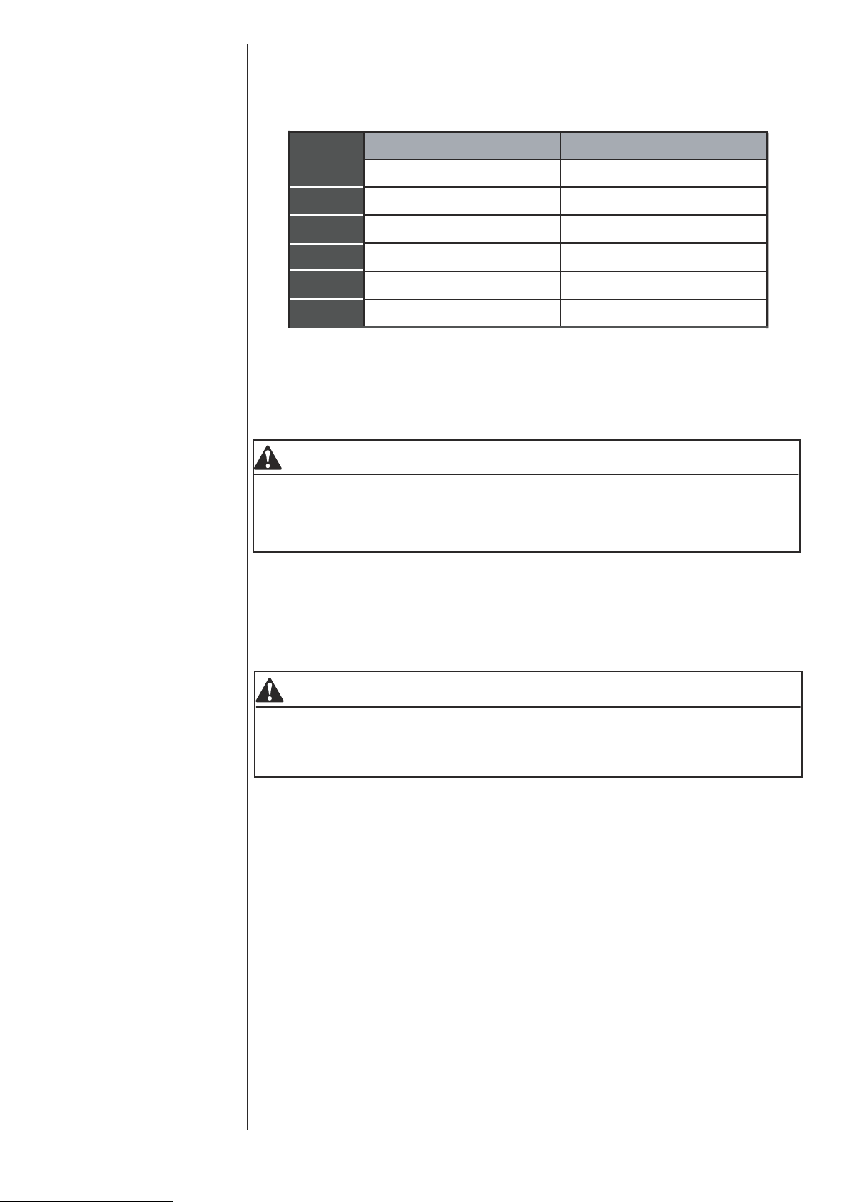
Table 1: Refrigerant Connections and Recommended Liquid and Suction Tube
Diameters (ln.)
LIQUID
MODEL SIZE
18
18
24
24
30
30
36
36
42
10. Replace cap on service ports. Do not remove the flare caps from the service ports
except when necessary for servicing the system.
Tube Diameter
3/8
3/8
3/8
3/8
3/8
SUCTION
Tube Diameter
3/4
3/4
3/4
7/8
7/8
CAUTION
Do not connect manifold gauges unless trouble is suspected. Approximately 3/4
ounce of refrigerant will be lost each time a standard manifold gauge is
connected.
11. Release the refrigerant charge into the system. Open both the liquid and vapor
valves by removing the plunger cap and with an hex wrench back out counter
-clockwise until valve stem just touches the chamfered retaining wall.
12. Replace plunger cap finger tight, then tighten an additional 1/12 turn (1/2 hex flat).
Cap must be replaced to prevent leaks.
WARNING
Never attempt to repair any brazed connections while the system is under pressure. Personal injury could result.
See "System Charge" section for checking and recording system charge.
3.8 UNIT MOUNTING
If elevating the heat pump, either on a flat roof or on a slab, observe the following guidelines.
1.The base pan provided elevates the heat pump 2” above the base pad.
2 . If elevating a unit on a flat roof , use 4”× 4”(or equivalent) stringers
positioned to distribute unit weight evenly and prevent noise and vibration
(See fig. 7) .
NOTE:Do not block drain openings shown in fig.7.
3. If unit must be elevated because of anticipated snow fall, secure unit and
elevating stand such that unit and/or stand will not tip over or fall off.
NOTE: To tie down unit, see 3.9.
10
Page 11

BASE PAD
(CONCRETE OR
OTHER SUITABLE
MATERIAL)
BASE PAN (BOTTOM VIEW) DO NOT
OBSTRUCT DRAIN HOLES
(SHADED)
ELEVATION ABOVE ANTICIPATED
SNOW IS NECESSARY
Fig.7 RECOMMENDED ELEVATED INSTALLATION
3.9 FACTORY-PREFERRED TIE-DOWN METHOD
Step 1: Prior to installing clear pad of debris.
IMPORTANT
Then cement pad must be made of HVAC-approved materials and must be the
proper thickness to accommodate fasteners.
Step 2: Center and level unit onto pad.
Step 3: Using L-shaped bracket to locate holes on concrete and drill pilot holes which is
at least 1/4” deeper than fastener being used.
IMPORTANT
Self drilling screws to base pan should not exceed 3/8” long to avoid damaging
coil.
Step 4: Using conventional practices to install brackets, tighten concrete fasteners and
self-tapping screws (See Fig.8).
: 1. One bracket for each side. For extra stability, 2 brackets for each side.
NOTE
2. Do not over-tighten the concrete fastener to avoid weakening the concrete.
IMPORTANT NOTE:
These instructions are intended to provide a method to tie-down system to cement slab
as a securing procedure for high wind areas. It is recommended to check Local Codes
for tie-down methods and protocols.
11
Page 12

The dimension see FIG.2
#7 X 3/8” Self Tapping Screws
(Don’t Exceed 3/8” long)
1/4” Χ 1-1/2” Hex Washer Head Concrete Screws
(3/16” Pilot Hole Needed. Pilot Hole Should Be1/4” Deeper
Than The Fastener Embedment)
3.10 REMOVING THE TOP PANEL AND MOTOR
Fig.8 FACTORY-PREFERRED TIE-DOWN METHOD
REQUIRED PARTS LIST
DETAIL B
SEE DETAIL B
Brackets:
2” width, 1/16” thickness,
height as required.
Available from distributor
or in market place.
1/2” bolt
NOTE:
Damage will occur to condenser unit
if you remove fan bolts prior to cover removal.
Fig. 9 COVER AND FAN
When motor requires changing follow the steps below:
Step 1: Go into electrical panel, disconnect motor power lines.
IMPORTANT NOTE
Disconnect main power to unit. Severe burns and electrical shock will occur if
you do not disconnect main power.
Step 2: Remove cover (be careful of motor wires)
Step 3: Be sure to place fan cover unit on the ground as indicated in Fig. 9
IMPROTANT NOTE
Do not place or lean fan blades on ground or against surface.
Step 4: Remove fan motor by removing 5/16” bolts from cover.
Step 5: Remove fan blade from motor by removing 1/2” bolt and place fan on the ground.
Step 6: Reverse removal process to reinstall the fan and motor.
IMPROTANT NOTE
When connecting motor wires be sure to check motor direction.
5/16” bolts
12
Page 13

4.0 ELECTRICAL CONNECTIONS
4.1 GENERAL INFORMATION & GROUNDING
Check the electrical supply to be sure that it meets the values specified on the unit
nameplate and wiring label.
Power wiring, control (Iow voltage) wiring, disconnect switches and over current
protection must be supplied by the installer. Wire size should be sized per req-uire
ments.
CAUTION
All field wiring must USE COPPER CONDUCTORS ONLY and be in accordance
with Local, National Fire, Safety & Electrical Codes. This unit must be grounded
with a separate ground wire in accordance with the above codes.
The complete connection diagram and schematic wiring label is located on the inside
surface of the unit service access panel and this instruction.
4.2 FIELD CONNECTIONS POWER WIRING
1. Install the proper size weatherproof disconnect switch outdoors and within sight of
the unit.
2. Remove the screws at the side of the corner panel. Slide corner panel down and
remove from unit. See Fig. 10.
3. Run power wiring from the disconnect switch to the unit.
4. Route wires from disconnect through power wiring opening provided and into the
unit control box.
CORNER
PANEL
POWER
WIRING
CONTROL
WIRING
Fig.10 Typical Field Wiring
5. Install the proper size time-delay fuses or circuit breaker, and make the power
supply connections.
6. Energize the crankcase heater if equipped to save time by preheating the compres sor oil while the remaining installation is completed.
NOTE: When changing the motor, remove top cover first.
13
Page 14

5.0 EVACUATION
It will be necessary to evacuate the system to 500 microns or less. If a leak is
suspected, leak test with dry nitrogen to locate the leak. Repair the leak and test again.
To verify that the system has no leaks, simply close the valve to the vacuum pump
suction to isolate the pump and hold the system under vacuum. Watch the micron
gauge for a few minutes. If the micron gauge indicates a steady and continuous rise,
it's an indication of a leak. If the gauge shows a rise, then levels off after a few minutes
and remains fairly constant, its an indication that the system is leak free but still
contains moisture and may require further evacuation if the reading is above 500
microns.
6 .0 INTERCONNECTING TUBING
6 .1 VAPOR AND LIQUID LINES
Keep all lines sealed until connection is made.
Make connections at the indoor coil first.
Refer to Li ne Size Information in Ta bles 2 and 3 for correct size and multipliers to be
used to determine capacity for various vapor line diameters and lengths of run. The
losses due to the lines being exposed to outdoor conditions are not included.
The factory refrigerant charge in the o
interc onnecting lines.
1/4” ± .3 oz. per foot
5/16” ± .4 oz. per foot
3/8” ± .6 oz . per foot
1/2” ± 1.2 oz . per foot
utdoor unit is s ufficient for 25 feet of
For
diff erent lengths, adjust the charge as indicated below.
6 .2 M AXIMUM LENGTH OF LINES
T h e maximum length of interconnecting line is 150 feet.
Always use the shortest length possible with a minimu m number of bends. Additional
compressor oil is not required for any length up to 150 feet.
NOTE: Excessively long refrigerant lines cause loss of equipment capacity.
6 .3 V ERTICAL SEPARATION
Keep the vertical separation to a minimum. Use the following g
installing the unit:
1. DO NOT exceed the vertical separations as indicated on Table 3.
2. It is recommended to use the smallest liquid line size permitted to minimize sys em charge which will maximize compressor reliability.
t
3. Table 3
may be used for sizing horizontal runs.
uidelines when
14
7.0 SYSTEM OPERATION -
7.1 COMPRESSOR CRANKCASE HEATER (CCH HEAT PUMP ONLY )
Refrigerant migration during the off cycle can result in a noisy start up. Add a crank
case heater to minimize refrigeration migration, and to help eliminate any start up
noise or bearing “wash out”.
All heaters are located on the lower half of the compressor shell. Its purpose is to drive
refrigerant from the compressor shell during long off cycles, thus preventing damage
to the compressor during start-up.
At initial start-up or after extended shutdown periods, make sure the heater is energized for at least 12 hours before the compressor is started. (Disconnect switch on and
wall thermostat off.)
Page 15

7.2 LINE SIZING
TABLE 2: SUCTION LINE LENGTH/SIZE VS CAPACITY MULTIPLIER(R410A)
System Capacity
Suction Line Connection Size
Suction Line Run - Feet
1 1/2 Ton 2 Ton 2 1/2 Ton 3 Ton 3 1/2 Ton
3/4" I.D. 3/4" I.D. 3/4" I.D. 7/8" I.D. 7/8" I.D.
5/8 Opt. 5/8 Opt. 5/8 Opt. 3/4 Opt. 3/4 Opt.
3/4* Std. 3/4* Std. 3/4* Std. 7/8* Std. 7/8* Std.
25'
50'
100'
150'
Optional 1.00 1.00 1.00 1.00 1.00
Standard 1.00 1.00 1.00 1.00 1.00
Optional 0.97 0.97 0.97 0.98 0.98
Standard 0.98 0.98 0.98 0.99 0.98
Optional 0.94 0.94 0.94 0.96 0.95
Standard 0.95 0.95 0.96 0.97 0.97
Optional 0.90 0.90 0.90 0.94 0.91
Standard 0.92 0.92 0.93 0.95 0.
96
NOTES:
* Standard size
Using suction line larger than shown in chart will result in poor oil return and is not recommended.
TABLE 3 :LIQUID LINE SIZE (R-410A)
Liquid Line Size
Total Equivalent Length - Feet
System
Capacity
1 1/2 Ton 3/8"
2 Ton 3/8"
3 Ton
Line Size
Connection Size
(Inch I.D.)
3/8" 2 1/2 Ton
3/8"
3/8"
Compressor
Type
Scroll
Scroll
Scroll
Scroll
Scroll 3 1/2 Ton
Line Size
Connection And
Line Size
(Inch I.D.)
1/4 25 40 25 9 N/A N/A
5/16 25 50 62 58 53 49
3/8* 25 50 75 72 70 68
1/4 23 N/A N/A N/A N/A N/A
5/16 25 36 29 23 16 9
3/8* 25 50 72 70 68 65
1/4 25 N/A N/A N/A N/A N/A
5/16 25 49 38 27 17 6
3/8* 25 50 68 65 62 58
5/16 25 50 37 22 7 N/A
3/8* 25 50 68 63 58 53
5/16 25 23 4 N/A N/A N/A
3/8* 25 50 43 36 30 24
25 50 75 100 125 150
Outdoor unit above or below indoor coil
Maximum Vertical Separation - Feet
NOTES:
* Standard line size
N/A Application not recommended.
15
Page 16

7.3 PROTECTION FUNCTION INTRODUCTION
Sensor T3 (condenser pipe temperature) and T4 (outdoor ambient temperature)
When open-circuit, compressor, outdoor fan motor and reverse valve will be OFF.
When T4 < 5 °F, compressor will stop.If the electrical heater kit is installed in the
indoor unit, the outdoor unit would provide a signal to drive up the heater.
When T4 > 10.4 °F, compressor will restart
Discharge temperature protection
When discharge temp. > 275 °F, compressor will stop.
When discharge temp. < 194 °F, compressor will restart.
(Heat pump only
High perssure protection
When high pressure > 638 PSIG, compressor and outdoor fan motor will stop.
When high pressure < 464 PSIG, compressor and outdoor fan motor will restart
(3 minutes delay necessary).
Low pressure protection
Low pressure < 21 PSIG, compressor and outdoor fan motor will stop.
Low pressure > 44 PSIG, compressor and outdoor fan motor will restart
(3 minutes delay necessary).
In stand-by status, the compressor will not start in low pressure protection.
Within 30 mins, if 4 protection cycles occurs, system will restore after power cut-down.
7.4 DEFROST MODE INTRODUCTION
Start-up conditions of defrost mode:
When JUMP switch is set to “1”(See in Fig 11), the mode will start up in either of
the two following conditions:
1. Compressor operating, when T4 is > 28.4 °F and T3 is < 32 °F last for 40 minutes;
2. Compressor operating, when T4 is < 28.4 °F and T3 is < 32 °F last for 50 minutes.
When JUMP switch is set to “0”:
Compressor operating, when T3 is < 32 °F last for 30 minutes.
Shut-down conditions of defrost mode:
The mode will shut down in either of the two following conditions:
1. The defrosted time lasting for 10 minutes;
2. T3 is ≥ 77 °F.
16
JUMP Switch
Fig.11 JUMP S witch Locatio n in the P CB Board
Page 17

8.0 CHECKING REFRIGERANT CHARGE
Charge for all systems should be checked against the Charging Chart inside the
access corner panel.
IMPORTANT:Do not operate the compressor without charge in system. Additio n of
R - 410A will raise pressures (vapor, liquid and discharge).
f adding R - 410A raises both vapor pressure and temperature, the unit is over -
I
c harged.
IMPORTANT: Use industry - approved charging methods to ensure proper system
charge.
8 .1 CHARGING BY LI Q UID PRESSURE
The liquid pressure method is used for charging systems in the cooling and heating
mode. The service port on the liquid (small valve) and suction (large valve) is used
for this purpose.
Verify th
maximum airflow for this system size. Read and record the outdoor ambient tem -
erature. Read and record the liquid and suction pressures at the ports on the liquid
p
and suction valves.
If refrigerant lines are sized using the n ameplate charge, the correct liquid pressure is
found at the intersection of the suction pressure a
1. Remove refrigerant charge if the liquid pressure is above the chart value.
2. Add refrigerant charge if the liquid pressure is below the chart value.
8 .2 CHARGING BY WEIGHT
at the outdoor unit is running and the indoor air mover is delivering the
nd the outdoor ambient.
For a new installation, evacuation of interconnecting tubing and indoor coil is
adeq uate; otherwise, evacuate the entire system.
charge required for 25 ft. of standard size interconnecti ng liquid line. Calculate actua l
charge required with installed liquid line size and length, please see 6.1 of table of
contents.
With an accurate scale (+/ - 1 oz.) or volumetric char ging device, adjust charge
diff erence between that s
system Installation. if the entire system has been evacua ted, add the total calculated
charge.
hown on the unit data plate and that calculated for the new
Note that charge value includes
8.3 FINAL LEAK TESTING
After the unit has been properly evacuated and charged, a halogen leak detector
should be used to detect leaks in the system. All piping within the condensing unit,
evaporator, and interconnec ting tubing should be check
detected, the refrigerant should be recovered before repairing the leak. The Clean Air
Act prohibits releasing refrigerant into the atmosphere .
ed for leaks. If a leak is
9.0 OWNER INSTRUCTIONS
Assist owner with processing Warranty cards and/or online registration. Review Owners
Guide and provide a copy to the ower and guidance on proper operation and mainteance. Instruct the owner or the operator how to start, stop and adjust temperature
setting. The installer should instruct the owner on proper operation and maintenance of
all other system components.
17
Page 18
9.1 MAINTENANCE
1.
. Dirt should not be allowed to accumulate on the outdoor coils or other parts in the air
circuit. Clean as often as necessary to keep the unit clean. Use a brush, vacuum
cleaner attachment, or other suitable means.
2. The outdoor fan motor is permanently lubricated and does not require periodic oiling.
3. If the coil needs to be cleaned, it should be washed with Calgon Coilclean (mix one
part Coilclean to seven parts water). Allow solution to remain on coil for 30 minutes
before rinsing with clean water. Solution should not be permitted to come in contact
with painted surfaces.
4. Refer to the furnace or air handler instructions for filter and blower motor maintenance.
5. The indoor coil and drain pan should be inspected and cleaned regularly to assure
proper drainage.
CAUTION
It is unlawful to knowingly vent, release or discharge refrigerant into the open air
during repair, service, maintenance or the final disposal of this unit. When the
system is functioning properly and the owner has been fully instructed, secure the
owner’s approval.
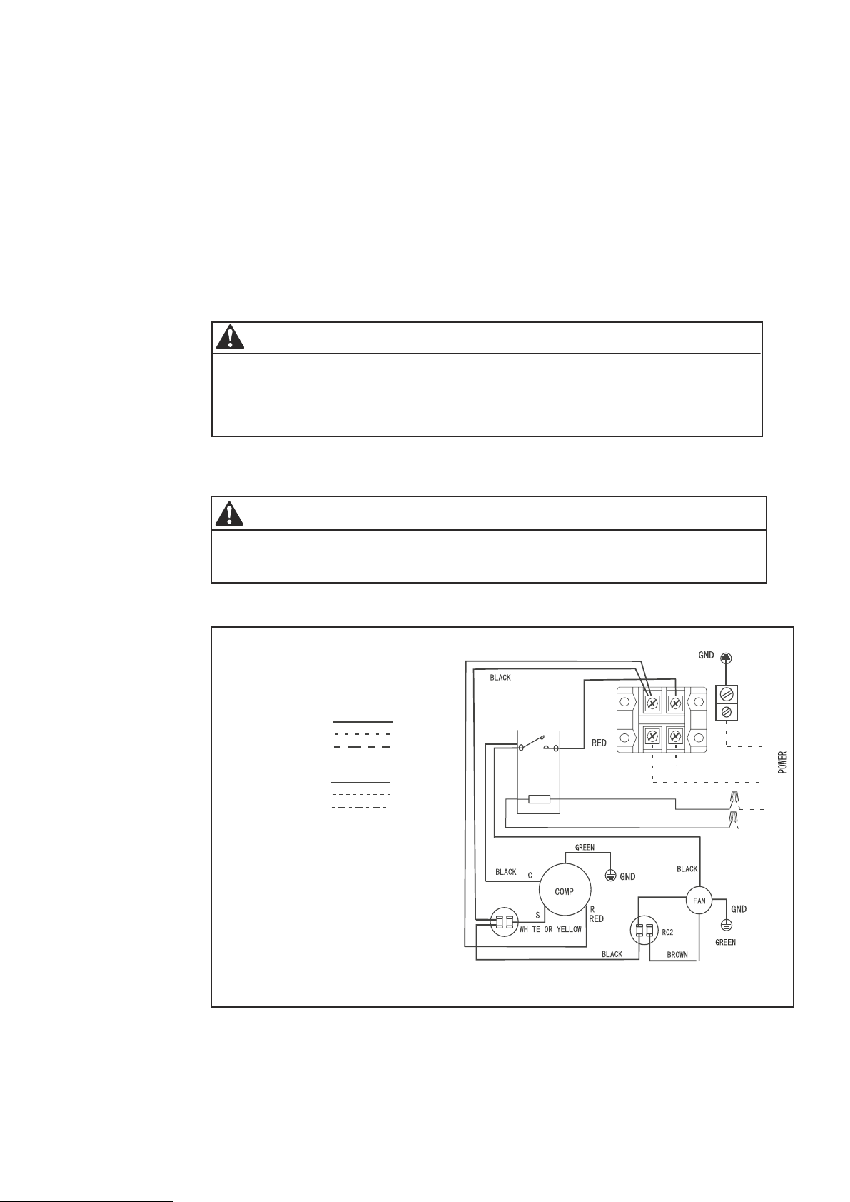
10.0 WIRING DIAGRAM
CAUTION
These un it s must be wired and in st al le d in a ccordance with all National and
Local Safety Codes.
CC COMPRESSORCONTACTOR
COMP COMPRESSOR
RC1 RUN CAPACITOR1
RC2 RUN CAPACITOR2
LINEVO LTAGE
FACTORYSTANDARD
FIELDINSTALLED
OPTIONAL
FACTORY
LOW
VOLTAGE
FACTORYSTANDARD
FIELDINSTALLED
FACTORYOPTIONAL
USECOPPERCONDUCTORSONLY
WARNING:
CABINETMUSTBEPERMANMENTLY GROUNDE D
ANDALLWIRINGTOCONFORMTO I.E.C, N.E.C,
C.E.C, C.L.C, ANDLOCALCODESA S APPLICABLE
REPLACEMENTWIREMUSTBETHESAMEGAUG E
AND INSULATION TYPE ASORIGINALWIRE.
L1
A1
RC1
T1
CC
A2
Terminal Block
L2
L1
BLACK
YELLOW
ORANGE
GND
L1
L2
T
A T
S O
C
M
R E
Y
O
H T
T
18
Fig.12 O utdoor U nit Wiring Diagram for A/C Systems(208/23 0V 1P 60 Hz ).
Page 19

THERMOSTAT
C
R
Y
G
GREE N
R ED
BLACK
YE LLO W
BLACK
INDOOR UNIT
Suggestion: When choosing a thermostat, choose KJR-25B or a non-programmable
electric thermostat series . Please refer to thermostat electrical manual for wiring
schematic.
CC COMPRESSORCONTACTOR
CCH
CRANKCASEHEATER
COMPRESSOR
COMP
DEFROST CONTROL
DFC
AMBIENT TEMPERATURE
T4
T3
PIPE TEMPERATURE
HPC HIGHT PRESSURECUT-OUTCONTROL
PC LOW PRESSURECUT-OUTCONTROL
L
OFM OUTDOOR FAN MOTOR
RC1 RUN CAPACITOR1
RC2 RUN CAPACITOR2
RV REVER
GND GROUNDCHASSIS
HGS HOT GASSENSOR
LINEVO LTAGE
FACTORYSTANDARD
FIELDINSTALLED
FACTORY
LOW
VOLTAGE
FACTORYSTANDARD
FIELDINSTALLED
FACTORYOPTIONAL
USECOPPERCONDUCTORSONLY
WARNING :
CABINETMUSTBEPERMANMENTLY
GROUNDEDANDALLWIRINGTOCONFORMTO
I.E.C, N.E.C, C.E.C, C.L.C, ANDLOCALCODESA S
APPLICABLE REPLACEMENTWIREMUSTBETHESAM E
GAUGEAND INSULATION TYPE ASORIGINALWIRE.
SING VALVE
OPTIONAL
G
R
C
OUTDOOR UNIT
Fig.13 Control Wiring for A/C Systems.
21
L1
A1
ORANGE
OFM
CC
YELLOW
22
T1
A2
HPC
YELLOW
HGS
Y
CCH
LPC
CN20
FAN
CN15
C
T4
T3
Terminal block
L1 L2
t
R
u o
C
Y
C
Y
DFC
B
D
C
RV
RV
RED
BLACK
YELLOW
BLUE
PURPLE
GND
L1
L2
R
C
Y
B
W2
TA
T
SO
M
R
E
HT
OT
Fig.14 Outdoor Unit Wiring Diagram for H/P Sy stem s(208/230V 1P 60Hz).
19
Page 20

W2
B
C
R
Y
G
THERMOSTAT
INDOOR UNIT
Suggestion: When choosing a thermostat, choose KJR-25B or a non-programmable electric
thermostat series . Broken lines means H/P system with electric heating. Please refer to
thermostat electrical manual for wiring schematic.
TABLE 4: Electrical Data:
Model Min. Circuit Ampacity(A) Maximum Circuit Protector(A)
18AC
24AC
30AC
36AC
42AC
RED
GREEN
R
G
WHITE
BLACK
w1
C
RED
R Y
BLACK
C
OUTDOOR UNIT
Fig.15 Control Wiring for H/P Systems.
12.3
17.9
18.7
21.9
23.4
YELLOW
20
30
30
35
40
BLUE
B
PURPLE
D
20
18HP
24HP
30HP
36HP
42HP
NOTES: AC:Air Conditioner; HP :Heat Pump
12.3
17.9
18.7
21.9
23.4
20
30
30
35
40
Page 21

79 09 N .W. 54th Street,
Mi am i, F L 33 16 6 US A
Ph on e: + 1 (3 05 ) 59 3-8358
Fax: + 1 (305) 593 8212
e- ma il : sa le s@klimaire.com
ww w.klimaire .c om
 Loading...