

KLIC-N-KUT KNK Force User Manual

The KNK Force with C3 User Manual
http://knkusa.com/
May 11, 2018
Do NOT read this entire manual… unless you want to.
• Chapters 1 - 3 are very important in terms of setting up your Force and learning cut settings.
• Chapter 4 covers how to export SVGs from the supported design programs. Please read the section on the
design program you’ll be using.
• Chapter 5 covers the dual head feature and how to best use Force accessory tools.
• Chapter 6 is for those owners wanting to perform print and cut applications.
• Chapter 7 covers the Force rotary tool.
• Chapter 8 covers popular materials and applications used on the Force.
It’s not practical to print this entire manual because:
• It’s a waste of paper and ink if you only ever need certain sections.
• The live links to videos, blog posts, products, etc. will not work.
• The user manuals are updated from time to time.
• You cannot search on individual words.

Table of Contents
CHAPTER 1 INTRODUCTION TO THE KNK FORCE ......................................................................................................................... 1-1
1.01 USER MANUAL OPTIONS .................................................................................................................................................................. 1-2
1.02 SAFETY AND WARNINGS .................................................................................................................................................................. 1-2
1.03 WARRANTY ..................................................................................................................................................................................... 1-3
1.04 SUPPORT ........................................................................................................................................................................................ 1-3
1.05 UNPACKING ..................................................................................................................................................................................... 1-3
1.06 CONTENTS ...................................................................................................................................................................................... 1-4
1.07 PARTS OF THE KNK FORCE ............................................................................................................................................................. 1-4
1.08 BLADE HOLDERS AND BLADES.......................................................................................................................................................... 1-5
1.08.1 Blade Installation ........................................................................................................................................................................................... 1-5
1.08.2 Setting the Blade Tension (BT) ..................................................................................................................................................................... 1-7
1.09 ACCESSORY TOOLS ......................................................................................................................................................................... 1-8
1.10 PREPARING AND CARING FOR THE CUTTING MAT .............................................................................................................................. 1-8
1.10.1 Tips on Using the Cutting Mat ....................................................................................................................................................................... 1-8
1.10.2 Cleaning and Replenishing the Cutting Mat .................................................................................................................................................. 1-8
1.11 INSTALLING THE PINCH WHEELS ....................................................................................................................................................... 1-9
1.12 OTHER USEFUL TOOLS AND SUPPLIES ............................................................................................................................................ 1-11
1.13 REVIEW OF CHAPTER 1 ................................................................................................................................................................. 1-13
1.13.1 Miscellaneous Things to Note: .................................................................................................................................................................... 1-13
CHAPTER 2 GETTING STARTED ....................................................................................................................................................... 2-1
2.01 WHAT IS C3? .................................................................................................................................................................................. 2-1
2.02 SETTING UP THE FORCE .................................................................................................................................................................. 2-1
2.02.1 Terminology................................................................................................................................................................................................... 2-1
2.02.2 Choosing a Connection Mode ....................................................................................................................................................................... 2-2
2.02.3 Connecting and Launching C3 ...................................................................................................................................................................... 2-2
2.03 STANDALONE (AD HOC) CONNECTION .............................................................................................................................................. 2-4
2.03.1 First Time Standalone Mode ......................................................................................................................................................................... 2-4
2.03.2 Switching to Standalone Mode after Being in Another Mode........................................................................................................................ 2-4
2.04 ETHERNET CONNECTION .................................................................................................................................................................. 2-5
2.05 WI-FI CONNECTION ......................................................................................................................................................................... 2-6
2.05.1 Obtaining the Wi-Fi IP Address ..................................................................................................................................................................... 2-6
2.05.2 Setting a Static IP .......................................................................................................................................................................................... 2-7
2.06 SETUP FOR COMMUNICATION TESTING AND DRAWING ....................................................................................................................... 2-8
2.06.1 Selecting a Test File ...................................................................................................................................................................................... 2-8
2.06.2 Preparing the Force for Drawing ................................................................................................................................................................... 2-9
2.06.3 Setting the Z Origin ..................................................................................................................................................................................... 2-10
2.06.4 Entering Settings ......................................................................................................................................................................................... 2-12
2.06.5 Setting the XY Origin and Drawing ............................................................................................................................................................. 2-12
2.07 C3 SCREENS AND MISCELLANEOUS SETUP ..................................................................................................................................... 2-13
2.07.1 C3 Tabs ....................................................................................................................................................................................................... 2-13
2.07.2 Choosing Units ........................................................................................................................................................................................... 2-16
2.07.3 Naming Your Force ..................................................................................................................................................................................... 2-16
2.08 REVIEW OF CHAPTER 2 ................................................................................................................................................................. 2-17
2.08.1 Miscellaneous Things to Note ..................................................................................................................................................................... 2-17
2.08.2 Quick Guide: Setting the Z Origin ............................................................................................................................................................... 2-17
CHAPTER 3 CUTTING ......................................................................................................................................................................... 3-1
3.01 WHAT YOU NEED TO UNDERSTAND ABOUT CUTTING ......................................................................................................................... 3-1
You Have To Make Mistakes ................................................................................................................................................................................... 3-1
Begin with Easy Materials and Easy Shapes ........................................................................................................................................................... 3-1
Use the Correct Blade for the Material You Are Cutting .......................................................................................................................................... 3-1
Set the Z Origin When Required .............................................................................................................................................................................. 3-1
Understand the Cut Settings .................................................................................................................................................................................... 3-2
Perform Test Cuts! ................................................................................................................................................................................................... 3-2
Record Your Successes ........................................................................................................................................................................................... 3-2
Keep the Cutting Mat Clean and Sticky ................................................................................................................................................................... 3-2
Know Where Your Images Will Cut .......................................................................................................................................................................... 3-3
Don’t Get Frustrated, Get Help! ............................................................................................................................................................................... 3-3
3.02 CUT SETTINGS IN C3 ....................................................................................................................................................................... 3-3

3.02.1 Passes (P) ..................................................................................................................................................................................................... 3-4
3.02.2 Cutting Depth (CD) / Ending Depth (ED) ...................................................................................................................................................... 3-5
3.02.3 Starting Depth (SD) ....................................................................................................................................................................................... 3-5
3.02.4 Cutting Speed (CS) ....................................................................................................................................................................................... 3-6
3.02.5 Up Speed (US) .............................................................................................................................................................................................. 3-6
3.02.6 Plunge Speed (PS) ....................................................................................................................................................................................... 3-6
3.02.7 Lift Speed (LS) .............................................................................................................................................................................................. 3-7
3.02.8 Cutting Tool (CT) ........................................................................................................................................................................................... 3-7
3.02.9 Blade Offset (BO) .......................................................................................................................................................................................... 3-7
3.02.10 Path Direction .............................................................................................................................................................................................. 3-8
3.02.11 Closed Path Overcut (CPO) ........................................................................................................................................................................ 3-9
3.02.12 Optimize Cut Order (OCO) .......................................................................................................................................................................... 3-9
3.02.13 Defaults ..................................................................................................................................................................................................... 3-10
3.02.14 Download an SVG Preset (Saving a File) ................................................................................................................................................. 3-10
3.03 BLADE TENSION (BT) .................................................................................................................................................................... 3-10
3.04 CONTROLLING WHERE IMAGES WILL CUT ....................................................................................................................................... 3-10
3.04.1 Portrait versus Landscape Cutting .............................................................................................................................................................. 3-11
3.04.2 Modes for Cutting (or Engraving, Embossing, etc.) .................................................................................................................................... 3-12
3.04.3 Where Shapes Will Cut ............................................................................................................................................................................... 3-12
3.04.4 Changing Where Images Will Cut ............................................................................................................................................................... 3-16
3.05 PERFORMING A CUT WITH THE BLADE HOLDER................................................................................................................................ 3-17
3.06 CALIBRATING THE FORCE’S SIZING RESOLUTION ............................................................................................................................. 3-20
3.07 REVIEW OF CHAPTER 3 .................................................................................................................................................................. 3-22
3.07.1 Summary of Cut Settings ............................................................................................................................................................................ 3-22
3.07.2 Miscellaneous Things to Note ..................................................................................................................................................................... 3-23
3.07.3 Quick Guide: Performing a Cut with the Blade Holder ................................................................................................................................ 3-24
SETTINGS FORM FOR CUTTING MATERIALS ON THE KNK FORCE
1
............................................................................................................ 3-25
SUGGESTED CUT SETTINGS FOR VARIOUS MATERIALS ON THE KNK FORCE
1
........................................................................................... 3-26
CHAPTER 4 MORE ABOUT C3 ........................................................................................................................................................... 4-1
4.01 IMPORTING .SVG FILES ................................................................................................................................................................... 4-1
4.01.1 Importing Single Layer SVG Files ................................................................................................................................................................. 4-1
4.01.2 Importing Multi-layer SVG Files .................................................................................................................................................................... 4-2
4.02 PREPARING .SVG FILES FROM OTHER APPLICATIONS ....................................................................................................................... 4-3
4.02.1 SVG Files from Make The Cut (MTC) ........................................................................................................................................................... 4-4
4.02.2 SVG Files from Sure Cuts a Lot (SCAL) ....................................................................................................................................................... 4-7
4.02.3 SVG Files from Adobe Illustrator (AI) .......................................................................................................................................................... 4-11
4.02.4 SVG Files from Inkscape ............................................................................................................................................................................ 4-14
4.02.5 SVG Files from Corel Draw (CD) ................................................................................................................................................................ 4-18
4.02.6 SVG Files from KNK Studio ........................................................................................................................................................................ 4-21
4.02.7 SVG Files from Popup Card Studio (PCS) ................................................................................................................................................. 4-21
4.02.8 Other SVG Files .......................................................................................................................................................................................... 4-23
4.03 UPDATING C3 ............................................................................................................................................................................... 4-23
4.03.1 Verifying Current Version and Available Version ........................................................................................................................................ 4-23
4.03.2 Downloading and Installing an Update........................................................................................................................................................ 4-24
4.03.3 Updating C3 Using A File Download ........................................................................................................................................................... 4-25
4.04 REVIEW OF CHAPTER 4 ................................................................................................................................................................. 4-27
4.04.1 Quick Guide for Preparing Images for C3 ................................................................................................................................................... 4-27
4.04.2 Quick Guide for Controlling Where Shapes Will Cut ................................................................................................................................... 4-27
4.04.3 Quick Guide for Changing Cut Direction ..................................................................................................................................................... 4-28
4.04.4 Miscellaneous Things to Note ..................................................................................................................................................................... 4-28
4.04.5 Updating C3 ................................................................................................................................................................................................ 4-28
CHAPTER 5 UTILIZING FORCE ACCESSORY TOOLS AND THE DUAL HEADS ........................................................................... 5-1
5.01 WHAT DUAL HEADS MEAN ............................................................................................................................................................... 5-1
5.02 CALIBRATING TWO TOOLS FOR ALIGNMENT ....................................................................................................................................... 5-1
5.03 GENERAL GUIDELINES WHEN USING ACCESSORY TOOLS .................................................................................................................. 5-3
5.04 DRAWING WITH A PEN OR GLUE PEN ................................................................................................................................................ 5-3
5.05 EMBOSSING AND SCORING ............................................................................................................................................................... 5-3
5.06 ENGRAVING .................................................................................................................................................................................... 5-4
5.07 USING THE PUNCH TOOL ................................................................................................................................................................. 5-5
5.08 USING THREE TOOLS IN THE KNK FORCE ......................................................................................................................................... 5-5
5.08.1 Return to Origin Method ................................................................................................................................................................................ 5-5
5.08.2 Registration Mark Method ............................................................................................................................................................................. 5-8
5.09 REVIEW OF CHAPTER 5 ................................................................................................................................................................. 5-12

5.09.1 Miscellaneous Things to Note ..................................................................................................................................................................... 5-12
5.09.2 Quick Guide: Calibrating Two Tools for Alignment ..................................................................................................................................... 5-12
5.09.3 Quick Guide: Three Tools – Return to Origin Method ................................................................................................................................ 5-12
5.09.4 Quick Guide: Three Tools – Registration Mark Method ............................................................................................................................. 5-13
SETTINGS FORM FOR FORCE ACCESSORY TOOLS
1
.................................................................................................................................. 5-14
SUGGESTED SETTINGS FOR VARIOUS FORCE ACCESSORIES
1
.................................................................................................................. 5-15
CHAPTER 6 PRINT AND CUTS ........................................................................................................................................................... 6-1
6.01 WHAT IS A PRINT AND CUT (PNC)? ................................................................................................................................................. 6-1
6.02 WHAT IS A PNC CALIBRATION? ........................................................................................................................................................ 6-2
6.03 WHAT YOU NEED FOR CALIBRATING ................................................................................................................................................. 6-2
6.04 PRINTING THE CALIBRATION FILE ...................................................................................................................................................... 6-2
6.04.1 Printing from Make the Cut ........................................................................................................................................................................... 6-3
6.04.2 Printing from SCAL ....................................................................................................................................................................................... 6-5
6.04.3 Printing from Inkscape .................................................................................................................................................................................. 6-6
6.05 PREPARING TO CUT ......................................................................................................................................................................... 6-8
6.06 PERFORMING THE REGISTRATION ALIGNMENT ................................................................................................................................... 6-9
6.07 ADJUSTING THE X AND Y OFFSETS FOR THE ELECTRONIC EYE ......................................................................................................... 6-11
6.08 AUTOMATIC PNC .......................................................................................................................................................................... 6-12
6.08.1 Registration Marks for Auto PNC ................................................................................................................................................................ 6-13
6.08.2 Performing the Automatic PNC ................................................................................................................................................................... 6-13
6.08.3 Setting the Origin for Automatic PNC.......................................................................................................................................................... 6-14
6.09 PRINT AND CUT TIPS ..................................................................................................................................................................... 6-15
6.10 PREPARING NEW PNC FILES IN MTC ............................................................................................................................................. 6-16
6.10.1 Using the Reg Mark Files in MTC .............................................................................................................................................................. 6-16
6.10.2 Moving Shapes to New Layers and Exporting ............................................................................................................................................ 6-17
6.10.3 The Shape Outline Issue in MTC ................................................................................................................................................................ 6-18
6.11 PREPARING NEW PNC FILES IN SCAL ........................................................................................................................................... 6-19
6.11.1 Using the Reg Marks in SCAL .................................................................................................................................................................... 6-19
6.11.2 Moving Shapes to New Layers and Exporting ............................................................................................................................................ 6-20
6.12 PREPARING NEW PNC FILES IN INKSCAPE ...................................................................................................................................... 6-21
6.12.1 Using the Reg Mark Files in Inkscape......................................................................................................................................................... 6-21
6.12.2 Moving Shapes to New Layers and Saving ................................................................................................................................................ 6-21
6.13 PREPARING NEW PNC FILES IN ADOBE ILLUSTRATOR ..................................................................................................................... 6-22
6.13.1 Using the Reg Mark Files in Adobe Illustrator ............................................................................................................................................. 6-22
6.13.2 Moving Shapes to New Layers and Saving ................................................................................................................................................ 6-23
6.14 CREATING YOUR OWN REGISTRATION MARKS ................................................................................................................................ 6-23
6.15 REVIEW OF CHAPTER 6 ................................................................................................................................................................. 6-25
6.15.1 Miscellaneous Things to Note ..................................................................................................................................................................... 6-25
6.15.2 Quick Guide: Performing a Manual Detection PNC .................................................................................................................................... 6-25
6.15.3 Quick Guide: Performing an Automatic Detection PNC .............................................................................................................................. 6-26
CHAPTER 7 ROTARY TOOL ............................................................................................................................................................... 7-1
7.01 IMPORTANT SAFETY AND OPERATING CONSIDERATIONS .................................................................................................................... 7-2
7.02 CONTENTS IN THE ROTARY TOOL KIT................................................................................................................................................ 7-2
7.03 SETTINGS FOR THE ROTARY TOOL ................................................................................................................................................... 7-3
7.04 DETERMINING SETTINGS FOR CUTTING A NEW MATERIAL .................................................................................................................. 7-4
7.04.1 Measure the Thickness of the Material ......................................................................................................................................................... 7-4
7.04.2 Surface Height............................................................................................................................................................................................... 7-5
7.04.3 CD/ED Calculator .......................................................................................................................................................................................... 7-5
7.05 PEN TEST FOR VERIFYING CD/ED BEFORE CUTTING ........................................................................................................................ 7-6
7.06 ATTACHING A DRILL BIT TO THE ROTARY TOOL ................................................................................................................................. 7-8
7.07 ATTACHING THE ROTARY TOOL TO THE KNK FORCE ......................................................................................................................... 7-9
7.07.1 Attaching the Adaptor to the Blade Holder Seat ........................................................................................................................................... 7-9
7.07.2 Inserting the Rotary Tool into the Adaptor .................................................................................................................................................. 7-10
7.08 ENGRAVING .................................................................................................................................................................................. 7-12
7.09 CUTTING ....................................................................................................................................................................................... 7-13
7.09.1 Things to Keep in Mind ............................................................................................................................................................................... 7-13
7.09.2 Important Checklist Before You Cut! .......................................................................................................................................................... 7-13
7.10 DESIGN CONSIDERATIONS ............................................................................................................................................................. 7-13
7.11 REVIEW OF CHAPTER 7 ................................................................................................................................................................. 7-15
7.11.1 Summary or Rotary Tool Settings ............................................................................................................................................................... 7-15
7.11.2 Miscellaneous Things to Note ..................................................................................................................................................................... 7-15
7.11.3 Quick Guide: Pen Test ................................................................................................................................................................................ 7-16

7.11.4 Quick Guide: Test Cutting with the Rotary Tool .......................................................................................................................................... 7-16
SETTINGS FORM FOR FORCE ROTARY TOOL
1
.......................................................................................................................................... 7-18
SUGGESTED ENGRAVING SETTINGS FOR FORCE ROTARY TOOL
1
............................................................................................................. 7-19
CHAPTER 8 TIPS ON CUTTING SPECIFIC MATERIALS .................................................................................................................. 8-1
8.01 CARDSTOCK AND PAPER .................................................................................................................................................................. 8-1
Selecting Cardstock and Paper ................................................................................................................................................................................ 8-1
Settings .................................................................................................................................................................................................................... 8-1
Troubleshooting ........................................................................................................................................................................................................ 8-1
8.02 CHIPBOARD ..................................................................................................................................................................................... 8-2
Selecting Chipboard ................................................................................................................................................................................................. 8-2
Settings .................................................................................................................................................................................................................... 8-3
Troubleshooting ........................................................................................................................................................................................................ 8-3
8.03 VINYL ............................................................................................................................................................................................. 8-3
Types of Vinyl ........................................................................................................................................................................................................... 8-3
Settings .................................................................................................................................................................................................................... 8-4
Applying Vinyl ........................................................................................................................................................................................................... 8-4
8.04 FABRIC AND FELT ............................................................................................................................................................................ 8-5
8.05 HEAT TRANSFER VINYL (HTV) ......................................................................................................................................................... 8-5
Types of Heat Transfer Vinyl .................................................................................................................................................................................... 8-5
Cutting Iron-On ......................................................................................................................................................................................................... 8-6
Adhering Iron-On ...................................................................................................................................................................................................... 8-6
8.06 RHINESTONE TEMPLATES ................................................................................................................................................................ 8-7
Cutting Rhinestone Template Material ..................................................................................................................................................................... 8-7
Weeding and Brushing in Rhinestones .................................................................................................................................................................... 8-7
Heat Pressing Rhinestones ...................................................................................................................................................................................... 8-8
Extra Tips on Rhinestone Applications .................................................................................................................................................................... 8-8
APPENDIX A TROUBLESHOOTING ............................................................................................................................................... A-1
A1 COMMUNICATING ISSUES .................................................................................................................................................................... A-1
A2 OPERATING ISSUES ............................................................................................................................................................................ A-3
A3 CUTTING ISSUES ................................................................................................................................................................................ A-4
A4 SOFTWARE ISSUES ............................................................................................................................................................................ A-7
APPENDIX B ADDITIONAL INFORMATION ................................................................................................................................... B-1
B1 ATTACHING LEVERS TO THE PINCH WHEEL ASSEMBLIES ...................................................................................................................... B-1
B2 MORE ABOUT Z ORIGIN ...................................................................................................................................................................... B-2
B2.1 Why Do You Sometimes Set the Z Origin on the Mat versus the Material? ................................................................................................... B-2
B2.2 How does Setting the Origin on the Mat Affect the Settings?......................................................................................................................... B-3
B3 CALCULATION OF DEPTHS IN MULTI-PASS APPLICATIONS ..................................................................................................................... B-3
B4 MAT GUIDES ...................................................................................................................................................................................... B-4
B5. TEST CUTTING A MATERIAL USING THE FORCE BLADE HOLDER ........................................................................................................... B-6
B6. TEST CUTTING A MATERIAL USING THE FORCE ROTARY TOOL ............................................................................................................. B-7
B7: SETTING UP THE KNK FORCE PRIOR TO FEBRUARY 2016 ................................................................................................................... B-8
B7.1 Terminology Used In Force Setup Procedures .............................................................................................................................................. B-8
B7.2 Setting Up the Force ....................................................................................................................................................................................... B-8
B7.3 Wi-Fi Connection ............................................................................................................................................................................................ B-9
B8 CONNECTING THE KNK FORCE DIRECTLY TO YOUR COMPUTER ......................................................................................................... B-13
ACKNOWLEDGEMENTS ......................................................................................................................................................................... 150

1-1
Chapter 1 Introduction to the KNK Force1
Thank you for purchasing a KNK Force! If you are new to digital die cutters, please read the following few
paragraphs before skipping down to read the IMPORTANT section.
Your new KNK Force has the following capabilities:
• Using the blade holder and any of three types of cutting blades, the Force can cut thin materials such as
vinyl, paper, cardstock, poster board, Mylar, HTV, rhinestone template materials, fabric, felt, leather, craft
foam, magnet sheets, acetate, chipboard, icing sheets, and more!
• The limitations on what can be cut with a blade are based on both thickness and density of the material.
You cannot cut materials thicker than 3 mm. Also, with the blade, you cannot cut hard acrylic, steel, glass,
and other dense materials. With some materials, such as craft plastic and styrene, you can cut thin sheets
(0.02” or 0.5 mm) but not thicker sheets. A general rule of thumb is that if you can cut it with a craft knife by
hand, you can mostly likely cut it with the Force blade holder.
• If you purchased the optional KNK Force rotary tool, you have more options for cutting. For example, 1/8”
(3 mm) hard acrylic can be cut. You can also perform deeper engraving than if using the optional Force
engraver which can only achieve thin line “scratch” engraving.
• The KNK Force has two tool seats on the head. This means you can perform functions such as score and
cut, emboss and cut, draw and emboss, etc. by having different tools inserted into the left and right sides of
the machine’s head.
• The KNK Force has a camera which facilitates calibrating the relative positions of two tools. It also is used in
print and cut applications, whereby you send a design to your own printer. The image is printed, along with
registrations marks. The camera then locates the registration marks on the printout and cuts out the shapes
accordingly.
IMPORTANT! The KNK Force is unlike any other blade-based cutter on the market! Regardless of your
past experience with other cutters, including prior KNK models, it is VERY important that you understand the
new principles behind cutting. Please take the time to read the following before trying out your new incredible
machine!
• IMPORTANT: Before connecting your Force and powering on, please read the recommended sequence in
Section 2.02.3.
• The KNK Force has Z axis control. Instead of the head “dropping” to begin cutting, it will move downward at
a controlled speed. This change was necessary for adding rotary tool capability. It has also added a great
deal of power, as well as functionality, to the cutter.
• The blade will now be fully extended at all times. With new depth settings, you control how “far down” the
blade will try to cut. Blades are fragile however, so use caution when inserting and removing your blade
holder from the Force, as well as storing your blade holder. Also, avoid “seeing what happens” by using
extreme settings! You can easily break a blade doing that!
• Every time you insert the blade holder, you will set a Z Origin with the blade tip resting on either the top of
the material or the top of the cutting mat. Thus, you will no longer need to estimate how high to insert the
blade holder above the material. It’s important, when setting this origin, to not have the tool tightened within
the blade holder seat until after the blade holder seat drops. The text on the screen will remind you because
this is another way you can break a blade!
• The blade holder has a Blade Tension setting. This setting is used to provide more or less force, depending
on the material being cut. A material such as vinyl or thin paper will require the least amount of tension,
while a material like mat board will require the most. More is covered in Section 1.08.
1
© 2015, 2016, 2017, 2018 Accugraphic Sales, Inc., All Rights Reserved

1-2
• There is no longer a Force or Pressure setting. This is due to the fact that the force applied is a combination
of the Cutting Depth / Ending Depth and the Blade Tension settings. This will be discussed in more detail
in Chapter 3.
• With multi-pass cutting, you now have the ability to cut progressively through a material versus the blade
trying to penetrate the entire thickness on the first pass. You will enter a Starting Depth, an Ending Depth,
and the number of Passes.
• There are changes in how you approach cutting some materials compared to how they’ve been cut in the
past. For example, there will be different settings for vinyl cut on a mat versus vinyl cut without the mat.
These will be presented separately in the recommended settings table.
• Use the included test pen until you know, with confidence, where shapes will cut.
• It is highly recommended that Chapters 1 and 2, plus Sections 3.01 – 3.05 be read before using the blade
holder. The rest of the manual can be used as a reference guide for specific topics of interest, such as
reading Chapter 7 to learn how to use the rotary tool or reading Chapter 6 to learn how to do a print and cut.
1.01 User Manual Options
• The first two chapters of this user manual cover setting up the KNK Force and should be read by all KNK
Force owners. After that point, the manual focuses on those who will be using C3, the built-in software, for
cutting. If you are using Sure Cut A Lot instead, then use the Force with SCAL User Manual.
• Having the Table of Contents continuously viewable makes navigation easier. It’s also useful to know how
to search for specific words or terms. Here is a link to a tutorial which covers how to do these two things:
How to Get the Most from your KNK UM.
• Note the green icons which link to videos related to the section in which they are located. These
videos will enhance your learning.
1.02 Safety and Warnings
Please be aware of the following safety guidelines when working with the KNK Force:
• Pinch Points: Keep hands, long hair, loose clothing, jewelry, etc. away from the moving parts.
• Risk to Children and Pets: Please supervise children around the Force when it is in use. In particular, the
rotary device can pose a danger to unsupervised children and pets.
• Eye Protection: When operating the rotary device, eye protection, such as safety glasses, is recommended.
• Rotary Tool Instructions: Please read Sections 7.01 – 7.07 before using the optional rotary tool.
• Movement and Touching: Do not move the KNK Force or touch any circuitry while it is plugged in.
• Additionally:
DO NOT touch or jam the plotter’s track while it is operating. If the cutter is damaged, it is the owner’s
responsibility.
DO NOT shake the cutter while it is operating.
DO NOT cut any materials that have staples or other embellishments attached.
DO NOT touch the cutter with a magnet. It is safe, however, to cut magnetic materials, such as those
used on refrigerators and car exteriors.
DO NOT allow small items to fall into the cutter.
Transporting: When transporting the cutter, move the pinch wheel levers into the upward position or
remove them from the Force by sliding to the far right side (as you face the front of the cutter). Remove

1-3
the blade from the blade holder and cover the tip with the plastic cap. Also, remove items from the
storage compartments inside the fold-down table.
1.03 Warranty
• IMPORTANT! If your KNK Force is damaged during shipment or appears to be defective, then your dealer
should be notified as soon as possible. If damages are reported later than three weeks after delivery, then it
will be the responsibility of the owner to ship the damaged cutter back to KNK USA for repair.
• The one-year parts and labor warranty covers manufacturer’s defects only and does not include normal
wear and tear. If warranty work is required, the owner is responsible for shipping costs to and from KNK
USA.
• KNK Force owners outside the USA should contact their dealer for procedures regarding warranty work or
shipping damage.
• It is also recommended that you retain the original box with packing materials in case you ever need to ship
your KNK Force.
1.04 Support
• If you run into difficulties with the operation of your KNK Force, turn off the power and look for a solution in
this manual. Appendix A is a list of Troubleshooting FAQ’s. If you continue to have technical questions or
issues, please contact your KNK dealer as soon as possible.
• For any shipping issues, including delays or damages, please contact KNK USA (or your KNK distributor if
you are outside the USA) as soon as possible so that appropriate action with the shipping company can be
initiated.
• For any mechanical issues, please contact KNK USA.
• For more help in learning your Force, as well as sharing ideas and photos of projects with other owners, the
following user groups are recommended:
KNK Force Yahoo group: https://groups.yahoo.com/neo/groups/KNK_Force/
All KNK Yahoo group: http://groups.yahoo.com/group/Klic-N-Kut/
KNK Force Facebook group: https://www.facebook.com/groups/KNKForce/
Cutterpunk KNK Support site: https://cutterpunk.com/knk-support/
For inspiration and tips on cutting specific materials: http://teamknk.com/
1.05 Unpacking
• After opening the box, slide the KNK Force out carefully. You do not want to tear or break the Styrofoam
end piece in case you need them at a future time.
• Remove the Styrofoam end cap protectors from either side. Cut open and remove the plastic bag from
around the Force. Place the Force on a firm flat surface.
• Open the front fold-down table and remove the large and small foam pieces tucked around the cutting head.
• Because the cutting mat must be folded over to fit into the box, it may have become slightly rounded during
shipping. Gently roll the mat in the opposite direction to remove the roundness and place on a flat table to
make sure the mat now lies horizontally to the surface. Refer to Section 1.10 for additional instructions on
preparing the mat for use.
• We recommend retaining the original box with the foam inserts in case you ever need to ship your KNK.
KNK USA Phone: 800-268-3672
Support Ticket: http://knkusa.com/support/
1-4
• Verify that you have received all contents. There is a checklist in Section 1.06. Please notify your KNK
supplier immediately if anything is missing.
1.06 Contents2
• Your KNK Force package comes with the following:
KNK Force digital die cutter
15” x 15” cutting mat (refer to Section 1.09 for instructions)
Blade holder (refer to Section 1.08 for instructions)
Two blades: thin material blade (red cap) and thick material blade (blue cap)
Test pen
Three pinch wheel assemblies (refer to Section 1.10 for instructions)
Power cord and AC/DC adaptor
Ethernet Cable
USB – Wi-Fi adaptor and CD (Note: the enclosed CD does NOT require installation. It’s already been
done and the adaptor is already plugged into the right side of the Force)
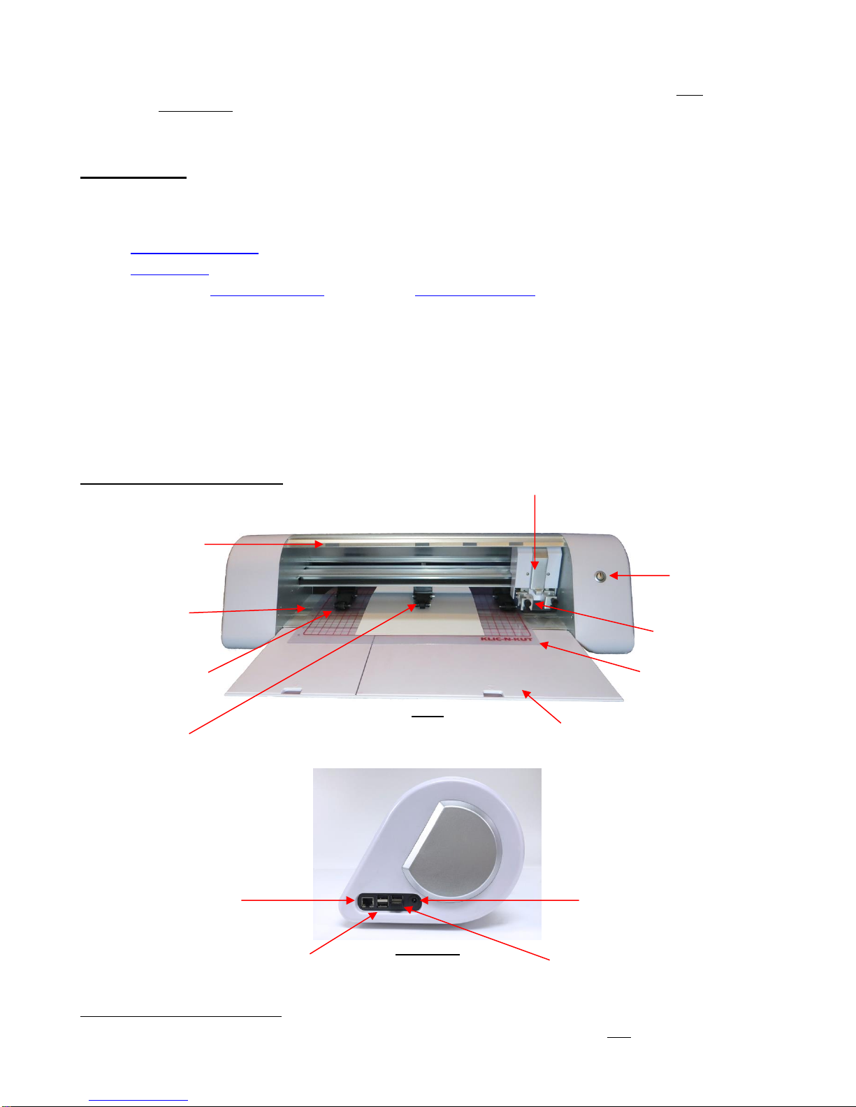
1.07 Parts of the KNK Force
Front
Right Side
2
If you were a participant in the KNK Force Kickstarter campaign, you should have received a total of 5 blades, 3 mats, 2
blade holders and an embosser.
Blade Carriage/Head
Pinch Wheels:
Total of 3
Blade Holder Seats
with Front Screws
(total of 2)
Fold-down Front Table
Gray Positioning Labels:
Total of 4
Cutting Strip
Grit Shafts (one directly
under every gray label):
Total of 4
Power Button
Cutting Mat
(Carrier Sheet)
Power Port
USB Ports:
Total of 4
Wi-Fi Adaptor
Ethernet Port

1-5
1.08 Blade Holders and Blades
• There are three kinds of blades for the KNK Force:
The 45 degree red capped blade is suited for cutting thinner materials such as paper, all cardstock
types, iron-on transfer, and vinyl.
The 60 degree blue capped blade is a much longer blade and is well-suited for cutting thicker
materials, such as gum paste, craft plastic, craft foam, and rhinestone template material. IMPORTANT!
This blade is extremely thin at the tip and can be chipped if excessive settings are applied.
The 30 degree yellow capped blade is a wide blade and is well suited for cutting fabric and felt. It has
been reported that it also works well with cardstock that has been exposed to humidity.
• Note that the red capped blade and blue capped blades have a cut back on the opposing side of the blade
(right side, in the prior photo). This reduces the blade offset value and allows for better detailed cutting of
small shapes.
• There are three blade holders sold for the Force: a red one, a blue one, and a yellow one. These three
blade holders are identical, other than the color. Thus, any color of Force blade holder can house any of the
three Force blade types.
• Owners who change materials often find it convenient to have the blade holders assigned to blade types
whose caps match the color of the holder itself. In other words, they will only use red capped blades in their
red blade holder, blue capped blades in their blue blade holder and yellow capped blades in their yellow
blade holder. Again, this is a personal choice. Any of the three blade types can be used in any of the three
Force blade holders.
1.08.1 Blade Installation3
• The blade must be carefully inserted into the blade holder. Do this over a soft surface, such as a paper
towel. It’s important to protect the fragile blade!
• Unscrew and set aside the blade holder cap at the bottom of the blade holder. Remove the protective
plastic cap (e.g. the red cap) from a blade. Keep this plastic cap so that you can cover the blade again
when you change to a different blade type.
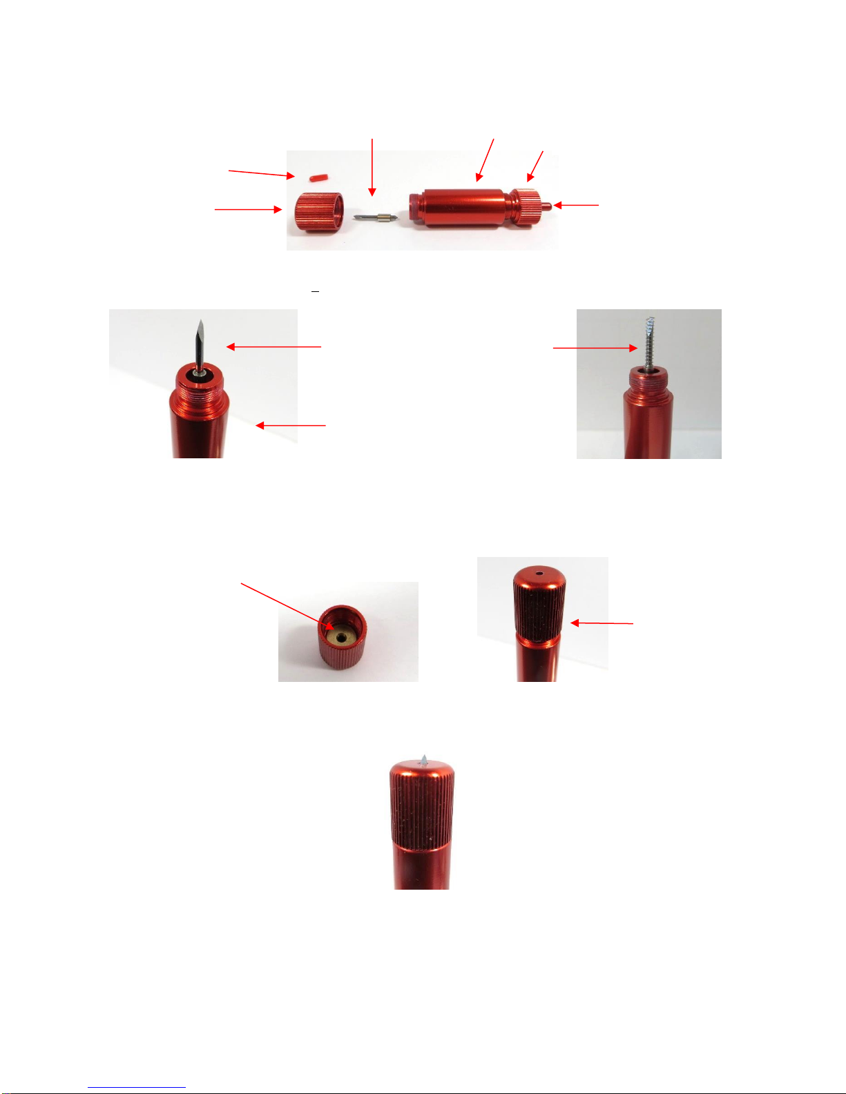
• The following photo shows how the blade will be installed relative to the blade holder cap and the main
section of the blade holder:
3
Note: At the time of writing, I only had a red blade holder available. The blade holder being shipped with the Force is a blue one. Apart
from color, there is no difference in the blade holders, thus the following procedures apply to any Force blade holder.
Red Blue Yellow
Important: Some Force blade holders have an opening that is slightly
too large and the blade may fall out during the cut. For this reason, if
your blades come with tiny springs, please slide a spring over the
blade before replacing the cap.
1-6
• Insert the blade into the main section of the blade holder, with the non-sharp end sitting inside a small hole
in the center of the blade holder. If your blades came with tiny springs, slip a spring over the blade:
• Inside the blade holder cap is an insert with a hole. Carefully place the blade holder cap over the blade so
that the blade tip is aligned with that hole:
• Begin tightening the cap. If there is any resistance, make sure the blade tip is being fed into the hole in the
cap. Screw the cap back onto the holder until it is snug.
• Because the blade is fully extended, it’s very important to exercise caution when inserting and removing the
holder from the Force. While the blade holders (with those blades extended) can easily be stored inside the
fold-down table, you should remove the blade holders before transporting your cutter. Michele Harvey came
up with a great idea for protecting the blade tips. She stores the holders in their original plastic tubes, but
has added two foam pop dots in the bottom of the tube so that the blade will be resting against that foam:
Main section of blade holder
Blade
Blade with spring
Tension Adjuster
Blade cap
Lower Cap
Blade
Shaft
Tension Scale
Hole inside of
blade holder cap
Guide the cap
over the blade
1-7
• If you don’t have these foam pop dots, there are other alternatives, such as cutting a few small squares from
craft foam or from an egg carton or even from a thick material such as felt.
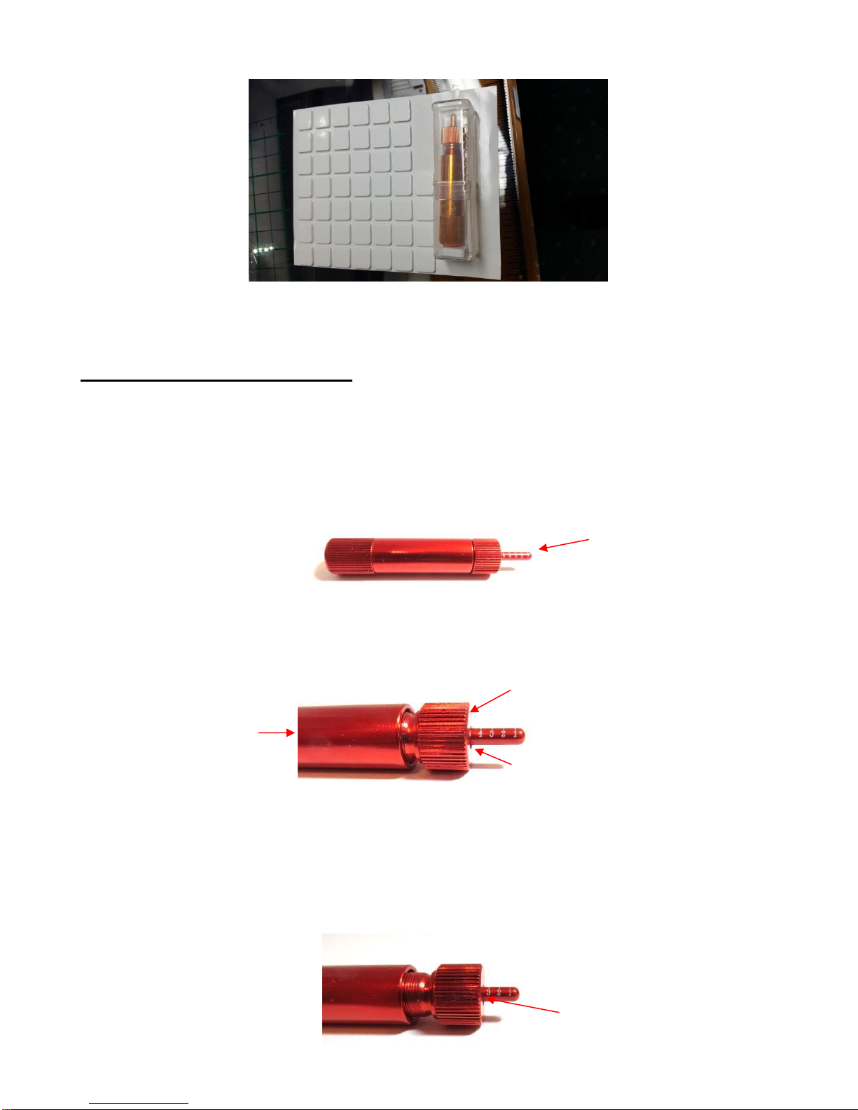
1.08.2 Setting the Blade Tension (BT)
• Inside the Force blade holder is a large spring which can be compressed or decompressed to change the
amount of tension on the blade. Lower tensions are needed for cutting thin materials while higher tensions
are better for cutting thicker dense materials.
• At the top end of the Force blade holder is the adjustable tension scale which ranges from 1 (light tension)
to 6 (high tension):
• To set the Blade Tension (BT), hold the top cap of the blade holder firmly with one hand, making sure you
can see the numbers on the tension scale. With the other hand, rotate the main part of the blade holder. As
you rotate the main section of the blade holder, the tension will change:
• When setting the BT according to a recommended value, adjust the blade holder so that the number is half-
covered, half-showing as in the prior photo where the setting is at 5. Note: Testing over the past few years
has now indicated that you will want to use a BT of ~0.5 for vinyl and paper, ~ 1 for cardstock, and 2 for
chipboard and plastic.
• There are approximately four revolutions between any two numbers. If a “half setting” is recommended,
such as 3.5, then the blade holder would be rotated about two revolutions so that the tension is
approximately halfway between 3 and 4:
Tension Scale: 1 to 6
Rotate clockwise (away
from you) to decrease BT.
Rotate counter-clockwise
(towards you) to increase
BT
.
Grip this part while rotating
main part of holder.
BT is set to at 5.
BT is set to ~3.5.

1-8
• To learn more about the importance of Blade Tension, please read Section 3.03.
1.09 Accessory Tools
The following accessories can be purchased for use with the KNK Force:
• Rotary Tool: Used for cutting thicker materials, engraving metal/wood/acrylic, and drilling holes. Refer to
Chapter 7.
• Embossing Tool: Used for scoring and embossing paper products and thin leather. Refer to Section 5.05.
• Engraving Tool: Used for scoring craft plastic and performing thin line “scratch” engraving on metal, vellum,
and acrylic. Refer to Section 5.06.
• Punch/Piercing Tool: Used for punching tiny holes in paper, vellum, and other soft thin materials. Refer to
Section 5.07.
1.10 Preparing and Caring for the Cutting Mat
Mat too sticky: Adding more adhesive to a mat:
1.10.1 Tips on Using the Cutting Mat
• Always use a mat to hold the material to be cut unless the material has its own protective backing. For
example, vinyl and iron-on transfer both come with a layer that you do not cut. Thus, this backing layer
serves as the carrier for cutting. Paper and cardstock do not have a backing, thus they must be cut on the
mat.
• IMPORTANT! A new Force mat has the best tackiness for cutting fabric and plastic. However, it is too
sticky if you are cutting paper products. This can cause difficulty in removing cut items without tearing. Place
an old but clean bath towel over the surface of the mat and press with a brayer or rolling pin. Then pull up.
Test the stickiness by pressing the palm of your hand in the middle of the mat and lifting. If the mat remains
stuck to your hand for more than a second or two, repeat until the mat can still be lifted but will release. It
should only take a few pressings to greatly reduce the stickiness, as tiny (too small to be visible) fibers from
the towel are added to the surface.
• If you have inconsistent cutting between the middle of the mat and the sides, add something such as a stack
of books or a box behind the Force.
• Do not leave the pinch wheels in a down position when the Force isn’t in use. This warps the plastic sooner,
shortening the useful life of the cutting mat. Eventually, the mat will need to be replaced.
• One of the early Force owners designed mat guides to facilitate loading the cutting mat into the same
position and stabilizing it for cutting. For more information, refer to Appendix B4.
1.10.2 Cleaning and Replenishing the Cutting Mat
• When mats begin to lose their stickiness, they can be washed:
Use a mild dishwashing detergent, warm water, and a soft brush to thoroughly clean the surface. You’re
not trying to scrub the adhesive but just wet the invisible fibers that have been deposited from your
cutting materials and get them released from the glue.
Rinse well, shake off excess water, and place sticky side down onto a bath towel.
Thoroughly dry the non-sticky side of the mat with another towel.
Pull the mat up and the sticky side should now be dry enough for immediate use. Test by making sure
the mat will stick to your hand.

1-9
• While washing with soap and water should revive the original adhesive, you can add more adhesive if
necessary:
Virtually any repositionable adhesive may be used on the cutting mat. Some of the popular choices
include: Krylon Easy Tack, Aleene’s Tack It Over and Over (diluted 1 part glue : 2 parts water), Crafter’s
Companion Stick and Spray, Zig 2 Way Glue with wide tip, Craft Smart Off ‘N On (also dilute), and
Scotch Repositionable Craft Stick. There’s another spray adhesive, Scotch Super 77, which does not
leave a sticky surface but is excellent for stabilizing paper and cardstock. Use a light coating and only
add more, if needed.
If you are cutting thicker materials, such as oil board or styrene, then you may want to experiment with a
stronger adhesive and use painter’s tape to secure the material to the mat. If you are cutting thin paper,
then you may want to experiment with a lighter adhesive.
With most repositionable adhesives, you can control the tackiness based on the amount applied. Thus,
always add a little bit at a time. As mentioned above, if you add too much, just apply a layer or two of
cotton fibers by pressing with a bath towel.
• Other reported methods for cleaning mats:
Use a plastic scraper (an old credit card will suffice) to scrape off any random material pieces remaining
on the mat after a cut.
For finer particles of paper or lint, you can use a lint roller. Tear off a sheet and then press down and pull
up across the surface of the mat to clean in sections. Baby wipes can accomplish the same task.
To completely remove adhesive from the mat, apply Goo Gone, Duck Adhesive Remover, or Avon’s Skin
So Soft Bath Oil (thank you, Joyce Wilson) across the surface. Allow a minute to soak in and then scrape
off with a sharp metal spatula. Repeat, as necessary until the mat is thoroughly clean and no longer
sticky. Wash, dry and then add any repositionable adhesive.
• One known issue with the new KNK Force mats is the red ink on the printed, non-sticky side. The ink will
begin to wear off and stick to the top of the fold-down table, as well as the cutting strip. To clean, use
Windex, Un-du, Goo Gone or even Ritz Color Remover (thank you, Julie Flanagan!). To prevent the ink
from staining the table, cover the bottom of the mat with clear Contact shelf liner, rhinestone transfer tape,
or some other thin clear adhesive sheeting.
• When necessary, the rubber wheels and the grit shafts may be cleaned with isopropyl alcohol or Un-Du.
Move the wheel away from a grit shaft, apply the cleaner to a clean lint-free rag and rub the entire wheel
and/or grit shaft until free of adhesive.
1.11 Installing the Pinch Wheels
• The pinch wheel assemblies should be pre-assembled. If the levers are not attached, follow the instructions
in Appendix B1.
• To insert the pinch rollers into the Force:
First pull the lever up so that the pinch wheel will be in the “up” position when inserted into the Force:
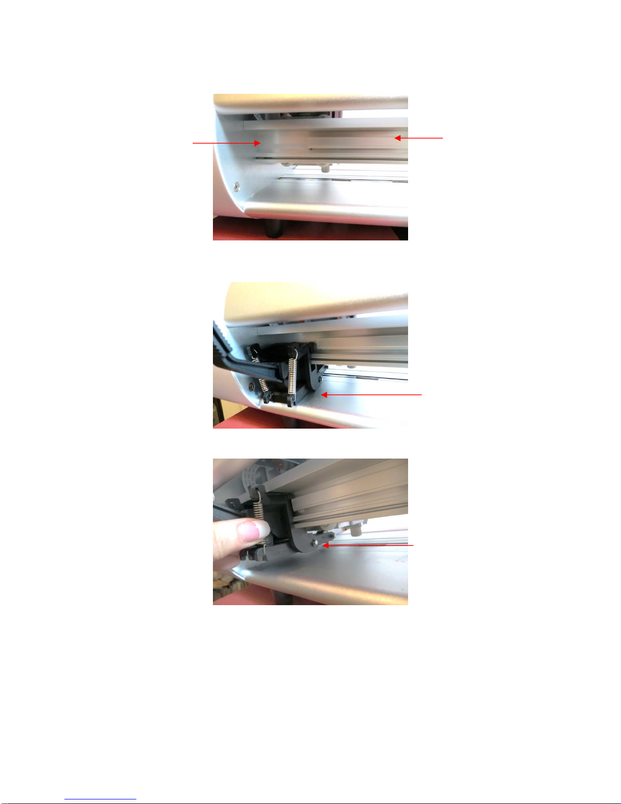
1-10
Next, turn the Force around so that you are facing the back of the cutter.
Place the pinch wheel assembly into the Force so that it’s resting on the bottom plate, on the far left side
where the gap is located.
Lift the assembly straight up and then away from you (towards the front of the cutter):
Then slide the assembly towards the right onto the bar.
Gap between inside
end gap and
horizontal railing
Horizontal railing onto
which the pinch wheel
assembly will slide
Rest assembly along the
left side as you face the
back of the Force.
Lift assembly up
and off the table

1-11
That’s it! Repeat with the other two pinch wheels.
• I personally recommend applying a small amount of WD40 to the top and bottom of the bar so that the pinch
wheels slide more easily. Do NOT spray WD 40 onto the bar directly! Instead, spray a small amount onto a
cloth or paper towel and then wipe the bar thoroughly to apply. You should now be able to more easily slide
the pinch rollers left and right. If you still have difficulty sliding, try applying a small amount of WD40 to the
parts of the pinch roller assemblies which are in direct contact with the bar.
• Note that when you get ready to use the Force, the pinch wheels will need to be aligned under the gray
rectangles so that they are positioned over the grit shafts. More about this is covered in Section 2.6.2.
1.12 Other Useful Tools and Supplies
• The following list has items you may or may not need while enjoying your Force. These are suggestions
based on ten years of collecting information from cutter owners:
Brayer or Rolling Pin: (1) to apply lint from a towel onto an overly sticky mat (2) to press materials
evenly onto a mat for cutting
Old Fluffy Bath Towel: (1) to dry a washed mat (2) to apply an invisible layer of lint onto an overly-
sticky mat
Dishwashing Soap: (1) to remove visible and invisible fibers, thus renewing the adhesive (2) to clean the
mat well before adding more adhesive
Soft Brush: (1) to gently remove waste scraps during the washing of a mat
Artist Palette Knife: (1) to gently remove cut shapes from a mat (2) to scrape off small waste pieces
from a mat
Blue Painter’s Tape: (1) to tape around the edges of thicker materials that might slip during cutting
Repositionable Adhesives: (1) to add more adhesive to a cutting mat (most any brand or type can be
used, provided it is repositionable). When using a glue-type, dilute with water in a 1:2 glue-to-water ratio
for a light tackiness or 2:3 glue-to-water ratio for a stronger tackiness.
Awl or Paper Piercer (or other sharp pointed tool): (1) to pick or lift out a test cut to verify results
Stabilizers: A stabilizer is an adhesive material that is applied to the bottom of the material you are
cutting so that cleaner cuts can be achieved. The stabilizer works in one or more of the following ways –
(1) provides firmer contact with the cutting mat (2) provides a final layer that does not need to be cut if
the stabilizer will be removed after cutting (3) prevent some slightly-elastic materials from being
stretched by the blade. Recommended stabilizers for particular materials will be listed in relevant
sections of the user manual.
• When using the KNK rotary tool, the following items are recommended:
Caliper: (1) to measure the thickness of a material. This is most likely not something you “need,” but
rather a convenience when determining the best settings based on suggestions in the table. Often you
Slide assembly onto
the bar

1-12
can find the thickness on packaging labels, but occasionally you might pick up a material and not be
sure if it’s 5 mil versus 7 mil or 1/8” versus 3/32”.
Safety Glasses: (1) to protect your eyes
Dust Mask: (1) to prevent inhalation of fine dust particles
Self-healing Mat: (1) advisable when cutting materials with the KNK rotary tool.
Blue Painter’s Tape: (1) to tape around the edges of materials that might slip during cutting

1-13
1.13 Review of Chapter 1
1.13.1 Miscellaneous Things to Note:
• The KNK Force is unlike other cutters in the hobby world. It has Z Axis control:
This changes the settings used for cutting: instead of a pressure setting, there are depth settings and
more speeds.
Multiple passes allow a blade to work its way through a material versus trying to press through the
material from the start. This is also important when using the rotary tool.
You need to use the Force blade holder (versus other brands) as it contains a large spring which offsets
the strong downward pressure. The blade holder has a Blade Tension setting: use a low number for
thinner softer materials; a higher number for thicker denser materials. Refer back to Section 1.08.2.
The blade is now fully exposed since the cut is controlled by depth settings.
• Never use extreme settings. This can result in broken blades, punctured cutting mats, and damaged
surfaces to the Force.
• Read Chapter 1, Chapter 2, and Sections 3.01-3.05 before cutting. The rest of the manual can be used as
a reference guide for specific topics of interest.
• Blade Installation Video: Refer to Section 1.08.
• A new Force mat is too sticky if you are cutting paper products. Place an old but clean bath towel over the
surface of the mat and press with a brayer or rolling pin. Then pull up. It should only take a few pressings to
greatly reduce the stickiness, as tiny (too small to be visible) fibers from the towel are added to the surface.
• The cutting mats can be washed and replenished, as needed. Refer to Section 1.10.
• Pinch Wheel Installation Videos: Refer to Section 1.11.
• If you have questions about using the Force, such as help with cutting specific materials, join one of the
support groups recommended in Section 1.04. The Force Facebook group is the most popular one.
• If you are having mechanical issues with the Force, please call KNK USA (800-268-3672) or start a support
ticket.

2-1
Chapter 2 Getting Started
2.01 What is C3?
• The KNK Force comes with the Cutter Command Center (C3) software installed on the computer inside the
cutter. This current user manual is based on C3 version 0.5.40.
• C3 is a cutting program that will open .SVG (Scalable Vector Graphics) files. Thus, for custom designing
and modifying files, you will want to use a vector program that will save or export in .SVG format. The most
common programs used to create cutting files are Sure Cuts a Lot (SCAL), Make The Cut (MTC), Inkscape,
Adobe illustrator (AI), and Corel Draw.
• There are many other programs on the market as well, such as embroidery programs and CAD programs
that can save in .SVG format. However, before purchasing any design software for use with the Force, verify
that you will be able to export in .SVG format AND that the format will open and cut from C3.
• Contact KNK USA if you need assistance selecting a new program for designing and/or testing SVG files
from other programs not listed in this manual. Additional information about .SVG files is presented in
Chapter 4 and also at this blog post by Darrel Farris: http://cutterpunk.com/svg-files-for-cutting-machines/.
• To access the C3 program, you will need to select from one of the three available connection methods in
order to complete the setup between your computer or smart device and the Force. An IP Address is
assigned by your network during this set up. Make a note of this IP Address as you will use it each time you
open the C3 software. That address is typed into whatever browser software you normally use (Firefox,
Safari, Google Chrome, etc.). At this time, both Internet Explorer and Edge have had some issues working
correctly with C3. Thus, it is recommended that an alternate browser program be used.
• You will always use this same IP Address unless the connection is changed. Once you set up the
connection on one of your devices (e.g. your computer), you can then access the Force from other devices
(e.g. smart phone, tablet, another computer) without repeating the setup procedure. Entering the same IP
Address in that device’s browser will launch C3.
• When an update to C3 is available, you will see a notification pop up near the top of the screen. You can
install this update by downloading within C3 or by first downloading and saving the update as a file on your
computer. Details on updating are provided in Section 4.03.
• IMPORTANT! Carefully and completely follow the instructions in the following sections to make sure
everything is set up properly.
2.02 Setting Up the Force
• IMPORTANT! If your Force was shipped to you prior to February 16, 2016 you will need to use the
instructions in Appendix B7.2 to set up the Force. Once that is completed, you may then return and start
reading Section 2.06.
• If you are attempting to reconnect (after having a successful connection in the past) and you are seeing
“knk_recovery” under your list of available networks, please watch this video:
• If you are attempting to switch to standalone mode after being connected from another mode, go to Section
2.03.2.
2.02.1 Terminology
Some of the early Force owners provided feedback regarding their unfamiliarity with certain terms used in the
Force setup procedures. So, a list and explanation of the terms used in this section are provided in Appendix
B7.1. These definitions were specifically written with the Force connection in mind.

2-2
2.02.2 Choosing a Connection Mode
• You have three options for connecting the Force to your computer: Standalone (Ad Hoc), Ethernet, or Wi-Fi.
Review the information in the following table to understand the differences between these options:
Option Stand-Alone (Ad Hoc) Ethernet Wireless (Wi-Fi)
Description
Communication is directly
between the computer (or
smart device) and the Force
The Force is connected to a
network router using an
Ethernet cable
The Force is wirelessly
connected to a network router
Requirements
(1) Wi-Fi adaptor (preinstalled
on the Force)
(1) Ethernet cable (included)
(2) Network router
(1) Ethernet cable (included
and only needed during setup)
(2) Wireless network router
(3) Wi-Fi adaptor (preinstalled
on the Force)
Pros
Easiest to install; can be
setup anywhere as no router
is required
Most reliable connection;
Fastest communication
Force can be located
anywhere within range of
router
Cons
Computer is now connected
to the Force, thus no wireless
access to the Internet or to
other wireless devices.
Force is connected to router
with a 6 ft Ethernet cable
unless a longer cable is
purchased
Requires more steps for set
up
• Note that implementing any of these options does not preclude you from changing to another one, as
needed.
• A fourth option is available whereby you can connect, via Ethernet, from the Force to your computer, instead
of to your router. Please refer to Appendix B8.
2.02.3 Connecting and Launching C3
(1) Place the Force on a flat sturdy surface located according to the mode you plan to use:
Ethernet: Place your Force within six feet of your router. Connect the Force to an available port on the
router using the included Ethernet cable. Do NOT remove the Wi-Fi Adaptor. It needs to remain in
place, even after establishing an Ethernet connection.
Wi-Fi: Place your Force within six feet of your router. Connect the Force to an available port on the
router using the included Ethernet cable. Once the Wi-Fi setup is complete, the Ethernet cable can be
removed and the Force relocated within range of your router.
Ad Hoc: Place the Force within ~100 feet of your computer or smart device.
(2) IMPORTANT! Follow this sequence for connecting the AC/DC adaptor and power cable:
Connect the AC/DC adaptor to the right side of the Force.
Plug the power cord into the AC/DC adaptor.
Plug the other end of the power cable into the wall socket or power strip.
(3) To turn on the Force, press the power button on the front. The power light will come on and the cutter will
initialize (carriage will move to the right side of the cutter). You will notice a series of quick flashing lights
inside the Force, followed by a series of slower flashing blue lights. The computer software is being loaded
and this will take about 90 – 120 seconds. Then the light will switch to solid white and will no longer flash.
IMPORTANT: Follow Step 2 below exactly as instructed
before turning on your Force for the first time.
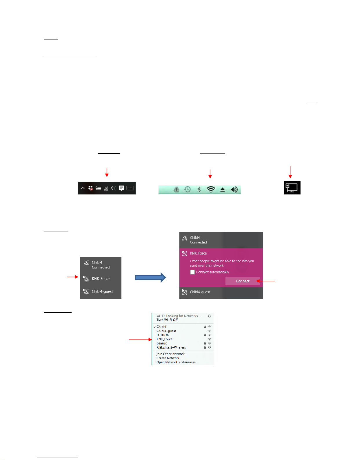
2-3
Note: If your Force never reaches the steady white light state, please refer to the first question in Appendix
A1.
(3) To turn off the Force, hold the Power button until you hear two beeps. Then the light will flash ~ ten times
before the machine powers off. (For now, there’s no reason to turn it off. This is mentioned only for future
reference.)
(4) Before starting, close all unnecessary applications on your computer or smart device. It is also
recommended that you temporarily disable your virus protection software and your firewall.
(5) The following steps were written for a Windows 10 operating system and for a Mac 10.9.4 operating system.
The steps should be virtually identical for other versions. Note: If you are choosing the Ethernet mode and
you know how to access your router’s admin panel, you can skip Steps 7 and 8. You’ll need to know how to
find your router’s client list to find what IP has been assigned to your KNK Force. With the Force in steady
light mode and the cable connected to your router, you should be able to use that IP address in the address
bar of your browser and launch C3 and proceed to Step 9.
(6) With the Force in steady light mode, locate and launch the network icon for your computer:
(7) You will see KNK_Force as a device to which you can connect. Click on it.
On a PC:
On a Mac:
(8) Once connected, your default web browser should open up and C3 (Cutter Command Center) will be
displayed (note- your display may vary slightly):
Click on the Network icon.
(usually in lower right corner)
On a PC:
Click on the Network icon.
(usually in upper right corner)
On a Mac:
Click here:
Then click on
Connect
Click on KNK_Force
If you are connected via
Ethernet, your network icon
may look like this.

2-4
• If your web browser does not come up automatically, open it and enter 10.0.0.1 into the address bar in your
browser. You should now have access to C3 and will see the previous display in Step 9. Note: 10.0.0.1 will
always be the default IP address for the KNK Force when in standalone mode.
• If you are unable to connect to the KNK Force, make sure there are no other automatic network connections
interfering. As mentioned previously, you may need to disconnect from your existing network and disable
your virus protection program. Also, some models of wireless printers may need to be turned off.
• Proceed to one of the following sections for the connection mode you’ve chosen.
2.03 Standalone (Ad Hoc) Connection
2.03.1 First Time Standalone Mode
• After completing the steps in the prior Section 2.02.3, you are now ready to begin using your Force and can
proceed to Section 2.06. However, please read the rest of this section as it contains information you’ll need
at some point.
• While in standalone mode with a wireless computer, you will no longer be connected to your regular network
unless you are connected to it via Ethernet. Thus, you won’t have access to the Internet. On the other hand,
if your computer is connected via Ethernet to a router, then you should have access to the Internet using
that connection.
• In order to do future C3 updates, you will need to connect the Force either by Ethernet or by Wi-Fi or
download the update as an installable file. Refer to Section 4.03.3.
2.03.2 Switching to Standalone Mode after Being in Another Mode
For a video: go to https://cutterpunk.com/knk-support/knk-force/, go to Page 2, click on a video titled KNK ForceSwith from LAN to Standalone Mode.
• Power down the Force. If you have a network cable plugged into the Force, remove it.
• Power the Force on and wait for the steady light. Note which port is being used for the Wi-Fi adaptor. Then
remove it and wait for the lights to turn red.

2-5
• Put the Wi-Fi adapter back into the same slot and wait for the lights to turn green.
• Go to your wireless network connections on your computer:
Find the knk_force_recovery connection and click on it. (Note that it may take up to 90 seconds or so
for this connection to appear in the menu.)
A window should appear displaying C3’s setup screen. If not, open a non-Microsoft web browser and
navigate to http://10.0.0.1. Do not change anything in this window.
Click on Try these settings.
• Go back to your wireless network connections on your computer:
Wait, again, for the knk_force_recovery to be listed. Do not select knk_force, if that option appears.
If you had a web page open, it will eventually display a Server Error (page not found).
When knk_force_recovery appears, click on it (connect to it).
After connecting, a window should display stating Connection Succeeded and display an assigned IP
address of 10.0.0.1. Click the Save these settings and continue button.
• A window will display instructing you to connect to your regular Wi-Fi and click the link to http://10.0.0.1. Do
not do this.
• Instead, wait ~60 seconds for the knk_force wireless network to appear. If it does not appear, reboot your
Force and it should appear after the startup sequence is complete and your Force displays a white light.
• After connecting to the knk_force wireless network, open your web browser and go to http://10.0.0.1. C3
should now display.
• Note: In a setting with other Force owners (such as a KNK Retreat), communicaton conflicts will occur as
owners attempt to set up standalone mode. One owner, at a time, will need to turn on their computer and
Force, complete the steps above, and then rename their wireless network before the next person begins. To
rename the wireless network, change the values in Network hostname field (i.e. force-newname) and the
Wireless network name (ESSID) field (i.e. newname_force).
2.04 Ethernet Connection
• Once C3 has loaded, click on the Status tab at the top of the screen. Scroll down to Wired (Ethernet)
networking status and take note of the IP address. This is the address you’ll use to connect to C3.
• With the Ethernet connection, you should be able to connect to your Force using other devices connected to
your router, such as another computer, smart phone, or tablet. You only need to type in the IP address into
a browser window on that device.
• IMPORTANT! At this time, the Force needs the Wi-Fi adaptor installed, even when connecting via Ethernet.
Thus, do not remove the adaptor.
• To update to the latest version of C3, refer to Section 4.03.
• You are now ready to begin using C3. Please go to Section 2.06.
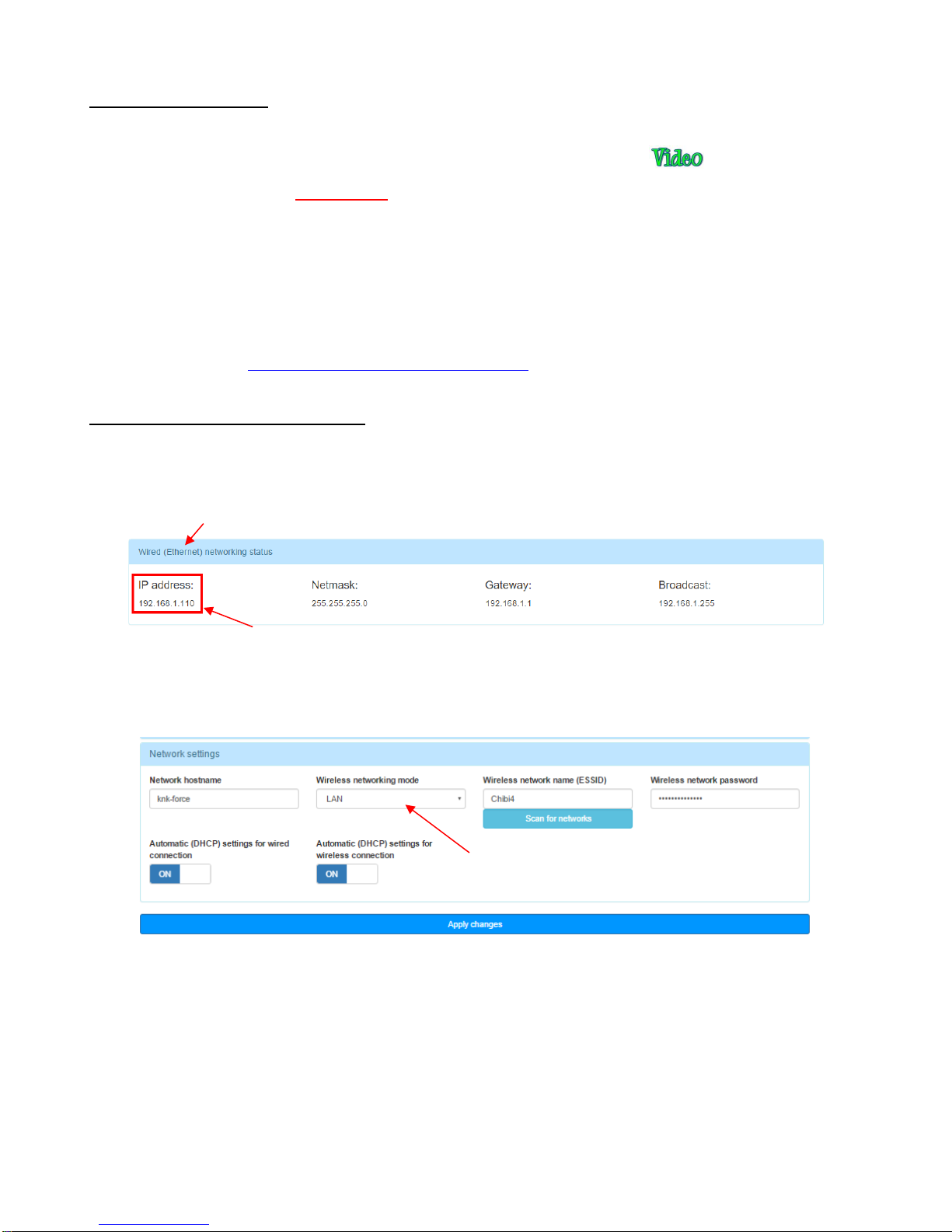
2-6
2.05 Wi-Fi Connection
• If you are attempting to reconnect (after having a successful connection in the past) and you are seeing
“knk_recovery” under your list of available networks, please watch this video:
• Please read the following IMPORTANT info carefully. It contains the current requirements for the Force to
successfully connect to your router:
The wireless network must be password protected. You will need to know the name of your network and
this password for the setup process.
If your network is set up to be invisible, then you will probably need to select “other network” in
dropdown menus and type it in.
Some owners of a modem/router combined device have issues getting connected. If you cannot get the
following instructions to work, please contact KNK USA for assistance. You can start a support ticket
using this link: http://knkusa.com/support-ticket-request/ or call 800-268-3672.
2.05.1 Obtaining the Wi-Fi IP Address
(1) Click on the Status tab at the top of the screen. Scroll down to Wired (Ethernet) network status and
take note of the IP address. You will need to use this address later, so you might want to write it down:
(2) Click on the Settings tab at the top of the screen and click on Network Settings. Click the right arrow in the
box under Wireless networking mode and change it from Standalone to LAN.
(3) Click on Scan for networks and select your network name from the available choices in the menu. Then
enter the wireless network password and click on Apply changes:
Select LAN here
Go to the Wired (Ethernet) section
Write down this IP address
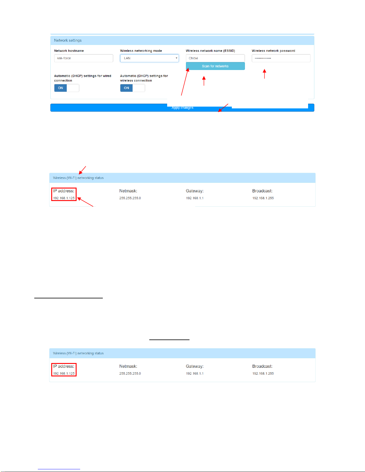
2-7
(4) Enter the Wired (Ethernet) IP address into the address bar of your browser and relaunch C3.
(5) Click on the Status tab at the top of the screen. Scroll down to Wireless (Wi-Fi) network status and take
note of the IP address. This is the address you’ll use when connecting to the Force using your wireless
computer or smart device:
(6) The Force can now be accessed wirelessly. Disconnect the Ethernet cable and type in the IP Address from
Step 5 or power down the Force, disconnect the Ethernet cable, and move the Force to your desired
location within range of your network router.
• With the Wi-Fi connection, you should be able to connect using other devices connected to your router,
such as another computer, smart phone, or tablet. You only need to type in the IP address into a browser
window on that device.
• To update to the latest version of C3, refer to Section 4.03.
2.05.2 Setting a Static IP
The following procedure is recommended if your network is setup as a DHCP network (which is the most
popular type of home network). Setting a static IP for DHCP networks can eliminate communication issues. The
IP address will not change and the connection tends to be a little quicker.
(1) Click on the Status tab and write down all four settings in the Wireless(Wi-Fi) network Status section:
(2) Click on the Settings tab and click on Network settings. Turn off Automatic (DHCP) settings for wireless
connection:
1. Click here.
2. Select your network.
4. Click on Apply changes
3. Enter your network
password
Write down this IP address
Go to the Wireless (Wi-Fi) section
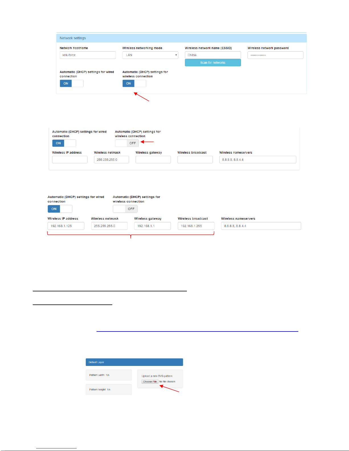
2-8
(3) This will expand that section:
(4) In the expanded section, enter the Wireless IP address, Wireless netmask, Wireless gateway and
Wireless broadcast noted in Step 1:
(5) Once complete, click on Apply changes. Your KNK Force will now remain on the IP address that was
originally assigned by your router.
2.06 Setup for Communication Testing and Drawing
2.06.1 Selecting a Test File
• You will need an .SVG file for testing. You can use the existing file that is already loaded when you first
launched C3. Alternatively, for convenience, a zip file of basic shapes in .SVG format is available to
download from here: http://www.iloveknk.com/FreeFiles/SVG/Force-Testing-and-Calibration-Files.zip.
• After saving this file to your computer, extract the files, noting where the files are being saved.
• To open the file, click the Choose File button on the right side:
• Navigate to the folder containing the Basic Shapes and select one. Then click on Open.
Click on Choose File
Click here to turn off
Should now be OFF
Enter settings noted in Step 1
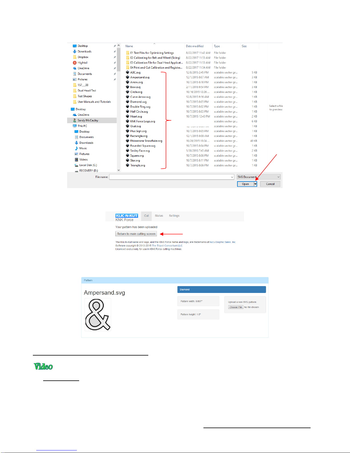
2-9
• A new screen will indicate the file is being read. Then a button will appear to return you to the main screen
again:
• The imported shape will now appear as a thumbnail image on the left side of the screen. The dimensions of
the imported shape are also shown:
2.06.2 Preparing the Force for Drawing
• IMPORTANT! Make sure you have read Section 1.10 before using the included Force cutting mat. It is
extremely sticky and you will need to reduce some of the tackiness before use.
• Press a sheet of paper onto the mat, roughly centered left-to-right. Because the pinch wheels press so
tightly on the cutting mat, inconsistent drawing and cutting can occur if the paper is under or immediately
next to a pinch wheel.
• Raise the pinch wheel levers in the back and slide the mat into the cutter, aligning the horizontal lines on the
mat’s grid with horizontal grooves on the Force under the mat. Make sure the pinch wheels are aligned
Click here after file is uploaded
Select any file.
Click on Open.
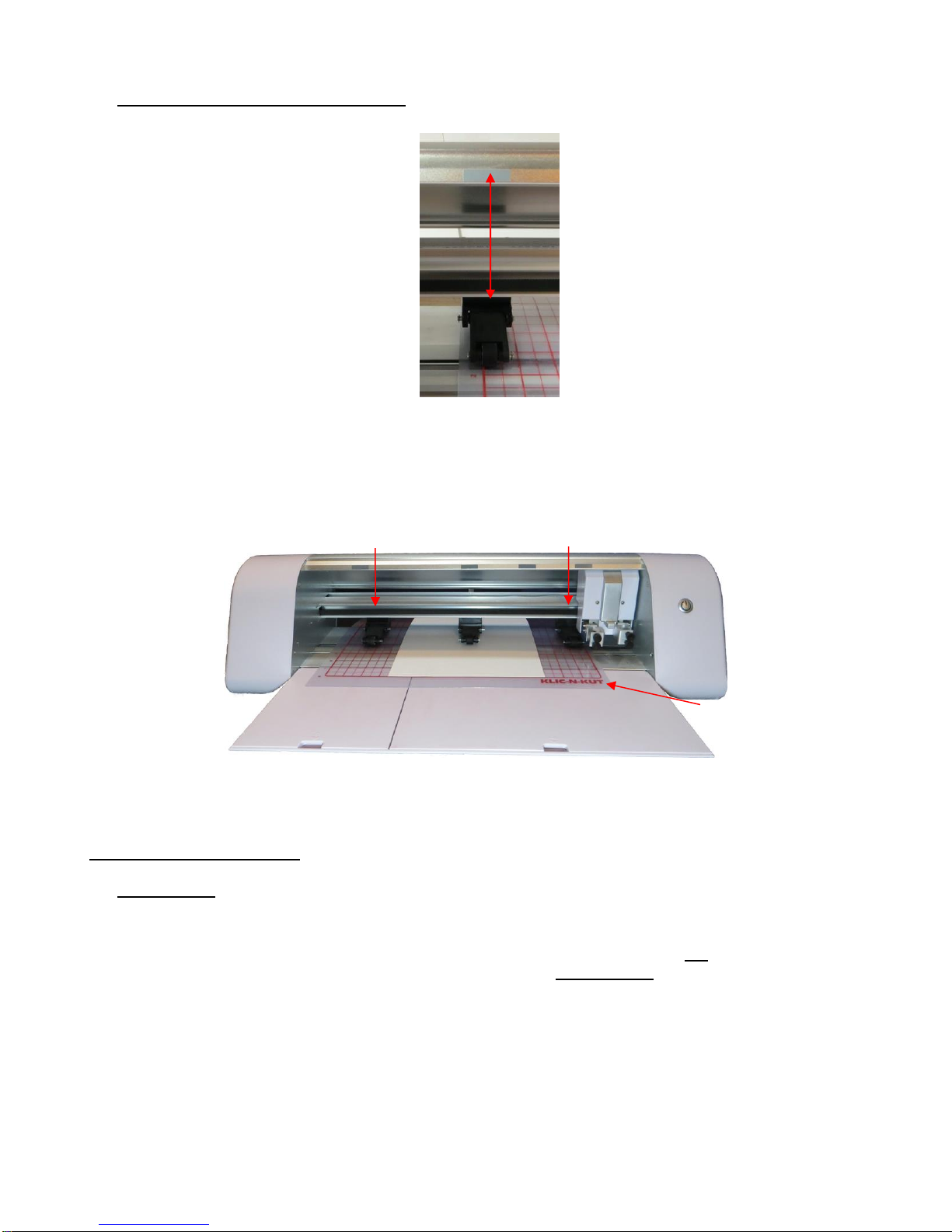
2-10
under the gray rectangles on the cutter. This places the wheels directly over the grit shafts under the
mat. Without proper alignment, the cutting mat is subject to skewing.
• The pinch wheels can be slid left and right, as needed. Once they are positioned under rectangles,
drop the levers. Note that only two wheels need to be used for this testing or when cutting most
materials. You can leave the middle pinch wheel up, if desired, as long as the far left and far right
wheels are both gripping the mat:
• Make sure the test pen will write by scribbling on scrap paper. At this time do NOT insert the pen into the
Force.
2.06.3 Setting the Z Origin
• IMPORTANT! The Z Origin sets a baseline location from which you then set depths for cutting, engraving,
drawing, etc. It should be done any time you change out a blade holder or tool or, in some cases, the
material. Follow the directions carefully!
• This origin is set with the tip of the blade (or other tool) touching the top of the mat OR touching the top of
the material when the blade holder seat is in the down position. IMPORTANT! To avoid damage to a tool,
do not insert the test pen or the blade holder into the Force until instructed!
• For test drawing on paper, the Z origin will be set on top of the material. But there will be applications in
which the origin will be set with the tool tip on the mat instead. Use the following guidelines for whether to
set the origin on top of the cutting mat or on top of the material. For more information about this topic, refer
to Appendix B2.
Always use the far left and far right pinch
wheels with the cutting mat.
Wheels should be centered
under gray rectangles.
Note the location of the
mat relative to the Force.
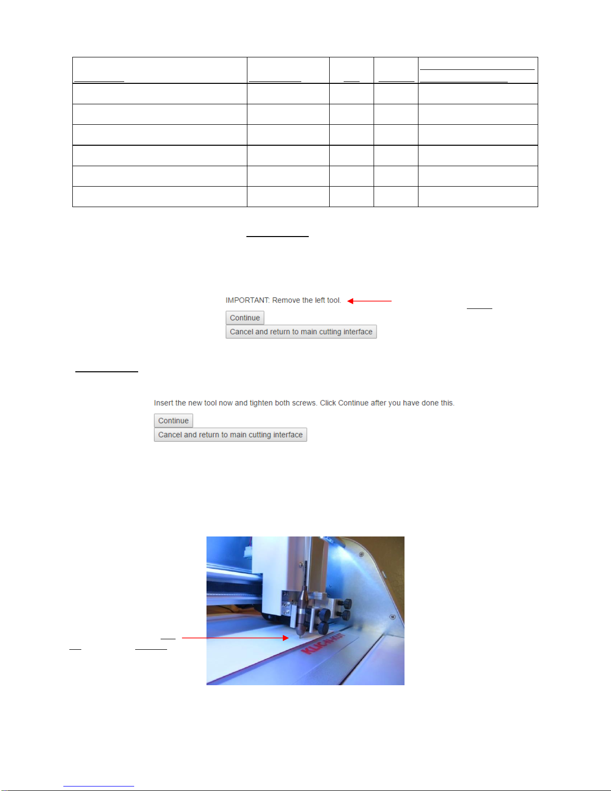
2-11
Application Tool in Use Mat Material
Must Reset Z Origin When
Changing Materials?
Cutting a material on the mat Blade holder ✓ No
Cutting a material on the mat Rotary Tool ✓ Yes
Engraving, Embossing, Drawing Accessory Tools ✓ Yes
Piercing a material on the mat Pierce/Punch Tool ✓ No
Engraving Rotary Tool ✓ Yes
Cutting backed materials with no mat Blade holder ✓ Yes
• You’re now ready to load the test pen. IMPORTANT! Always use the left side when only using one tool.
Regardless of single or dual tool use, the left side is always the reference base for the XY origin.
• At the bottom of the C3 screen, click on Replace Left Tool. The motor for the head will be turned on and
the head will move to the left. The following instruction will appear:
• IMPORTANT! If you still had a blade holder or other tool installed on the left side, you would remove it.
Then click on Continue. The left side blade holder seat will drop and the next instruction appears:
• Before inserting the test pen into the Force, scribble with it to make sure the ink is flowing. Then insert the
test pen into the Force. Note: Since you want to set the Z Origin with the pen touching the material, you may
need to temporarily place a sheet of paper over the mat where the blade holder seat is now located.
• Insert the pen so that it is freely resting with the nib of the pen on the paper. You may need to loosen the
screws a bit on the left seat so that the pen can be inserted. Then tighten both screws:
• Note that if you were using the blade holder, in which case the Z origin would be set over the mat, then you
might need to slide the mat towards the back so that the blade holder seat is over the front margin of the
cutting mat. Then insert the blade holder and tighten the screws:
If anything is inserted on the left
side, remove it before pressing
Continue.
Z Origin is set with the pen
nib touching the material.
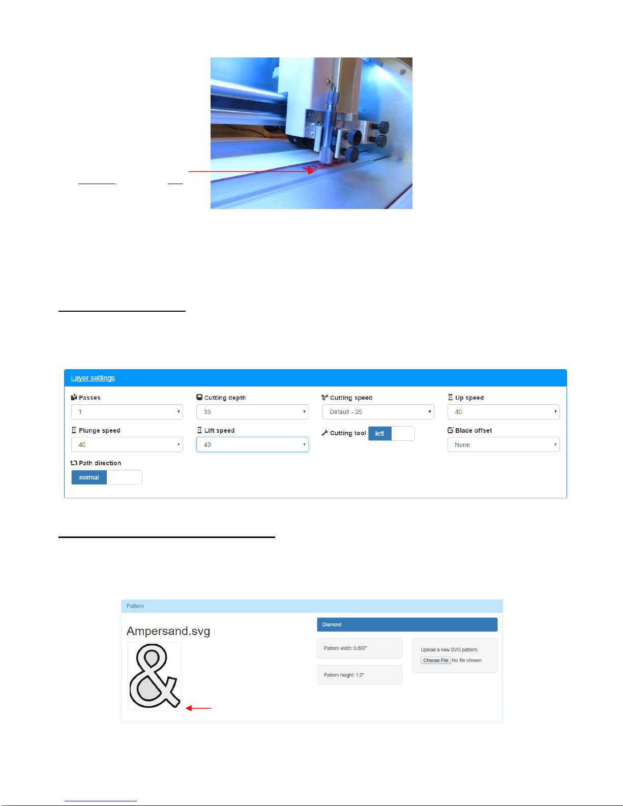
2-12
• Alternatively, other parts of the mat can be used. It’s a personal choice. Just remember to drop the pinch
wheels before tightening the screws so that the mat will be as flat as possible.
• Click on Continue and the head will now move back to the far-right side, the cooling fan will shut off, and
the main screen of C3 will appear.
2.06.4 Entering Settings
• Below the Pattern section in the main screen of C3, is the Layer Section. This is where the settings are
entered for drawing, cutting, engraving, etc. For now, just change the settings so that they match the screen
shot below. Details regarding each setting are covered in Section 3.02.
2.06.5 Setting the XY Origin and Drawing
• Now that the file is imported, the test pen installed, the Z Origin set, and the settings entered, the Force is
ready to carry out the test. The last step before cutting is setting the XY origin, which approximately
corresponds to the lower right corner of the bounding box around the thumbnail image you see in C3:
• Click on the following button below the Layer Settings:
Z Origin is set with the
blade tip touching the mat.
XY Origin
 Loading...