


!
Contents
!"#$%#$&
1.!Quick-start!!!.................................................................................................................................................................................!3!
2.! Introduction! !...............................................................................................................................................................................! 6!
3.! EC ! Declaration! of!conformity!!!...................................................................................................................................................!8!
4.!Getting!started-safety!check!!!......................................................................................................................................................!9!
5.!Behavior!in!road! traffic! !...........................................................................................................................................................!10!
6.!Propulsion!system!of!Klever!Mobility-Biactron!!!......................................................................................................................!11!
!!!!6.1! Sensors! and! fu n ctio n! !! .................................................................................................................................................! 12!
!!!!6.2! Levels! of! support! !! .........................................................................................................................................................! 13!
!!!!6.3!Display!!!............................................................................................................................................................................14!
!!!!!!!!!!6.3.1!Function!of!each!button………………....................................................................................................................!15!
!!!!!!!!!!6.3.2! Assembly! and! disassembly! of! the! Display! !.....................................................................................................21!
!
!!!!6.4!Battery! !!...........................................................................................................................................................................!22!
!!!!!!!!!!6.4.1!Charging!of!the! battery!!!..................................................................................................................................!25!
!!!!!!!!!!6.4.2!Range!!!..............................................................................................................................................................!27!
!!!!!!!!!!6.4.3!Disassembly!and! assembly!of!the! battery! !.....................................................................................................! 28!
!!!!!!!!!!6.4.4!Transport! of!the!battery! !!................................................................................................................................! 2 9 !
!!!!6.5!Troubleshooting!!!............................................................................................................................................................! 29!
7.!The!Bicycle!!...............................................................................................................................................................................! 30!
!!!!7.1!Saddle!and!handlebar!adjustment!!! ................................................................................................................................! 30 !
!!!!7.2!Headset!!!..........................................................................................................................................................................!32!
!!!!7.3! Suspension! fork! !! ...........................................................................................................................................................! 34!
!!!!7.4! Brakes! !.............................................................................................................................................................................! 34!
!!!!7.5!Drive!and! gearshift!!! .......................................................................................................................................................!36!
!!!!7.6! Lighting! !........................................................................................................................................................................! 38!
!!!!7.7!Wheels!and!tires!!.............................................................................................................................................................!39!
!!!!7.8!Luggage!carriers!!!.............................................................................................................................................................!4 3!
!!!!7.9!Child!seat!!! .......................................................................................................................................................................!4 4 !
!!!!7.10!Head!tube!threads!.........................................................................................................................................................!44
!
!!!!7.11!Locks!and! anti-the ft! system! !!.......................................................................................................................................! 45!
!!!!7.12!Accessories!!!..................................................................................................................................................................! 46! ! ! ! !
8.!Transport! of! the! bike!!!..............................................................................................................................................................!47!
9.! Maintenance,! care! and! storage! !! ................................................................................................................................................!
48
!
10.! Disposal! !! .................................................................................................................................................................................! 49!
11.!Technical! Data!!........................................................................................................................................................................!5 1!
12.!Liability! for! material! defects! and! warranty! !! ........................................................................................................................! 54!
13.! In te n d e d! use! !! .......................................................................................................................................................................! 56!
14.!Wear.........................................................................................................................................................................................! 5 7!
15.!Legal!requiremen ts! for! participation!in!traffic!!! ....................................................................................................................! 58!
16.!Regular!inspections! –! inspection! plan! !! .................................................................................................................................! 59!
17.!FAQs..........................................................................................................................................................................................!59 !
18.!Bicycle!passport! !! ....................................................................................................................................................................! 61!
19.! Inspection! plan!!....................................................................................................................................................................! 62!
20.! Imprint!! ...................................................................................................................................................................................! 63!
cover:+S25+(image+1)
!
QUICKSTART
'()*+,-./&$01$
2%01)-+&$"3%14!
On the first sides of this comprehensive instruction manual you will find
this Quick start guide, where you can get a quick overview of the main
features of the Pedelec.
For further information please read the additional instructions on the following
pages.
There you will find all the important technical issues and details and further
relevant information. Should you have any further questions, please ask one of
our authorized dealer or contact our technical hotline, whose contact details
are at the end of the manual.
Enjoy your Pedelec and we wish you a lot of fun
Your team of Klever Mobility.
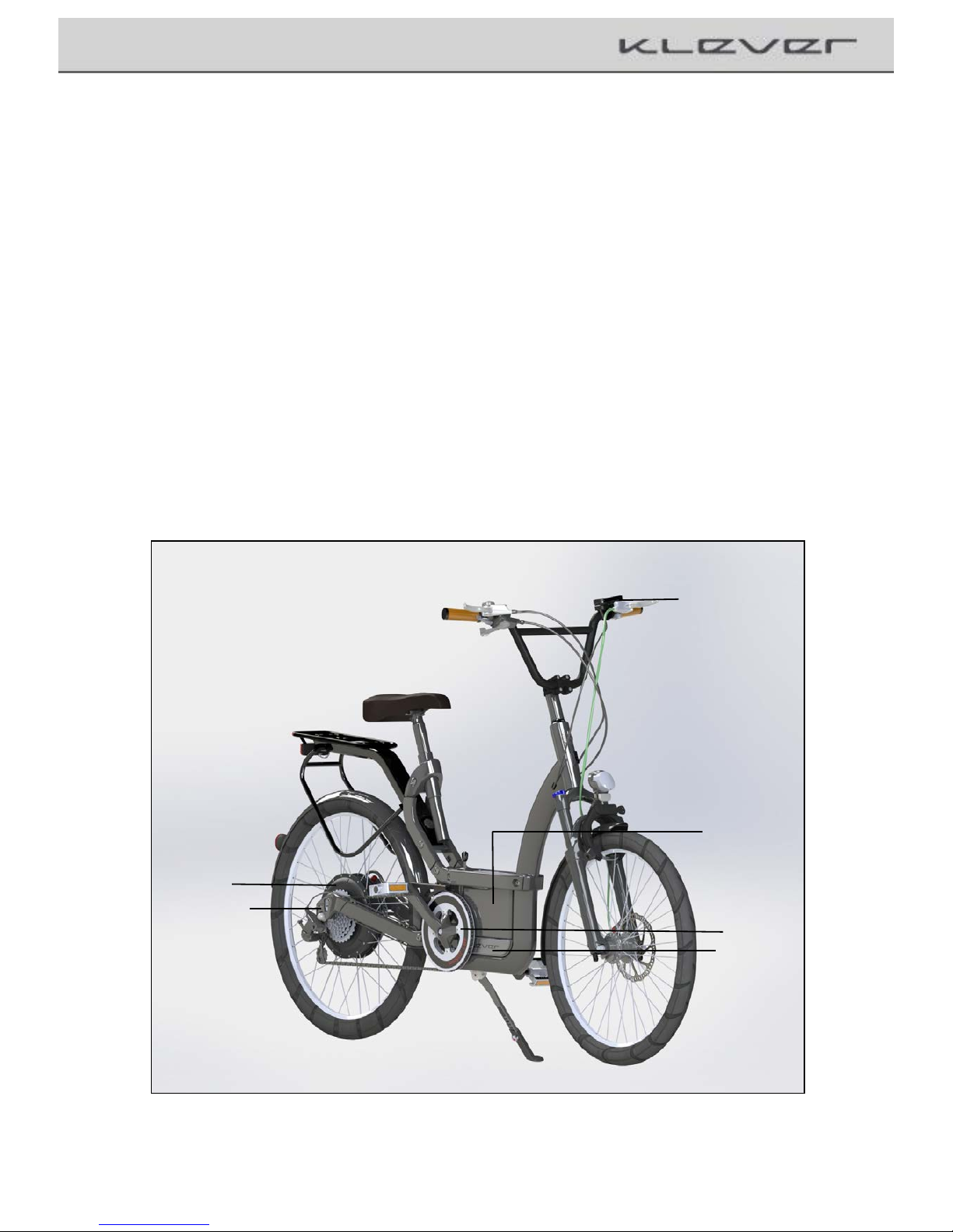
!"#$1"5)6#,$7)
2,&8509)
:0$$%19
;"$"1/
) !"#$1"55%1
;"$"1
<"1=+%)>%#&"1
)))?%@05/
>%#&"1)
Image+2+complete +bik e +m a r kin g :+major+parts+of+the+electric+drive+
3

!
0 bar
Display lights up
UL (Ultra Low)
No support;
system is activated
1 bar
L (Low)
Low support
2 bar
M (Medium)
Medium support
3 bar
H (High)
High support
Additional press of the Walk / boost button (button on the display
holder, boost function works whenever you pedaling and can be
pressed at any stage)
T (Ultra High)
Strongest support
Press the Walk / Boost button when stopped
< 6 km/h
starting and pushing aid
QUICKSTART
>%-+1,$9)-A%-.B)
Before starting the bike please always check the operation of the
brakes and the air pressure in the tires.
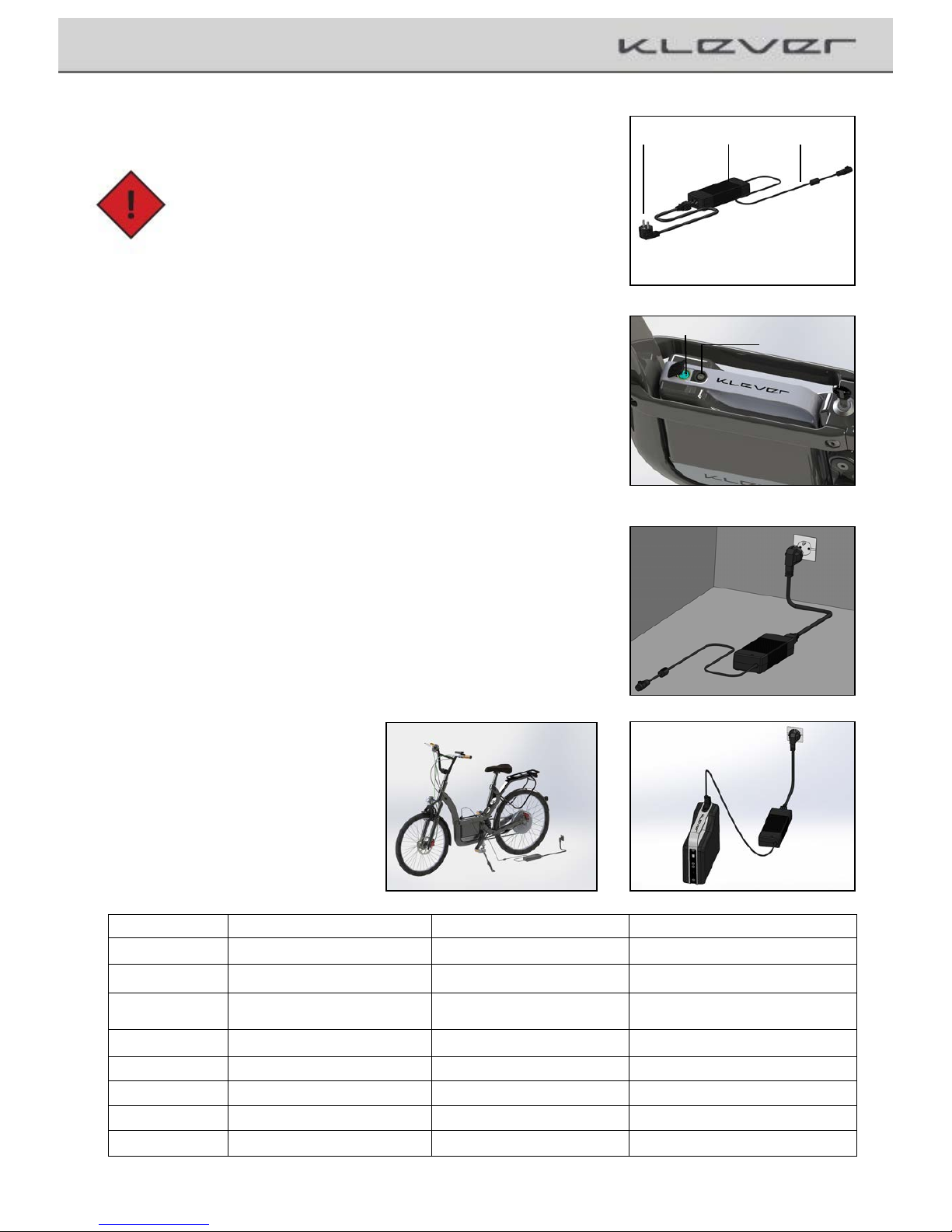
C0+#-A)"D)$A%)%5%-$1,-)@1,E%
Image+3
To start the propulsion system the display must be mounted in the
holder. There are two ways to activate the system:
'( ?1%&&)0#@)A"5@)D"1)')&%-"#@4!the start button (Image 3) – the
system runs for 3 sec through a systems check - now the
system is activated.
Or
F( G"+)&$01$)8%@05,#H)and thus the system will wake up
automatically. After 3 sec. of system check, the electrical drive
will support you. If the
bike is powered off by press power
button (image3), then the automatic start mechanism will
function with 30 sec delay after powered off.!This is for the
user who wants to ride the bike under power off mode without
any assistance.
Use the + (top left) and - (bottom left) buttons to select the desired
level of support. The support level is indicated by the bright beams
on the right side of the letters H, M and L on the display.
4
The starting and pushing aid (max: 6 km/h) can activate whenever not pedaling and speed below 6 km/h.
To activate this support, press the Walk / Boost button.
To protect battery, when charging level is below 10%, maximum support level automatically limits to M (Medium), and L (low)
when charging level below 5%, UL (Ultra low) when below 2%.
!
QUICKSTART
!A01H,#H)$A%)I0$$%19B
!0+$,"#J)<A%)I0$$%19)&A"+5@)"#59)I%)-A01H%@)K,$A)$A%)
0881"81,0$%4)&+885,%@)-A01H%1()
The battery can be charged on (image 7a) and off (image 7b) bike
(for removal the battery see Chapter 6.4.3.)
Connect the charger with the power cable and the power plug to
the wall socket. The LED on the charger shows constant red light.
The charger is ready for use (image 6)
Connect the charger plug from the charger to the charging
socket on the battery (image 5+6+7 a+b)
The charging process starts automatically. Once the LED on the
charger constantly lit green the operation is complete and the
battery is charged. First pull the plug now, and second, remove
the charger plug from the battery charger.
Power!Cable!
! Charger
Power!Plug!
Image+4
Charging!Socket!
LED
Image+5
Image+6
Image+7a
Image 7b
Charging time of an empty battery takes about four hours (0-96%) (0-100%= 6 hours).! ! ! ! ! ! ! ! ! ! ! ! ! ! ! ! ! ! ! ! ! ! ! ! ! ! ! ! ! ! ! ! ! ! ! ! ! ! ! ! ! ! ! ! ! ! ! ! ! ! !
Charging status
Charging Indicator (LED) Charger
Charging Indicator (LED) Battery
Remark
Flashing red
error
check connections
Steady red
Charger is ready
0%
Flashing yellow
Flashing red
Capacity very low; charging starts,
Normal charging
<35%
Steady yellow
Flashing red
Normal charging
35 – 75%
Steady yellow
Flashing yellow
Normal charging
75 – 90%
Steady yellow
Flashing green
Normal charging
>90%
Flashing green
Flashing green
Final Charging
100%
Steady green
no LED
Fully charged
5
!
Introduction
F()L#$1"@+-$,"#
!"#H10$+50$,"#&)
With the purchase of a Pedelec of Klever Mobility You have made
the right purchase decision and got a high quality product with what
you will have much pleasure in everyday life.
Technically and functionally up to date, it is carefully manufactured
using the highest quality materials and components. An excellent
design and excellent value for money distinguishes this bike.
In order to have permanently unclouded driving pleasure with the
new product, we would like you to read this manual carefully.
Everything you need to know in terms of technical specifications,
operation, maintenance and care we have in this booklet carefully
compiled for your information.
Please note the additional information in the instructions supplied
with the components.
?09)801$,-+501)0$$%#$,"#)$")$A%)I"5@%@)&%-$,"#&)01%)0@@,$,"#0559)
301.%@)K,$A)M!0+$,"#M()<A%)3"&$),38"1$0#$),#D"130$,"#),&)0H0,#)
&+3301,N%@)$A0$)&A"+5@)I%)"I&%1E%@)$")0E",@)8"&&,I5%)0--,@%#$&)
0#@)@0#H%1)$")9"+1)5,D%)0#@)5,3I()
:"5@)&%-$,"#&)301.%@)K,$A)$A,&)&93I"5)-"#$0,#),#D"130$,"#)0I"+$)
$A,&)I,.%)0#@),$&)0--%&&"1,%&)0#@),$&)A0#@5,#H4)0D$%1)KA,-A),$)&A"+5@)
I%)0H0,#)$")A,HA5,HA$()
O"1.)@%&-1,I%@)$A0$)I9)$A,&)&,H#)01%4)&A"+5@)I%)8%1D"13%@)I9)0)
@%05%1()<A%9)1%=+,1%)0)5"$)"D)%P8%1,%#-%)0#@)&8%-,05)$""5&()
Furthermore, if you need any further information or advice, please
contact our technical hotline at ++49 (0)223-4933420 (Monday Friday from 8-17 clock), or contact an authorized retailer.
6

!
Introduction
The latest available information on our products and other technical
information and videos can be found on our website:
www.klever-mobility.com.
Your bike is equipped by the StVZO (German Road Traffic Licensing
Regulations), and you can use it safely on public roads. It features a
bright-sounding bell, a complete lighting system with official marks
on the headlight, tail light and pedal reflectors and two independently
functioning brakes at the front and rear wheels.
The additional electric drive is limited to max. 25 km / h, and thus complies
with the statutory requirements for a bicycle.
Due to the fact, the support is limited to max. 25 km/h, you do not need
driving license or an insurance.
Moreover, it is not mandatory to wear a helmet, even though we strongly
recommend you to wear one for your own safety.
We wish you a lot of fun and safe ridings at all times
Your Team of Klever Mobility
7

!
EC+Declaration+of+conformity+
Q()R!)2%-5010$,"#)"D)!"#D"13,$9)!R
<A%);0#+D0-$+1%1B
Klever Mobility Inc.
No. 8, Ln.76, Sec.3, Zhongyang Rd.,
Tucheng Dist.; New Taipei City 236
Taiwan
Represented by:
Klever Mobility Europe GmbH
Dieselstr. 6
D-50859 Köln
www.klever-mobility.com
Tel.: +49 2234 93342 0
info@klever-mobility.com
Hereby confirms for the product:
B25 Model year 2013
The conformity with all applicable directives from the guideline:
SFTTU7VF7R!W);0-A,#%&
The machine also conforms to all the directives in the guideline:
SFTTV7'TX7R!W)%5%-$1"30 H# %$ ,-)-"380$,I,5,$9)
The following harmonizing norms were applied to the product:
2LY)RY)'Z'[V)Bicycles-electrically power assisted cycles-EPAC
bicycles
2LY)RY)'V\UV)City and trekking bicycles. Safety requirements and
testing procedure
<%-A#,-05)@"-+3%#$0$,"#)I9B)
Klever Mobility Europe GmbH
Dieselstr. 6
D-50859 Köln
Andreas Fortmeier
Technical Marketing & After Sales
Signature
8

!
Getting+
V()]%$$,#H)&$01$%@)/)>0D%$9)-A%-.)
Although your bike has been subjected to a final check during assembly
and by the dealer, the transport and the time might have caused
changes.
Therefore, before getting started the first time and later on before
every ride, you should consider some important things and check the
bike as listed below
1. Make yourself intensely familiar with the Pedelec and the
functioning of the electric drive, before the first ride in public traffic.
2. Check the correct setting of the saddle and the handlebars.
(see section 7.1. Saddle and handlebar adjustment.)
3. Check the correct function of the brakes.
4. Check the air pressure and the profile depth of the tires.
5. Check the lighting system for proper operation.
6. Check the tightness of the bolts and the wheels.
7. Check the minimum insertion of the seat post.
!0+$,"#B)2")#"$)&$01$)KA%#)9"+),#)"#%)"D)$A%&%)8",#$&),@%#$,D9)
@%D,-,%#-,%&()^)@%D%-$,E%)I,.%)KA,5%)@1,E,#H)-0#)-0+&%)&%1,"+&)0--,@%#$&)
0#@)%#@0#H%1)9"+1)5,E%()LD),#)@"+I$4)85%0&%)-"#$0-$)9"+1)@%05%1)"1)"+1)
$%-A#,-05)A"$5,#%()
G"+1)I,.%),&)-50,3%@),#)%E%19@09)@1,E,#H)$A1"+HA)%P$1%3%)K%0$A%1)0#@)
1"0@)I+38&()<A1"+HA)$A,&)-"#&$0#$)@9 #03,-)5"0@&)%P8%1,%#-%@)055)
801$&)"D)$A%)I,.%)30$%1,05)D0$,H+%)0#@)K%01()<A%1%D"1%4)%P03,#%)9"+1)
I,.%)1%H+50159)D"1)K%01)"D)$A%)-"38"#%#$&)0#@)"$A%1)-A0#H%&)&+-A)0&)
&-10$-A%&4)-10-.&)"1)@,&-"5"10$,"#()<A%&%)&938$"3&)309)I%)&,H#&)"D)
@030H%)0#@)0)D+$+1%)D0,5+1%)"D)$A%)0--%&&"19():1,#H)9"+1)I,.%)$")9"+1)
@%05%1)1%H+50159)-"3859)$A%)850#)"D),#&8%-$,"#4)&")A%)-0#)D,P)"1)1%850-%)
$A%&%)801$&()
)
9

!
Behavior+in+road+trafficr
Z():%A0E,"1),#)1"0@)$10DD,-
Due to the electric auxiliary propulsion you reach high speeds and
accelerations much faster than you are used to with a regular bike.
Therefore, you should intensively familiarize yourself with the
Pedelec only on a traffic free road before you go in public traffic.
During driving of the road you should follow these tips:
■Always wear a bike helmet during riding.
■Make yourself familiar with the traffic rules and stick to the rules.
■Be ready to brake at any time and expect misconduct of others.
■Drive defensively and be considerate to other road users.
■Drive where it is always offered on the bike paths.
■Always keep your bike in a perfect condition.
■Use your bike only in accordance with its intended purpose.
(see chapter 13."normal use".)
■Don´t use a mobile phone and a headset while driving.
■Be sure to observe the maximum weight of 150 kg of the bicycle.
(see chapter 11. Technical Data.)
■Please let check regular, according to the recommended service
intervals your Pedelec by an authorized workshop.
10
!
Propulsion+system+of+Klever+Mobility+
U()?1"8+5&,"#)&9&$%3)"D)_5%E%1);"I,5,$9 /:,0-$1"#
You have purchased a Pedelec that helps you, with this electric
propulsion system, of the movement in everyday life. Slops can
be better managed and the wind resistance can be overcome better.
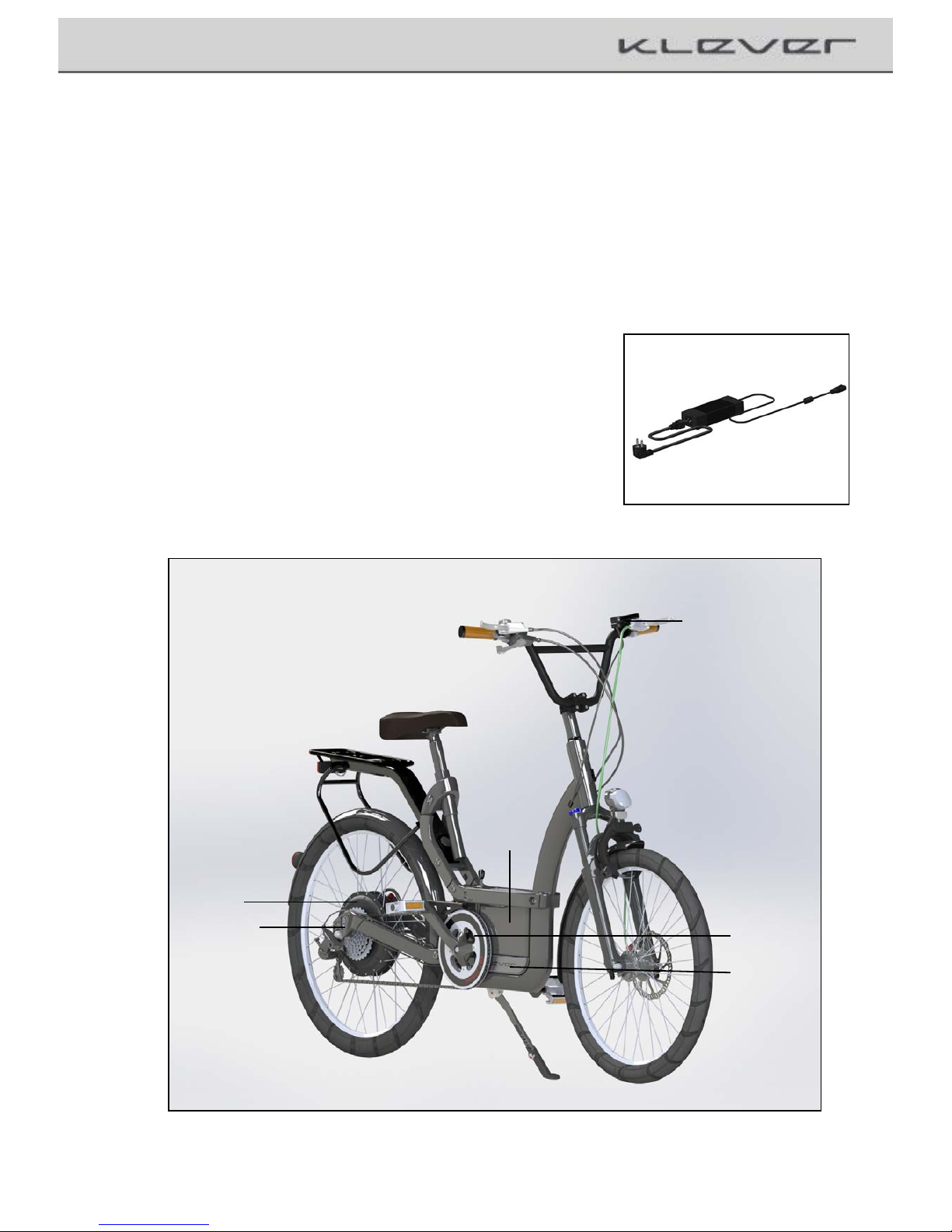
This electric auxiliary drive consists of the following components (image 8):
1. Battery
2. Engine/Motor
3. Control unit /Display,
4. Motor Controller
5. Torque sensor
6. Pedal Sensor
7. Charger (Image 8a)
Image+8a
Q( !"#$1"5)6#,$7)
2,&8509
'():0$$%19
V();"$"1/)
!"#$1"55%1
F();"$"1
Z()<"1=+%
))>%#&"1
) U()?%@05/
>%#&"1)
Image+8
11

!
Propulsion+system+of+Klever+Mobility
Once you have turned on the system (See also Section 6.3. Display) and you start pedaling the engine will
support you as long as you pedal, up to a max. speed of 25 km/h
This limitation of the support, the Pedelec moves within the legal framework of the Road Traffic Act and
is still considered as a normal bicycle. It is exempt from compulsory insurance and do not need a license.
Likewise, it is not compulsory to wear a helmet, although we strongly recommend it for your own safety.
The five (different) levels of support you can select according to the external circumstances (e.g. level four
(high level) on climbing uphill or headwind) or your personal preferences. Please note that a high level of
support also means a higher consumption of energy and reduces the range of the system and the battery.
When you drive faster than 35 km / h, the automatic energy recovery (technical recuperation) is activated.
The motor operates as a generator and charges the battery again.
If you ride your B25 beyond 40Km/h (e.g. downhill) an audio warning signal will be emitted and the system
may enter auto-protection mode. In this condition the system is still alive (e.g. display lights up,
but the motor output is temporarily shut off, and will not automatically restored.
To restore the system from auto-protection mode to normal operation, press the power key to power off
your bike and then power it on again.
U(')>%#&"1&)0#@)D+#-$,"#
The Pedelec is equipped with a torque sensor in the dropouts, which is
electronically controlled. This sensor accurately measures the change in tension
force of the chain at every step (left or right) and informs the system about the
force you exert during pedaling. A computer in the control unit then calculates
the values, with which the additional thrust of the motor it is very sensitive and
harmonious controlled.
During pedaling, the torque and the pedal sensor measure very sensitive and
exactly the drivers input and enables the motor controller to operate the
additionally support of the Motor.
The thrust itself can influence even on the five levels of support (Turbo, High,
Medium, Low, Ultra Low). This makes the system very efficient and
economically, saves power consumption and maximizing range.
The additional speed sensor controls the power of the electric motor to zero
once you have reached 25 km / h. From this and a higher speed the Pedelec
works like a conventional bicycle.
12

!
Propulsion+system+of+Klever+Mobility
But this also means that you have either to pedal or press the
Walk / boost button on the display bracket to retrieve power of
the electric motor.
This button functions as a starting and pushing aid to max.4 km/h
it helps you to accelerate from a standstill. It was designed as an
aid when starting uphill or for the case that the wheel has to be
pushed.
U(F)C%E%5&)"D)&+88"1$)
The propulsion system provides five levels of support available.
Depending on topography, weather conditions and your own
feelings, you can choose the power of the engine by using the
plus (+) and minus (-) keys and the boost button on the control
panel (see Section 6.3 display.).
13
When the button is pushed without pedaling, “Walk” mode provides motor output for <6km/h.
When the button is pushed while pedaling, “Turbo” mode provides strongest support.
>9&$%3)C%E%5)
>+88"1$)
21,E,#H)&,$+0$,"#)S1%-"33%#@%@W)
UL (Ultra Low)
No support, system is activated
downhill
L (low)
Low support
In the plain
M (medium)
Medium support
Slightly inclines; headwind
H (High)
High support
Steep inclines; fierce headwinds
T (Ultra High) (while pedaling)
Strongest support
Steep ramps; violent gusts
<6 km/h (no pedaling)
Starting and pushing aid
Starts on hill; pushing uphill
To protect battery, when charging level is below 10%, maximum support level automatically limits to M
(Medium), and L (low) when charging level below 5%, UL (Ultra low) when below 2%.

!
Propulsion+system+of+Klever+Mobility
U(Q)2,&8509
Battery State of Charge Indicator
Key 4
Key 5
Key 3
Key 6
Display of the support levels
Indication
of Speed, Day Trip
and Remaining Range
Key 1
Key 2
Image+9
The display (the control unit) is the heart of the electric auxiliary
propulsion with the display you start and control the entire electric drive
system (image 9).
`#59)K,$A)0)3"+#$%@)@,&85094)9"+)-0#)&$01$)$A%)&9&$%3(
Each bicycle has its own individually programmed display. It is not
possible to activate your Pedelc with the display of another bike, not
either of Klever Mobility. Every keystroke is confirmed by a short
audio signal.
Once the display is engaged in the bracket (image 10), there are two
ways to start the electrical system:
'( ?1%&&)0#@)A"5@)D"1)')&%-"#@4)$A%)&$01$)I+$$"# - the system runs
for 3 sec through a systems check - now the system is activated
Or
F( G"+)@1,E%)"DD)K,$A)$A%)I,.%)0#@)$1,HH%1)$A%)0+$"30$,-)K0.%)+8) )
3%-A0#,&3( There is a system check of 3 seconds and the
system is ready to go and then it supports you.
If the
bike is powered off by press power button (image3), then
the automatic start mechanism will function with 30 sec delay
after powered off. This is for the user who wants to ride the bike
under power off mode without any assistance.
By pushing the + (top left) or - (bottom left) buttons you can select
the desired levels of support in standstill or while driving.
Image+10
14

!
Key assignment:
Location
Function
Key 1
Top Right
On/Off electrical system
Key 2
Lower Right
On/Off alarm and motor lock
Key 3 (-)
Lower left
Support level; switch down
Key 4 (+)
Top left
Support level; switch up
Key 5 (Info)
Between 3 and 4
Switching between current speed,
remain range and trip distance
Display
Upper bars
Charge level indicator; five bars
of 20% each
Display
Left/three horizontal bars
Level of support:
H-High; M-Medium; L-Low
Display
Right area
Indication of: Speed; Range and day Trip
Key 6
Display holder
Starting and pushing aid; (at rest); Turbo
support; while driving
Propulsion+system+of+Klever+Mobility
15
U(Q(')a+#-$,"#)"D)%0-A)I+$$"#B
_%9)'B)>$01$7)&$"8)I+$$"#)SL30H%)''W
By pressing key 1 for 1 sec boot the system. The system performs
a system check of about 1-2 seconds, and the drive system is ready
to operate. The electric drive supports you depending on the level
of assistance during pedaling.
By pressing this button again the system turned off and all settings
are stored. Now the Pedelec works like a normal bicycle. Press the
button again, the system starts at exactly the point at which you have
turned it off and all old settings and levels of support are enabled again.
^$$%#$,"#J)^D$%1)X)3,#+$%&)"D),#0-$,E,$94) )
$A%)&9&$%3)$+1#&)"DD)0+$"30$,-0559()
Image+11

!
Propulsion+system+of+Klever+Mobility
_%9)FB)C"-.)_%9)SL30H%)'FW
By pressing the button 2 for 1 sec, the motor lock and the alarm
system are activated and the system is ready to turn off. Now
remove the display and the Pedelec is optimally protected against
theft.
Once the display is re-assembled, the engine block is removed
and disabled the alarm system.
This Lock mode only works with electricity. The battery must be
installed with little capacity. If the battery is removed, you can´t
activate the motor lock and the alarm system.
!
By moving the bike forward within this mode the alarm system will
be activated immediately and you hear a loud high-pitched alarm
signal. At the same time the engine block is activated and the wheel
can only be pushed with very great force.
!
Image+13a
Lock function_
1. Lock Button (Image 12)
2. Press the release button (Image 13a)
3. Dismantling of the display (Image 13b)
Once the corresponding display is mounted again, the alarm will
be ended and the motor lock is deactivated.
Image+13b
^$$%#$,"#B)L#)-0&%)"D)0--,@%#$05)$1,HH%1,#H)"D)$A%) )
050134)85%0&%)3"+#$)$A%)@,&8509),33%@,0$%59),#)$A%)
A"5@%1()
Image+12
_%9)QB);,#+&):+$$"#)SL30H%)'VW
By pressing the button 3, you can reduce each support level
always exactly one level. E.g. the selected support level is M
(medium), and you press 3 (-), the assistance of the electric
motor decrease by one level to L (Low).
Image+14
16
!
Propulsion+system+of+Klever+Mobility
_%9)VB)?5+&):+$$"#)SL30H%)'ZW
Pressing the button 4 you can always increase each support level
by exactly one level. E.g. the selected support level is on M
(medium) and you push the plus button, the support level of the
motor will increase exactly one level, in this case H (High)
Image+15
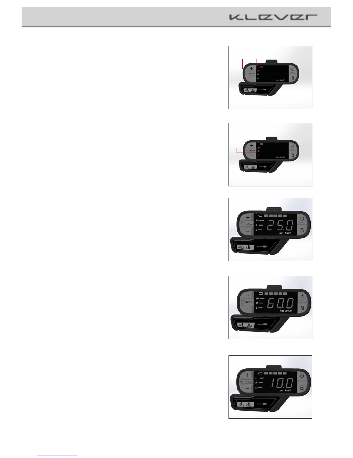
_%9)ZB)L#D"):+$$"#)SL30H%)'UW
By pressing the button 5 (info), all important information will be
accessed and displayed on the screen, which the system provides for
you.
Normally, the display shows the current speed in km/h
. (image 17a;
for example 25km/h)
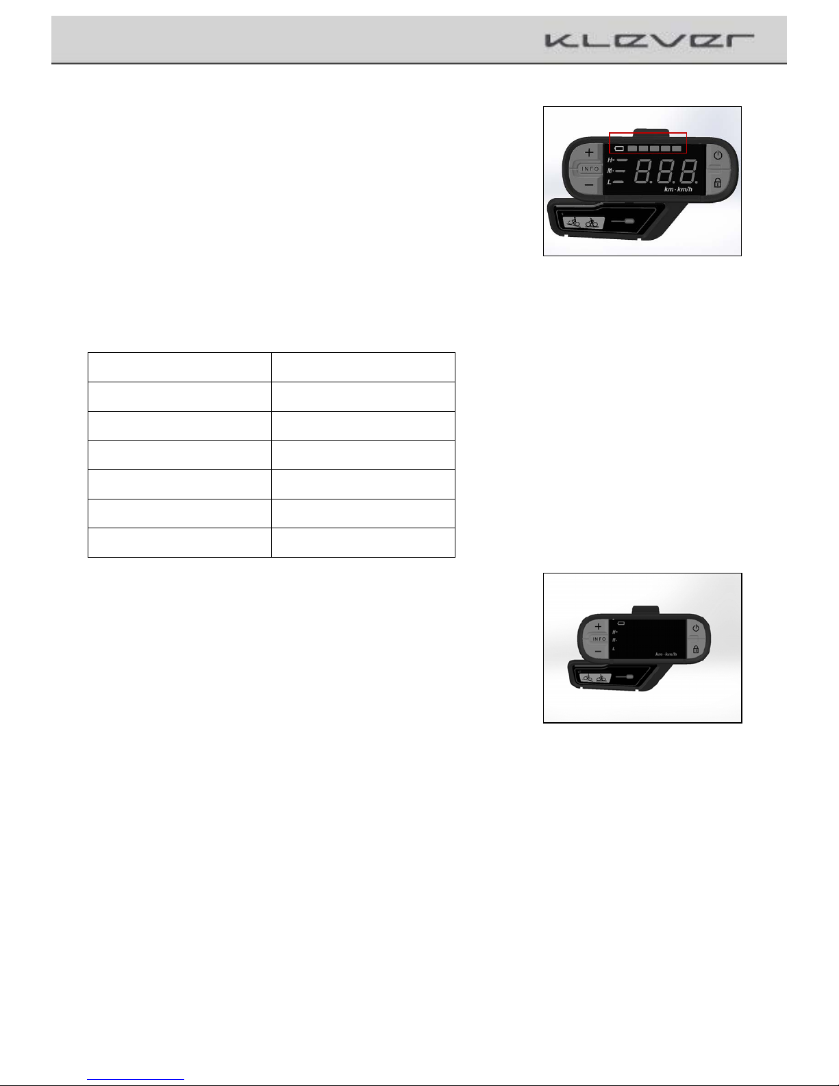
Press the Info button for one second, the display changes to the
range mode and shows the remaining range for the currently
selected power level.
Change the level by pressing the + or - button, the system calculates
the new range and displays it on the screen.(image 17b; for example
60 km)
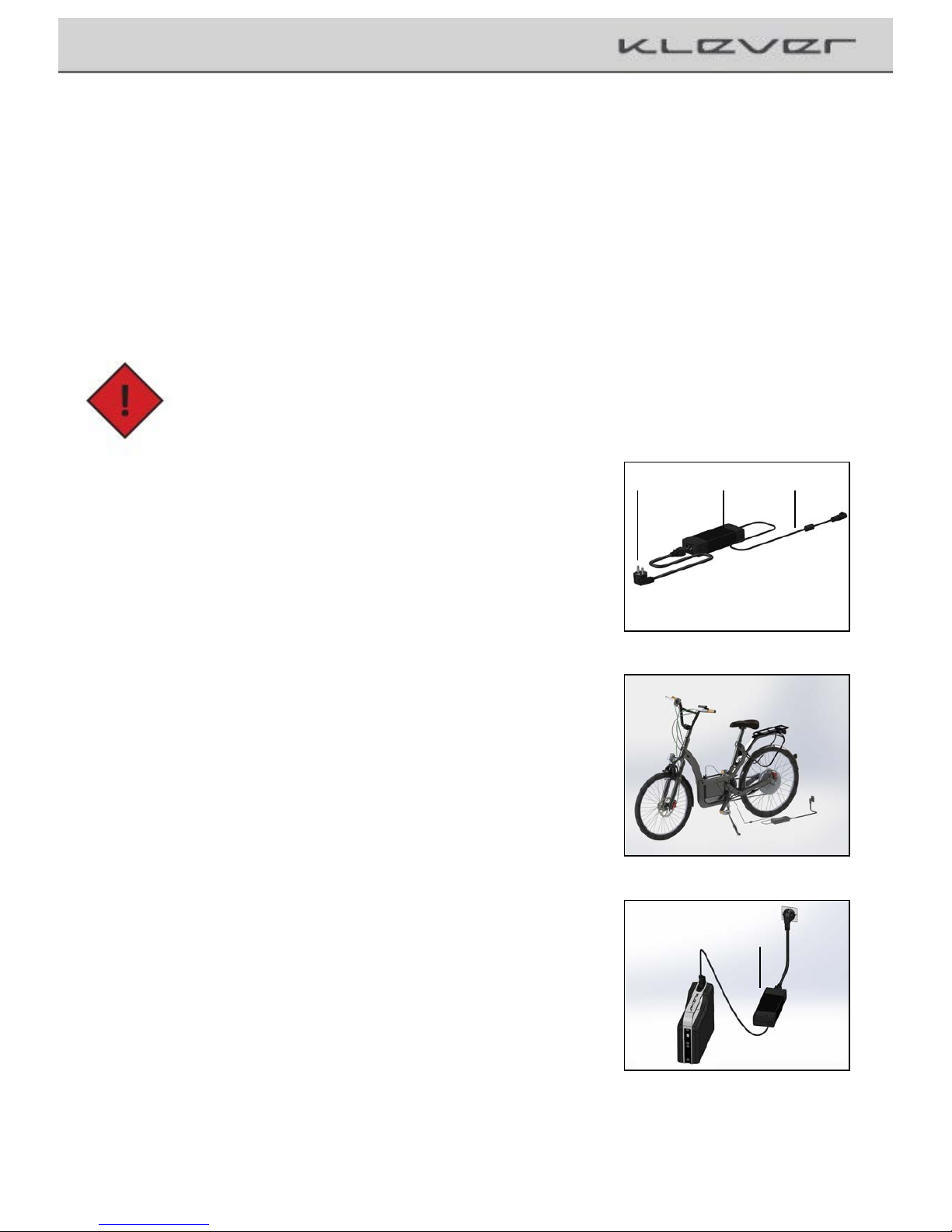
When you are you in range mode and press the Info button again for
one second, the display changes in the mileage mode. Now you will
be shown the number of kilometers since the last reset. (image 17c;
for example 10 km) Do you want to set the odometer to zero, e.g. at
the beginning of a day trip, press the Info button for two seconds,
and the display clears the kilometers and shows 0 km.
You will get back in the speed mode when you press the Info button
again for one second. After five seconds of inactivity, e.g. without
pressing any key, the system switches automatically back to the
speed mode.
Image+16
Image+17a
Image+17b
Image17c
17

!
Propulsion+system+of+Klever+Mobility
_%9)UB)O05.7:""&$):+$$"#)SL30H%)'XW
This button has two functions:
'( ^&)0)&$01$,#H)0#@)8+&A,#H)0,@B)To help you pushing and/or
starting a bicycle at a traffic light on a ramp or facilitate uphill
you can press this button. As long as you hold the button, you
receive assistance from the engine without pedaling up to max.
4 km/h) When you release the button, the support from the
motor will stop immediately.
This support only works until max. 4 km/h and when you are not
pedaling.
Y"$%B)21,E,#H)K,$A)0)&$01$,#H)A%58)A0&)$")I%)5%01#%@() )
?10-$,-%)$A,&)81"-%@+1%)"#59)"#)0)8%@%&$1,0#)&$1%%$() )
`#59)KA%#)9"+)D%%5)&%-+1%)0#@)-"#$1"5)$A%)81"-%&&4) )
@1,E%)"#)8+I5,-)1"0@&()
F( ^&)0)$+1I")&+88"1$)KA,5%)@1,E,#H()When you need extra
support for a short period, for example, on a steep ramp, press
the turbo button and get the highest possible maximum thrust
from the engine, the system can provide.
The turbo support functions independently of the pre-set level of
support.
As long as you hold the button, you get the extra boost.
When you release the button, the turbo support stop immediately
and the system continue at the previously selected mode.
Turbo mode only works when pedaling simultaneously. When you
stop pedaling and / or release the Boost button the turbo
assistance from the motor will stop.
^$$%#$,"#B)?5%0&%)+&%)$A,&).%9)0&)5,$$5%)0&)8"&&,I5%() )
L#)$A,&)&%$$,#H4)3+-A)%#%1H9),&)-"#&+3% @)0# @ )$A,&) )
K,55)&A"1$%#)$A%)10#H%)"D)$A%)&9&$%3()
)
Image+18
18
!
Propulsion+system+of+Klever+Mobility
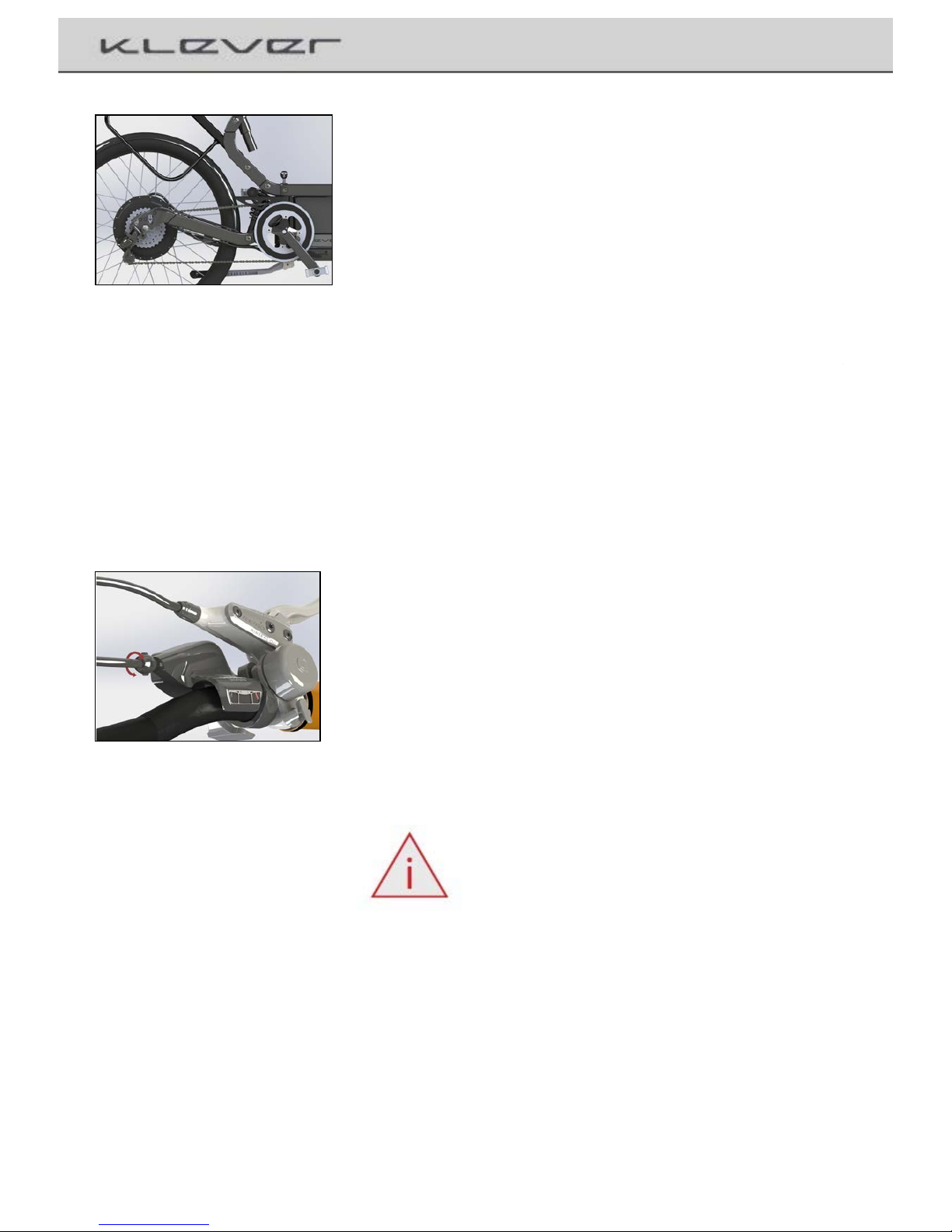
2,&8509)SL30H%)'[W
The top five bars with the battery icon show the charging status of
the battery. If the five orange bars are lights up, the battery is full
(capacity 100%).
One bar represents 20% of full capacity. If only one bar is shining,
only 20% of the maximum capacity of the battery is available.
Now the battery should be recharged as soon as possible.
When the last bar flashes, there is only 10% battery capacity
remaining. Recharging of the battery is now urgently needed.
Image+19
Additionally, you can check the charging level with the LED on the
front side of the battery. (See also Section 6.4.1. Charging the
battery)
2,&8509)"D)>+88"1$)5%E%5)SL30H%)FTW
The lit bars before the left row of numbers on the screen with the
letters H (high), M (medium) and L (Low) informing of the chosen
level of support of the electric motor.
In the right column of the table we have listed recommended
settings, in which driving situation which level will be the best to use
the system optimally and minimize power consumption. Of course it
is possible to use the levels individually, e.g. driving in the plane with
the highest level of support (H).
Image+20
19
Display
Charging level
Five bars light up
100%
Four bars light up
80%
Three bars light up
60%
Two bars light up
40%
One bar light up
20%
One bar flashes
Less than 10%

!
Propulsion+system+of+Klever+Mobility
2,&8509B)>8%%@"3%$%1)SL30H%)F'W
The main display will show you the current speed. Press for one
second the Info button, the mode switches to range mode and
you can see the remaining range of the system, with the currently chosen
level of support. Modification of the support level changes also
the range.
Press the Info button for a second again, the odometer mode
will occur and you can see the driving kilometer since the last
reset.
To reset the Odometer, you push the info button for 2 sec..
Press the Info button for one second, the display will return to
the speed mode.
After 5 sec. of inactivity the speed mode will came back
automatically.
Image+21
20
C%E%5)
2,&8509)
:+$$"#)
>+88"1$)
b,@,#H)&,$+0$,"#)
S1%-"33%#@%@W)
UL (Ultra Low)
0 bar
Minus key
No support;
System is
activated
downhill
L (Low)
1 bar
Minus or plus key
Low support
In the plain
M (Medium)
2 bars
Minus or plus key
Medium support
Slightly inclines;
headwind
H (High)
3 bars
Plus key
High support
Steep inclines;
Fierce headwind
T (Ultra High)
0 - 3 bars
additional pushing of the
Walk / boost button (button
on the display holder, boost
function works only when
pedaling can be pressed at
any support level
Strongest support
Steep ramps;
Violent gusts
< 6 km/h
0 - 3 bars
By pressing the Walk/boost
button in standstill/without
pedaling
Starting and
pushing aid
Pushing uphill;
Starting aid
To protect battery, when charging level is below 10%, maximum support level automatically limits to M
(Medium), and L (low) when charging level below 5%, UL (Ultra low) when below 2%.

!
Propulsion+system+of+Klever+Mobility
2,&8509B),55+3,#0$,"#)SL30H%)FFW
Under the battery icon on the screen hides a light sensor which
automatically adjusts the backlight of the display and it adapts
under the external light conditions.
(Outside / day 100%, at night / indoor 40%)
This ensures that you can read optimally the display in various
lighting conditions.
The lighting levels are fixed and can´t be dimmed.
Image+22
U(Q(F)^&&%3I59)0#@)@,&0&&%3I59)"D)$A%)@,&8509)
The control panel can be removed from the holder. We
recommend that whenever you want to park the bike, press the
lock button and remove the control panel. This means an
additional theft protection, because the system can only be
started with this display.
2,&0&&%3I59)"D)$A%)@,&8509
Press down the unlocking device on the mounting bracket and slide
out the display in the drive direction of the bicycle. (image 23,23a)
^&&%3I59)"D)$A%)@,&8509B
Slide in the display into the mounting bracket until it engages
audible. The system can now be started. (image 24)
Note: Make sure that the console is
properly locked so that it will not fall out
while riding and being damaged.
If the bicycle is used by several people, you can purchase from
us additional displays with the same settings, necessary for
your Pedelec. Thus, any person who uses this bike has her own
individual display.
unlocking device
Image+23
Image+23a
Image+24
21

!
Propulsion+system+of+Klever+Mobility
U(V):0$$%19
Your Pedelec has a high quality lithium-ion battery of the newest
generation. For technical details, please refer to Chapter 11 Technical
data.
The status of the battery, you can always check on the LED on the
charging socket of the battery. Press the button at the charging socket
and the LED lights on either red, orange or green.(image 25+25a)
Image+25
The battery is protected automatically from overheating, overloading and
deep discharge. That makes it, in practice very easy and simple to handle.
Nevertheless, you should consider some important things in order to
maximize the life and performance of the battery.
Since the lithium ion battery has no memory effect, you can charge it at
any time, even if it is not completely discharged. In practice, it has been
shown that it is even better to charge it again after short distances of a
few kilometers.
Your battery has a lifetime of 700 charging cycle. One charging cycle
means a full charge of the battery (0-100% capacity). Partial loads can be
done more often.
When the battery for a long time (more than 2 months) is not used, it
should be recharged as a low self-discharge is normal. Store the battery,
if possible, in a dry, cool and dark place. The ideal storage temperature is
between 5-20℃.
Avoid exposing the battery to direct sunlight over a long time.
Temperatures over a longer period of more than 45℃ or below - 10℃
can cause permanent damage.
In winter, you should never start with a cooled battery. The capacity of a
cold battery is significantly reduced and accordingly with a lower range.
A battery which is exposed a long time to frost, should be gently heated
by the ambient temperature of a heated room, before starting.
Image+25a
22
Red
capacity <35%, the battery should be charged
Orange
Capacity 35 - 75%; battery can be charged
Green
Capacity> 75% battery can be charged
Charging!Socket!
LED!

!
Propulsion+system+of+Klever+Mobility
!0+$,"#J)Y%E%1)850-%)$A%)I0$$%19)"#)$A%)A%0$%1()
If you need to park the bike outside for a long time in the cold season,
remove the battery and store it in a heated room. Because the battery is
very easy to remove, this will be no problem.
Do not expose the battery to humidity, to prevent corrosion of the charging
socket and the plug contacts. Protect the battery against mechanical damage
and don´t drop it. Mechanical damage can also cause overheating and
spontaneous ignition of the battery.
Also the battery should be charge at moderate temperatures (15-25℃).
Avoid charging in direct sunlight or near heaters, as well as charging outside
in winter at low temperature. A cooled battery should be gently heated to
room temperature before loading.
!0+$,"#B)2")#"$)8+$),$)"#)0)A%0$%14)@")#"$)A%0$)K,$A)0)
A0,1)@19%1()
!0+$,"#B)!A01H%)$A%)I0$$%19)"#59)K,$A)$A%)81"E,@%@)
%P-5+&,E%59)@%@,-0$%@)-A01H%1()
Do not use any other type of charging unit since this may damage the
battery and might cause overheating and ignition. During loading, neither
the charger nor the battery should expose to humidity, to prevent short
circuits and electric shocks.
The battery is maintenance-free. Should it be broken or getting defect,
contrary to expectations, seal the contacts with tape and take it to your
dealer or contact our technical hotline. Under no circumstances open up the
battery yourself. This is dangerous and can damage the battery lead to
self-ignition. The warranty will be void if you do so!
2")#"$)@,&8"&%)"D)I0$$%1,%&),#$")A"+&%A"5@)K0&$%()
L$)3+&$)I%)@,&8"&%@)" D)8 1" 8 %1 59()L$ c&)I%&$)$")$0.%),$)$")"#%)"D)"+1)
@%05%1&4)KA")-0#)$0.%)-01%)"D)$A%)81"8%1)@,&8"&05()
23

!
Propulsion+system+of+Klever+Mobility
!0+$,"#J
■ Charge the battery only with the provided battery charger
■ The battery can be recharged any time, even after short trips
■ Avoid temperatures below -10℃ and above 45℃ for a long
time
■ Never start with a cooled battery
■ After an extended period (about two months) of storage, the
battery should be recharged
■ Protect it from humidity
■ Protect it from mechanical damage
■ Never open the battery by yourself
Used batteries do not belong in the household
waste, Please disposed properly.
24
!
Propulsion+system+of+Klever+Mobility
U(V(')!A01H,#H)$A%)I0$$%19
You can charge the battery on or off bike (e.g. important in winter)
Charging at any time, even after a partial discharge (e.g. after a short
distance of a few kilometers) is possible. There is no need to wait
until it is completely discharged, as it has no memory effect.
To remove the battery pack, refer to Chapter 6.5.3. Disassembly and
assembly of the battery.
!0+$,"#J!A01H%)$A%)I0$$%19)"#59)K,$A)$A%)&+885,%@)0#@) )
81"E,@%@)I0$$%19)-A01H%1()
For the technical data of the charger please read chapter 11.
Technical data.
To charge the battery, do the following: You can monitor the charging
process on the basis of the indicator LEDs on the charger and battery.
■ Connect the power cable to the charger.
■ Insert the power plug of the charger into the wall socket, the LED
lights solid red the charger is ready to charge (image 26).
■ Connect the charging socket of the charger into the socket of the
battery, the charging process will start automatically (image 27
a+b).
■ The LED on the charger switches to flashing yellow light, charging
begins.
■ The LED indicator turns to yellow continuous light, the battery is
charged to about 35%, The charging is in progress.
■ The LED changes to flashing green, the battery is to about 75 - 90%
charged.
■ The LED comes on solid green, the battery is now fully charged, the
charging is complete.
■ Disconnect the power plug from the Wall socket.
■ Unplug the charger socket of the charger from the battery.
ØØ! !
Image+27b
Charger
Charger
Power!Cable!
Charger!
Power!Plug!
Image+26
Image+27a
25

!
Propulsion+system+of+Klever+Mobility
<A%)CR2)5,HA$&)"#)$A%)-A01H%1)0#@)I0$$%19)@"-+3%#$&)$A%)&$0$%)"D)$A%)-A01H%)81"-%&&B)
The charging time for a full charge (from 0 to 96% capacity) is about four hours (100%-6 hours).
;0.%)&+1%)$A0$)$A%)I0$$%19),&)#")5"#H%1)-"##%-$%@)$")
$A%)-A01H%14)0D$%1)$A%)&+--%&&D+5)-A01H%)81"-%&&()
C,.%K,&%4)$A%)-A01H%1)&A"+5@)I%)@,&-"##%-$%@)D1"3)$A%)
8"K%1)&+8859()
Battery and charger become warm during charging. Ensure
adequate ventilation of the battery and charger. The vents should
not be covered.
Place the charger and battery on clean surfaces. Prevent
contamination of the charging socket on the charger and the
battery.
Avoid humidity and direct sunlight.
^$$%#$,"#J)LD)$A%)-A01H%1),&)@030H%@4)
?5%0&%)-"#$0-$)0#)0+$A"1,N%@)1%$0,5%1()
Y%E%1)"8%#)$A%)-A01H%1()
26
State of charge
Charger LED
Battery LED
Note
Flashing Red
Error detected. Reset by re-plugging AC to main
Steady Red
Ready to be connected to battery
0%
Flashing Yellow
Flashing Red
Recovering battery from very low state of
charge
<35%
Steady Yellow
Flashing Red
Normal charging
35 – 75%
Steady Yellow
Flashing Yellow
Normal charging
75 – 90%
Steady Yellow
Flashing Green
Normal charging
>90%
Flashing Green
Flashing Green
Final charging
100 %
Steady Green
=> no LED
Fully charged

!
27
The range specification of the system can only be relative, as it is
very strong depending on the chosen level of support, the technical condition
of the bike (oiled chain, optimal tire pressure, etc.) the total weight of the
system (bike, rider and luggage) to the topography of
the chosen route and the weather (headwind-or tailwind, winter or summer).
The smaller the selected support level the longer the range of the electric
system.
U(V(F)b0#H%
■ Fully charged battery 355 Wh
■ Temperature between 12-30℃
■ Flat and slightly hilly terrain
■ Total system weight between 95-105 kg (rider
weight 70-80 kg)
■ Little to no wind
Generally, you can expect the following ranges:
^$$%#$,"#B)L#)K,#$%14)$A%)10#H%)-0#)I%)&A"1$%#)+8)$")QTd)5%&&)
I9)5"K%1)I0$$%19)-080-,$9)@+%)$")$A%)5"K%1)$%38%10$+1%&(
Propulsion+system+of+Klever+Mobility
b0#H%)
C%E%5
90km
UL (Ultra Low)
70km
L (Low)
50km
M (Medium)
40km
H (High)

!
U(V(Q)2,&0&&%3I59)0#@)0&&%3I59)"D)$A%)I0$$%19
Propulsion+system+of+Klever+Mobility
b%3"E,#H)$A%)I0$$%19)
The battery is automatically saved with the battery lock and
thereby protected from theft. Using the provided key you can
lock and unlock both, the battery lock and the frame lock onto
the frame and lock the rear wheel.
To disassemble the battery, first turn off the system using the 1
button on the Display. Turn the key in the battery lock clockwise up to
the stop and pull out at the same time on the handle the battery pack
upwards, in the direction of travel, completely out of the bracket on
the frame.(image 28a)
Now you can charge the battery separately or store it safely for a
longer ride break.
In case of disassembly we recommend, to protect the battery
connector against humidity with the rubber seal. (image 28 b+c)
;"+#$,#H)$A%)I0$$%19)
Insert the battery carefully into the guide rail, while the groove of the
battery casing must be careful inserted into the guide rail on the bicycle
frame, and let it gently down glide until you heard the lock engages and
the electronic contacts are connected. (image 29)
The key does not leave in the lock, the lock will automatically snap in
and the battery is now locked, the system is ready for operation and the
battery protected from being stolen.
Image+29
Image+28b
Image+28a
Contact! !
Connector!
Rubber!Seal
Rubber!Seal
28
Image+28c

!
Propulsion+system+of+Klever+Mobility
U(V(V)<10#&8"1$)"D)$A%)I0$$%19
The battery is subjected to the Dangerous Goods Legislation requirements.
The user can transport the battery by road and train without further
requirements.
When being transport by third parties (e.g. forwarding, post or via air) special
requirements on Packing and labeling must be observed
For preparation of the item being transported, consulting an expert for
hazardous material is absolutely required.
Use the battery only when the casing is undamaged. Tape or mask off open
contacts and pack up the battery in such a manner that it cannot move around
in the packing.
Please also observe possibly more detailed national regulations.
L#)%E%19)-0&%)"D)-"#-% 1# ,#H )$1 0# & 8" 1$ )"D )$A %)I 0 $$% 19 4)8 5% 0& %)1 %D %1 )
$")0#)0+$A"1,N%@)I,-9-5%)@%05%1()
U(Z)<1"+I5%&A""$,#H)
<A%)&9&$%3)K,55)#"$)$+1#)"#) )
)
Check whether the display is firmly in the bracket. Check all
connections. Check the battery. It must sit correctly in the battery
seat of the frame and the lock is closed.
<A%)@,&8509),&)D,P%@)I+$)$A%)&9&$%3)K,55)#"$)$+1#)"#B)
Check if you have installed the correct display.
<A%)&9&$%3)-0#)I%)$+1#%@)"#4)I+$)9"+)@")#"$)A0E%)&+88"1$)
Check all connections to the motor
LD),$e&)#"$)8"&&,I5%)$")&"5E% )$A %)8 1" I 5% 34)85%0&%)-"#$0-$)0#)
0+$A"1,N%@)@%05%1)"1)"+1)$%-A#,-05)A"$5,#%()
29

!
The+Bicycle
\()<A%):,-9-5%
All other accessories of your Pedelec are high quality, conventional
bicycle components whose handling and operation should be
explained here briefly. Important information regarding the
adjustment, operation and maintenance of the bike and its
accessories are summarized here.
You will also find further information in the accompanying user
manuals of each manufacturer.
\(')>0@@5%)0#@)A0#@5%I01)0@f+&$3%#$)
The B25 comes in only one frame size. The adjustment to your
body size and their needs will be made on the saddle, stem and
handlebar adjustment, which normally do the authorized dealer.
In order to readjust by yourself or in the case of a driver change the
settings are briefly described in the following lines.
!0+$,"#B)^55)K"1.)@%&-1,I%@)1%=+,1%)3%-A0#,-)%P8%1,%#-%)
0#@)0881"81,0$%)$""5&()6&%)$")$,HA$%#)$A%)&-1%K&)0)
$"1=+%)K1%#-A)0#@)#%E%1)%P-%%@)$A%)30P,3+3)$"1=+%)
"D)$A%)&-1%K&()^55)$A%)#%-%&&019)$""5&)0#@),#D"130$,"#)$")
$A%)$"1=+%&)-0#)I%)D"+#@),#)-A08$%1)'')<%-A#,-05)20$0()
)
Image+30
^@f+&$3%#$)"D)$A%)&0@@5%)A%,HA$B)
The optimal saddle height is if you touch the pedal with the heel
of your stretched leg, when sitting on the saddle (Image 30).
Or when you bring the ball of the foot to the center of the pedal,
your knee should be slightly bent. (Image 31)
Loosen with a suitable allen key the seat clamp screw and move
the seat post with the saddle at the proper height. Align the saddle
with the frame using the saddle nose and the bottom bracket or
top tube as references.
Fasten the screw of the seat clamp again and check the correct
height of the saddle. Repeat the process if necessary until you find
the correct saddle height.
Image+31
30

!
The+Bicycle
The distance between saddle and handlebar (by pushing the saddle
forward or backward) and the saddle angle are adjusted by the saddle
clamping screws (Image 32) of the seat post. The saddle should
generally be positioned horizontally.
^$$%#$,"#B)85%0&%)809)0$$%#$,"#)$")$A%)0881"E%@)$"1=+%&)
KA%#)$,HA$%#,#H)$A%)&0@@5%)-5038)&-1%K&)$")$A%)-"11%-$)
$"1=+%)S&%%)-A08$%1)'')<%-A#,-05)@0$0W()
!0+$,"#B)<A%)&0@@5%)K,$A)$A%)&%0$)8"&$)309)#%E%1)I%)
,#&$055%@)"E%1)$A%)3 ,# ,3+3)301.)"#)$A%)&%0$)8 " &$ () )
S,30H%)QQW2+1,#H)1,@,#H)"8%10 $," #4)$A% )8" &$)3 ,H A$)I 1%0 .) )
"1)$A%)D103%)3,HA$)I%)@030H%@()
)
Saddle!Clamping
Screw
Image+32
g0#@5%I01)0@f+&$3%#$)
The position of the handlebar depends on the Seat position you would
like to have on your bike. You can optimal your seat position by
adjust the handlebars angle to your needs, (image 34).
Your dealer will be happy to advise and install the most appropriate
stem for your needs and will adjust the handlebar position.
If you should like to change the position after some time, please do
the following:
Minimum!
Inserting! !
Mark
Image+33
Image+34
31

!
The+Bicycle
!0+$,"#B)!A%-.)$A%)$,HA$#%&&)"D)$A%)A0#@5%I01()L#)#")
-0&%),$)309)I%)0I5%)$")$K,&$()
Would you change now the position of the brake levers and the
gear shifter, loosen the clamp screws and twist them according to
your wishes. Then tight the clamping screws again. (image 36)
Image+36
!0+$,"#B)2"#e$)%P-%%@)$A%)30P,3+3)$"1=+%&(SU/XY3W)
Image+35
\(F)g%0@&%$)
Headsets
In order to steer easily and safely, the fork´s bearing in the frame
headset (image 37) must be of easy motion and without play.
During driving, dynamic loads caused by extremely unevenness
routes put a lot of stress on the headset and it is possible that it
loosens. Therefore, a regular check is indispensable.
Pull the front wheel brake with one hand and push the bike
forward and backward. If you notice a movement between headset
and frame, the headset has to be readjusted.
Image+37
^$$%#$,"#B)<A%)0@f+&$3%#$)"D)$A%)A%0@&%$)1%=+,1%&)
&"3%)%P8%1,%#-%()L$),&)$A%)I%&$)$A%)@%05%1)&A"+5@)@")
$A,&()
)
32
Loosen carefully the clamp screws of the stem where the
handlebar is camped. (image 35)
Then turn the handlebar according to your wishes. Your wrists
should be as relaxed as possible and not turned too far to the
outside. Then pull gently on the handlebar clamp bolts of the stem
back and pay attention to the maximum torque of the screws.
(max. 5,5. Nm)
Please note that now the brake levers and the gear shifter have
changed their position.
!

!
The+Bicycle
If you should make the adjustment by yourself, make the following steps:
1. Loose with an allen wrench, the lateral clamping screws at the stem,
where the stem is fixed on the fork stem.(Image 38)
2. Now you can adjust the headset play with the top screw of the
headset (see image 39), by turning the screw with a 6mm allen key
clockwise, until you don´t feel play anymore.(Image 39)
^$$%#$,"#B)<A,&)&-1%K)@"%&)#"$)&%1E%)D"1)$,HA$%#,#H4)I+$)
"#59)D"1)0@f+&$,#H)"D)$A%)A%0@&%$()SL30H%)Q[W)
3. Rearrange stem and handlebar in the direction of travel and
retighten the clamping screws firmly.
4. Pay attention to the maximum torque of the screws, which may not
be exceeded under any circumstances.
5. Control the play again and repeat the process if necessary.
LD),$e&)#"$)8"&&,I5%)$")0@f+&$)$A%)A%0@ &% $4)$A,&)3 0 9)A0 E% )3 0 #9 )
1%0&"#&()L#)$A,&)-0&%)9"+)&A"+5@)@%D,#,$%59)-"#$0-$)0#)0+$A "1,N% @)
@%05%1()
!0+$,"#B)a,#05594)-A%-.)$A%)$,HA$#%&&)"D)$A%)& $% 3()^)5""&%)&$%3),&)
@0#H%1"+&)0#@)-0#)5%0@)$")0#)0--,@%#$()
You can check smooth running by lifting the front of your bike and letting the
handlebar swing to the left and right. The front wheel has to be able to move
freely and without stopping. If you feel slight stops in the movement, the
bearing is worn and the headset has to be replaced. This has to be done
quickly by a dealer.
a%%5)5,HA$)H1,@&4)$A%)$0P)10$%)01%)K"1#)"+$)0#@)#%%@)1%850-,#H() )
<A%)5%$)3"&$),33%@ ,0 $% 59 )I 9 )$A%)@%05%1)8%1D"13()
Image+39
Image+38
33

!
The+Bicycle
\(Q)>+&8%#&,"#)D"1.)
Your Pedelec is equipped with a high-quality suspension fork which
increases your comfort and the safe handling of the bike. The fork
is set at the factory and ready to run.
A lock out lever that sits on the right side of the fork crone, you can
lock your suspension fork (image 40). This locking mechanism
should only be used on smooth, flat roads. On bad roads, the spring
should function and the lock mechanism should always be open.
To keep your fork for a long time working, it should be regularly
maintained. Some basic maintenance tips you should heed. Clean
the smooth surface of the stand pipe of the fork after every ride
with a clean cloth and some water. Afterwards spray the tubes with
some lubricating spray or some hydraulic oil, so it can smooth
deflecting and the bearings remain always lubricated.
!0+$,"#B)G"+)&A"+5@)#%E%1)-5%0#)$A%)D"1.)%,$A%1)K,$A)0)
&$%03)-5%0#%1)"1)K,$A)A01&A)@%$%1H%#$&()^5K09&)D"55"K)
$A%)30,#$%#0#-%)0#@)-01%),#&$1+-$,"#&)"#)$A%)
30#+D0-$+1%1c&),#&$1+-$,"#&)&+885,%@)K,$A)$A%)I,.%()
Image+40
\(V):10.%&
Your Pedelec is equipped with a high-quality Tektro hydraulic disc
Brake (image 41). The disc brake is characterized by a very good
braking action even by moisture and other bad weather conditions.
The brake is very low maintenance and does not wear the rim.
The brake consists of a brake lever with a master cylinder, a hose
cable made of plastic and the brake caliper and the disc mounted
on the hub. The brake works with a special, non-toxic mineral oil.
The oil pressure created in the brake lever by operating it is
transmitted via hose cable to the brake cylinder and effect the
contact pressure of the brake pads at the brake disc.
Image+41
34

!
The+Bicycle
^$$%#$,"#B)
Y%K)I10.%)80@&)3+&$)I%)1+#),#)&")$A0$)$A%9)-0#)0-A,%E%)$A%,1)
"8$,305)@%-%5%10$,"#)E05+%&():9)I10.,#H)0$)5%0&$)QT)$,3%&)D1"3)
0881"P,30$%59)QT).37A)$A%)I10.%)80@&)K,55)0-A,%E%)$A%,1)
30P,3+3)I10.%)8"K%1()
Not properly run in brakes do not reach their optimal deceleration values and
prone to vibrations and loud squeal.
The brake pads and rotors must be regularly checked for wear.
If Disc and brake pads are worn, they will need to be replaced.
Changes in the brake performance with loosing brake power or you can push
the lever through to the handlebar without any braking effect, air could come
into the brake system and this must be removed by bleeding the brake. That
and the replacement of worn brake pads and discs should be done by an
authorized dealer.
^$$%#$,"#J)>",5%@)I10.%)80@&)0#@)@,&-&)-0#)1%@+-%)$A%)%DD%-$)"D)
$A%)I10.%)&+I&$0#$,0559()?1%E%#$),#)0#9)-0&%4)KA ,5%)-5%0# ,#H)$A% )
I,.%)0#@)5+I1,-0$,#H)$A%)-A0,#)$A0$)",5)"1)"$A%1)5,=+,@&)-0#)
-"#$03,#0$%)$A%)I10.%)80@&)0#@)I10.%)@,&-&() )
!"#$03,#0$%@)I10.%)80@&)-0##"$)I%)-5%0#%@)0#@)#%%@)$")I%)
1%850-%@()G"+)-0#)-5%0#)$A%)@,&-)K,$A)I10.%)-5%0#% 1)"1)K0 13 )
K0$%1)0#@)0)5,$$5%)@%$%1H%#$),D)#%-%&&019()
J)?5%0&%)@1,E%)E%19)-01%D+559),#)K%$)K%0$A%1)-"#@,$,"#&();",&$+1%)
309)-0+&%)5"#H%1)I10.,#H)@,&$0#-%&()
For more information on brake, brake pad and brake disc and the wear limit of
them, read the operation manuals supplied by the manufacturer.
35
!
The+Bicycle
\(Z)21,E%)0#@)H%01&A,D$)
Your Pedelec is equipped with a high-quality 10-speed derailleur,
currently the most efficient power transfer on the bike. These gears
will help you to always use the optimal transmission (pedaling
cadence) independent of terrain (flat or hilly area) and independent
of weather (Tail or Headwind).
That means that you are able to pedal always with an optimal
cadence of 60-80 crank revolutions per minute. The complete
system (image 42) is composed of the bottom bracket, the crankset,
the rear derailleur, the chain, the gear shifter and the 10-speed
cassette. With the gear shifter you control the rear derailleur,
which ensures that the chain can move on the sprockets of the
freewheel and the translation changes.
Your dealer has checked your bike before the handover and
adjusted the shifter. Through the first mile under stress, however,
the shift cables could lengthen slightly and the shifter must be
readjusted.
With the adjustment screw of the shifting lever (image 43), you can
readjust the tension of the shift cable. With the two positioning
screws on the rear derailleur, you can adjust the lower (h screw)
and upper end stop (l-screw), to make sure, that the chain cannot
get between pinion and drop out or between pinion and spokes of
the rear wheel.
Please read also the enclosed operating instructions of the
manufacturer of derailleur and shifter.
Image+43
<A%)81%-,&%)0@f+&$3%#$)"D)$A%)@%10,55%+1),&)@,DD,-+5$)0#@)
&A"+5@)I%$$%1)I%)@"#%)I9)0)3%-A0#,-&()LD)9"+)A0E%)0#9)
81"I5%3&)K,$A)$A%)0@f+&$3%#$)"D)$A%)&A,D$%14)85%0&%)
-"#$0-$)9"+1)@%05%1()
The chain should be cleaned and greased regularly (especially after
driving in the rain), so it runs as quietly as possible, the friction
losses are as low as possible, and the lifetime is maximized. Clean
the chain regularly with a clean cotton cloth and lubricate it
afterwards.
Some minutes after you have oiled the chain rub it with a cloth to
remove superfluous oil from the outer surface.
Image+42
36

!
The+Bicycle
Since the chain is one of the wear parts on your bike, it should, if it is worn
to be replaced. A worn chain deteriorating the shifting characteristics, and
leads to increased wear on the chain wheel and on the sprockets of the
cassette.
<A%)%P0-$)-"#$1"5)"D)$A%)-A0,#)&A"+5@)I%)-011,%@)"+$)0$)$A%)@%05%14)
KA")A0&)$A%)#%-%&&019)$""5&)$")3%0&+1%)0#@)1%850-%),$()
!0+$,"#B)^)8""159)1,E%$%@)"1)I0@59)K"1#)-A0,#)309 )I 1% 0 . )0# @ )
-0+&%)&%1,"+&)D055&()
)
You will find more information in the enclosed operating manual of the chain.
37

!
The+Bicycle
\(U)C,HA$,#H
Your Pedelec is equipped with a high quality bike lights
corresponding to the StVZO and have an official mark. This is
indicated by the wavy line with the letter K, and a five-digit
number.
The lighting is supplied through the hub dynamo in the front wheel.
The headlight is a high quality LED head lamp with high light output
and light function. The taillight is also a bright LED light with light
function integrated at the carrier.
On the back side of the front lamp, there is the light switch.
The light switch has tree steps:
`#
^+$"
Switch on; continuous light; also during the day
Switch on; automatically controlled from a light sensor;
turn on when it is getting dark
Switch off; no light
`DD)
If there is a failure in the lighting system please verify that the light
is switched to the "on" position, check all contacts at Dynamo,
headlight and taillight. Check all cables for damage.
If you don´t find any errors, you are looking for repair at an
authorized dealer immediately.
!0+$,"#B)^)#"#/D+#-$,"#,#H)5,HA$),&),55%H05)0#@)
%#@0#H%1&)9"+1)5,D%)"#)$A%)1"0@():,-9-5%&)K,$A"+$)5,HA$&)
01%)%0&,59)"E%15"".%@),#)$A%)@01.()G"+)K"+5@)1,&.)
&%1,"+&)0--,@%#$&()
For further information on the hub dynamo, headlight and tail
light, see the accompanying user manuals of each manufacturer:
If you have further questions, please contact the dealer or our
technical hotline.
38

!
The+Bicycle
\(\)OA%%5&)0#@)$,1%&
The wheels are extremely stressed parts of the bike that make contact
with the road, provide the propulsion and buffer the road bumps. Due
to this heavy use, they should be regularly monitored and reviewed.
All wheels are manufactured with great care and precision.
They consist of the hub (dynamo hub in the front wheel and electric
motor in the rear), the high-quality stainless steel spokes and rims. (2
mm spoke in front wheel and 2.3 mm spoke in rear wheel)
In unlikely cases of radial and axial offset or broken spokes, the wheels
should be repaired or re-centered immediately.
This should be done by an authorized dealer.
For removal and installation of the wheels due to a puncture or in the
case of transportation you take the following steps:
2,&0&&%3I59)"D)$A%)1%01)KA%%5)
■Shift the chain to the smallest sprocket on the free wheel
■Turn off the electric drive system and disconnect the motor connector
below the right chain stay of the frame
■Remove the screw on the mounting bracket and cable guide (image
44 a+b) below on the chain stay
■Loosen the axle nut of the motor with a 19 mm wrench
■Remove the screw of the locking washer (image 45) on the left side of
the axle (drive direction) and remove the screw and washer
■Now pull the wheel out of the dropout, thereby pivot the rear
derailleur backwards
Locking Washer
Motor Connector
Image+44a
Image+44b
Image+45
39

!
The+Bicycle
■Ensure the disc-brake with the enclosed transport lock (between
the brake pads; image 46).
■This prevents the accidental compression of the pads by the
unintended application of the lever
■The assembly is done in reverse order
■During assembly please insert carefully the disc between the brake
pads, please remove the transport lock in advance.
Image+46
!0+$,"#B)<0.%)-01%)$")$,HA$%#)$A%)0P5%)#+$&)$")$A%)81"8%1)
$"1=+%)SVT)Y3WJ)
a1"#$)KA%%5)SL30H%)V\W
■Disconnect the plug connector from the hub dynamo
■Loosen the axle nut of the front axle with a 15mm wrench
■Pull the front wheel out of the dropouts of the fork
■Secure analogous to the rear wheel the disc brake with a
transport lock
■The assembly is done in reverse order
■During assembly please insert the disc carefully between the
two brake shoes
■Take care when tightening the axle nuts to the proper torque
(20 Nm)
Image+47
Y"$%B)b"$"1&)-0#)I%)E%19)A"$)0D$%1)@1,E,#H()C%$)$A%3) )
-""5)@"K#4)I%D"1%)@,&3"+#$,#H()
!0+$,"#B)!A%-.)I%D"1%)9"+)1,@%)$A%)$,HA$#%&&)"D)$A%) )
KA%%5&()
40

!
The+Bicycle
<,1%&
The tire provides grip and traction, and contributes significantly to the
smooth running and comfort by absorbing small shocks.
The size of the tire can be found on the tire sidewall printed specifically
in millimeters and inches. At B25, the size 24 x 2.0 inches or 50 - 507 is
mounted. That is, the tire has a diameter of 507 mm (24 inches) and a
width of 50 mm (2.0 inches). Depending on the air pressure, and width
of the rim, the tire can vary in width around 2-3 mm.
The manufacturer's recommended operating pressure can be found
printed on the tire sidewall (Schwalbe Big Apple 2.5 to 5.0 bar; 35-70
psi).
Regularly check the correct tire pressure before every ride and pump
up, if necessary.
The bike is standard equipped with an inner tube with auto valve. So
you can check and inflate the tire at any gas station.
!0+$,"#B)Y%E%1)%P-%%@)#%,$A%1)0I"E%/#"1)I%5"K)$A,&)
1%-"33%#@%@)10#H%()<A%)$,1%)0#@ )$A%)$+I %)-0# )I%)
@030H%@)0#@)$A,&)309)5%0@)$")&+@@%#)5"&&)"D)0,1)K,$A)
&,H#,D,-0#$)1,&.)"D)0--,@%#$()
Regularly check the tires for cracks and control the tread depth. If cracks
have formed or a foreign object has damaged the fabric of the tire or the
tread depth is no longer sufficient, replace the tires for safety reasons.
If in doubt, ask your dealer. He will verify and if necessary, change the
tire.
Image+48
41

!
The+Bicycle
In the case of a flat tire, you do the following:
You can use plastic tire level for tire mounting.
1. As described above dismount the appropriate wheel like in the
instructions of this manual.
2. Deflate the tire and push a tire lever under the tire wire opposite the
valve and lever the tire over the rim flange.
3. Push the second tire lever in a distance of approx.. 10cm from the
first one between tire and rim and lever again. (image 49)
4. Now, you can generally lever the tire over the whole circumference of
the wheel by moving the lever and the inner tube can be removed.
5. Dip the disassembled and inflated tube in a water bath to discover
the leak on the rising air bubbles.
6. Repair the tube according to the instructions on the repair kit or if
necessary replace it.
7. Check the tire for sharp objects that could have caused the puncture
and remove them. If the fabric of the tire is damaged, replace it.
8. Start the mounting of the tube, start by inserting the valve into the
valve hole in the rim and inflate the tube with very little air pressure
until it is wrinkle-free.
9. Now mount the tube with no creases under the tires and deflate it
again. (image 50)
10. Now, starting opposite the valve, lift the tire wall over the flange of
the rim and pull it deep into the rim and lever the rest of the tire by
hand over the rim edge. Use no tire levers, as this is a risk of
damaging the tube.
11. Now push up the valve, so that the edge of the tire reaches at the
valve area the edge of the rim.
12. Pull the valve and inflate the tube to the tire manufacturer
recommended tire pressure.
Image+49
Image+50
42

!
The+Bicycle
\(X)C+HH0H%)-011,%1&
Your Pedelec is equipped with a high quality, stable and durable
aluminum luggage rack of Racktime, where a high-quality LED taillight is
integrated.
Please note that mounting panniers is not recommended. A pannier
mounted on the luggage carrier of B25 may be too close to the rear
wheel and causing the danger of riding. If you need to mount a pannier,
please purchase and install additional rack stays.
Please note, however, the maximum load capacity of the luggage rack
of 25 kg. With weights over 25 kg the luggage carrier may not be loaded.
At press time of the manual the carrier was not officially approved for
fitting child seats. Please inform yourself on the homepage of Racktime
www.racktime.de before installing a child seat on the carrier.
!0+$,"#B)?5%0&%)%#&+1%)$A0$)9"+)@")#"$)1%0-A)$A%) )
$"$05)8%13,$$%@)K%,HA$),#)$A%)-0&%)"D)5+HH0H%)$10# &8 "1$()
Image+51
^$$%#$,"#B)?5%0&%)#"$%)$A0$)$A%)%P$10)K%,HA$)-A0#H%&)$A%)
A0#@5,#H)"D)$A%)I,.%)0#@)$A%)I10.,#H)@,&$0#-%),&)%P$%#@%@()
43
Additional rack stay
(non-standard part)

!
The+Bicycle
\([)!A,5@)&%0$
You should install only an appropriate DIN / GS approved child seat.
Read and adhere to the instruction manuals of the seat manufacturer.
Children may only be taken on special seats where the feet are
securely fixed. In Germany, the child may be max. seven years old, and
the driver must be at least 16 years old. If you are traveling in another
country, check their rules and regulations.
At press time of the manual the carrier was not officially approved for
fitting child seats. Please inform yourself on the homepage of
Racktime www.racktime.de before installing a child seat on the
carrier.
!0+$,"#B)<0.%)$A%)-A,5@)"+$)"D)$A%)&%0$)KA%#)9"+)801.)$A%)
I,.%()`$A%1K,&%4)$A%1%),&)0-+$%)@0#H%1)"D)D055,#H()
Y"$%B)<A%)-A,5@)&A"+5@)05K09&)K%01)0#)0881"81,0$%)
A%53%$)KA%#)&,$$,#H),#)$A%)&%0$()?5%0&%)#"$%)$A0$)0)-A,5@)
&%0$)K,$A)0)-A,5@)$A%)A0#@5,#H)"D)$A%)I,.%)H1%0$59)0DD%-$%@()
<A%)I,.%)$%#@&)$")5+1-A()<A%1%D"1%4)9"+)&A"+5@)810-$,-%)
&$01$,#H)0#@)@1,E,#H),$)I%D"1%)$0.,#H)801$),#)$A%)1"0@)
$10DD,-()2")#"$)%P-%%@)$A%)30P,3+3 )8%13 ,$$%@ )K %,HA $)"D)
'VZ).H)"D)$A%)I,-9-5%()
44
\('T)<A1%0@&)D"1)A0#@5%)I01)0@08$%1)"#)A%0@)$+I%) )
In the head tube of your Pedelec, two head tube threads allow
you to assemble a KLICKfix handlebar adapter for head tube, by
which you can mount a bag or basket in front of your Pedelec.
Information and instruction about the suitable adapter and
various bags and baskets can be found in the website of
KLICKfix: http://www.klickfix.de/.
Please note that the distance between two threads is 16mm.
Use screws M6x16 only while mounting a handlebar adapter for
head tube, otherwise the head tube might be damaged.

!
The+Bicycle
\('')C"-.&)0#@)0#$,/$A%D$)&9&$%3)
Your bike is standard additionally equipped, apart from the already
mentioned motor blocking (see Section 6.3 Display), with a high
quality frame lock on the front of the frame (image 52), to protect it
optimally against theft. This lock can lock the front wheel.
^$$%#$,"#B)O,$A)$A%)&03%).%9)9"+)-0#)-5"&%)$A%)
I0$$%19)5"-.)0#@)D103%)5"-.()G"+)#%%@)D"1)I"$A)5"-.&)
"#59)"#%).%9()
)
Only when the frame lock is locked you can remove the key out of
the lock.
<")5"-.4)9"+)@")$A%)D"55"K,#HB)
)
Turn the key clockwise until the stop and slide the knob on the other
side of the lock down until the small steel bracket snapped in, the
lock closed and the front wheel is blocked. Now you remove the key.
The bike is now well protected against theft.
With the key you can now, if desired, open the battery lock to
remove the battery (see also 6.4.3. disassembly and assembly of the
battery).
To do so, please follow these steps. Insert the key into the battery
lock and turn the key clockwise (image 53) until the stop and pull the
battery on the handle upward from the bracket. If the battery is
removed, you can snap back the key and remove it.
When mounting the battery, please pay attention to the correct
orientation. The groove in the battery casing has to be inserted into
the guide rail on the bicycle frame.
Push it down until it audible snaps in and the electrical contacts
between the battery and control unit are connected. The battery
lock is closed automatically.
During installation, the keys must not be located in the battery lock.)
45
Image+52
Image+53

!
The+Bicycle
For further theft protection, you can now activate the lock function
of the electric system by pressing the Lock button (right side,
bottom button) on the display and removing it afterwards (see also
Chapter 6.3 display).
The bike is now optimally secured against theft and the alarm
system and motor lock are activated.
As soon as the corresponding display is again mounted in the
holder, the lock function is cancelled.
\('F)^--%&&"1,%&
Useful accessories can increase the usefulness of your pedelec and
significantly increase your riding pleasure. For example, you can
use baskets of Racktime, which you can connect securely with one
hand with the carrier mounted on your B25. More useful and good
accessories are available at your dealer, who can advise you.
!0+$,"#B)^55),$%3&)$A0$)9"+)8+1-A0&%)&A"+5@)K,$A&$0#@)
$A%)1%=+,1%3%#$&)"D)$A%)b"0@)<10DD,-)0#@ )$A%)1%5%E 0# $)
2LY/&$0#@01@&)0#@)I%)-"380$,I5%)K,$A)9"+1)I,.%()
6#&+,$0I5%)0--%&&"1,%&)-0#)-A0#H%)$A%)A0#@5,#H)
-A010-$%1,&$,-&)"D)$A%)KA%%5)0#@)5%0@)$")0#)0--,@%#$()
:%&$)0&.)0)@%05%1)D"1),#D"130$,"#)0#@)0@E,-%()
46

!
Transport+of+the+bike
X()<10#&8"1$)"D)$A%)?%@%5%-
You can transport your Pedelec easily by car or train. To transport by
cars, we recommend to use a bike rack for the trailer hitch, which is
specific designed for the e-bike transport and suitable for larger loads.
Which carriers comply with these requirements, you can ask the
retailer.
Not recommended is the transport on the car roof. The higher weight
and the specially shaped frame tubes make it very difficult to fasten
the bike securely. In addition, permissible maximum weight and to
tightly sized brackets and rails of the carrier limit secure
transportation.
You should definitely remove before transportation with the battery,
the display as well as other non-fixed accessories such as: Air pump
and luggage bags Additional protection should be given to electrical
contacts on the display holder and the battery connector on the frame
with for example a plastic bag to protect them from moisture and rain.
By the air stream, humidity can be pressed into the electrical contacts.
If your car is big enough, the best is to transport it in the inside. There
it is optimally protected.
The transportation by air is almost impossible, unless you want to
transport the bike without the battery. The battery is classified as
hazardous by the airlines and will not be transported. If in individual
cases ask the airlines, under which circumstances the transport of the
battery may be possible. However, it can be quite expensive.
If you need further information, you will find it in this manual, see
chapter 6.4.4. Transport of the battery.
47

!
Maintenance,+care+and+storage
[();0,#$%#0#-%4)!01%)0#@)>$"10H%)
;0,#$%#0#-%)0#@)-01%)
Regular maintenance and care guarantee a longer lifespan of your
high-quality Pedelec.
You should carry out simple cleaning and care works yourself regularly
and let the dealer do the necessary inspections.
Never clean the Pedelec with a strong jet of water or a steam cleaner.
The high water pressure might squeeze water into the bearings, motor
and electronic contacts and will destroy these parts due to thin the
bearing grease, corrosion and short circuits.
Clean the bike with a damp cloth and mild detergent. Please make sure
that no electrical contact gets wet.
The contacts can be maintained and conserved from time to time with a
little care oil (e.g. 1Step Finish Line) preservation. Contact spray is too
aggressive and don´t preserve.
You should repair varnish damages at once. All parts liable to corrosion
should be maintained and preserved by appropriate means.
The chain should be lubricated regularly like all other movable
mechanical parts such as the joints of the rear derailleur.
!0+$,"#B)2+1,#H)-5%0#,#H)0#@)5+I1,-0$,"#4)0E",@)",5)0#@)D0$) )
"#)$A%)I10.%)80@&)0#@)I10.%)@,&-&()<A%)I10.,#H)%DD%-$)3,HA$)
@%$%1,"10$%)0#@)1%81%&%#$)0)&%1,"+&)1,&.
.
^5K09&)%#&+1%)$A0$)$A%)$,1%&)01%),#D50$%@)K,$A,#)$A%) )
30#+D0-$+1%1c&)1%-"33%#@%@)"8%10$,#H)81%&&+1%4)KA,-A) )
-0#)I%)D"+#@)81,#$%@)"#)$A%)"#)$A%)$,1%)&,@%K055()L$)&A"+5@) )
I%)I9)#")3%0#&)"E%1/"1)+#@%1/&$%8&()
The entire electrical system of your Pedelec as the controller, the motor, the
sensors, the wiring and the battery is maintenance-free. If you get
unexpected problems with the system, take note, that you have
to contact or technical hotline (see also Chapter 1 Introduction)
or an authorized dealer.
48

!
+ Maintenance,+care+and+storage
!0+$,"#B)2")#"$)"8%#)$A%)-"#$1"55%14) ) $A%)3"$"14)$A%)@,&8509)"1)
$A%)I0$$%19()
L$),&)@0#H%1"+&)0#@)$A% )H+ 0 10 # $% %)% P 8 ,1% &),33%@,0$%59()
>$"10H%)
The mounting of the bike should always be in a dry, covered place to
minimize the effects of weather and avoid direct sunlight for long
periods.
If you do not drive in winter, you should consider the following tips:
Store it cleaned, lubricated and well preserved in a dry place and
cover perhaps additionally with a tarp. Conserve the electrical
contacts through some suitable care oil.
Winter storage in the garage is only partially recommended. By the
dissolved salt in the condensed water coming with the car in the
garage, the corrosion can be increased.
The battery should be stored separately and recharge to 75% SOC (the
LED indicator just turn green) before storage. Battery should be
recharged at least every two months. (see chapter 6.4 Battery).
'T()2,&8"&05
2,&8"&05
All electronic components, such as motor, display, battery and charger
are to be returned to an environmentally compatible recycling and do
not belong in the trash.
For EC Countries:
^--"1@,#H)$")$A%)R+1"8%0#)2,1%-$,E%)FTTF7[U7R!4)@%D%-$,E%)"1)#")
5"#H%1)+&0I5%)%5%-$ 1,-0 5)% = + ,8 3%#$)3+&$)I%)-"55%-$%@)&%8 0 10 $ %59 )
0#@)1%$+1#%@)$")0#)%#E,1"#3%#$0559)D1,%#@59)1%-9-5,#H()<A%)&03%)
H"%&)D"1)I0$$%1,%&)0--"1@,#H)$")$A%)R+1"8%0#)2,1%-$,E%)
FTTU7UU7R!()
)
?5%0&%)1%$+1#)I1".%#)"1)@%D%-$,E%)I0$$%1,%&)$")0#)0+$A"1,N%@)
1%$0,5%1()
49

!
Disposal
<10#&8"1$0$,"#B
Only the battery is considered to be hazardous and subject to the
Dangerous Goods Legislation requirements during transport or shipping
by third parties (agents, air transportation or mail).
Please refer to Chapter 6.4.4.Transport of the battery.
The transport of all the other parts is not particularly limited.
50

!
2,&8509)7)`8%10$,#H)+#,$
Removable and illuminated LCD display, with alarm and motor lock system
Five levels of support
Zero - Low - Medium - High - Turbo – Walk/Starting Aid
Bicycle Computer, display of speed, range and Odometer (Day trip)
Key: acceleration and pushing aid / Turbo function
Battery charge level indicator with five LEDs (each bar 20% Capacity)
Ambient Light sensor
Confirmation by a beep when a button is pressed
Technical+Data
''()<%-A#,-05)@0$0)
)
51
:0$$%19
Lithium-Ion Battery
44.4V / 8.0Ah / 355wh
2.7 kilograms
Charging level indicator via LED: <35% red / orange 35-75% /> 75% Green
Allowable discharge temperature: -20℃ - +50℃
Allowable storage temperature (12 months): -20℃-+25℃ (optimal +5℃-+20°C)
Allowable charging temperature range: -5℃ - +45℃ (+5℃-optimal +20℃)
Lockable and detachable
Charging time 6 hours (from 0 -100%) or 4 hours (from 0-95%)
Place of loading: on or off-bike
Charging Cycles 700 (one charging cycle 0-100% capacity)
Range: Step 1 (UL) = ca.90km / Level 2 (L) = ca.70km / Level 3 (M) = 50 km / Level 4 (H) = ca.40km
Lifetime: after two years or 700 cycles still remain at least 60% of the original capacity
;"$"1
Brushless DC motor in the rear hub
Control over torque sensor in the dropout and speed sensor at the bottom bracket
Max. 250 W
Operating voltage 44 V
Support until max. 25km/h
Weight 4.4 kg

!
Technical+Data
!A01H%1!
Input voltage 200-240 V, 47-63 Hz!
Output voltage of 48 V !
Maximum charge current 2A!
Output power 96 watts!
Charge time 6 for 8 Ah battery (0-100% capacity) or 4 hours (0-95%)!
Size: 167 x 65 x 41 mm, no fan!
Weight: 0.6kg (with AC cable)!
52
b%-"33%#@%@)$,HA$%#,#H)$"1=+%&)"D)$A%)I,-9-5%)-"38"#%#$&B) )
)
Stem
Handlebar clamp screw
M5
Allen wrench 4mm
5.5 Nm max.
Stem
Clamp screw adjusting angle
M6
Allen wrench 5mm
9.5 Nm max.
Stem
Clamp screw steer tube
M6
Allen wrench 5mm
9.5 Nm max.
Seat post
Clamp screw saddle
M6
Allen wrench 5mm
9.5 Nm max.
Seat post Clamping
screw
Clamp screw for seat post
M5
Allen wrench 4mm
5.5 Nm max.
Front wheel
Axle nut; Hexagon
9mm axle diameter
15mm open-end wrench
20 Nm max.
Rear wheel
Axle nut; Hexagon
12mm axle diameter
19mm open-end wrench
30-40 Nm
Rear wheel
Clamp screw locking washer
M5
Allen wrench 3mm
5.5 Nm
Stand
Clamp screw
M10
Allen wrench 8mm
46 Nm max.
Brake lever
Clamp screw
M6
Allen wrench 5mm
9.5 Nm max.
Brake body
Mounting screw
M6
Allen wrench 5mm
9.5 Nm max.
Brake
Mounting screw
M5
Torx25
5.5 Nm max.
Shifting lever
Clamp screw
M6
Allen wrench 5mm
9.5 Nm max.
Carrier
Clamp screw
M5
Allen wrench 4mm
5.5 Nm max.
Carrier
Clamp nuts; Hexagon; self-locking
M5
8mm open-end wrench
5.5 Nm max.
Pedals
15mm small open-end wrench
35 Nm max.
Button bracket
Bearing cups
BSA Threat
Special bearing tool
50-70 Nm
Crankset
Mounting screw
M10
Allen wrench 8mm
45 Nm max.
Derailleur
Mounting screw
M10
Allen wrench 5mm
8-10 Nm
Derailleur
Clamp screw cable
M5
Allen wrench 5mm
6-7 Nm
Derailleur
Clamp screw jockey wheels
M4
Allen wrench 3mm
2.5-5 Nm
Front lamp
Clamp screw
M6
Allen wrench 5mm
9.5 Nm
)
)
]%#%105)30P,305)&-1%K)$,HA$%#,#H)$"1=+%)SD"1)H1%0&%@)2LY)&-1%K&WB)
Screw
M4
M5
M6
M8
M10
Tightening torque in Nm
2.9
5.5
9.5
23
46
)

!
Technical+Data
The torque indications always refer to the upper limit of the screws
resilience.
You should always adjust the torque key to a little more than 50% of
the value stated by the manufacturer and tighten the screw. Check the
firm fit of the connection afterwards.
If the clamping connection is not strong enough, increase the value
gradually in steps of 0,5 Nm.
If necessary, adjust the maximal value (never exceed it) and loosen the
screw by half a revolution before finally tightening it.
<""5&B
Tools
Combination+Wrenches
Sockets+and+Bits
Torque+Wrench
Torx
Tire+Lever
<A%)H1"&&)E%A,-5%)K%,HA$)"D)$A%)I,.%B)
Rider + bicycle + luggage = 150 kg
<,1%&B
Size: 24 x 2.0, 50-507
The recommended air pressure: 2.5-5 bar;
Circumference approximately 1910 mm.
The exact circumference of the wheel depends on the
air pressure and the weight load of the bike.
53

!
Guarantee
'F()C,0I,5,$9)D"1)30$%1,05)@%D%-$&)0#@)K0110#$9)
By on 01.01.2002 entered into force European warranty law you
are entitled to a warranty period of two years. This applies from
the date of purchase or delivery (delivery date) of the Pedelec. The
proof is the proof of purchase, which you should be stored
carefully. Also you should be registered your bike on our
homepage: www.klever.mobility.com.
This liability for material defects applies to all accessories of the
entire Pedelec.
O0110#$9)-50,3&)01%)0E0,50I5%B)
■ if the fault was present before the purchase of the Pedelec
■ in the case of a material, manufacturing or information error
■ if no function-related wear was present (see Chapter 14)
O0110#$9)-50,3&)01%)#"$)0E0,50I5%B)
■ For damages caused by accidents or force majeure
■ For damages caused by misuse or mishandling
■ when relates to parts which have a functional wear subject (see
Chapter 14) excepted material or workmanship errors
■ For damages caused by inadequate care and maintenance
■ for damages caused by faulty repairs
■ for damage caused by additionally installed accessories that are
not included in delivery
■ for consequent damage caused by not immediately resolved,
early identified deficiency
54

!
Guarantee
In addition, we provide a comprehensive warranty that
goes beyond the liability for material defects.
■ <K")9%01)K0110#$9 on all bike parts
■ <A1%%)9%01)K0110#$9)on all drive modules of the electrical
system: motor control unit, display and cabling
■ <K")9%01)K0110#$9)on the battery
■ a,E%)9%01)K0110#$9 against frame breakage
This warranty applies only to the original owner on presentation of
proof of purchase (sales receipt or bill showing the purchase date). This
warranty covers exclusively material and workmanship errors.
In case of justified complaints, the article will be replaced or repaired.
Further claims such as: replacement of property damage, downtime,
cost of borrowing and renting, travel and transportation costs or loss of
profits, are excluded.
This warranty does not cover damages caused by misuse function, by
wear and tear, by accidental damage, vandalism and by improper
assembly or repair.
1. Warranty repairs will be made exclusively by Klever Mobility or an
authorized dealer.
2. Costs through a prior executed repair of an unauthorized dealer, will
not be reimbursed.
3. Parts replacement or repairs during the warranty period will not result
in an extension or a new beginning of the warranty.
4. Each battery is subject to a natural aging process. Regarding the battery
Klever Mobility guarantees after two years, or alternatively, after 700
charging cycles (which come first) a remaining capacity of about 60% of
the original capacity.
5. The Two-year warranty begins on the date of purchase. A warranty
claim must be notified immediately.
55

!
Normal+use
'Q()L#$%#@%@)6&%
Your Pedelec is determined according to their structural requirements
for a particular purpose. Thus, the usage is limited to specific areas.
Your Pedelec is designed based on the construction and equipment for
use on public roads on normal roads and paved roads.
The bicycle is equipped in accordance with the Road Traffic Regulation
(StVZO) and therefore allowed to drive on public roads. To keep your
bike always running and roadworthy, regular reviews and inspections
are required or necessary repairs should be made immediately.
Klever Mobility is not liable if the Pedelec is used against its original
purpose or for damages resulting from a breach of important
instructions in this manual.
This is particularly true in case of damage caused by overloading or
off-road use or by the improper disposal of defects. The same applies
to non-compliance with the prescribed maintenance, operation and
maintenance requirements that are described in this manual.
56

!
Wear
'V()O%01
Your Pedelec as technical product consists of many components, which
are subject to normal wear due to their function. Therefore, all the
following components should be regularly checked and if necessary
replaced immediately:
'( :10.%)2,&-&)0#@)80@&)are claimed during each braking operation and worn
appropriately. Therefore, they must be periodically reviewed and if
necessary, be replaced immediately.
F( <,1%&)0#@)$+I%& are subject to a function-related wear and should be
checked regularly. Regularly check the air pressure and tread depth. The air
pressure should always be at the manufacturer's recommended operating
pressure, which is printed on the tire sidewall.
Is the profile of the tire no longer deep enough or the tire has cracked
sidewalls, it should be replaced immediately.
Q() )b,3&)0#@)&8".%& are stressed at every braking or driving over an obstacle.
Regularly check the concentricity of the rim and the spoke tension. If the
wheel has a radial or axial offset, it should be readjusted immediately. In the
event of breakage of a spoke, the broken spoke should be immediately
replaced and the wheel has to be centered.
V() )!A0,#4)&81"-.%$4)-A0,#)KA%%5&)0#@)@%10,55%+1)1"55& wear out normally at
every time. Regular cleaning and lubrication of these components can be
extended considerably their service life. They should, however, if they are
worn be replaced immediately.
Z() )>A,D$,#H)0#@)I10.%)-0I5%& must be maintained regularly and replaced if
necessary. Especially the bike is often parked outdoor and exposed to the
weather.
U() )g9@10+5,-)",5&)0#@)5+I1,-0#$& change over time and lose their effectiveness.
Therefore, all lubrication points are regularly cleaned and re-greased to
minimize the wear.
\() )<A%)80,#$,#H)requires regular care. Check regularly all the paintwork for
damage and rectify this immediately. The points at which cables can
rubbing the painting, you should be protect them with a little clear,
transparent film.
57

!
Legal+requirements+
'Z()C%H05)1%=+,1%3%#$&)D"1)801$,-,80$,"#),#)$10DD,-)
To participate in public transport, the Pedelec must be equipped
according to the national road traffic regulations (in Germany StVZO)
If the bike will be driven or purchased in a different country than the
BRD, familiarize yourself with their national road traffic regulations.
The following technical equipment is requiring by the German Road
Traffic Regulations (StVZO):
1. Every bike must have a bright sounding bell.
2. Each bike must have two independently functioning brakes.
3. Every bicycle must have a complete lighting system.
4. Front and rear light must be operated by a Dynamo.
5. The rated capacity must be at least three watts and the rated voltage
must be 6 volts.
6. The rear light with red light has to be attached on the bike at least 25
cm above the ground.
7. The light beam of the headlight may illuminate the road at most 10 m
in front of the bicycle.
8. Front, a white reflector has to be mounted, which may be combined
with the front light.
9. Two red rear reflectors have to be mounted one must have a Z marking.
One of the reflectors may be combined with the rear light.
10. Each pedal has to be equipped with a yellow, front and rear reflector.
11. Each wheel must have at least two yellow fix mounted, side reflectors.
Alternative may also be mounted two white reflective rings over the
entire wheel circumference to the side walls of the tires or rims.
A battery powered lighting may be mounted separately.
58

!
Reqular+inspections+–+inspection+plan
'U()b%H+501)L#&8%-$,"#&)h),#&8%-$,"#)850#)
To keep your Pedelec always roadworthy and be updated to the latest
technical status, it should be inspected regularly.
We recommend after 500 - 1,000 km or within a year to carry out the
first inspection. Any further should be carried out after 2000-3000
kilometers or once a year.
^#),#&8%-$,"#)&A"+5@)I%)30@%)I9)0#)0+$A"1,N%@)@%05%1()
!0+$,"#B)LD)L#&8%-$,"#&)01%)#"$)-011,%@)"+$)"1)@"#%)
+#81"D%&&,"#054),$)-0#)&,H#,D,-0#$59),380,1)$A%)D+#-$,"#&)"D)
9"+1)I,.%)"1)%E%#)0)&%E%1%4)8"&&,I59)%E%#)D0$054)0--,@%#$()
'\()a^*&B
g"K)D01)-0#)L)$10E%5)K,$A)"#%)I0$$%19)-A01H%i)
)
This is dependent on the temperature, the topography of the
terrain, the technical condition of the total weight of the bicycle.
Tires with low air pressure or high weight or driving in hilly terrain,
reduce the range (see chapter 6.4.2.).
;+&$)$A%)I0$$%19)I%)%38$9)I%D"1%)L)-0#)-A01H%),$i)
)
No, you can charge the battery at any time, even if it is only partially
discharged.
)
g"K)-0#)L)81"$%-$)$A%)I,.%)D1"3)$A%D$i)
)
Your Pedelec is equipped with a ring lock mounted on the rear
wheel to lock the rear wheel. In addition, the Pedelec has a motor
lock and alarm system, which can be activated by the lock button
on the display. The battery is protected by the battery lock to
protect it against theft. With the key you can lock both locks, the
battery and the frame lock.
)
59

!
FAQs
!0#)L)$10#&8"1$)$A%)?%@%5%-)E,0)0,1i
Because the battery is considered to be dangerous, many airlines
refuse to transport the battery. If in individual cases ask your
airline, under which conditions and costs a transport may be
possible.
2")L)#%%@),#&+10#-%i
No, you do not need insurance. Because the electric support will
be stopped from 25 km/h the Pedelec is considered as a normal
bike and requires neither insurance nor a license plate yet.
OA0$)@")L)@")K,$A)0)@%D%-$,E%)I0$$%19i)
)
Defective batteries do not belong in household waste and must be
disposed of properly. It is best to take it to an authorized dealer.
g"K)30#9)$,3%&)-0#)L)-A01H%)39)I0$$%19i)
)
We guarantee that the battery after 700 full charge cycles or two
years from now owns 60% of the original capacity. Of course, you
can charge the battery more often or use longer than two years.
But because of the natural aging process over time the battery
loses more and more capacity.
j",@)$A%)K0110#$94),D)L)@")#"$)&$,-.)$")$A%)1%-"33%#@ %@ )
1%H+50159),#&8%-$,"#&i)
)
No, the warranty does not expire. We recommend, however, for
your own safety to carry out all in this manual described and
recommended inspections.
!0#)L)-A01H%)$A%)I0$$%19)K,$A)0#"$A%1)-A01H%1i)
)
Never!!! The battery may only be charged with the appropriate,
supplied charger.
60

!
Bicycle+passport
'X():,-9-5%)80&&8"1$
Fill out immediately all data after purchase in order to present the pass in the case of warranty
claims, together with proof of purchase. If your Pedelec is once stolen, the data facilitate the
work of the police.
61
Y03%)
>$1%%$
?"&$-"@%)7)<"K#
<%5
R30,5
<98%)"D)I,.%
a103%)&,N%
a103%)-"5"1
a103%)#+3I%1
_%9)#+3I%1)
:0$$%19)#+3I%1
!A01H%1)#+3I%1
20$%)"D)8+1-A0&%
>,H#0$+1%

!
Inspection+plan
'[()L#&8%-$,"#)850#)
62
'[()L#&8%-$,"#)850#)
)
'()L#&8%-$,"#
20$%B
After 500-1000 miles or within 1 years of purchase.
20$%
>$038)7)>,H#0$+1%
b%80,1&
b%850-%@)-"38"#%#$&
V()L#&8%-$,"#
20$%B
After 3000-4000 miles or within 2 years of purchase.
20$%
>$038)7)>,H#0$+1%
b%80,1&
b%850-%@)-"38"#%#$&
V()L#&8%-$,"#
20$%B
After 5000-7000 miles or within 3 years of purchase.
20$%
>$038)7)>,H#0$+1%
b%80,1&
b%850-%@)-"38"#%#$&
V()L#&8%-$,"#
20$%B
After 7000-9000 miles or within 4 years of purchase.
20$%
>$038)7)>,H#0$+1%
b%80,1&
b%850-%@)-"38"#%#$&

!
Imprint
FT()L381,#$
Editor, photography, text, graphic design and text:
Klever Mobility Europe GmbH
Dieselstr. 6
D-50859 Köln
Tel: +49 2234 93 342 0
Fax: +49 2234 93 342 24
Mail: info@klever-mobility.com
Web: www.klever-mobility.com
Technical modifications regarding the information and illustrations
in this manual are reserved.
A liability of publishers and other third parties for contributions
from this manual and the fact devoted damages of any kind are
excluded.
© Copyright
All rights reserved. Reprinting, translation and copying of any kind
or any other use, such as on electronic media, even in part without
written permission of the Klever Mobility Europe GmbH is not
allowed.
Aug 1, 2013 edition
63
 Loading...