

Klereo Kompact Installation Manuals

SWIMMING POOL MONITORING SYSTEM
Installation manual
Read carefully and keep for future reference. Please study the manual closely, before
bringing the system into service (Version 3)
1 - The content of this booklet may be modified without prior notice.
2 - Printing restrictions mean that the displays shown in this booklet may vary from those
actually appearing on the product.
3 - The content of this booklet may not be reproduced in any way without the manufacturer's
permission.

Klereo Kompact installation manual V 3
2
Table of contents
1. KLEREO KOMPACT MODELS DESCRIPTION .............................................................................................................. 4
1.1 T
HE 4 KLEREO KOMPACT KITS
............................................................................................................................................ 4
1.2 K
LEREO KOMPACT KITS CONTENTS
...................................................................................................................................... 5
1.3 K
LEREO KOMPACT CONTROL BOX DISPLAY
............................................................................................................................ 5
2. USAGE LIMITATIONS ............................................................................................................................................... 6
3. HYDRAULIC INSTALLATION...................................................................................................................................... 6
3.1 B
EFORE STARTING INSTALLATION
........................................................................................................................................ 6
3.2 I
NSTALLATION DIAGRAM
: .................................................................................................................................................. 7
3.3 H
YDRAULIC ACCESSORIES POSITIONING
................................................................................................................................ 8
3.3.1 Holding collars (optional) ...................................................................................................................................... 8
3.3.2 The multi-sensor tube (optional) ........................................................................................................................... 8
3.3.3 T shape collar (optional) ........................................................................................................................................ 8
3.3.4 Chamber of analysis (optional) .............................................................................................................................. 8
3.4 F
IXING THE PROBES
. ......................................................................................................................................................... 9
3.5 I
NSTALLING THE FLOW SWITCH
......................................................................................................................................... 10
3.6 C
ONNECTING THE PIPES OF THE METERING PUMPS
............................................................................................................... 11
3.7 I
NSTALLING THE WATER TREATMENT TANKS AND INJECTIONS
.................................................................................................. 12
3.8 I
NSTALLING THE SOLENOID VALVE FOR KOMPACT WITH BROMINE OR CHLORINE TABLETS
............................................................. 14
3.9 I
NSTALLING THE CELL WITH KLEREO SALT CHLORINATOR
....................................................................................................... 15
4. ELECTRICAL INSTALLATION .................................................................................................................................... 16
4.1 C
ONNECTING THE SENSORS
............................................................................................................................................. 16
4.2 C
ONNECTING THE POWER SUPPLY
..................................................................................................................................... 17
4.3 C
ONNECTING THE INPUTS OUTPUTS
.................................................................................................................................. 17
4.4 C
ONNECTING FILTERING
.................................................................................................................................................. 19
4.5 C
ONNECTING LIGHTING
.................................................................................................................................................. 20
4.6 A
DDITIONAL POSSIBLE CONNECTIONS FOR THE AUX B DOUBLE RELAY OUTPUT
. .......................................................................... 21
4.7 C
ONNECTING THE SALT CHLRORINATOR
............................................................................................................................. 21
4.7.1 Connecting the cell to Klereo Salt ........................................................................................................................ 21
4.7.2 Connecting Klereo Salt to Klereo kompact.......................................................................................................... 22
4.7.3 Connecting K-link communication bus line ............................................................................................ 22
4.8 C
ONNECTING THE TRANSFORMER AND THE SOLENOID VALVE FOR KOMPACT BROMINE
................................................................ 23
4.9 C
ONNECTING THE HEATING SYSTEM
.................................................................................................................................. 23
4.10 220V
INPUT –
IJ
INPUT
.................................................................................................................................................. 23
4.11 C
ONTACTS INPUTS
......................................................................................................................................................... 24
5. START UP .............................................................................................................................................................. 25
5.1 K
LEREO DISPLAY
............................................................................................................................................................ 25
5.2 M
AIN MENU
: ............................................................................................................................................................... 26
5.3 I
NTERFACE
: .................................................................................................................................................................. 26
5.4 E
NTERING POOL AND FILTERING CHARACTERISTICS
: .............................................................................................................. 27
5.5 C
ALIBRATION AND CHECKING OF PROBES
............................................................................................................................ 28
5.5.1 Calibration of pH probe ....................................................................................................................................... 28
5.5.2 Checking ORP probe (when used) ........................................................................................................................ 29
5.6 R
EGULATIONS TEST
........................................................................................................................................................ 29
5.7 D
ISINFECTANT SET-UP
.................................................................................................................................................... 30
Define the choices for disinfectant from the menu: ...................................................................................................... 30
5.8
PH CORRECTING AGENT SET-UP
........................................................................................................................................ 31

Klereo Kompact installation manual V 3
3
Define the choices for pH treatment from the menu: ................................................................................................... 31
5.9 S
ENSORS VALUES
........................................................................................................................................................... 31
5.10 P
ROGRAMMING REGULATION TARGET VALUES
.................................................................................................................... 31
5.10.1
Balanced pH ............................................................................................................................................... 31
5.10.2
pH target value .......................................................................................................................................... 32
5.10.3
Disinfectant target value ........................................................................................................................... 32
A
. I
N CASE OF LIQUID CHLORINE AND BROMINE
: ..................................................................................................................... 32
B
. I
N CASE OF KLEREO SALT AND ACTIVE OXYGEN
: ................................................................................................................... 32
C
. ORP
SECURITY
.............................................................................................................................................................. 33
5.11 E
QUIPMENTS SET-UP
..................................................................................................................................................... 33
5.12 O
UTPUTS ASSIGNMENT
.................................................................................................................................................. 34
5.13 H
EATING
..................................................................................................................................................................... 35
5.13.1
Heating set-up............................................................................................................................................ 35
5.13.2
Adjusting target value for heating ............................................................................................................. 36
5.13.3
Matching a Klereo Therm heating pump ................................................................................................... 36
5.14 S
ENSORS SET-UP
........................................................................................................................................................... 39
5.15 P
RIORITIES AND SECURITIES SET-UP
................................................................................................................................... 40
5.16 I
NPUTS SET-UP
.............................................................................................................................................................. 40
5.16.1
Flow switch ................................................................................................................................................ 41
5.16.2
220V input .................................................................................................................................................. 41
5.16.3
Inputs status............................................................................................................................................... 41
5.17 P
ROGRAMMING MODES FOR FILTERING, LIGHTING AND AUXILIARIES OUTPUTS
: ......................................................................... 41
5.18 S
ELECTING THE CONTROL MODES
: ..................................................................................................................................... 42
APPENDIX 1: MENU MAP ............................................................................................................................................... 43
APPENDIX 2: ACTIVE CHLORINE ACCORDING TO FREE CHLORINE AND PH LEVELS (WATER AT 25°C WITHOUT STABILIZER)
....................................................................................................................................................................................... 47
Klereo Kompact installation manual V 3
4
1. KLEREO KOMPACT MODELS DESCRIPTION
Kompact regulates the filtering cycles depending on the water temperature and the pool
characteristics (volume in m3, power and flow rate of the filter pump). It regulates also the pH
and disinfectant. There are 4 Kompact models according to the selected disinfectant: liquid
Chlorine / Salt Chlorinator / Bromine or Chlorine tablets / active Oxygen.
Klereo Kompact allows piloting 2 more outputs: pool lighting, cleaning robot, spa, counter
current system, garden lighting, fountain, and so on.
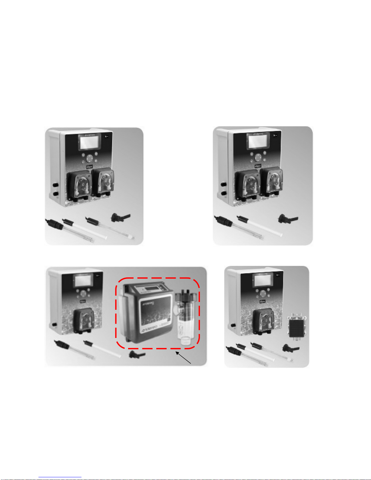
1.1 The 4 Klereo Kompact kits
Klereo Kompact liquid Chlorine
Klereo Kompact Salt Chlorinator
Klereo Kompact active Oxygen
Klereo Kompact Bromine
*
Also compatible with any Salt Chlorinator on the market
Figure 1. The different Klereo Kompact regulation kits
Klereo Salt
Chlorinator
delivered in a
separate parcel *
Klereo Kompact installation manual V 3
5
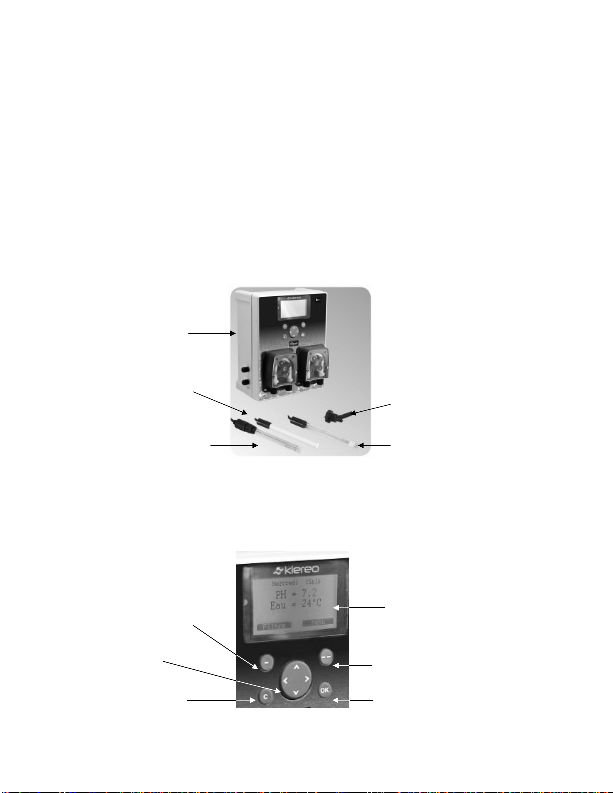
LCD screen
Validation
Screen selection key
Shortcut or screen
selection key
Back or cancel
1.2 Klereo Kompact kits contents
The Klereo Kompact kits consist of the following items:
• A control box unit equipped with 1 or 2 metering pumps according to the selected
disinfectant system
• 1 Salt Chlorinator for the Klereo Kompact Salt (delivered in a separate box))
• A flow switch sensor mounted on a Ø 50mm T shape collar (for Ø 63mm tube, please
order the reference KL10-PCS63)
• A water temperature sensor
• A pH probe
• An ORP probe (only for the Klereo Kompact liquid Chlorine or Bromine models)
• Probe holders and accessories for injection (pipe, teflon, anti return valve…)
• Setting solutions pH4 and pH7
• ORP 468 mV solution (for the liquid Chlorine and Bromine models).
• The tool to insert wiring cables
• The installation manual, maintenance and user manual as well as the warranty (to return
to us)
Figure 2. Klereo Kompact liquid Chlorine kit contents as an example
1.3 Klereo Kompact control box display
It is the interface between the user or the installer and the Klereo system.
The display enables to visualize the pool parameters and to pilot the following pool functions:
filtration, lighting, heating or other auxiliaries.
Figure 3. Klereo Kompact display and navigation buttons
Browse
Kompact
control box
Water
temperature
sensor
Flow switch
sensor
pH probe
ORP probe
Klereo Kompact installation manual V 3
6
2. USAGE LIMITATIONS
The installation must meet the following conditions to ensure the Klereo system operates
correctly:
– Pool containing no more than 200 m3 water by volume.
– The Klereo Kompact control box unit is not fitted with electrical modules to drive
directly the filter pump. You need to make the connection with the filter pump control box
equipped with a thermal overload circuit breaker and a contactor.
– Water pressure: 1.5 bar max
– Minimum water flow rate: 4m3/h
– Maximum water flow rate for the probes: 18 m3/h
– Klereo is suitable for traditional installations using sand or cartridge filters.
– Disinfectant used previously: liquid Chlorine, Chlorine tablets, active Oxygen, UV,
Ozone and salt chlorinator (non-stabilized salt), Bromine.
– The TH value (hardness) must be between 10°F and 2 5°F (or 100 to 250mg/l). The
TAS value (alkalinity) must be between 5°F and 20°F (or 50 to 200mg/l).
– If stabilizer is used, it must not exceed 75mg/l (we advised not to exceed 50 mg/l). If
the rate exceeds this, it is advisable to drain some or all the water from the pool, to avoid
upsetting the measurements, so that the pool is effectively disinfected.
– Automatic filter adjustment depends on the water temperature as well as on the
volume of water and pump flow rate. The pump flow rate must be sufficient to renew the
volume of water in the pool every 4 to 6 hours, in order to ensure this function operates
correctly.
– For solar heating used with another heating system (electric, heat exchanger or
pump), the installation must have several water temperature sensors fitted. In some cases,
Klereo may not be able to run the heating system correctly (consult Klereo).
– When the disinfectant is a salt chlorinator, it is very important to install a ground
pool before the heating system and before the salt chlorinator.
3. HYDRAULIC INSTALLATION
3.1 Before starting installation
Let the pH and ORP probes sit in a glass of tap water for at lest 30 minutes so that they will
be ready for calibration. Do it before starting installation in order to save time later on.
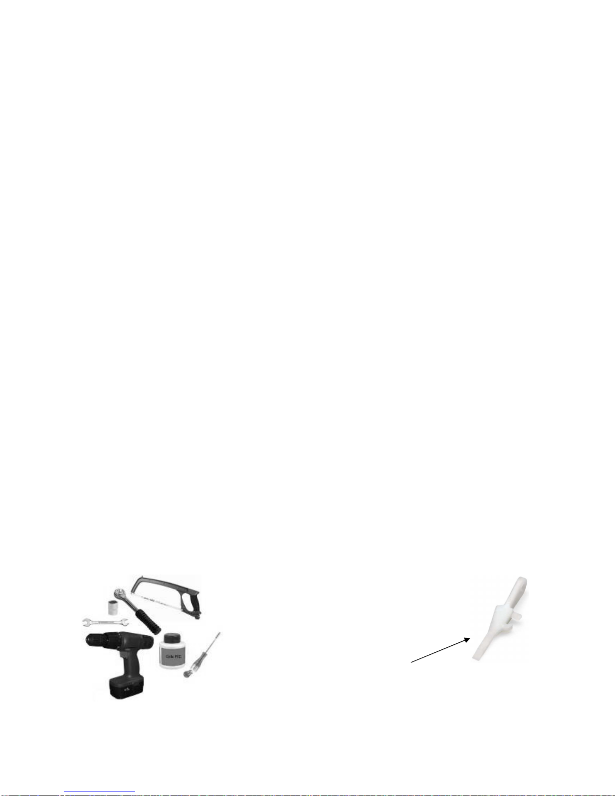
The following tools are needed for installing the Klereo system:
Figure 4. Tools for installation
- A saw
- A drill
- A screwdriver
- A cross-head screwdriver
- A ratchet spanner Ø 13
- PVC glue
- A spanner Ø 13mm
- The special tool to insert wiring cables (
delivered into the
kit)
Klereo Kompact installation manual V 3
7
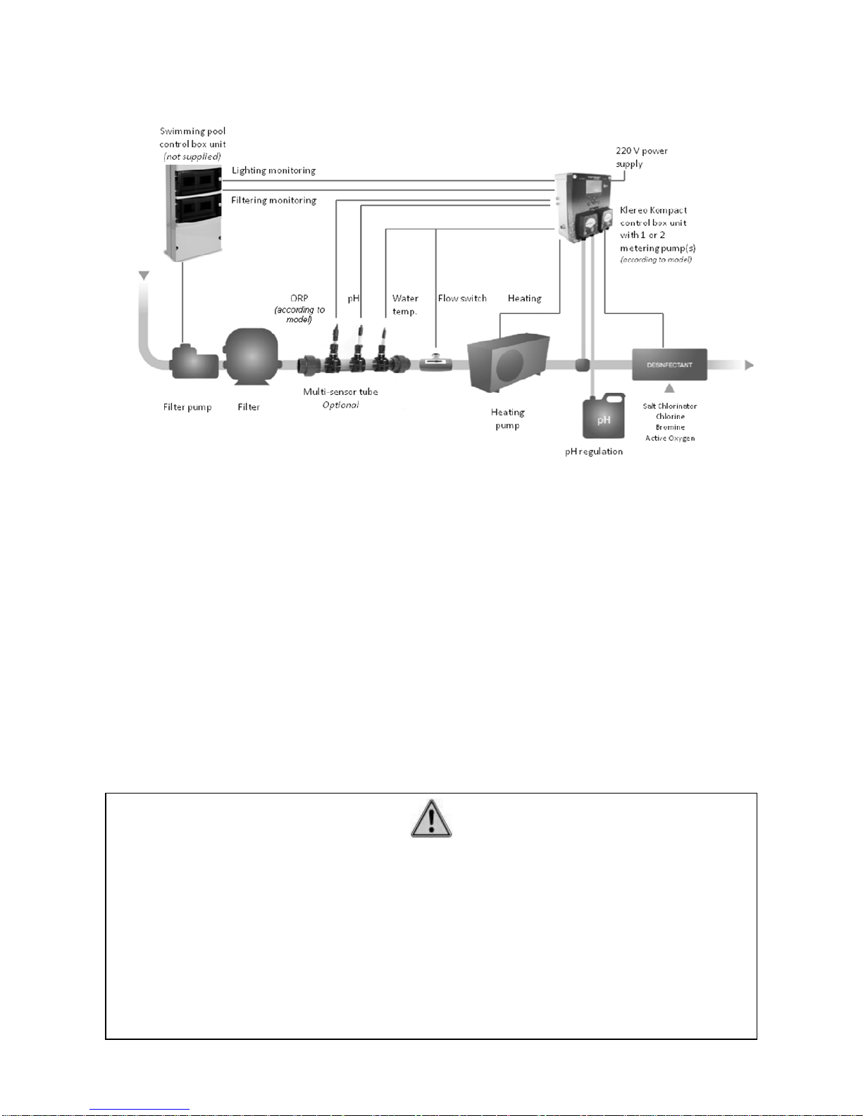
3.2 Installation diagram:
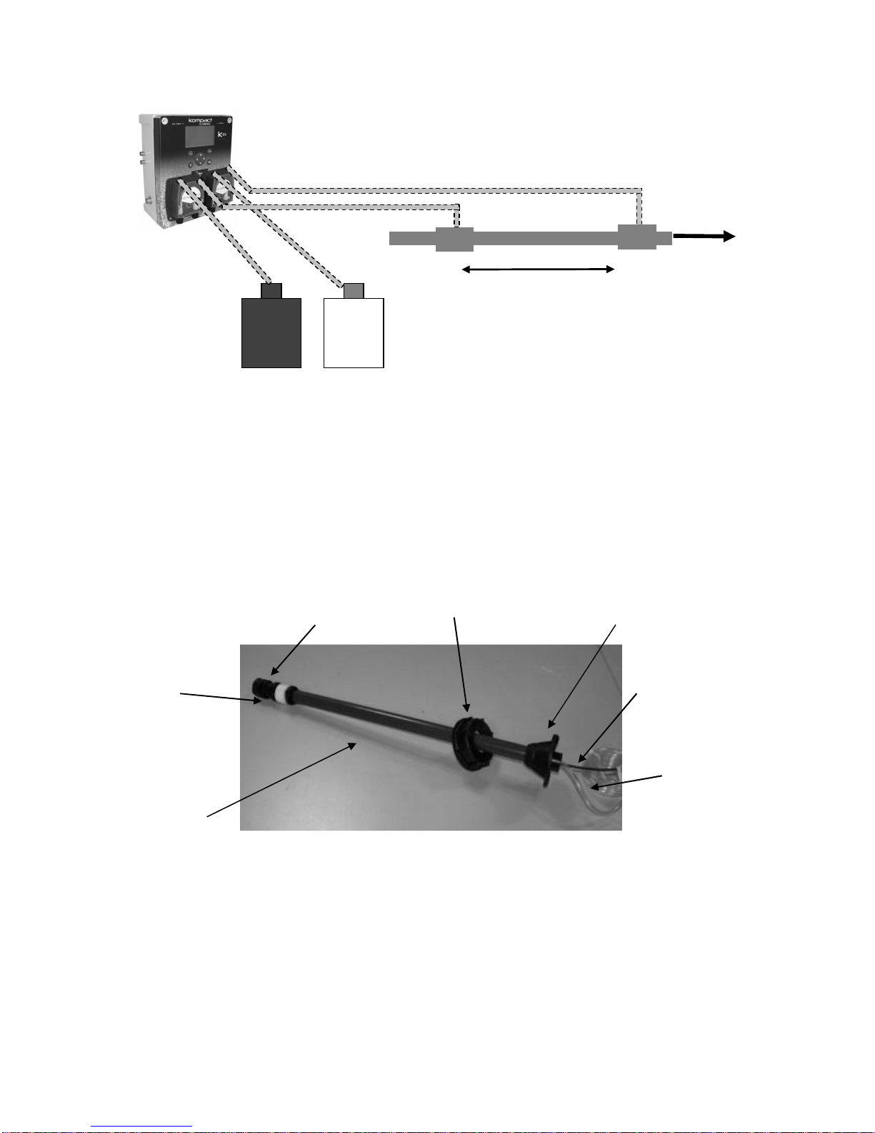
Figure 5. Kompact installation diagram
The flow switch and water temperature sensor as well as pH and ORP probes must be
installed:
o After the filter
o Before the heating system (Heating pump or heat exchanger) as well as before
the water treatment injection points or the Salt Chlorinator cell.
Water treatment injection points and the Salt Chlorinator cell must be located after all pool
control systems and equipments, in the water flow in order not to cause any damage to them.
Accessories to fix the probes and liquid water treatment (pH, liquid Chlorine and active
Oxygen) injections are optional with 4 solutions to select:
• Holding collars for probes and injections
• T shape collar for injections
• A multi-sensor tube for probes
• A chamber of analysis (refer to the specific manual)
for the probes
IMPORTANT
- Maximum distance between the pH and ORP probes must not exceed 20cm
- The probes must not be installed near the 220V cable or the filter pump, to avoid
interference from electromagnetic fields on the measurements (recommended
distance 50 cm).
- Minimum distance between the water treatment injection points must not be less
than 40cm
- We advise to use T shape collars for liquid water treatment injections: pH, liquid
Chlorine or active Oxygen.
Klereo Kompact installation manual V 3
8
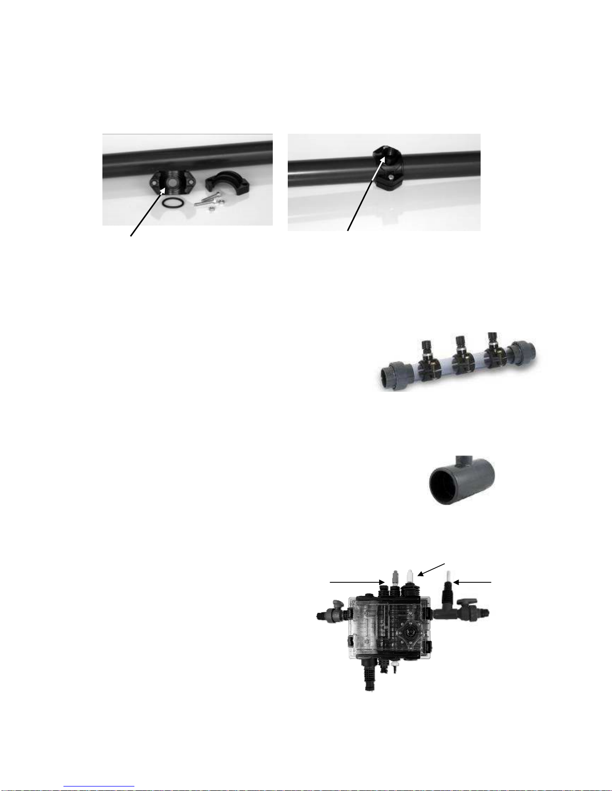
3.3 Hydraulic accessories positioning
3.3.1 Holding collars (optional)
Install the collars directly onto the existing pipe. There are 2 models: Ø 50mm or Ø 63mm.
Probes must be relatively close to each other.
Figure 6. Fitting holding collars
3.3.2 The multi-sensor tube (optional)
Cut the pipe to a length of 440 mm for Ø 50 mm multisensor tubes and 550 mm for Ø 63 mm ones.
If there is an elbow bend on the filter circuit, it must be at
least 10cm from the multi-sensor tube.
Figure 7. Multi-sensor tube
3.3.3 T shape collar (optional)
Cut the pipe to a length of 55 mm for Ø 50 mm T shape collars
and 65 mm for Ø 63 mm ones.
Figure 8. T shape collar
3.3.4 Chamber of analysis (optional)
The chamber (Ref. KL20-A1) is screwed
onto the wall. Read carefully the installation
manual to ensure correct mounting and
probe installation.
ORP probe
pH probe
Water
temperature
sensor
Drill a 13mm hole for the probes
and a 8mm one for the injections
Put the seal into place
Klereo Kompact installation manual V 3
9
Figure 9. Positioning the probes in the chamber of analysis
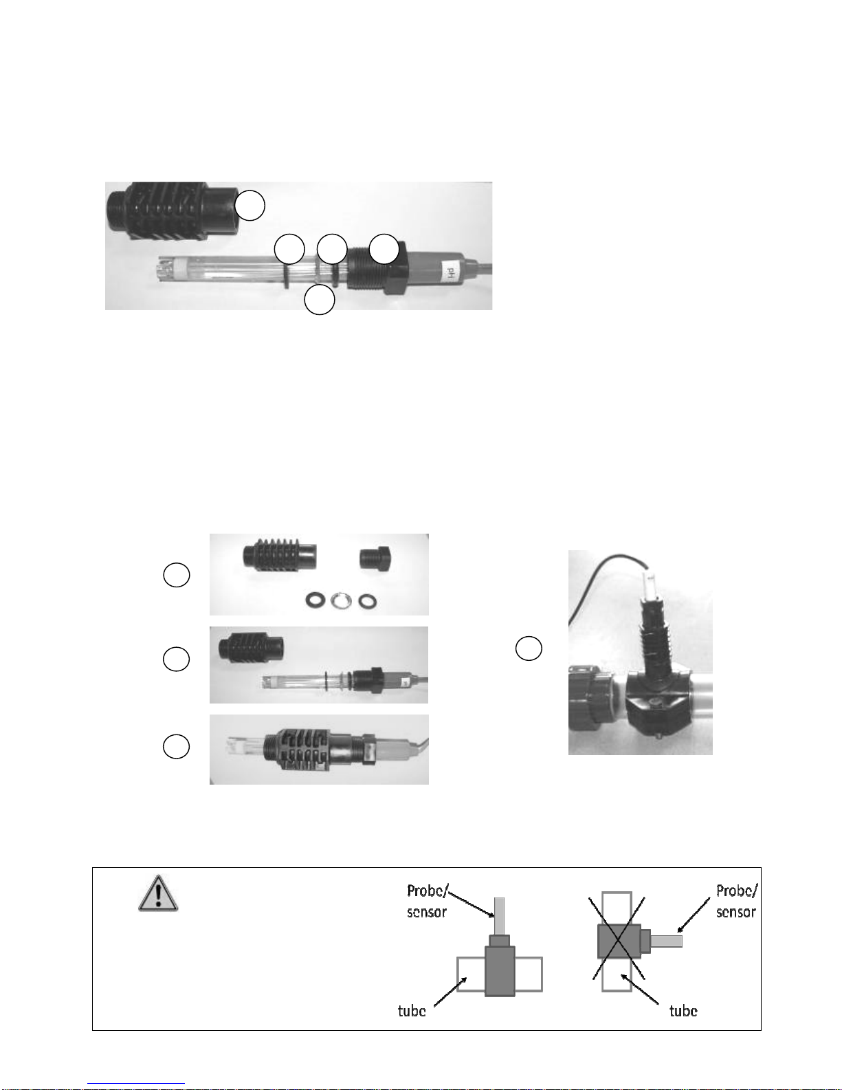
3.4 Fixing the probes.
The necessary parts to fix the pH, ORP probes and water temperature sensor are detailed as
follows:
Figure 10. Fixing parts
The following procedure should be used when inserting the probes into the holders. Do not
force them into place but rather:
1. Unscrew the probe holder, and remove the metal and rubber washers.
2. Then thread on the top of the probe holder and the washers one after another
3. Slide on the body of the probe holder
4. Screw it up so it is fixed at the top of the probe (using Teflon tape to seal them). The
end of the probes is fragile, adjust the height of the probe so that it does not touch the
bottom of the plastic tube (1 to 2 cm space clear)
Taps are delivered together with the multi-sensor tube and are to be screwed onto the
unused holding collars.
Figure 11. Assembly of probe-holders and water temperature sensor
IMPORTANT
The holding collars must be placed so that
the pH and ORP probes are held vertically
(+/- 10°) with or without the multi-sensor tube.
2
1
3
4
a : probe-holder upper part
b : rubber washer
c : metal washer
d : flat rubber washer
e : probe-holder body
a b
c
d
e
Klereo Kompact installation manual V 3
10
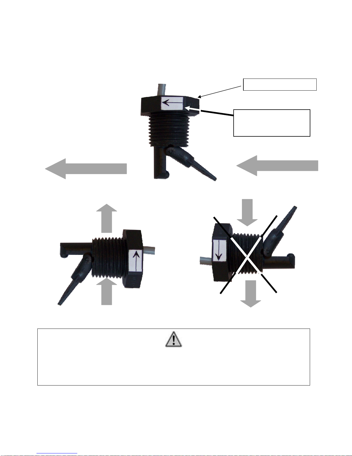
3.5 Installing the flow switch
The flow switch sensor is factory delivered together with a Ø 50mm T shape collar for
mounting. To fix it, cut the pipe to a length of 30 mm. It is very important to respect the right
direction by checking the arrow representing the water stream flow.
Figure 12. Flow switch sensor on Ø 50mm T shape collar on horizontal pipe
Figure 13. Flow switch sensor on Ø 50mm T shape collar on vertical pipe
For Ø 63mm, specify when ordering (the flow switch and T shape collar are specicifc). Screw
the water flow switch in such a way that the sensor is correctly positioned in relation with the
water stream flow (contact open when the water is not circulating).
Flow switch sensor
Respect the arrow
direction on the flow
switch
IMPORTANT : Respect the arrow direction from bottom to top.
It is not possible to position the T shape collar in downward water stream flow
Always use the delivered T shape collar for the flow switch

Klereo Kompact installation manual V 3
11
3.6 Connecting the pipes of the metering pumps
Figure 14. Metering pump kit presentation
Insert both pipes onto the metering pump (check the arrows showing the direction of input of
the water treatment products)
Figure 15. Mounting metering pumps (see manual for metering pump)
Put the rigid, semi-opaque pipe (PE) onto the injector valve, then screw it to the reducer ½ 3/8 that will be screwed onto the holding collar (apply Teflon tape to seal).
Figure 16. Mounting injector valve
Apply Teflon tape to seal
Check direction
of the arrow
Insert the transparent
flexible pipe (PVC)
from the tank
Insert the rigid semiopaque pipe (PE) for
connection to the
injector valve
Tighten the
2 nuts
Arrows showing
direction of input
of the products
Transparent
flexible
pipe (PVC)
Rigide semiopaque pipe
(PE)
Injector valve
Drawing strainer
Reducer ½ - 3/8
Klereo Kompact installation manual V 3
12
To mount the transparent flexible pipe onto the drawing strainer, proceed as follows:
Strainer
Transparent flexible pipe
Remove the strainer nut
Insert the pipe into the nut
Insert the transparent flexible pipe
onto the strainer
Screw the nut (put Teflon tape to seal)
Figure 17. Mounting the drawing strainer
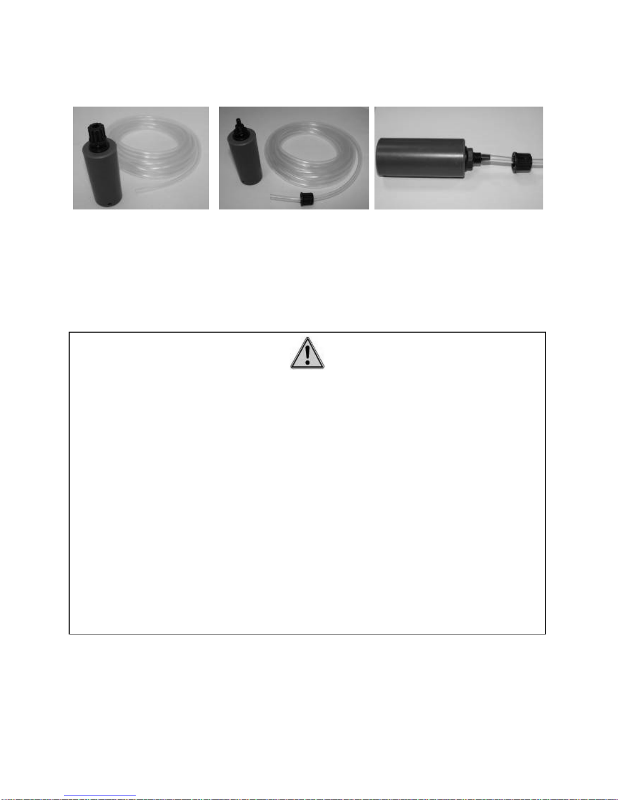
3.7 Installing the water treatment tanks and injections
IMPORTANT:
Never mix the chemical products. Use normal protective wear (gloves, face mask and
eye protectors) to handle tanks of chemical products.
Check that the holding collars used to inject the products are sealed. The room must
be ventilated. Keep a minimum distance of 1 m between the tanks and the Klereo
components, to avoid fumes from the products damaging the system.
When changing a tank, handle carefully the tube or the cane. Do not force on the
strainer and the empty tank level detector at the end of the cane (when using a
drawing cane with empty tank level detector: optional).
Use sodium hypochlorite in liquid form as disinfectant, sulfuric acid to reduce pH
and caustic soda (sodium hydroxide) to increase pH.
When making installation or when replacing a tank, check that the chlorine injection
pump is connected to the liquid chlorine tank, and the same for the pH reduction or
pH increase product injection pump.
Put each tank into a drip tub to avoid mixing chemical products in case of leaks.
Klereo Kompact installation manual V 3
13
Figure 18. Mounting the metering pumps and empty tanks detectors
The holding collars used for injecting products must be placed at the end of the filtering circuit
before the backflow.
Maximum distances between Klereo control box unit and the tanks or the injection points are
2m maximum.
Minimum distance between 2 injection points is 40cm.
A drawing up cane with empty tank level detector is optional.
Figure 19. Drawing up cane with empty tank level detector
When installing the tank empty detectors, first drill a 32mm diameter hole into the plug of the
disinfectant tank. Slide the plug from the bottom of the cane, drill 2 holes onto the plug to
match the 2 holes onto the conical black collar and screw it onto the plug. Then screw the
plug onto the tank.
Wire connected
to the control
box unit
Transparent
flexible pipe
connected to
metering pump
Tank plug
Tube
Strainer
Empty tank
level detector
Conical black collar
pH-
or
pH+
Liquid Chlorine
or
active Oxygen
40 cm
min.
Backflow
Klereo Kompact installation manual V 3
14
Drilled tank plug
Plug fixed onto the cane
with 2 little screws
Cane screwed to the tank
Figure 20. Mounting the drawing up cane
3.8 Installing the solenoid valve for Kompact with Bromine or Chlorine
tablets
The Kompact for Bromine regulates disinfection by opening a solenoid valve letting the water
going through a brominator filled with bromine or a chlorinator filled with Chlorine tablets.
There are 2 possibilities to install the Bromine regulation kit.
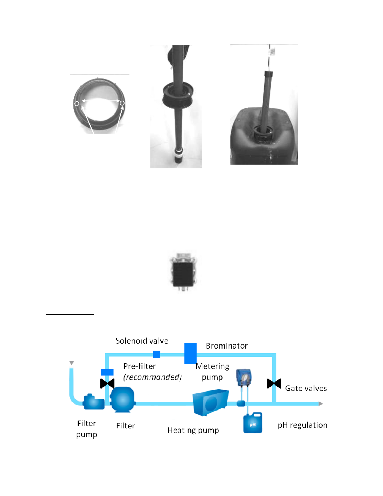
Figure 21. Solenoid valve.
First possibility:
In order to avoid the valve clogging, install a by-pass after the filter and before the backflow
as shown on the diagram below.
Figure 22. First possibility for installing the Bromine regulation kit
32mm
2 lithe holes to
insert fixing screws
Respect the direction
identified by the arrow on
the brass body
Klereo Kompact installation manual V 3
15
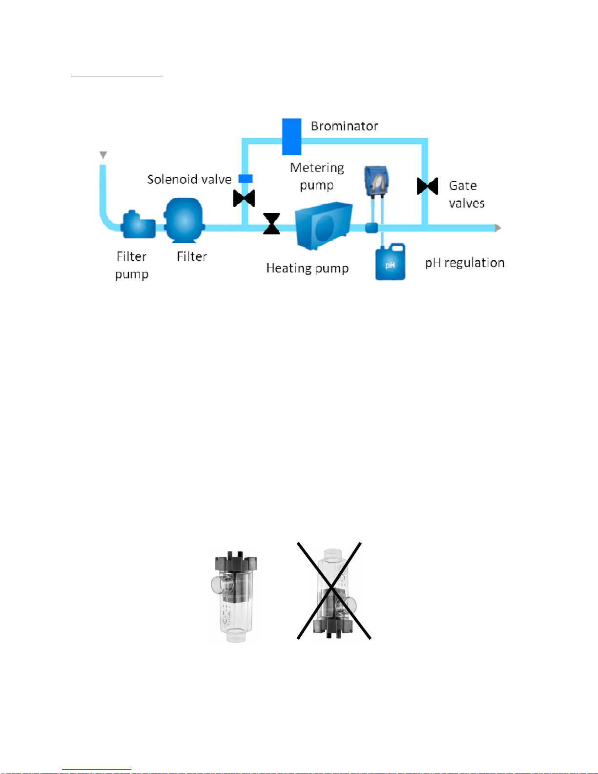
Second possibility:
In case of low water flow rate, position the by-pass entrance between the pump and the filter.
Add a primary filter to avoid the valve clogging.
Figure 23. Second possibility for installing the Bromine regulation kit
Connecting the solenoid valve is done in Ø 32mm. Use unions in case of pipes Ø 50 or
63mm. Hydraulic kits for Bromine are optional:
– KL20-KH50: 2 collars 3/4" Ø 50mm and 4 unions ¾ Ø32mm
– KL20-KH63: 2 collars 3/4" Ø 63mm and 4 unions ¾ Ø32mm
The brominator tap adjusting the water flow must be fully opened (refer to the Brominator
manual).
Install manual valves at the by-pass level for easy maintenance.
3.9 Installing the cell with Klereo Salt Chlorinator
The cell is supplied together with the Salt Chlorinator control box unit in a separate parcel.
Allow a maximum distance of 1.5m between the cell and the control box unit (it is actually the
length of the cable between the 2 units). Connecting the cell is done in Ø 50mm. Thanks to
respect the following recommendation:
• The cell must be installed vertically for maximum efficiency.
• The cell is installed after filtration and heating system but before the backflow.
• For easy maintenance, the cell can be installed on a by-pass as shown below:
 Loading...