


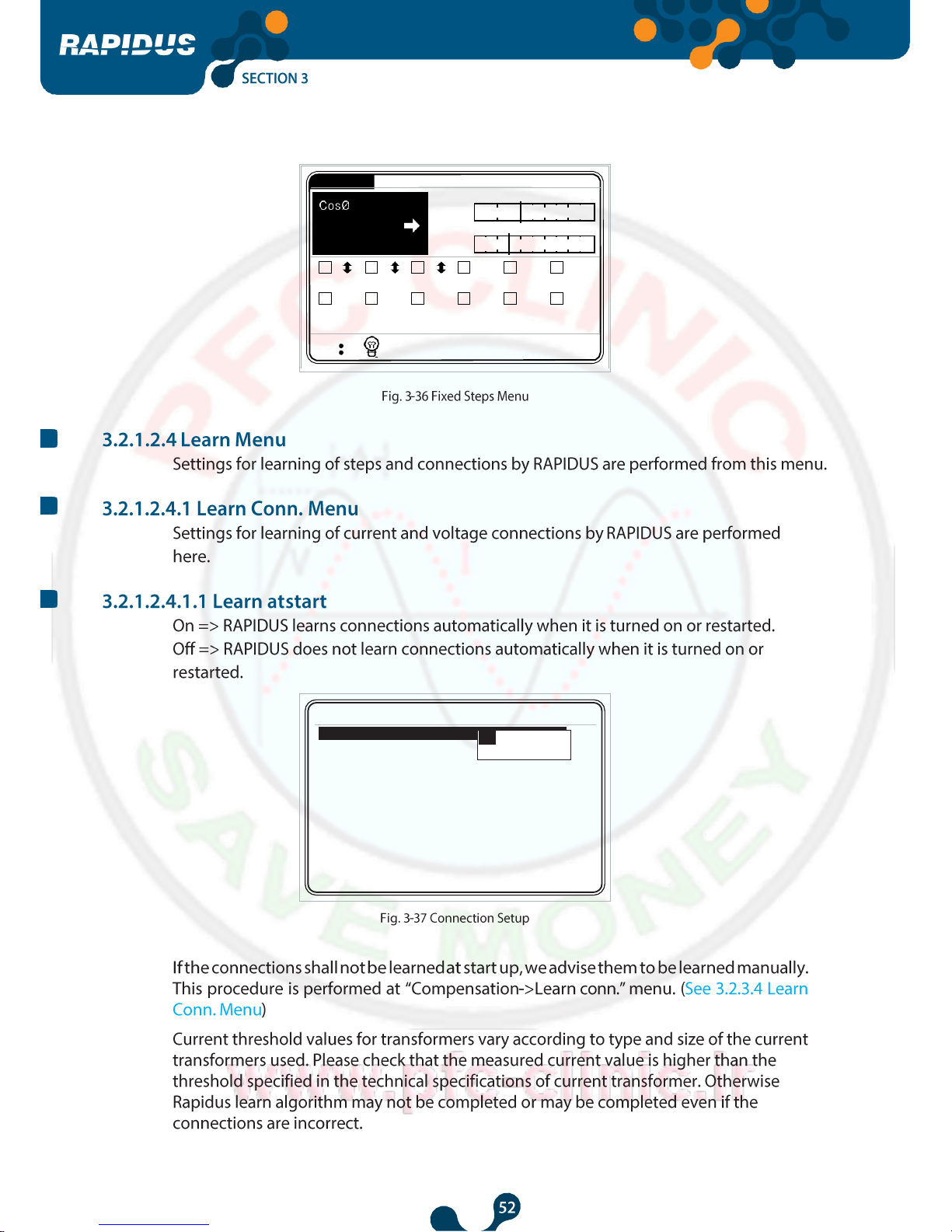
Power Factor Controller
Power Factor
Controller
USER
MANUAL
Power Factor Controller
Power Factor Controller
Power Factor Controller
Power Factor Controller
Power Factor Controller
Power Factor Controller
Power Factor Controller

Power Factor Controller
Power Factor
Controller
Power Factor Controller

Power Factor Controller
Power Factor Controller

Power Factor Controller
Power Factor Controller
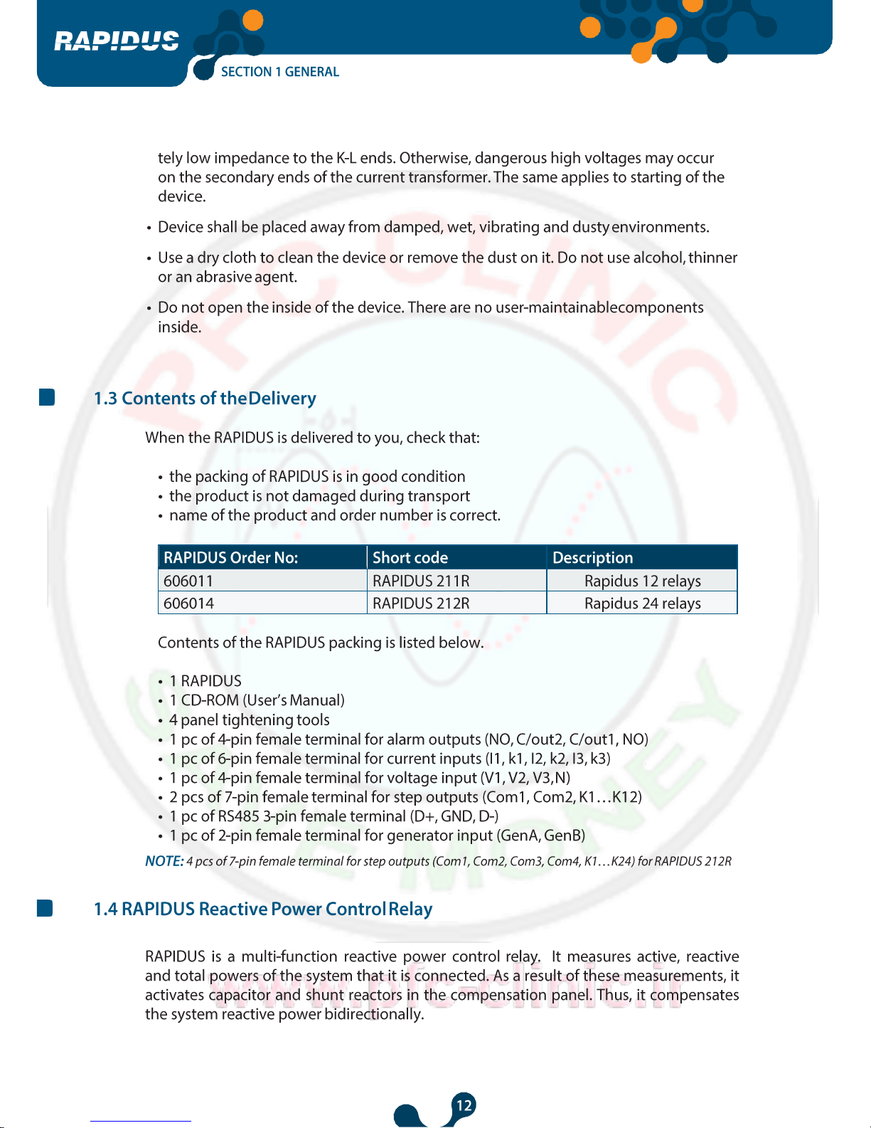
1
2
3
4
Settings
Measure
1.000
Comp. Alarms
Analysis
Qind/P
5
W
1.350
0 50
VAr
1
Qcap/P
0
%
6
1 2
10
V (L-N)
I
17 : 2 2
11 12 13 14 15 16
17
0
%
7
1 2 3 4 5 6
10.0
10.0
10.0
10.0
10.0
10.0
8
c c c c c c
7 8 9 10
11
12
9
10.0
c
10.0
c
10.0
c
10.0
c
10.0
c
10.0
c
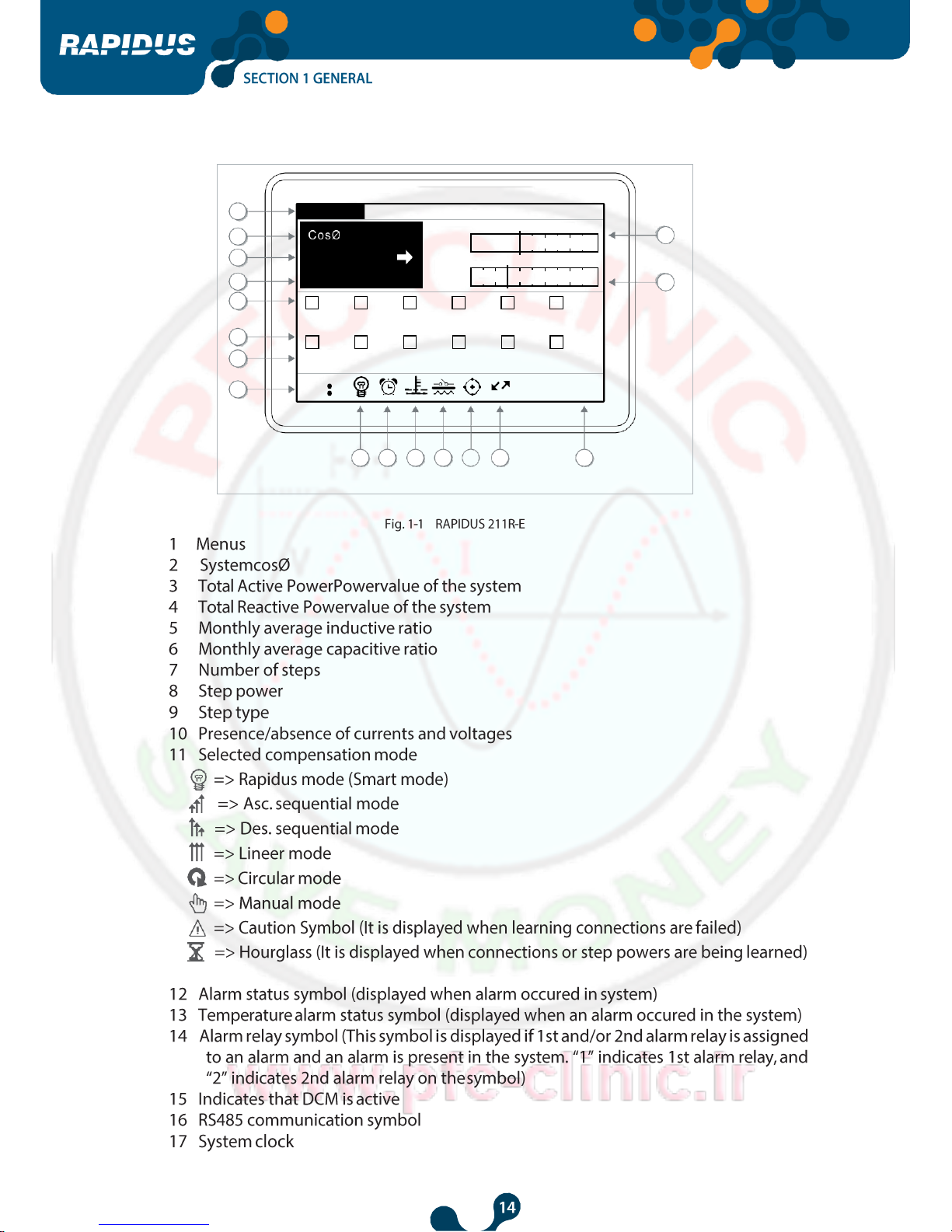
Power Factor Controller
14
13
9 10 11 12
17 : 2 2
6
0
%
Qcap/P
50 0
1.350
1
W
VAr
5
Qind/P
Alarms Analysis
Comp.
Settings Measure
1.000
1
2
3
4
0
%
7
1 2 3 4 5 6
7 8 9 10
11
12
1 2 3 4 5 6
7 8 9 10
11
12
8
1 2
V (L-N)
I
Power Factor Controller
17 : 2 2
1 2
V (L-N)
I
7 8 9 10 11 12
1 2 3 4 5 6
7 8 9 10 11 12
6 5 4 3 2
0
%
50
0
%
Qcap/P
0
W
VAr
1
Comp. Alarms
Analysis
Qind/P
Measure
1.000
1.350
1
Settings
17 : 2 2
1 2
C
10.00k VAr
0
0
Type
Power
Switch
Time
V (L-N)
I
Number 1
0
%
50
0
%
Qcap/P
0
W
VAr
Comp. Alarms Analysis
Qind/P
Measure
1.000
1.350
1
Settings
Power Factor Controller
Meters
Imp. Active &
Cap. Reactive
Meters
Exp. Active &
Cap. Reactive
=> capacitive
=> positive
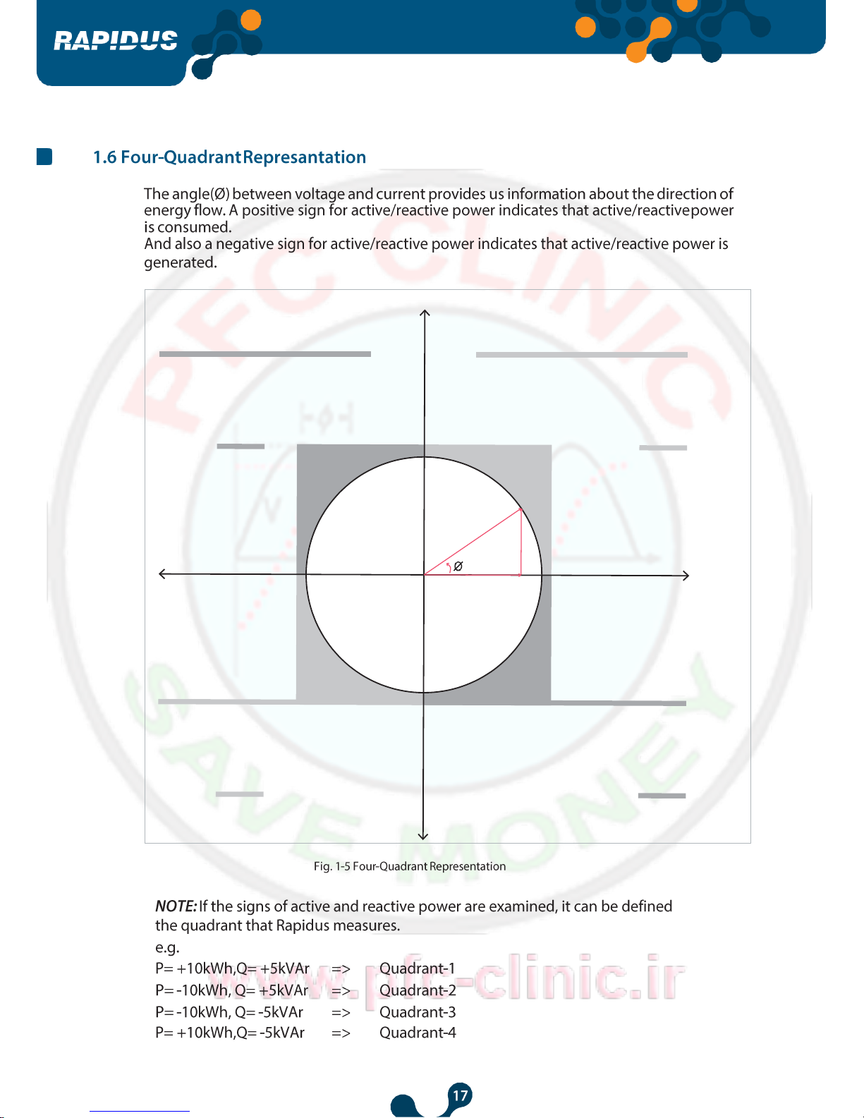
CosØ
PF
QUADRANT
-4
P => positive
Q
=> negative & capacitive
=> negative
=> negative & inductive
=> inductive
=> negative
P
Q
CosØ
PF
QUADRANT
-3
Active Power
P
Q S
Meters
Imp. Active &
Ind. Reactive
Meters
Exp. Active &
Ind. Reactive
=> positive
PF
CosØ => inductive
CosØ => capacitive
PF => negative
QUADRANT
-1
P => positive
Q
=> positive & inductive
=> negative
=> positive & capacitive
P
Q
QUADRANT
-2
Reactive Power

Power Factor Controller
Power Factor
Controller
Power Factor Controller
Power Factor Controller
Power Factor Controller
Power Factor Controller

Power Factor Controller

Power Factor Controller
Power Factor
Controller

Power Factor Controller
çe
ugust2013
5:13
Açılış Ayarları / Startup Settings / настройки
Dil / Language English
Date 30 August 2014
Time 17:25:29
CTR 1
VTR 1.0
Connection Phase-Neutral
Step number 1
Start
17:2
P
yccKvıı
1
1.0
Phase-Neutral
1
30 A
English
Türk
Türkçe
Date
Time
CTR
VTR
Connection
Step number
Start
Açılış Ayarları / Startup Settings / настройки
Dil / Language
Power Factor Controller
7
6
5
4
3
2
1
Tarih 30 August 2014
Date 30 August 2014
Date 30 August 2013
Date 30 August 2013
Date 30 July 2013
Date 30 July 2013
Date 29 July 2013
Açılış Ayarları / Startup Settings / настройки
Dil / Language English
Time 17:25:29
CTR 1
VTR 1.0
Connection Phase-Neutral
Step number 1
Start
Date 30 August 2014
Power Factor Controller
gust2013
:13
Açılış Ayarları / Startup Settings / настройки
Date
30 Au
Dil / Language English
1
Time 17:25
1 2 3
4
CTR 1
VTR 1.0
5 6 7
8
Connection Phas
9 0 .
-
Step number 1
Start
Low li
1
High
5000
ok
mit
clr
Power Factor Controller
1 2 3
4
1
2
5
6
Açılış Ayarları / Startup Settings / настройки
Dil / Language English
Date 30 August 2014
Time 17:26:33
CTR 20
VTR 1.0
Step number 1
Start
1
1 2 3
4
5 6 7
8
9 0 .
-
ok clr
Low limit
1
High limit
5000
1
1 2 3
4
5 6 7
8
9 0 .
-
ok clr
Low limit
1
High limit
5000
2
1 2 3
4
5 6 7
8
9 0 .
-
ok clr
Low limit
1
High limit
5000
2
1 2 3
4
5 6 7
8
9 0 .
-
ok clr
Low limit
1
High limit
5000
20
1 2 3
4
5 6 7
8
9 0 .
-
ok clr
Low limit
1
High limit
5000
20
1 2 3
4
5 6 7
8
9 0 .
-
ok
clr
Low limit
1
High limit
5000

Power Factor Controller
gust 2013
:13
Açılış Ayarları / Startup Settings / настройки
Dil / Language
Date
Time
CTR
English
1
30 Au
21:24
20
Connection
Step number
Start
Phas
1
1 2 3
4
5 6 7
8
9 0 .
-
Low li
1.0
High
5000.
ok
mit
0
clr
1
Step number
Start
Açılış Ayarları / Startup Settings / настройки
Dil / Language English
Date 30 August 2013
Time 17:26:29
CTR 20
VTR 1.0
Power Factor Controller
gust 2013
:13
Açılış Ayarları / Startup Settings / настройки
Dil / Language
Date
Time
CTR
VTR
Connection
Step number
Start
30 Au
17:26
20
1.0
Phas
1
English
1
Low limit
1
High limit
12
1 2 3
4
5 6 7
8
9 0 .
-
ok
clr
Açılış Ayarları / Startup Settings / настройки
Dil / Language English
Date 30 August 2014
Time 21:24:13
CTR 20
VTR 1.0
Connection Phase-Neutral
Step number 1
Start
Initializing ..........................

Power Factor Controller
CosØ1 1.000
Qind/P 0
%
CosØ2 1.000
0 5c
CosØ3 1.000
Qcap/P 0
%
Settings Measure Comp. Alarms
Analysis
W
VAr
1. 000
1. 350
1
Qind/P
0
Qcap/P
50
0
%
0
%
1 2 3 4 5 6
10.0
10.0
10.0
10.0
10.0
10.0 c c c c c c
7 8 9 10
11
12
10.0
10.0
10.0
10.0
10.0
10.0
c c c c c c
V (L-N)
I
1 7 : 2 9
17:27
V (L-N)
I
6
10.0
c
12
10.0
c
5
10.0
c
11
10.0
c
4
10.0
c
10
10.0
c
3
10.0
c
9
10.0
c
2
10.0
c
8
10.0
c
1
10.0
c
7
10.0
c
RAPIDUS is learning connections.
Please wait...
Retry count : 1
Analysis
Alarms
Measure Comp.
Settings
Power Factor Controller
Settings
Measure Comp. Alarms
Analysis
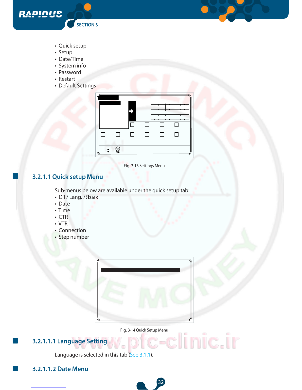
Quick setup
Setup
Date / Time
System info
Password
Restart
Default settings
Qind/P
0
Qcap/P
50
0
%
3
10.0
4
10.0
5
10.0
6
10.0
0
%
c c c c c c
7 8 9 10
11
12
10.0
10.0
10.0
10.0
10.0
10.0
c c c c c c
V (L-N)
I
1 7 : 2 9
Settings->Quick setup
Dil / Language English
Date 30 August 2014
Time 17:30.13
CTR 1
VTR 1.0
Connection Phase-Neutral
Step number 1

Power Factor Controller
OK
X
Settings changed.
Save?
Power Factor Controller
P 1326
Q
4.
S 1326
1 2
10.0 10.0
.4 W
2 VAr
.4 VA
3 4
10.0 10.0
c c
9 10
17:30
V
I
1 2 3
6
10.0
c
12
10.0
c
5
10.0
c
11
10.0
c
Clear
10.0 10.0
c c
Communication
Alarm
c
8
10.0
c
c
7
10.0
c
dk
1
1.0
Phase-Neutral
15
Device
Default settings
Energy
Restart
CTR
VTR
Connection
Demand period
0
%
50
0
%
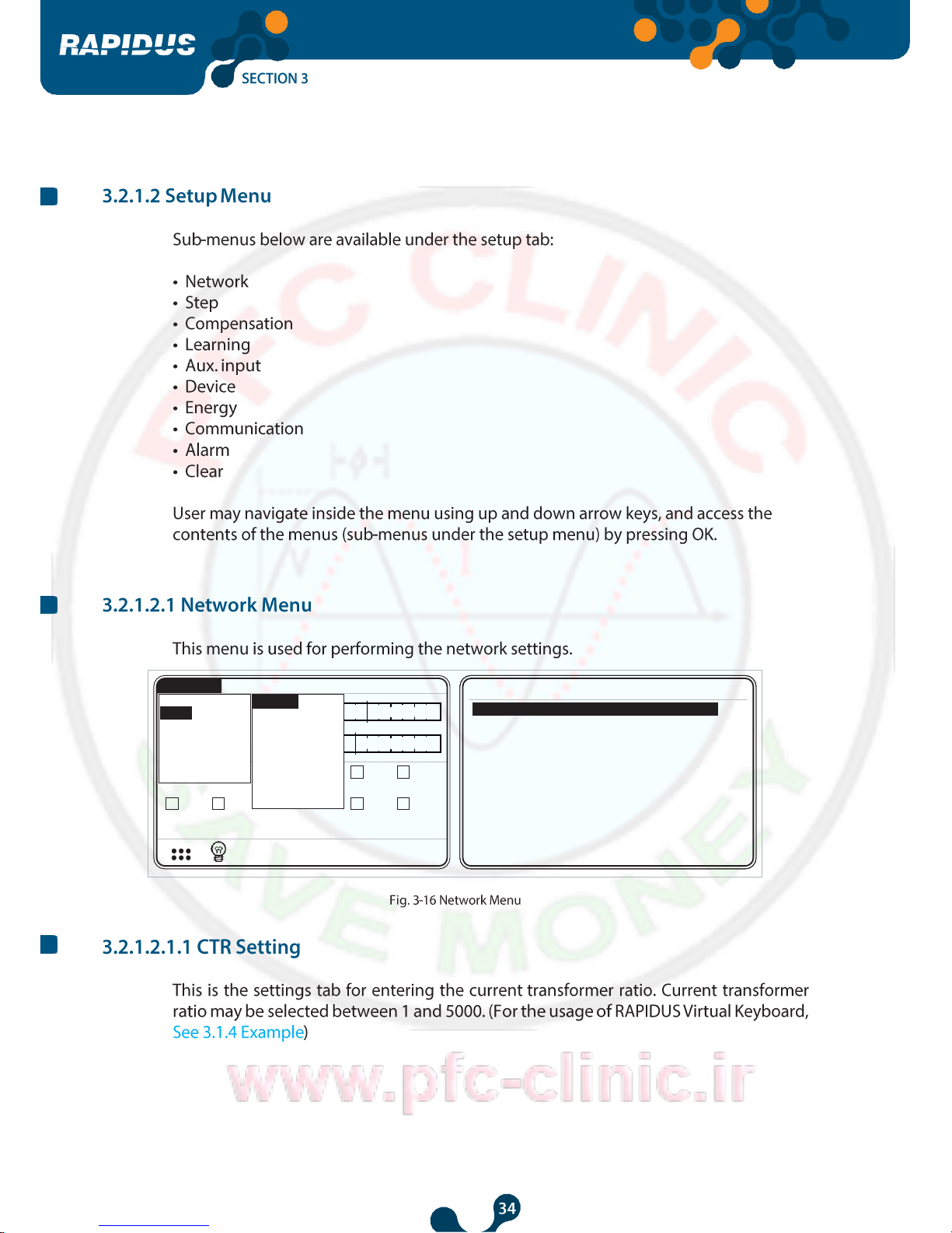
Settings->Setup->Network
Network
Steps
Compensation
Learn
Aux. input
Quick setup
Setup
Date / Time
System info
Password
Analysis
Alarms
Measure Comp.
Settings
Power Factor Controller
dk
dk
dk
dk
Settings->Setup->Network
CTR 1
VTR 1.0
Connection Phas
Demand period 15
Settings->Setup->Network
CTR 1
VTR 1.0
Connection Phas
Demand period 15
1
1 2 3
4
5 6 7
8
9 0 .
-
ok
clr
Low li
1
High
5000.
mit
0
1
1 2 3
4
5 6 7
8
9 0 .
-
ok
clr
Low li
1
High
5000.
mit
0
Power Factor Controller
dk
dk
P 1326
Q
4.
S 1326
1 2
10.0 10.0
8.9
0
A
%
257.1
V
50
.4 W I
2 VAr V
.4 VA
3 4
10.0 10.0
c c
9 10
ok clr
Low limit
1
High limit
60
1 2 3 4
5 6 7 8
9 0 . -
1
1
1.0
Phas
15
CTR
VTR
Connection
Demand period
Settings->Setup->Network
17:32
V (L-N)
I
6
10.0
c
12
10.0
c
5
10.0
c
11
10.0
c
10.0
c
Clear
10.0
c
c
8
10.0
c
c
7
10.0
c
Energy
Default settings
Communication
Alarm
Restart
0
%
Ent. power
Ent. type
Predefined
Other
Network
Compensation
Learn
Aux. input
Device
Quick setup
Setup
Date / Time
System info
Password
Analysis
Alarms
Measure Comp.
Settings

Power Factor Controller
10.00
Low limit
10.00
0.00
10.00
High limit
10.00
1000.00
ok clr
10.00
2 3 4
6 7 8
0 . -
1
5
9
10.00
10.00
10.00
10.00
10.00
10.00
10.00
10.00
Step 2
Step 3
Step4
Step 5
Step 6
Step 7
Step 8
Step 9
Step 10
Step 11
Step 12
Settings->Setup->Steps->Ent. power
Step 1
C
L
C
C
C
C
C
C
C
C
C
C
C
C
Step 1
Step 2
Step 3
Step 4
Step 5
Step 6
Step 7
Step 8
Step 9
Step 10
Step 11
Step 12
Settings->Setup->Steps->Ent. type
Power Factor Controller
1
Settings->Setup->Steps->Predefined
Structure
Power
Count
10.00
12
1 - 1 - 1 -
1 - 1 - 1 - 1
1 - 1 - 2 - 2
1 - 2 - 2 - 4
1 - 2 - 3 - 3
1 - 2 - 4 - 4
1 - 1 - 2 - 4
1 - 2 - 3 - 4
1 - 2 - 4 - 8
1 - 1 - 2 - 3

Power Factor Controller
Settings->Setup->Steps->Other
15
1 2 3
4
5 6 7
8
9 0 .
-
ok
clr
Low li
3
High
1000
mit
Settings->Setup->Compensation
Steps
Program
Target 1
Target 2
Target low lim.
Target high lim.
Activation time
Deactivation time
Shift angle
Averaging time
Fixed steps
Entered
Rapidus
1.000
0.900
0.002
0.002
10
10
0.00
Off
None
sec.
sec.

Power Factor Controller
Power Factor Controller
Settings->Setup->Compensation
Steps Entered
Program
Rapidus
Target 1 1.000
Target 2 0.900
Target low lim. 0.002
Rapidus
Asc. sequential
Des. sequential
Linear
Circular
Manual
Target high lim. 0.002
Activation time 10 sec.
Deactivation time 10 sec.
Shift angle 0.00
Averaging time Off
Fixed steps None
Demand
B C C C C C
A
CosPhi = 0.950 (Target inductive)
CosPhi = 1.000
CosPhi = 0.900 (Target capacitive)

Power Factor Controller
INDUCTOR
CAPACITOR
FIXED
DEAD
ALL STEPS TO BE USED
STEPS TO BE USED IN COMPENSATION
EXAMPLE: SYSTEM INDUCTIVE, 46K CAPACITOR DEMAND AVAILABLE (Minimum step power 5K * CK = 5K * 2/3 = 3.3K)
SYSTEM CAPACITIVE, 100K INDUCTOR DEMAND AVAILABLE
Compensation is ended as demand is 1K and lower than CK.
Step 1
Step 2
Step 3
Step 4
Step 5
Demand is -35K and higher than CK, however demand is continued although
all activated capacitors are deactivated and all inductors are activated.
AN ALARM WILL BE GIVEN.
Step 1
Step 2
Step 3
Step 4
Step 5
3(5)
10K
4(7)
5K
1(3)
10K 1 5K
Demand
-90K
Demand 41K
2(4)
10K
2
10K
5(8)
15K
3(5)
10K
3(5)
10K
3
10K
Demand
-75K
Demand 31K 7(11)
20K
5(8)
15K
4(7)
5K
4
10K
Demand
-55K
Demand 16K
1(3)
10K
7(11)
20K
5(8)
15K
5
10K
Demand
-45K
Demand
-4K
6(10)
25K
6
0K
2(4)
10K
4(7)
5K
7(11)
20K
7
5K
8(12)
30K
8
15K
9
0K
10
25K
11
20K
12
30K

Power Factor Controller
INDUCTOR
CAPACITOR
FIXED
DEAD
ALL STEPS TO BE USED
STEPS TO BE USED IN COMPENSATION
Example: Demand 46K (inductive) (Minimum step power 5K * CK = 5K * 2/3 = 3.3K)
Demand 100K (Capacitive)
Compensation is ended as demand is 1K and lower than CK.
Step 1 Step 2 Step 3
Demand is -35K and higher than CK, however demand is continued although
all activated capacitors are deactivated and all inductors are activated.
AN ALARM WILL BE GIVEN.
Step 1 Step 2 Step 3 Step 4 Step 5
1(3)
10K
1
5K
8(12)
30K
8(12)
30K
Demand
-70K
Demand 16K
2(4)
10K
2
10K
3(5)
10K
3(5)
10K
3(5)
10K
3
10K
Demand
-60K
Demand 6K
5(8)
15K
5(8)
15K
4(7)
5K
4
10K
Demand
-55K
Demand 1K
1(3)
10K
5(8)
15K
5
10K
Demand
-45K
6(10)
25K
6
0K
2(4)
10K
7(11)
20K
7
5K 8(12)
30K
8
15K
9
0K
10
25K
11
20K
12
30K

Power Factor Controller
Power Factor Controller
INDUCTOR
CAPACITOR
FIXED
DEAD
ALL STEPS TO BE USED
STEPS TO BE USED IN COMPENSATION
Example: SYSTEM INDUCTIVE, 46K CAPACITOR DEMAND AVAILABLE (Minimum step power 10K * CK = 10K * 2/3 = 6.7K)
SYSTEM CAPACITIVE, 20K INDUCTOR DEMAND AVAILABLE
SYSTEM CAPACITIVE, 40K INDUCTOR DEMAND AVAILABLE
SYSTEM CAPACITIVE, 20K INDUCTOR DEMAND AVAILABLE
Compensation is ended as demand is -4K and lower than CK.
Step 1
Compensation is ended as demand is 0K and lower than CK.
Step 1
Compensation is ended as demand is 0K and lower than CK.
Step 1
Compensation Demand is continued as demand is -10K and higher than CK.
However, there are no inductors to activate nor capacitors to deactivate.
AN ALARM WILL BE GIVEN.
Step 1
1(3)
10K
1
10K
5(8)
10K
5(8)
10K
7(11)
10K
3(5)
10K
2(4)
10K
2
10K
4(7)
10K
6(10)
10K
4(7)
10K
3(5)
10K
3
10K
5(8)
10K
3(5)
10K
4(7)
10K
4
10K
6(10)
10K
5(8)
10K
5
10K
1(3)
10K
6(10)
10K
6
0K
7(11)
10K
7(11)
10K
7
10K
8(12)
10K
8
10K
9
0K
10
10K
11
10K
12
10K

Power Factor Controller
Power Factor Controller
INDUCTOR
CAPACITOR
FIXED
DEAD
ALL STEPS TO BE USED
STEPS TO BE USED IN COMPENSATION
Example: SYSTEM INDUCTIVE, 46K CAPACITOR DEMAND AVAILABLE (Minimum step power 10K * CK = 10K * 2/3 = 6.7K)
SYSTEM CAPACITIVE, 30K INDUCTOR DEMAND AVAILABLE
SYSTEM INDUCTIVE, 20K CAPACITOR DEMAND AVAILABLE
SYSTEM CAPACITIVE, 60K INDUCTOR DEMAND AVAILABLE
SYSTEM INDUCTIVE, 90K CAPACITOR DEMAND AVAILABLE
Compensation is ended as demand is -4K and lower than CK.
Step 1
Compensation is ended as demand is 0K and lower than CK.
Step 1
Compensation is ended as demand is 0K and lower than CK.
Step 1
Compensation is ended as demand is 0K and lower than CK.
Step 1
Demand is -10K, however, there are no inductors to activate nor
capacitors to deactivate although the demand is continued.
AN ALARM WILL BE GIVEN.
Step 1
1(3)
10K
1
10K
1(3)
10K
6(10)
10K
8(12)
10K
3(5)
10K
3(5)
10K
2(4)
10K
2(4)
10K
2
10K
7(11)
10K
3(5)
10K
4(7)
10K
4(7)
10K
3(5)
10K
3
10K
4(7)
10K
8(12)
10K
5(8)
10K
5(8)
10K
5(8)
10K
4(7)
10K
4
10K
3(5)
10K
6(10)
10K
6(10)
10K
5(8)
10K
5
10K
1(3)
10K
7(11)
10K
6(10)
10K
6
0K
2(4)
10K
7(11)
10K
8(12)
10K
7(11)
10K
7
10K
3(5)
10K
8(12)
10K
8
10K
9
0K
10
10K
11
10K
12
10K
Power Factor Controller
Settings Measure Comp. Alarms
Analysis
W
VAr
1.000
1.350
1
Qind/P
0
Qcap/P
50
0
%
V (L-N)
I
17:34
0
%
17:36
V (L-N)
I
0
%
50
0
%
Qcap/P
Settings Measure Comp. Alarms Analysis
Qind/P
0
1.000
1.350
1
W
VAr
Number 1
Type C
Power 10.00kVAr
Switch 0
Time 0
1 2
4 5 6
10.0 10.0 10.0 10.0 10.0 10.0
c c c c c c
7 8 9 10 11 12
10.0 10.0 10.0 10.0 10.0 10.0 c c c c c c
Power Factor Controller
17:36
V (L-N)
I
Number 1
Type C
Power 10.00kVAr
Switch 0
Time 0
0
%
50
0
%
Qcap/P
0
1. 350
1
W
VAr
Qind/P
Analysis
Alarms
Comp.
Settings Measure
1. 000

Power Factor Controller
Power Factor Controller
sec.
Settings->Setup->Compensation
Deactivation time 10
sec.
Shift angle 0.00
Averaging time Off
Fixed steps None
Steps
Entered
Off
5 sec.
10 sec.
20 sec.
30 sec.
40 sec.
50 sec.
60 sec.
Program
Rapidus
Target 1
1.000
Target 2
0.900
Target low lim.
0.002
Target high lim.
0.002
Power Factor Controller
Settings Measure Comp. Alarms Analysis
Qind/P
0
Qcap/P
50
0
%
0
%
1. 000
1. 350
1
W
VAr
1 2 3 4 5 6 10.0
10.0
10.0
10.0
10.0
10.0
c c c c c c
7 8 9 10
11
12
10.0
10.0
10.0
10.0
10.0
10.0
c c c c c c
V (L-N)
I
1 7 : 4 0
1
5
3
Step number
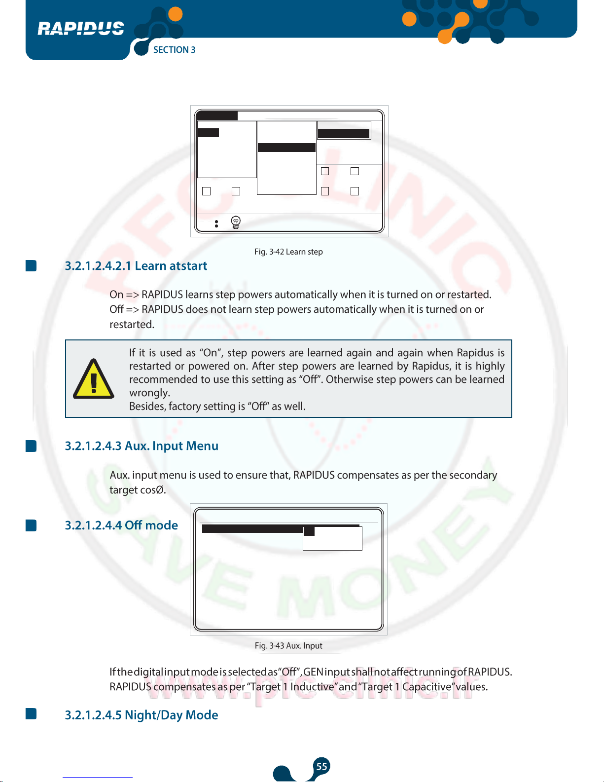
Retry timer
Retry count
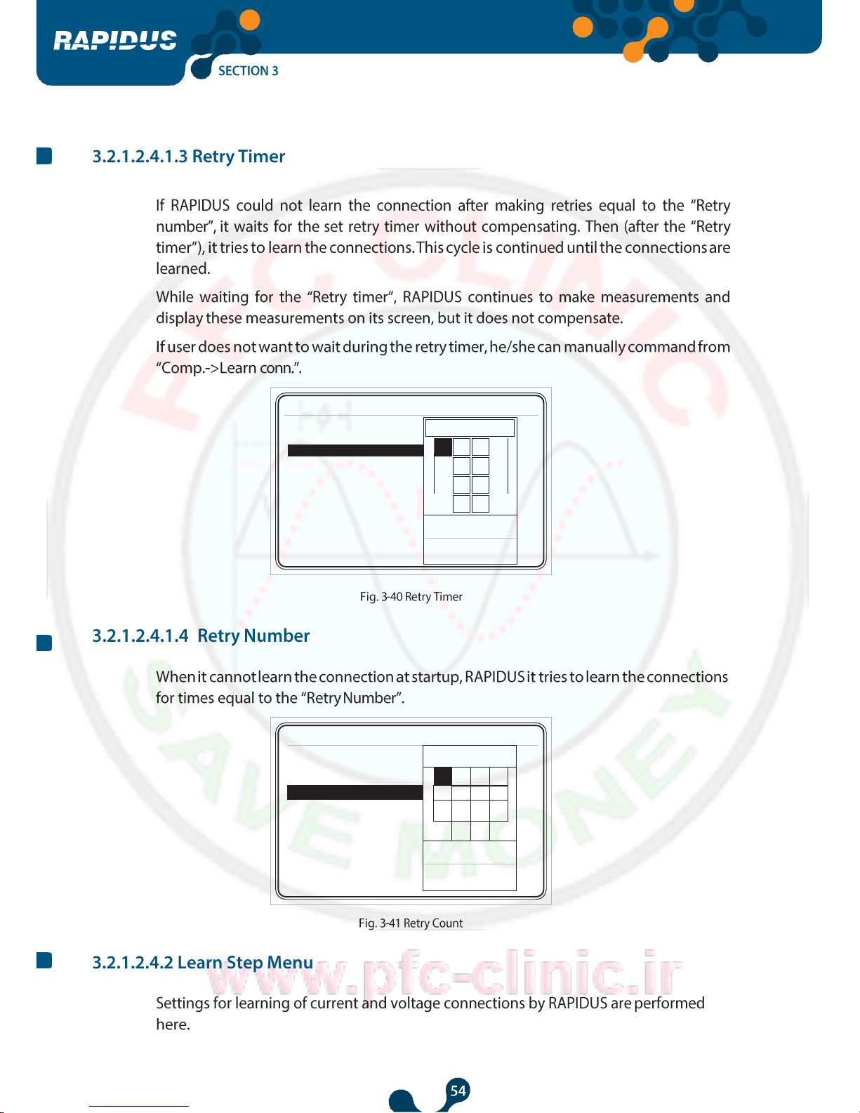
Settings->Setup->Learn->Learn conn.
Off
On

Power Factor Controller
CosØ1 1.000
Qind/P 0
%
CosØ2 1.000
0 5c
CosØ3 1.000
Qcap/P 0
%
Settings Measure Comp.
Alarms
Analysis
RAPIDUS is learning connections.
Please wait...
Retry count : 1
V (L-N)
I
17:27
1 2 3 4 5
6
10.0
10.0
10.0
10.0
10.0
10.0 c c c c c c
7 8 9
10
11
12
10.0
10.0
10.0
10.0
10.0
10.0 c c
c c c
c
17:40
V (L-N)
I
6
10.0
c
12
10.0
c
5
10.0
c
11
10.0
c
4
10.0
c
10
10.0
c
3
10.0
c
9
10.0
c
2
10.0
c
8
10.0
c
1
10.0
c
7
10.0
c
Failed to learn connections! COMPENSATION
WILL NOT BE PERFORMED! Learning will be
retried in 289 secs...
Total retry count : 3
Analysis
Alarms
Measure Comp.
Settings
Power Factor Controller
Settings->Setup->Learn->Learn conn.
1
Low limit
5
High limit
60
Settings->Setup->Learn->Learn conn.
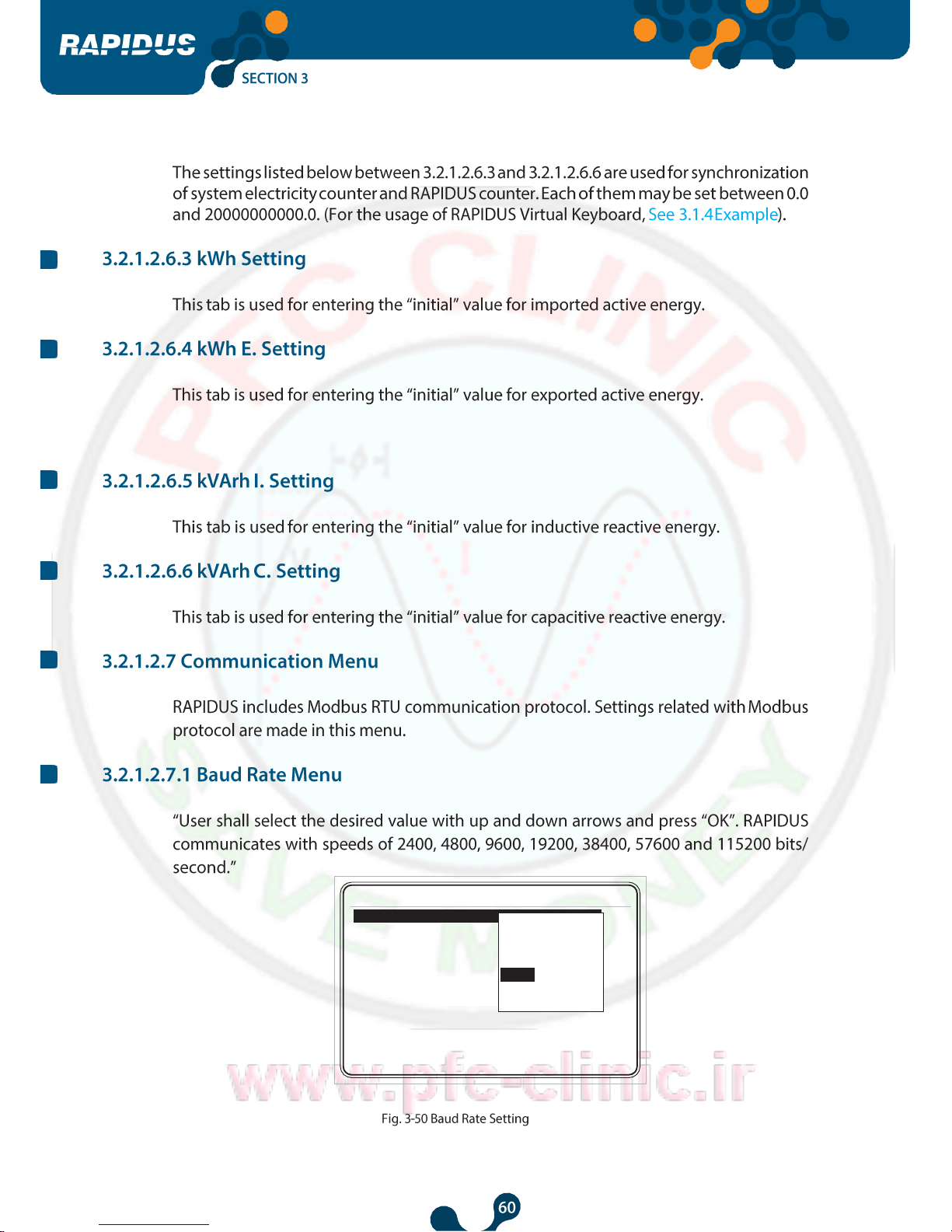
Learn at start
Step number
On
5
Retry timer
5
1 2 3
4
Retry count
3
5 6 7
8
9 0 .
-
ok
clr
Learn at start On
Step number 1
Retry timer 5
3
1 2 3
4
Retry count 3
5 6 7
8
9 0 .
-
ok
clr
Low limit
1
High limit
20
Power Factor Controller
P 1326
Q
4.
S 1326
1 2
10.0 10.0
.4 W
2 VAr
.4 VA
3 4
10.0 10.0
c c
9 10
17:40
V (L-N)
I
6
10.0
c
12
10.0
c
5
10.0
c
11
10.0
c
Clear
10.0 10.0 10.0
c c c
Communication
Alarm
c
8
c
7
10.0
c
Device
Default settings
Energy
Restart
Learn conn.
Learn step
Network
Steps
Compensation
Learn
Aux. input
Quick setup
Setup
Date / Time
System info
Password
Analysis
Alarms
Measure Comp.
Settings
Settings->Setup->Aux. input
Off
Night/Day
Generator

Power Factor Controller
P 1326
Q
4.
S 1326
1 2
10.0 10.0
.4 W
2 VAr
0
.4 VA
3 4
10.0 10.0
c c
9 10
10.0 10.0
14:40
V (L-N)
I
sec.
English
Level -3
Off
1
Time dependent
600
Language
Contrast
Pass. protection
New password
Display on
Display on time
6
10.0
c
12
10.0
c
5
10.0
c
11
10.0
c
c
c
Communication
Alarm
Clear
c
8
10.0
c
c
7
10.0
c
Default settings
Energy
Device
Restart
0
%
50
0
%
Settings->Setup->Device
Network
Steps
Compensation
Learn
Aux. input
Quick setup
Setup
Date / Time
System info
Password
Analysis
Alarms
Measure Comp.
Settings

Power Factor Controller
pendent
sec
Settings->Setup->Device
Language
English
Level -4
Level -3
Level -2
Level -1
Level 0
Level 1
Level 2
Level 3
Level 4
Contrast
Level -3
Pass. protection
Off New password
1
Display on
Time de
Display on time
600 .

Power Factor Controller
pendent
sec.
Settings->Setup->Device
Language
English
1
Contrast
Level -3
1 2 3
4
Pass. protection
On
5 6 7
8
New password
1
Display on
Time de
9 0 .
-
Display on time
600
ok
clr
Low limit
1
High limit
9999
sec.
1
Time dependent
600
New password
Display on
Display on time
Settings->Setup->Device
Language
English
Contrast Level -3
Off
On

Power Factor Controller
pendent
sec.
Ayarlar->Kurulum->Cihaz
Settings->Setup->Energy
Language
English
600
Contrast
Level -3
1 2 3
4
Pass. protection
On
5 6 7
8
New password
1
Display on
Time de
9 0 .
-
Display on time 600
ok
clr
Low limit
10
High limit
600
Start of day
0
Start of month
1
kWh
0.0
kWh
kWh E.
0.0
kWh
kVArh I.
0.0
kVArh
kVArh C.
0.0
kVArh
Power Factor Controller
38400
2400
4800
9600
19200
38400
57600
115200
Slave Id
Settings->Setup->Communication
Baud rate
Power Factor Controller
P 1326
Q
4.
S 1326
1 2
10.0 10.0
.4 W
2 VAr
0
.4 VA
3 4
10.0 10.0
c c
9 10
Slave Id 1
17:40
V (L-N)
I
6
10.0
c
12
10.0
c
5
10.0
c
11
10.0 c 10.0
c
Alarm
Clear
10.0
c
c c
7 8
10.0 10.0
c c
Default settings
Communication
Energy
Restart
0
%
50
0
%
Network
Steps
Compensation
Learn
Aux. input
Quick setup
Setup
Date / Time
System info
Password
Analysis
Alarms
Measure Comp.
Settings

Power Factor Controller
Settings->Setup->Alarm->Energy
Settings->Setup->Alarm->V
Inductive hi limit
20.0 %
Alarm relay
Capacitive hi limit
Alarm relay
Off
15.0
Off
%
Alarm relay
Off
Low limit
0.0 V
High limit
0.0 V
Delay 0
sec.
Hysteresis
0.0 %

Power Factor Controller
Alarm relay Off
Delay 0
sec.
Hysteresis 0.0 %


%
%
Settings->Setup->Alarm->Harmonics V
Alarm relay Off
THDV hi limit 0.0
V3 hi limit 0.0
Off
Relay1
Relay2
V5 hi limit
V7 hi limit
0.0
0.0
%
%
V9 hi limit
0.0 %
V11 hi limit
0.0 %
V13 hi limit
0.0 %
V15 hi limit
0.0 %
V17 hi limit
0.0 %
V19 hi limit
0.0 %
V21 hi limit
0.0 %

V21 hi limit 20.0
%
THDV hi limit 20.0 %
V3 hi limit 20.0
%
Settings->Setup->Alarm->Current
Settings->Setup->Alarm->Current
OK X
Alarm relay
Relay1
Low limit
0.0 A
High limit
0.0 A
Delay
0.0
sec.
Hysteresis
0.0 %
Alarm relay
Relay1
Low limit 0.0 A
High limit 0.0 A
Delay 0.0 sec.
Hysteresis
0.0 %

P 1326
Q 4.
S 1326
1 2
10.0 10.0
.4 W I
2 VAr V
.4 VA
3 4
10.0 10.0
c c
9 10
8.9 A
257.1
V
Measure->Energy->Imp. active
Measure->Energy->Imp. active
Index
267500.1
kWh
0.5
kWh
0.6
kWh
21.3
kWh
22.6
kWh
598.4
kWh
439.5
kWh
Index
0.0
kWh
0.0
kWh
0.0
kWh
0.0
kWh
0.0
kWh
0.0
kWh
0.0
kWh
17:40
V (L-N)
I
6
10.0
c
12
10.0
c
5
10.0
c
11
10.0
c
Clear
10.0 10.0
c c
Communication
Alarm
c
8
10.0
c
c
7
10.0
c
Energy
Demand
Learn
All
1.000
Device
Default settings
Energy
Restart
Network
Steps
Compensation
Learn
Aux. input
Quick setup
Setup
Date / Time
System info
Password
Analysis
Alarms
Measure Comp.
Settings
OK
X
Measure->Energy->Imp. active
Index
7500.0
kWh
Curr. hour
0.0
kWh
Prev. hour
0.0
kWh
Curr. day
0.0
kWh
Prev. day
0.0
kWh
Curr. month
0.0
kWh
Prev. month
0.0
kWh
Settings->Date / Time
Time 18 : 49 : 30
1 2
10.0 10.0
Settings
Measure Comp.
Alarms
Analysis
Quick setup
Setup
Date / Time
System info
Password
Restart
Default settings
Qind/P
0
Qcap/P
0
%
50
0
%
c c
7 8
10.0 10.0
c c
3
10.0
c
9
10.0
c
4
10.0
c
10
10.0
c
5
10.0
c
11
10.0
c
6
10.0
c
12
10.0
c
V (L-N)
I
14:40
Login required!
X
Login success.
OK
Password mismatch.
X
KLEMSAN
RAPIDUS - Power Factor Controller
Model 606000
Serial number 2359339
Language English
Firmware version 1.00
PCB version 1_1-2
Build date 30 August 2014
Temperature 27.1 °C
Battery voltage 3.18 V

1 2
10.0
10.0
1 2
10.0
10.0
17:40
V (L-N)
I
6
10.0
c
12
10.0
c
5
10.0
c
11
10.0
c
4
10.0
c
10
10.0
c
3
10.0
c
9
10.0
c
c c
7 8
10.0 10.0
c c
0
%
50
0
%
Qcap/P
0
Qind/P
Quick setup
Setup
Date / Time
System info
Password
Restart Default
settings
Analysis
Alarms
Measure Comp.
Settings
OK
X
14:40
V (L-N)
I
6
10.0
c
12
10.0
c
5
10.0
c
11
10.0
c
4
10.0
c
10
10.0
c
3
10.0
c
9
10.0
c
c
8
10.0
c
c
7
10.0
c
0
%
50
0
%
Qcap/P
0
Qind/P
Quick setup
Setup
Date / Time
System info
Password
Restart
Default settings
Analysis
Alarms
Measure Comp.
Settings
OK
X

Measure->Instantaneous->V L-N
V
I
150.0
3.000
50.0
V
A
F Hz
THD
V-I-F
CosØ-PF
17:40
V (L-N)
I
6
10.0
c
12
10.0
c
5
10.0
c
11
10.0
c
4
10.0
c
10
10.0
c
3
10.0
c
9
10.0
c
2
10.0
c
8
10.0
c
1
10.0
c
7
10.0
c
0
%
50
0 % Qcap/P
0
Qind/P
Analysis
Alarms
Measure
Comp.
Instantaneous
Energy
Demand
Harmonics

Measure->Energy->Imp. active
Index
Curr. hour
0.0
0.0
kWh
kWh
Prev. hour
0.0
kWh
Curr. day
0.0
kWh
Prev. day
0.0
kWh
Curr. month
0.0
kWh
Prev. month
0.0
kWh


17:42
V (L-N)
I
6
10.0
c
12
10.0
c
5
10.0
c
11
10.0
c
4
10.0
c
10
10.0
c
3
10.0
c
9
10.0
c
2
10.0
c
8
10.0
c
1
10.0
c
7
10.0
c
0
%
50
0
%
Qcap/P
0
Qind/P
Analysis
Alarms
Measure
Comp.
Instantaneous
Energy
Demand
Harmonics
Measure Comp.
Alarms Analysis
Qind/P
-
Measure
>Demand
0
Qcap/P
50
0
%
Act. power
1
10.0
c
7
10.0
c
2
10.0
c
8
10.0
c
3
10.0
c
9
10.0
c
4
10.0
c
10
10.0
c
5
10.0
c
11
10.0
c
6
10.0
c
12
10.0
c
Rea. power
App. power
08:14:59 - 27/05/14
717.0
08:14:59 - 27/05/14
1024.8
08:14:59 - 27/05/14
1252.8
08:14:59 - 27/05/14
W
VAr
VA
V (L-N)
I
17:53
Instantaneous
Energy
Demand
Harmonics
0
%
A
1.7
Current

Measure->Harmonics->V %
Measure->Harmonics->V %
20 %
15 %
10 %
5 % 1 11
21
31
41
51
1 2 3 4 5
1-5
90.55
0.01
30.03
0.00
29.98
6-10
0.00
0.00
0.01
0.01
0.01
11-15
0.02
0.01
0.00
0.02
0.01
16-20
0.02
0.02
0.01
0.00
0.00
21-25
0.01
0.02
0.02
0.01
0.01
26-30
0.01
0.01
0.02
0.01
0.01
31-35
0.01
0.01
0.01
0.00
0.00
36-40
41-45
46-50
0.02
0.01
0.02
0.01
0.00
0.01
0.01
0.01
0.00
0.02
0.01
0.01
0.01
0.01
0.01
I %
V %
I %
I %
V%
I %
17:43
V (L-N)
I
1 2 3 4 5 6
10.0 10.0 10.0 10.0 10.0 10.0
c c c c c c
7 8 9 10 11 12
10.0 10.0 10.0 10.0 10.0 10.0
c c c c c c
0
%
50
0
%
Qcap/P
Learn conn.
Learned conn.
Learn steps
Analysis
Qind/P
0
Alarms
Comp.
Switch count
Conn. time
DCM
Step 12 0
Comp.->Switch count
Step 1 0
Step 2 0
Step 3 0
Step 4 0
Step 5 0
Step 6 0
Step 7 0
Step 8 0
Step 9 0
Step 10 0
Step 11 0

17:57
V (L-N)
I
1 2 3 4 5 6
10.0 10.0 10.0 10.0 10.0 10.0
c c c c c c
7 8 9 10 11 12
10.0 10.0 10.0 10.0 10.0 10.0
c c c c c c
0
%
50
0
%
Qcap/P
0
DCM
Learn conn.
Learned conn.
Learn steps
Analysis
Qind/P
Alarms
Comp.
Switch count
Conn. time
Step 1 0
min
Step 2 0
min
Step 3 0
min
Step 4 0
min
Step 5 0
min
Step 6 0
min
Step 7 0
min
Step 8 0
min
Step 9 0
min
Step 10
0
min
Step 11
0
min
Step 12
0
min
1 2
CosØ1 1.000
Qind/P 0
%
CosØ2 1.000
0 5c
CosØ3 1.000
Qcap/P 0
%
1
Comp..->Learned conn.
L3-N N-L3 L1-N N-L1 L2-N N-L2
k1-l1
l1-k1
k2-l2
l2-k2
k3-l3
l3-k3
Learn success.
240
60 0
180
120
300
60
240
180
10
300
120
120
300
240
60 0
180
300
120
60
240
180 0 0
180
120
300
240
60
180 0
300
120
60
240
17:28
V (L-N)
I
17:58
V (L-N)
I
6
10.0
c
12
10.0
c
5
10.0
c
11
10.0
c
4
10.0
c
10
10.0
c
3
10.0
c
9
10.0
c
2
10.0
c
8
10.0
c
1
10.0
c
7
10.0
c
6
10.0
c
12
10.0
c
5
10.0
c
11
10.0
c
4
10.0
c
10
10.0
c
3
10.0
c
9
10.0
c
Learned conn.
Learn steps
10.0 10.0
c c
7 8
10.0 10.0
c c
Qcap/P
Learning step 1...
0
%
50
0
%
0
Qind/P
Analysis
Measure Comp. Alarms
Settings
Analysis
Alarms
Comp.
Switch count
Conn. time
DCM
Learn conn.

Power Factor Controller
Alarms
Analysis
Qind/P
0
Qcap/P
50
0
%
0
%
Phase
Steps
Other
VAr 1
1 2 3 4 5
6
10.0
10.0
10.0
10.0
10.0
10.0
c c c c c
c
7 8 9
10
11
12
10.0
10.0
10.0
10.0
10.0
10.0
c c c c c
c
V (L-N)
I
17:40
Alarm
Normal
Normal
Normal
Normal
Normal
Normal
Normal
Normal
Normal
Normal
Normal
Alarms->Phase
V
I
P
Q
S
CosØ
PF
V harmonics
THDV
I harmonics
THDI
F
Power Factor Controller
Normal
Normal
Normal
Normal
Normal
Normal
Normal
Normal
Normal
Normal
Normal
Normal
Alarms->Steps
Step 1
Step 2
Step 3
Step 4
Step 5
Step 6
Step 7
Step 8
Step 9
Step 10
Step 11
Step 12
Normal
Normal
Alarm
Alarm
Normal
Normal
Alarms->Other
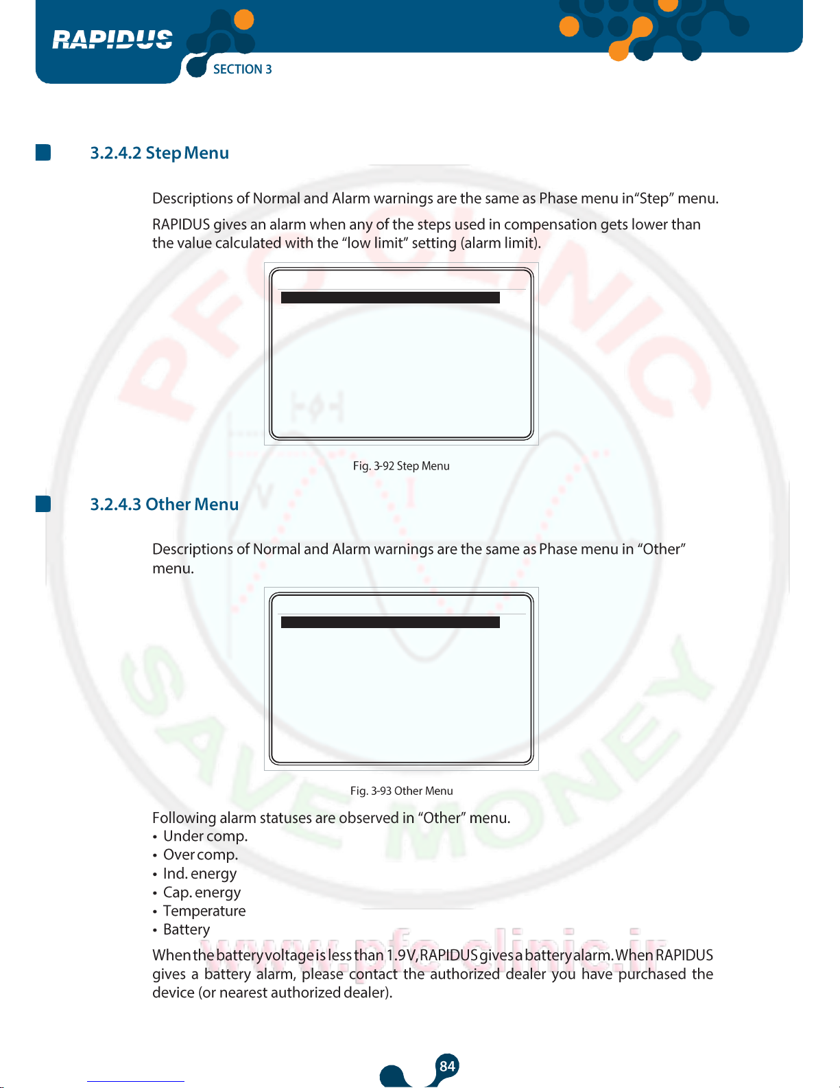
Under comp.
Over comp.
Ind. energy
Cap. energy
Temperature
Battery

Power Factor Controller
1 2
1 2
Qind/P
0
17:59
V (L-N)
I
6
10.0
c
12
10.0
c
5
10.0
c
11
10.0
c
4
10.0
c
10
10.0
c
3
10.0
c
9
10.0
c
10.0
c
8
10.0
c
10.0
c
7
10.0
c
0
%
50
0 % Qcap/P
0
Qind/P
Analysis
Minimum
Maximum
Average
Energy
17:50
V (L-N)
I
6
10.0
c
12
10.0
c
5
10.0
c
11
10.0
c
4
10.0
c
10
10.0
c
3
10.0
c
9
10.0
c
10.0
c
8
10.0
c
10.0
c
7
10.0
c
0
%
50
0
%
Hourly
Daily
Monthly
Qcap/P
Analysis
Minimum
Maximum
Average
Energy

Power Factor Controller
1 2
Qind/P
0
17:51
V (L-N)
I
6
10.0
c
12
10.0
c
5
10.0
c
11
10.0
c
4
10.0
c
10
10.0
c
3
10.0
c
9
10.0
c
10.0
c
8
10.0
c
10.0
c
7
10.0
c
0
%
50
0
%
Hourly
Daily
Monthly
Qcap/P
Analysis
Minimum
Maximum
Average
Energy

Power Factor Controller
Qind/P
0
14:40
V (L-N)
I
6
10.0
c
12
10.0
c
5
10.0
c
11
10.0
c
4
10.0
c
10
10.0
c
3
10.0
c
9
10.0
c
2
10.0
c
8
10.0
c
1
10.0
c
7
10.0
c
0
%
50
0
%
Hourly
Daily
Monthly
Qcap/P
Analysis
Minimum
Maximum
Average
Energy

Power Factor Controller
Power Factor
Controller
Power Factor Controller
Reaktif Güç
Kontrol Rölesi
Reaktif Güç
Kontrol Rölesi
Reaktif Güç Kontrol R ölesi Reaktif Güç Kontrol R ölesi

Power Factor Controller

Power Factor Controller

Power Factor Controller

Power Factor Controller

Power Factor Controller

Power Factor Controller

Power Factor Controller

Power Factor Controller

Power Factor Controller

Power Factor Controller

Power Factor Controller
 Loading...