

1
USER
MANUAL
Energy Analyzer

2
SECTION 1 GENERAL INFORMATION ....................................................... 5
1.1 General Features ................................................................................................... 5
1.2 Poper Use and Safety Conditions ................................................................... 6
1.3 Connection Types .................................................................................................7
1.4 General View&Definitions.................................................................................. 7
1.5 Icons&Leds .............................................................................................................. 8
1.6 Buttons&Their Functions ................................................................................... 8
1.7 Menu Structure ..................................................................................................... 9
1.8 Four Quadrant Representation ......................................................................13
SECTION 2 INSTALLATION .......................................................................14
2.1 Preparation for Installation .............................................................................15
2.2 Mounting ............................................................................................................... 15
2.3 Connection Diagrams ....................................................................................... 15
2.3.1 Connections .........................................................................................................15
2.3.2 Digital Output Connection Diagram .......................................................... .16
2.4 Dimensions (mm) .............................................................................................. 17
SECTION 3 MENUS ....................................................................................18
3.1 Instantaneous Measurements .......................................................................19
3.2 Maximum, Minimum and Demand Values ...............................................19
3.3 Energy Meters (Energy Menu) ......................................................................20
3.4 Prevalue Assignme ............................................................................................21
3.5 Saving Procedure ................................................................................................21
3.6 Counters Menu ....................................................................................................22
3.7 Settings Menu ......................................................................................................23
3.8 Value Changing ...................................................................................................28
3.9 Main Settings (Basic) .........................................................................................28
3.10 Alarm Settings (Alarms)....................................................................................28
3.11 Demand Time Setting (Demand) .................................................................29
3.12 RS485 Setting (RS485) .......................................................................................29
3.13 Digital Output Settings (Dig Out) ................................................................. 30
3.14 Pulse Output Settings (Pulse) .........................................................................30
3.15 Password Settings (Security) ..........................................................................31
3.16 Display Settings (Display) ................................................................................ 31
3.17 Clear Menu (Clear) .............................................................................................. 32
3.18 Confirmation Procedure ..................................................................................33
SECTION 4 RS485 COMMUNICATION ....................................................34
4.1 Applying Multiple Option Settings With Modbus ..................................40
4.2 Status Flags ...........................................................................................................41
SECTION 5 FACTORY PREVALUES AND SETTİNG RANGES ................42
SECTION 6 TECHNICAL SPECIFICATIONS ..............................................47
TABLE OF CONTENTS

3
FIGURES
Fig. 1-1 Connections ........................................................................................................... 7
Fig. 1-2 General view of the device ................................................................................ 7
Fig. 1-3 LCD icon descriptions ......................................................................................... 8
Fig. 1-4 Segment display LED descriptions ................................................................. 8
Fig. 1-5 Four Quadrant Representation ......................................................................13
Fig. 2-1 Connection Diagram ......................................................................................... 16
Fig. 2-2 Digital Output Connection Diagram ( POWYS 10xx ) ............................16
Fig. 2-3 Dimensions ........................................................................................................... 17
Fig. 3-1 Example of instantaneous measurement page (Reactive power) ....19
Fig. 3-2 Example of demand page (Active power) .................................................20
Fig. 3-3 Example of Import Active Energy Meter Display .................................... 21
Fig. 3-4 Save Prosedure ....................................................................................................22
Fig. 3-5 Counters Menu ....................................................................................................23
Fig. 3-6 Alarm Example(Alarm delay is set to be zero) ..........................................29
Fig. 3-7 Confirmation Prosedure ...................................................................................33
TABLES
Table 1-1 Button functions ................................................................................................... 9
Table 1-2 Instantaneous measurements and submenus (LCD devices) ...........10
Table 1-3 Instantaneous measurements and submenus (7-Segment devices) ....11
Table 1-4 Energy, counter, harmonics and settings menus ....................................12
Table 3-1 SETTINGS Menu tree .........................................................................................28
Table 4-1 MODBUS table .................................................................................................... 40
Table 5-1 Factory Prevalu ....................................................................................................46
Table 6-1 Measurement Accuracy....................................................................................49

4
SECTION 1
GENERAL
INFORMATION
Enerji Analizörü
5
SECTION 1 GENERAL INFORMATION
1.1 General Features
POWYS 1xxx series is an energy analyzer designed for single phase systems, measuring
the following parametres:
• Voltage
• Current
• Network frequency
• CosØ value
• Power factor
• Active power
• Reactive power
• Apparent power
• THDV
• THDI
• Voltage and current harmonics between 1-31
In addition to the measurement features, it also executes the following functions:
• Import active, export active, import reactive, export reactive energy meters
• Demand values for current, active power, reactive power and apparent power are
calculated and stored in its memory.
• Establishes and stores in its memory the maximum and minimum values reached
by current, voltage, frequency, cosØ, power factor, THDV, THDI, active, reactive and
apparent powers
• Assigns alarms for current, voltage, frequency, cosØ and power factor parameters
• Keeps the on hour, run hour and number of power interruption
• CTR setting that may be entered from 1 to 5000
• VTR setting that may be entered from 0.1 to 5000
• RS485 communication that may be adjusted from 1200 to 57600 baud (POWYS 11xx)
• Communication with MODBUS RTU (POWYS 11xx)
• 2 pulse outputs can be used for high and low alarm outputs(POWYS 10xx)
• Pulse outputs that may be assigned to the energy values as output parametre (POWYS
10xx)
• Unauthorized access protection with 4 digit user password
• Adjustable automatic menu browsing feature
SECTION 1 GENERAL INFORMATION
6
• Adjustable LCD backlight on duration
• Sealable cover
• Low power consumption
• A wide range of feeding and operating temperature
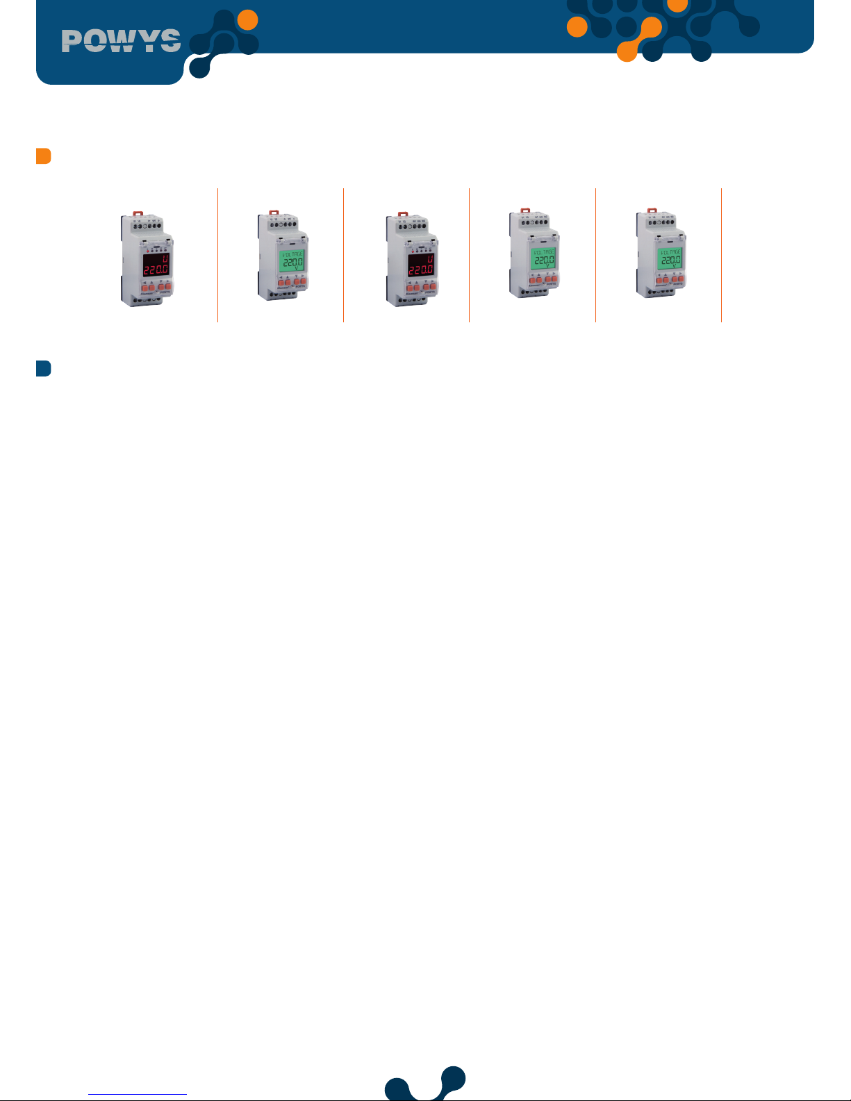
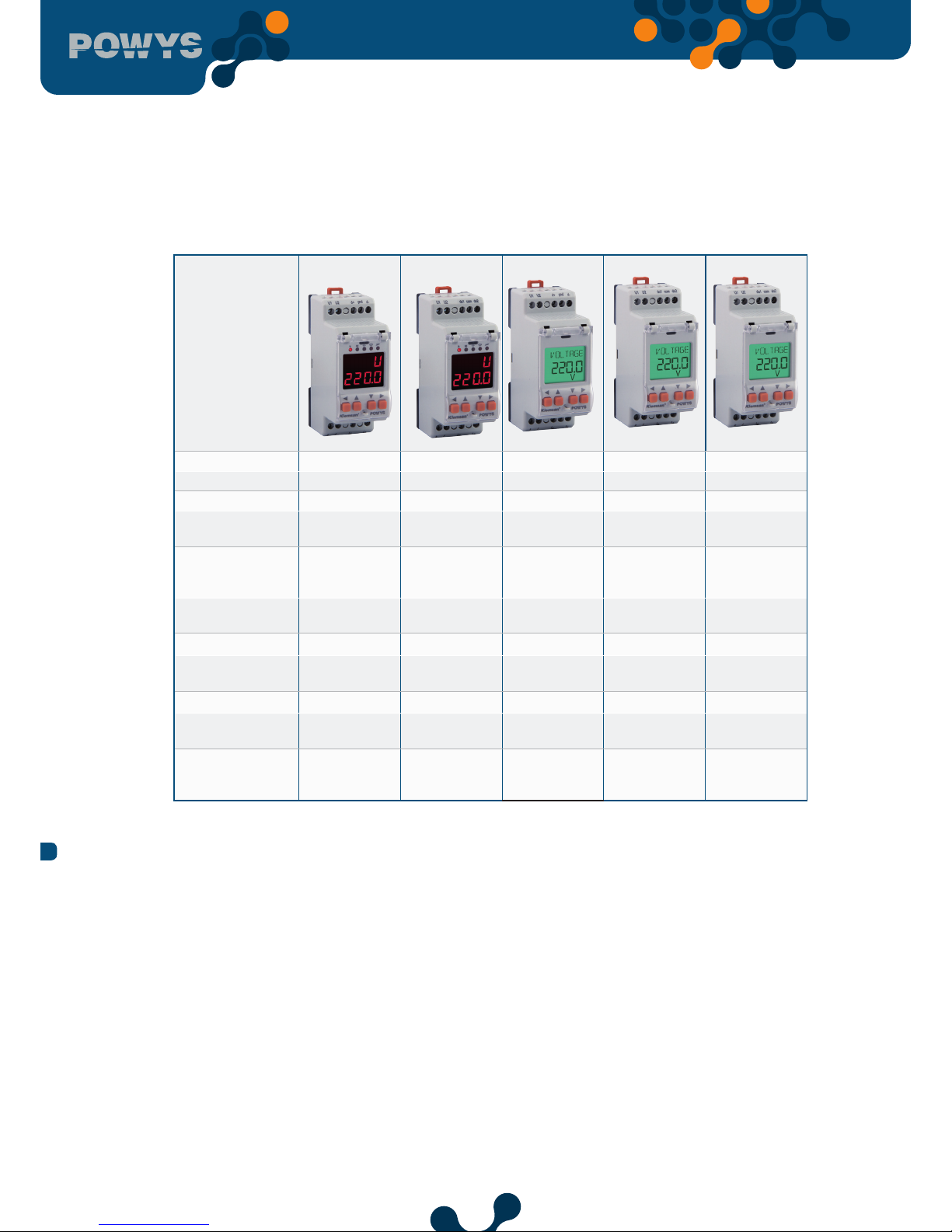
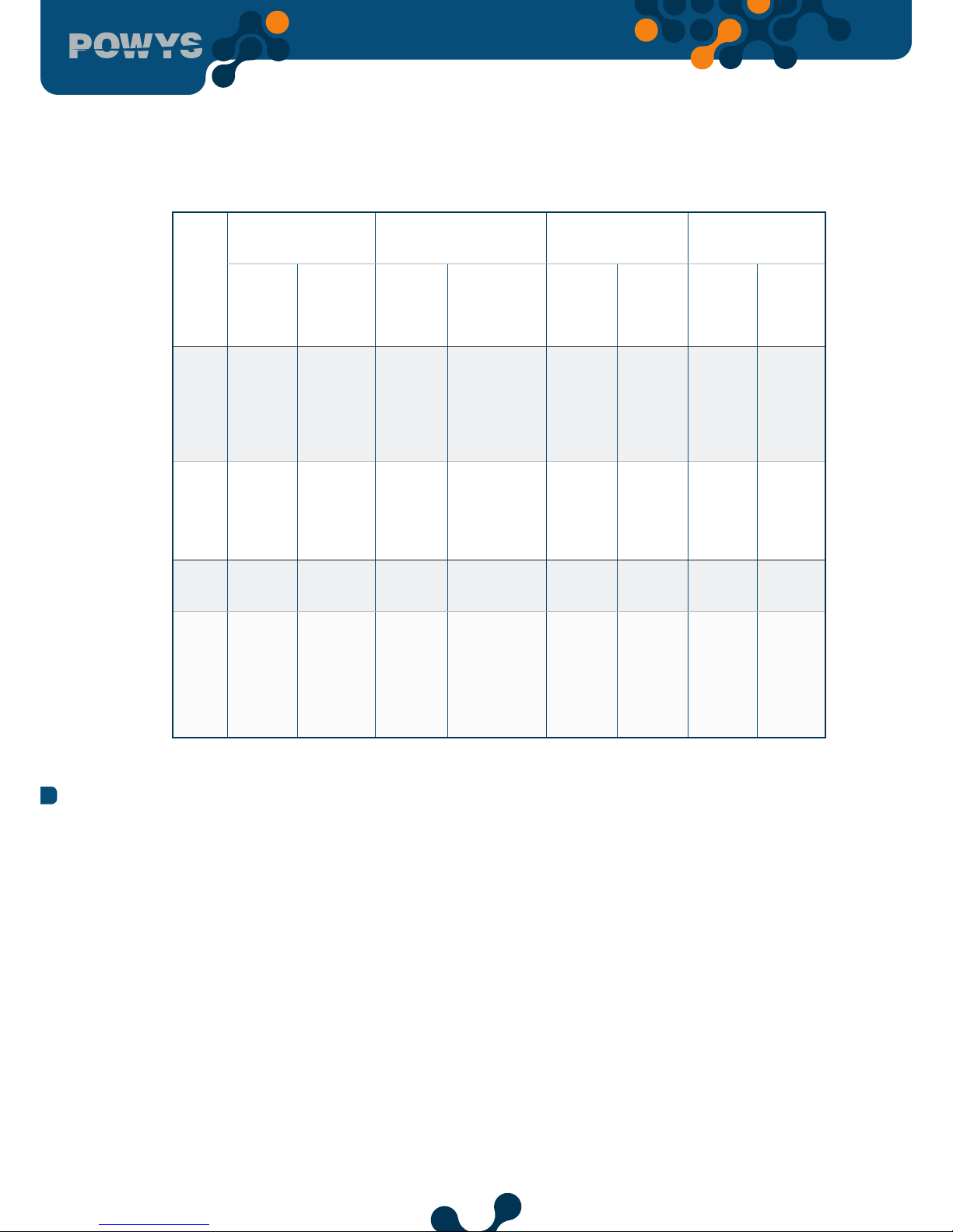
Device model POWYS 1110 POWYS 1012 POWYS 1120 POWYS 1022 POWYS 1023
Order number 606 351 606 354 606 352 606 355 606 356
Connection Rail mount Rail mount Rail mount Rail mount Rail mount
Basic
measurements
● ● ● ● ●
Minimummaximum value
storage
● ● ● ● ●
Demand
measurements
● ● ● ● ●
LCD - -
● ● ●
7-segment displays
and leds
● ● ●
- -
Alarm definition
● ● ● ● ●
RS485
communication
●
-
●
- -
Digital output that
may be assigned to
pulse or alarms
- 2 pcs
●
2 pcs 2 pcs
1.2 Poper Use and Safety Conditions
• Installation and connections should be established in accordance with the instructions
set out in the manual by authorized persons. Unless the connection is built properly,
device should not be operated.
• Before wiring the device up, make sure that energy is cut o
• Do not disconnect the POWYS current transformer connection before short circuiting
the k-1 tips of the current transformer somewhere else. Otherwise, dangerous high
voltages may emerge at the secondary tips of the current transformer.
• Use a dry cloth to remove the dust from the device/clean the device. Avoid using
alcohol, thinner or a corrosive material.
• Device should be engaged only after all the connections are made.
• Do not open the inside of the device. There are no parts which the users can intervene
inside.
SECTION 1 GENERAL INFORMATION
7
• Device should be kept away from humid, wet, vibrant and dusty environments.
• It is recommended to connect a breaker or automatic fuse (2 amper) between the
voltage inputs of the device and the network.
The manufacturing company may not be kept responsible for unfavorable
incidents that arise out of the failure to follow the above cautions.
1.3 Connection Types
POWYS 1110
POWYS 1120
POWYS 1012
POWYS 1022
POWYS 1023
Fig. 1-1 Connections
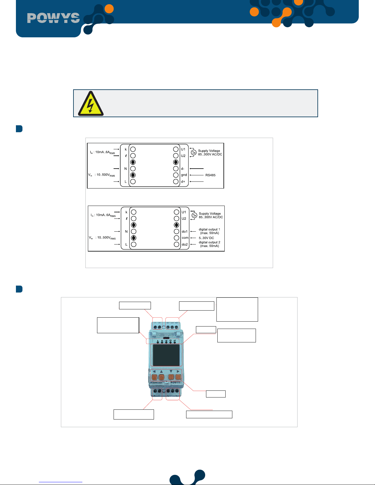
1.4 General View&Definitions
Supply terminal
Output terminals
RS485 terminals or
Digital output terminals
Display
LCD or 7-Segment
Display group
Status LEDs
(Vaild for 7-Segment
models
Buons
Current input terminals
Voltage input terminals
Fig. 1-2 General view of the device
SECTION 1 GENERAL INFORMATION
8
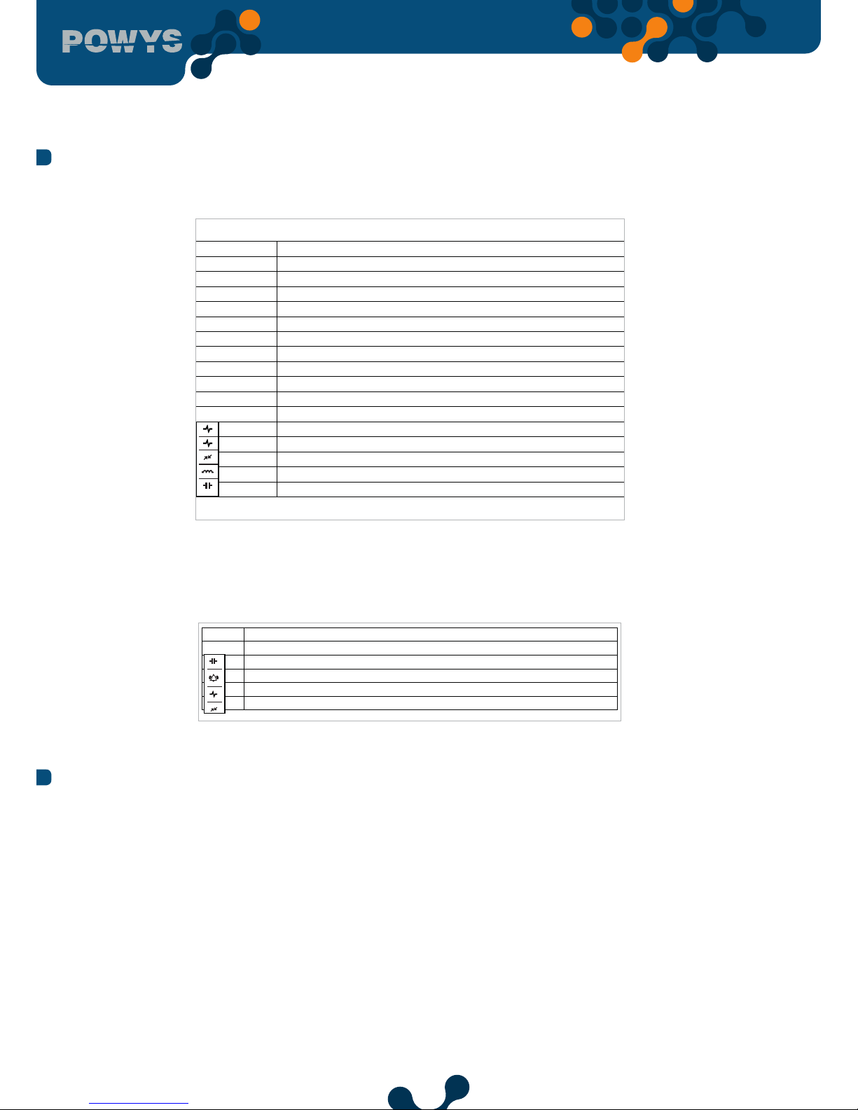
1.5 Icons&Leds
The descriptions of the icons appearing on the display of the devices with LCD are
provided as follows:
Imp
activated when the import meters are shown
Exp
activated when the reactive meters are shown
act
activated when the active meters are shown
rea
activated when the reactive meters are shown
run
activated when the total run hour is shown
on
activated when the total on hour is shown
int
activated when the total number of power interruptions is shown
max
activated when the maximum values are shown
min
activated when the minimum values are shown
demand
activated when the demand values are shown
kVArh
unit of the reactive meters
kWh
unit of the active meters
activated when giving pulse from the 1st pulse output
activated when giving pulse from the 2nd pulse output
activated during RS485 communication
activated if the value shown is inductive
activated if the value shown is capacitive
1
2
Fig. 1-3 LCD icon descriptions
For 7-segment display devices, the ash status of LEDs located in the upper part of the
display is described as below:
k
shows that value written on the display is divided into 1000
M
shows that value written on the display is divided into 1000000
if the value shown is capacitive, it gets activated
shows that at least 1 alarm is present
activated when giving a pulse from any one of the pulse outputs
activated during RS485 communication
Fig. 1-4 Segment display LED descriptions
1.6 Buttons&Their Functions
The buttons valid on the front panel and their functions are described on the following
table:
SECTION 1 GENERAL INFORMATION
9
In the MEASUREMENTS
menus
In the ENERGY, COUNTER,
HARMONICS, SETTINGS
menus
ASSIGNING PRE
VALUES TO THE
METERS
CHANGE SETTINGS
SHORT
PRESSING
( t < 2sec )
LONG
PRESSING
( t > 2sec )
SHORT
PRESSING
( t < 2sec )
LONG PRESSING
( t > 2sec )
SHORT
PRESSING
( t < 2sec )
LONG
PRESSING
( t > 2sec )
SHORT
PRESSING
( t < 2sec )
LONG
PRESSING
( t > 2sec )
RIGHT
Switches
between
menus
Skips
to the
"ENERGY"
menu
Switches
to the
submenu
Skips to the
menu at the
bottom
Changes
the active
digit
Activates
changing
value
Activates
changing
value or
changes
the
active
step
No eect
DOWN
Switches
between
menus
No eect
Switches
between
menus
No eect
Changes
value
No eect
Changes
value
No eect
UP
Switches
between
menus
No eect
Switches
between
menus
No eect
Changes
value
No eect
Changes
value
No eect
LEFT
Switches
between
menus
Skips
to the
homepage
Switches
between
menus
Skips to the
most recent
menu in the
measurements
menu
Stops
changing
value and
confirms
the value
entered
No eect
Stops
changing
value
and
confirms
the value
entered
No eect
Table 1-1 Button functions
1.7 Menu Structure
Instantaneous measurement menus and the menus showing their related maximum,
minimum and demand values are provided in the following table. As provided in the
table, down, up, right and left handside buttons provide menu switches.
SECTION 1 GENERAL INFORMATION

10
menu max min demand
↕
↕
↕
↔ VOLTAGE ↔ max ↔ min ↔
↔
↕
↕
↕
↕
↔ CURRENT ↔ max ↔ min ↔ demand ↔
↕
↕
↕
↕
↔ FREQ ↔ max ↔ min ↔
↕
↕
↕
↔ COSQ ↔ max ↔ min ↔
↕
↕
↕
↔ PF ↔ max ↔ min ↔
↔
↕
↕
↕
↕
↔ POWER P ↔ max ↔ min ↔ demand ↔
↕
↕
↕
↕
↔ POWER Q ↔ max ↔ min ↔ demand ↔
↕
↕
↕
↕
↔ POWER S ↔ max ↔ min ↔ demand ↔
↕
↕
↕
↕
↔ THD V ↔ max ↔ min ↔
↕
↕
↕
↔ THD I ↔ max ↔ min ↔
↕
↕
↕
Table 1-2 Instantaneous measurements and submenus (LCD devices)
SECTION 1 GENERAL INFORMATION

11
menu max min demand
↕
↕
↕
↔ Uolt ↔ H - U ↔ L - U ↔
↔
↕
↕
↕
↕
↔ Curr ↔ H - I ↔ L - I ↔ d - I ↔
↕
↕
↕
↕
↔ FrEq ↔ H - F ↔ L - F ↔
↕
↕
↕
↔ coSQ ↔ H - co. ↔ L - co. ↔
↕
↕
↕
↔ PF ↔ H - PF ↔ L - PF ↔
↔
↕
↕
↕
↕
↔ Act ↔ H - Ac. ↔ L - Ac. ↔ d - Ac. ↔
↕
↕
↕
↕
↔ rEA ↔ H - rE. ↔ L - rE. ↔ d - rE. ↔
↕
↕
↕
↕
↔ APr ↔ H - AP ↔ L - AP ↔ d - AP ↔
↕
↕
↕
↕
↔ tHdU ↔ H - t.U ↔ L - t.U ↔
↕
↕
↕
↔ tHdI ↔ H - t.I ↔ L - t.I ↔
↕
↕
↕
Table 1-3 Instantaneous measurements and submenus (7-Segment devices)
Energy meters, counters, odd harmonics between 1-31 and menus showing the settings
are provided in the following table. As provided in the table, down, up, right and left
handside buttons provide menu switches.
SECTION 1 GENERAL INFORMATION
12
ENERGY
↔ IMPORT ACTIVE
↕
← EXPORT ACTIVE
↕
← IMPORT REACTIVE
↕
← EXPORT REACTIVE
↕
COUNTERS
↔ RUN HOUR
↕
← ON HOUR
↕
← POWER INT. COUNTER
↕
HARMONICS
↔ V HARM
↔ V HARM 1
↕
← V HARM 3
← .
← .
← V HARM 31
↕
← I HARM
↔ I HARM 1
↕
← I HARM 3
← .
← .
← I HARM 31
↕
SETTINGS ↔ (SETTINGS MENU TREE)
Table 1-4 Energy, counter, harmonics and settings menus
SECTION 1 GENERAL INFORMATION
13
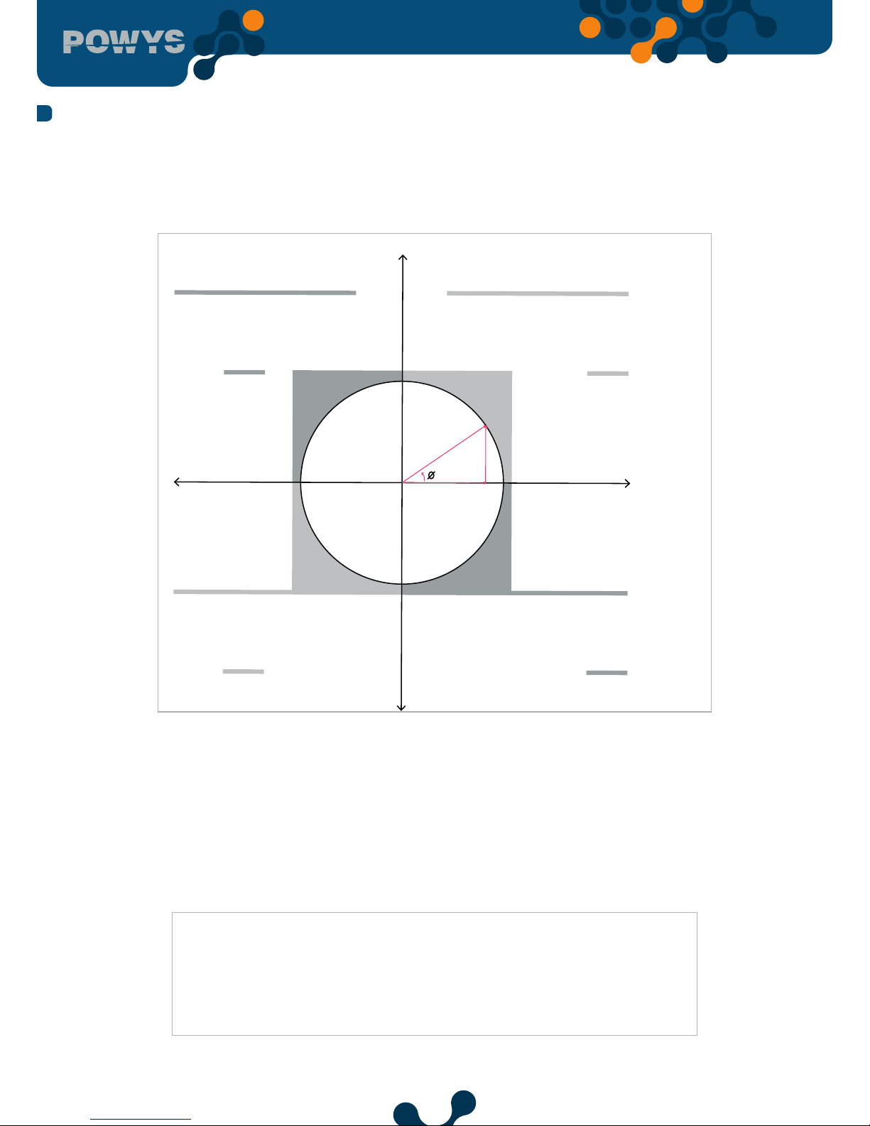
1.8 Four Quadrant Representation
The angle(Ø) between voltage and current provides us information about the direction of energy
ow. A positive sign for active/reactive power indicates that active/reactive power is consumed. And
also a negative sign for active/reactive power indicates that active/reactive power is generated.
Meters
Imp. Active &
Imp. Reactive
Active Power
Reactive Power
Meters
Exp. Active &
Imp. Reactive
QUADRANT -1
P => positive
Q => positive & inductive
CosØ => inductive
PF => positive
QUADRANT -2
P => negative
Q => positive & capacitive
CosØ => capacitive
PF => negative
Meters
Imp. Active &
Exp. Reactive
Meters
Exp. Active &
Exp. Reactive
QUADRANT -4
P => positive
Q => negative & capacitive
CosØ => capacitive
PF => positive
QUADRANT -3
P => negative
Q => negative & inductive
CosØ => inductive
PF => negative
S
P
Q
Fig. 1-5 Four Quadrant Representation
NOTE: If the signs of active and reactive power are examined, it can be defined the quadrant that
POWYS measures.
In order to understand P and Q signs in POWYS 10xx and POWYS 11xx, instantaneous displays for P
and Q must be checked.
If active power display is seem constantly, it means active power(P) is positive. If it is blinked, it
means active power(P) is negative.
If reactive power(Q) display is seem constantly, it means reactive power(Q) is positive. If it is
blinked, it means reactive power(Q) is negative.
NOTE: Signs of P and Q can be reached through modbus communication.
e.g.; P= +10kW, Q= +5kVAr => Quadrant-1
P= -10kW, Q= +5kVAr => Quadrant
-2
P= -10kW, Q= -5kVAr => Quadrant
-3
P= +10kW, Q= -5kVAr => Quadrant
-4
SECTION 1 GENERAL INFORMATION

14
SECTION 2
INSTALLATION
Energy Analyzer
15
SECTION 2 INSTALLATION
SECTION 2 INSTALLATION
2.1 Preparing for Installation
The purchased product may not include all hardware options referred in this document. This
situation does not constitute an impediment to the electrical installation.
Assembly and related connections of the product, must be implemented by
authorized persons in accordance with the instructions of user manual.
The device must not be put into service if the operator is not sure that all connections
are correctly accomplished.
2.2 Mounting
POWYS 10xx and POWYS 11xx are replaced onto 35mm standart rail.
Before wiring up voltage and current ends to POWYS, you must be sure that the
power is cut.
The product is connected to current transformer(s). Before disconnecting current
transformer leads, be sure that they are short circuited elsewhere or connected to
a parallel load which has suiciently low impedance. Otherwise dangerously high
voltages will be induced at the current transformer leads. Same phenomena also
apply for putting into service.
2.3 Connection Diagrams
2.3.1 Connections
POWYS 10xx and POWYS 11xx are replaced onto 35mm standart rail.

16
SECTION 2 INSTALLATION
Current Voltage
Fig. 2-1 Connection Diagram
2.3.2 Digital Output Connection Diagram
External DC Power Supply must be
connected.
(5-30VDC)
yük
DO (-)DO (+)
+
-
Fig. 2-2 Digital Output Connection Diagram ( POWYS 10xx )

17
SECTION 2 INSTALLATION
2.4 Dimensions (mm)
Fig. 2-3 Dimensions

18
SECTION 3
MENUS
Energy Analyzer

19
SECTION 3 MENUS
3.1 Instantaneous Measurements
Instantaneous measurement menus and the menus showing their related maximum,
minimum and demand values are provided in the following table. As provided in the
table, down, up, right and left handside buttons provide menu switches.
Example of Reactive
power display for LCD
devices
Example of Reactive
power display for
7-segment devices
Fig. 3-1 Example of instantaneous measurement page (Reactive power)
“- - - -“ icon which appears in the menus showing instantaneous measurement refers
to the value being higher than 99 999 999 For Powys 1023, shown in 9 999 999.9 kWh
/ kVArh format.
3.2 Maximum, Minimum and Demand Values
Minimum and maximum values of the voltage, current, frequency, CosØ, power factor,
active power, reactive power, apparent power, THDV and THDI parametres as well as
the demand values of current, active, reactive and apparent power are calculated by
the device and stored in the permanent memory. Right or left handside buttons in the
measurement menus display the maximum, minimum measurements and demand
values. Menu switches are shown in the Table 2.
The values stored in the memory may be selected from the “CLEAR” menu located in the
“SETTINGS” menu to be erased. Furthermore, resetting is also possible via resetting or
restoring the factory settings commands for devices with RS-485 communication
SECTION 3 MENUS

20
Example of Reactive
power display for LCD
devices
Example of Reactive
power display for
7-segment devices
Fig. 3-2 Example of demand page (Active power)
“- - - -” icon appearing in the menus which shows minimum values refer to the fact
that no value has yet to be saved as a minimum value.
3.3 Energy Meters (Energy Menu)
Under the “ENERGY” menu, import active, export active, import reactive and export
reactive meters are valid.
Menu structure is as follows:
SECTION 3 MENUS

21
LCD display devices 7-segment display devices
ENERGY
↔ IMPORT ACTIVE
"imp" and "act" icons flash on the screen
Menu tle: I.Act.
↕
← EXPORT ACTIVE
"exp" and "act" icons flash on the screen Menu tle: E.Act.
↕
← IMPORT REACTIVE
"imp" and "rea" icons flash on the screen
Menu tle: I.rEA.
↕
← EXPORT REACTIVE
"exp"
and
"rea"
icons flash on the screen Menu tle:
E.rEA.
Meters are shown in the following format:
xx xxx xxx kWh / kVArh. For Powys 1023, shown
in x xxx xxx.x kWh / kVArh format. During the
meter screening, values for the most recent
measurement menu are continously updated in
the indicators at the bottom (LCD display
devices)
All the meters continue to count after being
resetted subsequent to the 99 999 999 kWh /
kVArh value. For Powys1023, all the meters
continue to count after being resetted
subsequent to the 9 999 999.9 kWh /kVArh
value.
Fig. 3-3 Example of Import Active Energy Meter Display
3.4 Prevalue Assignment
While in a menu to which a value can be assigned, press the right button 2 seconds, the
first digit of the related meter will start to blink. Go to the digit you want changed with
the right arrow button and enter a value with up/down arrows. When the value entering
is completed, confirm the value with the left arrow button. Go to the saving procedure
in order to save the changes made. See: Saving procedure.
3.5 Saving Procedure
In order to save or cancel the changes, keep pressing the left button until the “SAVE”
screen shows.
SECTION 3 MENUS

22
If the changes are to be saved:
I
f the changes are to be cancelled:
Press the right button so that
“NO” sign starts blinking.
Pressing the down/up buttons,
“NO” sign turns into “YES” sign.
Then, pressing the left button,
save the changes.
Press the right button so that
“NO” sign starts blinking. Then,
press the left button to exit the
menu without saving the
changes made.
Fig. 3-4 Save Prosedure
3.6 Counters Menu
The following counters are valid under the “COUNTERS” menu.
• “ON HOUR” : The total on hour of the device is counted and shown in the “ON HOUR”
counter in hours.
• “RUN HOUR” : If current and voltage signals are applied to the related inputs of the
device altogether, the time lapsed is counted and shown in hours.
• “POWER INTERRUPTION COUNTER” : Shows the number of power interruptions of the
device.
• Menu structure is provided below
SECTION 3 MENUS

23
LCD display devices 7-segment display devices
COUNTERS
↔ RUN HOUR
"run" icon flashes on the screen
Menu tle : run
↕
← ON HOUR
"on" icons flashes on the screen Menu tle: on
↕
←
POWER INT.
COUNTER
"int" icons flashes on the screen Menu tle: Int
Fig. 3-5 Counters Menu
The counters are shown in 8 digits. All of the counters are resetted after the value
99 999 999 and then continue to count.
Value assignment and resetting only apply to the “RUN HOUR” meter. In order
to assign any value to the meter, prevalue assigning procedure is applied. See:
Prevalue Assignment
During counter screening, values for the most recent measurement value keep
updating in the indicators valid at the bottom. (for LCD devices)
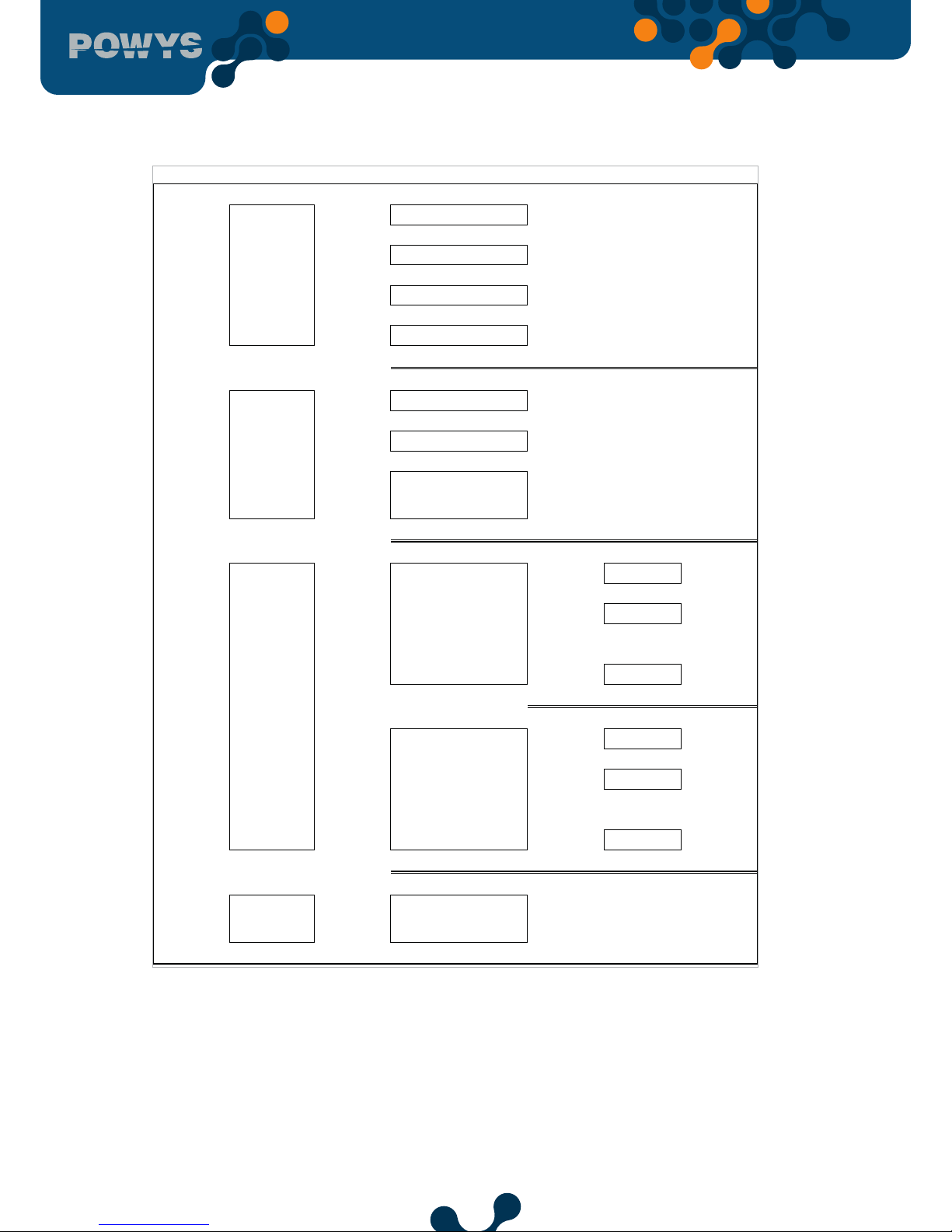
3.7 Settings Menu
The menu tree table for the “SETTINGS” menu which enables device setting is provided
below. The screening for 7-segment devices are provided in parantheses.
SECTION 3 MENUS

24
Menu Submenu 1 Submenu 2
Submenu
3
Submenu 4
Description
SETTING S
Settings
BASIC
(bSc)
Basic settings
Ctr Current transformer ratio
Utr Voltage transformer ratio
ALARMS
(ALr)
V ALM
(Uolt)
Alarm settings
HI Voltage alarm settings
LO Voltage alarm upper limit
hYSt Voltage alarm lower limit
dlY.t Voltage alarm hysteresis value
I ALM
(Curr)
Current alarm settings
HI Current alarm upper limit
LO
Current alarm lower limit
hYSt
Current alarm hysteresis value
dlY.t
Current alarm delay time
SECTION 3 MENUS

25
SETTING S
ALARMS
(ALr)
V ALM
(Uolt)
Voltage alarm settings
HI
Voltage alarm upper limit
LO
Voltage alarm lower limit
hYSt
Voltage alarm hysteresis value
dlY.t
Voltage alarm delay time
I ALM
(Curr)
Current alarm settings
HI Current alarm upper limit
LO Current alarm lower limit
hYSt Current alarm hysteresis value
dlY.t Current alarm delay time
COSQ ALM
(coSQ)
cos φ alarm settings
HI
cos φ alarm upper limit
LO
cos φ alarm lower limit
hYSt
cos φ alarm hysteresis value
dlY.t
cos φ alarm delay time
PF ALM
(PF)
Power factor alarm settings
HI Power factor alarm upper limit
LO Power factor alarm lower limit
hYSt
Power factor alarm hysteresis
value
dlY.t Power factor alarm delay time
FREQ ALM
(FrEq)
Frequency alarm settings
HI Frequency alarm upper limit
LO Frequency alarm lower limit
hYSt
Frequency alarm hysteresis
value
dlY.t Frequency alarm delay time
DEMAND
(dEd)
Demand value
dEd.t Demand time setting
RS485
(485)
RS485 setting (ATTENTION!
: This menu is only valid for
devices with RS485 output)
bAud
Baud rate options
Id
Slave ID setting
PrtY
Parity control setting
NONE Parity control o
EVEN Even parity
ODD Odd parity
SECTION 3 MENUS

26
DIG OUT
(dOut)
Digital output options (ATTENTION! : This
menu is only valid for devices with digital
output)
OUT1
(Out1)
1st digital output settings
tYPE
1st digital output type settings
OFF O
PULSE (PuLS) Assign as pulse output
LOW ALM (ALr.L) Assign as low alarm output
HIGH ALM (ALr.H) Assign as high alarm output
OUT2
(Out2)
2nd digital output settings
tYPE
2nd digital output type settings
OFF O
PULSE (PuLS) Assign as pulse output
LOW ALM (ALr.L) Assign as low alarm output
HIGH ALM (ALr.H) Assign as high alarm output
PULSE
(PuLS)
Pulse output settings (ATTENTION! : This
menu is only valid for devices with digital
output)
OUT1
(Out1)
1st pulse output setting
out
1st pulse output parameter setting
OFF O
IMP ACT (I.Act.) Assign to the import active energy meter
EXP ACT (E.Act.) Assign to the export active energy meter
IMP REA (I.rEA.) Assign to the import reactive energy meter
OUT2
(Out2)
EXP REA (E.rEA.) Assign to the export reactive energy meter
durA Pulse duration of the 1st pulse output
rAt 1st pulse output step range
2.pulse output setting
out
2nd oulse output parameter setting
OFF o
IMP ACT (I.Act.) Assign to the import active energy meter
EXP ACT (E.Act.) Assign to the export active energy meter
IMP REA (I.rEA.) Assign to the import reactive energy meter
EXP REA (E.rEA.) Assign to the export reactive energy meter
durA
Pulse duration of the 2nd pulse output
rAt
2nd pulse output step range
SECURITY
(PIn)
Password protection setting
Act
Activate/deactivate the password protection
NO
Password protection passive
YES
Password protection active
SECTION 3 MENUS

27
Pin.t
Password protection timeout duration. After
entering the password, if no other button
is pressed or no setting is changed with
MODBUS, password protection is activated at
the end of the period.
Pin
Password value
Display setting
MENU
Menu settings
ScrL
Menu browsing setting
OFF Menu browsing o
ON Menu browsing on
Scr.P
Menu screening duration
Strt
Homepage setting
VOLTAGE (Uolt) Homepage Voltage
CURRENT (Curr) Homepage Current
FREQ (FrEq) Homepage Frequency
COSQ (coSQ) Homepage CosQ
PF (PF) Homepage Power factor
POWER P (Act)
Homepage active p
ower
POWER Q (rEA) Homepage reactive power
POWER S (APr) Homepage apparent power
THD V (tHdU) Homepage THD Voltage
THD I (tHdI) Homepage THD Current
BACKLGHT
Display backlight setting (ATTENTION! : This
menu is only valid for devices with LCD)
oPt
Display backlight options
DURATION DEP Display backlight is on depending on time
CONT ON Display backlight is continuously on
CONT OFF Display backlight is contiously o
durA Display backlight on duration
CLEAR
(CLr)
Clear menu
CLr
OFF Clearing cancelled
ALL Restore the factory settings for the device
ENERGY (Enr)
Clear the energy meters
COUNTERS
(Cnt)
Clear the counter
MAX VALS (HI)
Clear the maximum values
MIN VALS (LO)
Clear the minimum values
DEMANDS
(dEd)
Clear the demand values
SETTINGS (SEt) Restore the settings to the factory settings
ALARMS (ALr)
Restore the alarm settings to the factory
settings
SECTION 3 MENUS

28
INFO
(InFo)
Informing
UEr Firmware version information
Table 3-1 SETTINGS Menu tree
3.8 Value Changing
There are 2 dierent value changing menus:
• Multiple choice menus: Theese menus enable predefined options. In these menus, press the
right button so that the first option of the menu starts to blink. Press the up/down buttons
so that the option starts blinking in the screen. Then, press the left button to complete the
selection.
• Menus where digital values are entered: Browsing among the steps, this menu enables to set
the value of your choice. Press the right button so that the first step from the left of the variable
starts blinking. Right button enables to switch among the steps. Press the up/down buttons to
change the value on the active step. When the values on the step are set and the variable is set
to the number of your choice, press the left button to complete the selection.
If a change is made in the settings, when you return to the “SETTINGS” menu,
saving procedure is enabled asking whether or not to save the changes. See: Saving
Procedure. If the changes are saved, the device is restarted.
“SETTINGS” menu includes the following subtitles:
3.9 Main Settings (Basic)
This menu enables to set the current transformer ratio and voltage transformer ratio. See table 4
for the menu tree, table 6 for step ranges.
Current transformer ratio (Ctr): Current measured via current inputs is multiplied by the current
transformer ratio (Ctr) and shown in the indicators and modbus addresses.
Voltage transformer ratio (Utr): Voltages measured via voltage inputs is multiplied by the
current transformer ratio (Utr) and shown in the indicators and modbus addresses.
3.10 Alarm Settings (Alarms)
This menu enables to set the alarm limits, hysteresis valu and alarm delay times. See table 4 for
the menu tree, table 6 for the step ranges.
SECTION 3 MENUS

29
If you go outside of the alarm limit values:
• The value in the indicator for the related parameter starts blinking.
• Alarm icon or alarm LED is enabled on the display at the end of the delay time.
• If nothing has been assigned to the digital output, related output is enabled
at the end of the alarm delay time.
Alarm example:
Time
Upper limit
Hysteresis
Lower limit
Hysteresis
Amplitude
Fig. 3-6 Alarm Example(Alarm delay is set to be zero)
• Low limit alarm occurs at the A point
• Alarm disappears at the B point.
• High limit alarm occurs at the C point
• Alarm disappears at the D point.
3.11 Demand Time Setting (Demand)
This menu enables to set the demand time. See table 4 for the menu tree, table 6 for the setting
range.
The demand values calculated by the device is calculated throughout the time set in this menu
and this activity continuous periodically.
3.12 RS485 Setting (RS485)
(ATTENTION! : This menu is only valid for devices with RS485 output)
This menu enables to set baudrate, slave ID and parity control used in RS485 communication.
See table 4 for the menu tree and table 6 for the setting ranges.
SECTION 3 MENUS

30
Baudrate (bAud):
Refers to the signal rate used in communication in terms of “baud”. Communication rate may be
modified within the range of setting.
Slave ID (Id):
RS485 communication works based on the communication of one master and one or more than
one slave devices. POWYS responds to the queries made by the master as a slave in the RS485
communication. The slave rank of the device in this communication may be set in the Slave ID
menu.
Parity Control (PrtY):
It is a mechanism controlling the data accuracy, which is commonly used in communication. It
works based on the principle of counting “1” within the binary data. It has “even” or “odd” parity
control methods. In order to communicate, master and slave devices have to use the same
method. The method of your choice is selected in this menu or parity control feature is turned o
by selecting the “NONE” option.
3.13 Digital Output Settings (Dig Out)
(ATTENTION! : This menu is only valid for devices with digital output.)
This menu enables to turn on/o and to select the type of the digital outputs. See the menu tree
for table 4 and table 6 for the step ranges.
Digital output type (tYPE):
• Option to assign to the pulse output (PULSE) : In order to use the related output as
pulse output, this option has to be selected first.Then, the necessary settings out of
pulse output settings can be adjusted so that the pulse output is activated.
• Option to assign to the low alarms (LOW ALM) : If this option is selected as a digital
output type, in case of a preset low alarm, the related output is activated.
• Option to assign to the high alarms (HI ALM) : If this option is selected as a digital
output type, in case of a preset high alarm, the related output is activated.
3.14 Pulse Output Settings (Pulse)
This menu enables the on/o position of the pulse outputs, output parameter, pulse duration
and step range settings. Settings for both of pulse output may be adjusted independently of
each other. See table 4 for the menu tree and table 6 for the setting ranges.
Pulse output is activated at every increase as much as the step range of the output parameter
that is adjusted and remains in this position for as long as the adjusted pulse duration and then
is disabled.
SECTION 3 MENUS
31
Output parameter setting (OUT):
This menu enables to set from which parameter output is to be given. If the “OFF” option is
selected, it also turns o the related output.
Pulse duration setting (durA):
This menu enables to set for how long the pulse is going to remain active.
Pals step range (rAt):
This menu enables to set for how long the pulse is going to remain active.
3.15 Password Settings (Security)
This menu enables to turn on/o the password protection status, and adjust the settings for the
password activation duration and password change settings.
In order to protect the device setting and meter menus against unauthorized entry and changes,
there is a 4 step password protection. If the password is in active position, when any value is tried
to be changed, the password query display shows up. After entering the password, the password
is not requested again until the “password activation time” is up. This duration of time may be
adjusted via the related menu. See table 4 for the menu tree and table 6 for the setting ranges.
If no button is pressed after entering the password or no setting change is made via
Modbus communication, password protection is enabled again at the end of the
password activation duration.
3.16 Display Settings (Display)
This menu enables to adjust the menus and display backlight setting.
Menu Settings (MENU):
This is the subtitle enabling the menu browsing setting, screening duration and homepage
setting.
• Menu browsing setting (ScrL): When the menu on the display is automatically changed at the
end of the set screening duration and switched to the next menu, it is called menu browsing.
If the “ON” option is selected, 15 seconds after the device is turned on or a button is pressed,
automatic menu browsing is enabled. When the menu screening duration is up, the next menu
starts to show on the display (as if the down arrow button is pressed). As long as no other button
is pressed, browsing keeps on. If the “OFF” option is selected, this feature is turned o.
SECTION 3 MENUS

32
• Menu screening duration (Scr.P): While the menu browsing mode is on, this menu enables to
determine the screening duration of each menu in seconds. When the browsing mode is o, it
has no eect.
• Homepage setting (Strt): When the device is powered, it is the first menu opening page that
will come to the display. In this menu, any of the Instantaneous measurement menus may be set
as a homepage. As a prevalue, “VOLTAGE” menu is set to be the homepage.
Display backlight setting (BACKLGHT):
(ATTENTION! : This menu is only valid for devices with LCD)
It is the subtitle enabling to set the display backlight options and backlight on time.
• Display backlight options (oPt): This menu enables to set the display backlight either to
be time dependent or continuously on or continuously o.
• Time dependent (TIME DEP): When the device is powered or any button is pressed, the
display light is on; if no other button is pressed, the backlight is turned o at the end of
the display backlight on time. This option is preferred due to energy saving and lighting
LEDS with longer shelf life.
• CONTINOUSLY ON(CONT ON):: The display backlight stays continously on.
• CONTINOUSLY OFF(CONT OFF):: The display backlight stays continuously o.
• Display backlight on time (durA): This menu enables to set the duration used in the time
dependent option for the display backlight in seconds
3.17 Clear Menu (Clear)
This menu enables to clear the values stored in the device memory and restore the settings to
the factory settings. The below options are valid under the clear menu.
• OFF: Used to cancel the clearing activity
• ALL : Used to clear all the values stored in the memory and restore all the settings to
the factory settings.
• ENERGY : Used to reset all the energy meters.
• COUNTERS : Used to reset all the counters.
• MAX VALS : Used to clear the maximum values stored in the memory.
• MIN VALS : Used to clear the minimum values stored in the memory.
• DEMAND : Used to clear the demand values stored in the memory.
• SETTINGS : Used to restore all the settings to the factory settings.
• ALARMS : Used to restore the alarm settings to the factory settings.
When an option other than the OFF one is selected, the “Confirmation Procedure”appears on the
screen in order to avoid any accidental clearing.
SECTION 3 MENUS

33
3.18 Confirmation Procedure
The following query appears on the display to confirm or cancel the activity to apply:
To confirm the activity:
T
o cancel the activity:
Press the right button so that
“NO” sign starts blinking.
Pressing the up/down
buttons,“NO” icon turns into
“YES”. Then, press the left
button to conrm the
Press the right button so that
“NO” sign starts blinking.
Pressing the left button,
conrm the “NO” option and
exit the menu without
clearing anything.
Fig. 3-7 Confirmation Prosedure
After selecting and confirming the options SETTINGS, ALARMS or ALL in the clear
menu, the device will restart itself. There is no restarting for the other options. The
device clears and goes back to the CLEAR menu.
SECTION 3 MENUS

34
SECTION 4 RS485
COMMUNICATION
Energy Analyzer

35
SECTION 4 RS485 Communication
RS485 communication is built by using the “MODBUS RTU” protocol. The functions that are
supported are as follows:
• 03H function: Readable addresses can be read with using this function in the modbus
table.
• 10H function: Writable addresses can be written with using this function in the modbus
table.
Definitions:
• R / W : The value in this address can be read and written.
• RO : The value in this address can only be written.
• WO : This address only allows writing.
• oat : 32 bit oat number.
Modbus table is provided below:
address register name type reading / writing Writing condition
40001 Voltage oat RO
40003 Current oat RO
40005 Frequency oat RO
40007 Cosφ oat RO
40009 Power factor oat RO
40011 Active power oat RO
40013 Reactive power oat RO
40015 Apparent power oat RO
40017 THDV oat RO
40019 THDI oat RO
40021 Voltage Harmonic - 1 oat RO
40023 Voltage Harmonic - 3 oat RO
40025 Voltage Harmonic - 5 oat RO
40027 Voltage Harmonic - 7 oat RO
40029 Voltage Harmonic - 9 oat RO
40031 Voltage Harmonic - 11 oat RO
40033 Voltage Harmonic - 13 oat RO
40035 Voltage Harmonic - 15 oat RO
40037 Voltage Harmonic - 17 oat RO
40039 Voltage Harmonic - 19 oat RO
40041 Voltage Harmonic - 21 oat RO
40043 Voltage Harmonic - 23 oat RO
40045 Voltage Harmonic - 25 oat RO
40047 Voltage Harmonic - 27 oat RO
40049 Voltage Harmonic - 29 oat RO
40051 Voltage Harmonic - 31 oat RO
40053 Current Harmonic - 1 oat RO
SECTION 4 RS485 COMMUNICATION

36
40055 Current Harmonic - 3 oat RO
40057 Current Harmonic - 5 oat RO
40059 Current Harmonic - 7 oat RO
40061 Current Harmonic - 9 oat RO
40063 Current Harmonic - 11 oat RO
40065 Current Harmonic - 13 oat RO
40067 Current Harmonic - 15 oat RO
40069 Current Harmonic - 17 oat RO
40071 Current Harmonic - 19 oat RO
40073 Current Harmonic - 21 oat RO
40075 Current Harmonic - 23 oat RO
40077 Current Harmonic - 25 oat RO
40079 Current Harmonic - 27 oat RO
40081 Current Harmonic - 29 oat RO
40083 Current Harmonic - 31 oat RO
40085 Max. Voltage oat RO
40087 Max. Current oat RO
40089 Max. Frequency oat RO
40091 Max. Cosφ oat RO
40093 Max. Power Factor oat RO
40095 Max. Active Power oat RO
40097 Max. Reactive Power oat RO
40099 Max. Apparent Power oat RO
40101 Max. THDV oat RO
40103 Max. THDI oat RO
40105 Min. Voltage oat RO
40107 Min. Current oat RO
40109 Min. Frequency oat RO
40111 Min. Cosφ oat RO
40113 Min. power Factor oat RO
40115 Min. active power oat RO
40117 Min. reactive power oat RO
40119 Min. apparent power oat RO
40121 Min. THDV oat RO
40123 Min. THDI oat RO
40125 Status ags 32 bit integer RO
40127 Current Demand oat RO
40129 Active Power Demand oat RO
40131 Reactive Power Demand oat RO
40133 Apparent Power Demand oat RO
SECTION 4 RS485 COMMUNICATION

37
40135 Run Hour Meter 32 bit integer R / W If the password
protection is enabled,
enter your password
in the “Setting
Protection” address
and then enter the
value “2222” in the
“Activating Meter
Change” address.
Later on, you may
enter a value.
40137 On Hour Meter 32 bit integer RO
40139 Power interruption meter 32 bit integer RO
40141 Import Active Energy 32 bit integer R / W If the password
protection is enabled,
enter your password
in the “Settings
Protection address
and then enter “2222”
in the “Enabling
Meter Cahnge”. Later
on, you may enter a
value.
40143 Export Active Energy 32 bit integer R / W
40145 Import Reactive Energy 32 bit integer R / W
40147 Export Reactive Energy 32 bit integer R / W
SECTION 4 RS485 COMMUNICATION

38
40149 Current transformer ratio
(CTR)
32 bit integer R / W
If the password
protection is enabled,
you should enter
a password in the
“Settings Protection”
address.”
40151 Voltage transformer ratio
(VTR)
oat R / W
40153 Demand Duration 32 bit integer R / W
40155 Password activation 32 bit integer R / W
40157 Password activation
duration
32 bit integer R / W
40159 Password value 32 bit integer R / W
40161 Baud Rate 32 bit integer R / W
40163 Slave ID 32 bit integer R / W
40165 Parity control 32 bit integer R / W
40167 RESERVE 32 bit integer R / W
40169 RESERVE 32 bit integer R / W
40171 RESERVE 32 bit integer R / W
40173 RESERVE 32 bit integer R / W
40175 RESERVE 32 bit integer R / W
40177 RESERVE 32 bit integer R / W
40179 RESERVE 32 bit integer R / W
40181 RESERVE 32 bit integer R / W
40183 Menu Browsing On/O 32 bit integer R / W
40185 Menu screening duration 32 bit integer R / W
40187 Homepage Setting 32 bit integer R / W
40189 Display Backlight Options 32 bit integer R / W
40191 Display Backlight On Time 32 bit integer R / W
40193 Voltage Alarm Upper Limit oat R / W
40195 Voltage Alarm Lower Limit oat R / W
40197 Voltage Alarm Hysteresis oat R / W
40199 Voltage Alarm Delay Time 32 bit integer R / W
40201 Current Alarm Upper Limit oat R / W
40203 Current Alarm Lower Limit oat R / W
40205 Current Alarm Hysteresis oat R / W
40207 Current Alarm Delay Time 32 bit integer R / W
SECTION 4 RS485 COMMUNICATION

39
40209 Cosφ Alarm Upper Limit oat R / W
40211 Cosφ Alarm Lower Limit oat R / W
40213 Cosφ Alarm Hysteresis oat R / W
40215 Cosφ Alarlm Delay Time 32 bit integer R / W
40217 Power Factor Alarm Upper
Limit
oat R / W
40219 Power Factor Alarm Lower
Limit
oat R / W
40221 Power Factor Alarm
Hysteresis
oat R / W
40223 Power Factor Alarm Delay
Time
32 bit integer R / W
40225 Frequency Alarm Upper
Limit
oat R / W
40227 Frequency Alarm Lower
Limit
oat R / W
40229 Frequency Alarm
Hysteresis
oat R / W
40231 Frequency Alarm Delay
Time
32 bit integer R / W
40233 Device Firmware Version oat RO
40235 Device Model 32 bit integer RO
40237 Setting Protection 32 bit integer R / W The address to enter
the device password.
While reading via
the 03H function, it
shows the enabled/
disabled status of the
password protection.
COMMANDS
41001 Reset the Energy Values 32 bit integer WO If the password
protection is enabled,
you should enter
a password in the
“Settings Protection”
address. To reset the
values, write “1” in
the related address.
If you write “0” before
saving, previous
values come back.
41003 Reset the Meter Values 32 bit integer WO
41005 Reset the Max values 32 bit integer WO
41007 Reset the Minimum Values 32 bit integer WO
41009 Reset the demand values 32 bit integer WO
41011 Reset the setting 32 bit integer WO
41013 Reset the alarm limits 32 bit integer WO
41015 Restore the device to the
factory settings
32 bit integer WO
SECTION 4 RS485 COMMUNICATION

40
42001 Save the changes 32 bit integer WO If the password
protection is enabled,
you should enter
a password in the
“Settings Protection”
addres. Write “1” to
save the changes and
restart
45001 Activate the Meter Change 32 bit integer WO If the password
protection is
enabled, you should
enter a password
in the “Settings
Protection” address.
To activate the
assignment to the
meter, you should
enter “2222” in this
address. If you write
“0” in this address, it
turns o the meter
assignment.
Table 4-1 MODBUS table
4.1 Applying Multiple Option Settings With Modbus
Modbus addresses, values that may be entered and their meaning for multiple option settings
are provided below.
address register name Value that may be written description
40155 Password activation 0 OFF
ON
40161 Baud Rate 0 1200 baud
1 2400 baud
2 4800 baud
3 9600 baud
4 19200 baud
5 38400 baud
6 57600 baud
40165 Parity Control 0 NONE
1 EVEN
2 ODD
40183 Menu Browsing On/O 0 OFF
ON
SECTION 4 RS485 COMMUNICATION

41
40187 Homepage setting 0 VOLTAGE
1 CURRENT
2 FREQ
3 COSQ
4 PF
5 POWER P
6 POWER Q
7 POWER S
8 THD V
9 THD I
40189 Display Backlight
Options
0 DURATION DEP
1 CONT ON
2 CONT OFF
4.2 Status Flags
“Status Flags” showing the status and alarm status as well as alarm status described in bits and
modbus address are shown below.
40125 : Status Flags
31 30 29 28 27 26 25 24 23 22 21 20 19 18 17 16
Reserve
15 14 13 12 11 10 9 8 7 6 5 4 3 2 1 0
Reserve I OFF V OFF
Freq
Low
Freq
High
PF
Low
PF
High
Cosφ
Low
Cosφ
High
I
Low
I
High V Low V High
bit descripon
31 - 12 : Reserve
11 : I OFF – No current in the current channel
10 : V OFF – No voltage in the voltage channel
9 : Freq Low – Low frequency alarm
8 : Freq High – High frequency alarm
7 : PF Low – Low power factor alarm
6 : PF High – High power factor alarm
5 : Cos φ Low - Low Cos φ alarm
4 : Cos φ High - High Cos φ alarm
3 : I Low - Low current alarm
2 : I High – High current alarm
1 : V Low - Low phase-neutral voltage alarm
0 : V High – High phase-neutral voltage alarm
SECTION 4 RS485 COMMUNICATION

42
SECTION 5
FACTORY
PREVALUES AND
SETTİNG
RANGES
Energy Analyzer

43
SECTION 5 Factory Prevalues and Setting Ranges
Menu Submenu 1 Submenu 2 Description Prevalue Unit Setting Range
BASIC
(bSc)
Ctr Current
transformer
ratio
1 - 1 - 5000
Utr Voltage
transformer
ratio
1.0 - 0.1 - 5000.0
ALARMS
(ALr)
V ALM
(Uolt)
HI Voltage
alarm upper
limit
0.0 V 0.0 - 1500000.0
LO Voltage
alarm lower
limit
0.0 V 0.0 - 1500000.0
hYSt Voltage
alarm
hysteresis
value
5.0 V 0.0 - 1500000.0
dlY.t Voltage
alarm delay
time
5 sn 0 - 60
I ALM
(Curr)
HI Current
alarm upper
limit
0.0 A 0.0 - 30000.0
LO Current
alarm lower
limit
0.0 A 0.0 - 30000.0
hYSt Current
alarm
hysteresis
value
0.1 A 0.0 - 30000.0
dlY.t Current
alarm delay
time
5 sn 0 - 60
COSQ ALM
(coSQ)
HI cos φ alarmv
upper limit
0.00 - 0.00 - 1.00
LO cos φ alarm
lower limit
0.00 - 0.00 - 1.00
hYSt cos φ alarm
hysteresis
value
0.01 - 0.00 - 1.00
dlY.t cos φ alarm
delay time
5
sn 0 - 60
SECTION 5 FACTORY PREVALUES AND SETTING RANGES

44
PF ALM
(PF)
HI Power factor
alarm upper
limit
0.00 - 0.00 - 1.00
LO Power factor
alarm lower
limit
0.00 - 0.00 - 1.00
hYSt Power
factor alarm
hysteresis
value
0.01 - 0.00 - 1.00
dlY.t Power factor
alarm delay
time
5 sn 0 - 60
FREQ ALM
(FrEq)
HI Frequency
alarm upper
limit
50.0 Hz 45.0 - 65.0
LO Frequency
alarm lower
limit
50.0 Hz 45.0 - 65.0
hYSt Frequency
alarm
hysteresis
value
2.0 Hz 0.0 - 20.0
dlY.t Frequency
alarm delay
time
5
sn 0 - 60
DEMAND
(dEd)
dEd.t Demand
time setting
15
dk 1 - 60
RS485
(485)
bAud Baud rate
options
38400 Baud 1200 / 2400 / 4800
/ 9600 / 19200 /
38400 / 57600
Id Slave ID
setting
1 - 1 - 247
PrtY Parity
control
setting
NONE
(nOnE)
- NONE / EVEN /
ODD
DIG OUT
(dOut)
OUT1
(Out1)
tYPE 1st digital
output
options
OFF - OFF / PULSE /
LOW ALM / HIGH
ALM
OUT2
(Out2)
tYPE 1st digital
output
options
OFF - OFF / PULSE /
LOW ALM / HIGH
ALM
SECTION 5 FACTORY PREVALUES AND SETTING RANGES

45
PULSE
(PuLS)
OUT1
(Out1)
out 1st pulse
output
parameter
setting
OFF - OFF / IMP ACT /
EXP ACT / IMP REA
/ EXP REA
durA Pulse
duration of
the 1st pulse
output
50 msn 50 - 2500
rAt 1st pulse
output step
range
1 Wh / Varh
Powys1023
kWh / kVarh
1 - 99 999 999
OUT2
(Out2)
out 2nd pulse
output
parameter
setting
OFF - OFF / IMP ACT /
EXP ACT / IMP REA
/ EXP REA
durA Pulse
duration
of the 2nd
pulse output
50 msn 50 - 2500
rAt 2nd pulse
output step
range
1 Wh / Varh
Powys1023
kWh / kVarh
1 - 99 999 999
SECURITY
(PIn)
Act Enable/
disable
password
protection
NO - NO / YES
Pin.t Password
protection
timeout
duration
10 min 1 - 60
Pin Password
change
1 - 1 - 9999
DISPLAY
(dISP)
MENU ScrL Menu
browsing
setting
OFF - OFF / ON
Scr.P Menu
screening
duration
3 sec 1 - 60
Strt Homepage
setting
VOLTAGE - VOLTAGE /
CURRENT / FREQ
/ COSQ / PF /
POWER P / POWER
Q / POWER S /
THD V / THD I
BACKLGHT oPt Display
backlight
options
DURATION
DEP
- DURATION DEP /
CONT ON / CONT
OFF
durA Display
backlight on
duration
600 sec 10 - 600
SECTION 5 FACTORY PREVALUES AND SETTING RANGES

46
CLEAR
(CLr)
CLr Clear menu OFF - OFF / ALL
/ ENERGY /
COUNTERS /
MAX VALS / MIN
VALS / DEMANDS
/ SETTINGS /
ALARMS
Table 5-1 Factory Prevalu
SECTION 5 FACTORY PREVALUES AND SETTING RANGES

47
SECTION 6
TECHNICAL
SPECIFICATIONS
Energy Analyzer

48
SECTION 6 TECHNICAL SPECIFITAIONS
SECTION 6 Tecnical Specification
SUPPLY
Voltage 85..300 V AC/DC
Frequency 45..65Hz
Power Consumption < 2W
MEASUREMENT INPUT
Voltage 10..500V AC
Current 10mA .. 6A AC
Frequency 45..65Hz
DIGITAL OUTPUT
Output Type Transistor
Switching Voltage 5..30V DC
Maximum Switching Current 50mA
Isolation 3750V RMS
50mA
COMMUNICATION
Baudrate Setting 1200 - 2400 - 4800 - 9600 - 19200 - 38400 -
57600
Isolation 1500V RMS
50mA
GENERAL
Operating Temperature -20°C..+70°C
Storage Temperature -30°C..+80°C
Protection Class IP20
Relative Humidity 95% without condensation

49
SECTION 6 TECHNICAL SPECIFITAIONS
Table 6-1 Measurement Accuracy
Measurement Accuracy
Symbol
to IEC 61557-12
Measurement Range Other Standards
P
0,5 10% Ib ≤ I ≤ Imax 0,5 Ind
to 0,8 Cap
-
QV
1 5% Ib ≤ I ≤ Imax 0,25 Ind
to 0,25 Cap
-
SA Total Apparent Power 0,5 10% Ib ≤ I ≤ Imax 0,5 Ind
to 0,8 Cap
-
EA
0,5 IEC 62053-22 Class
0,55
ErV
2 IEC 62053-23 Class 2
f Frequecy 0,1 45-65 Hz -
I Phase Current 0,5 20% Ib ≤ I ≤ Imax -
INc Neatral Current (Measured) 0,5 20% Ib ≤ I ≤ Imax U Voltage 0,2
PFA Power Factor 0,5 0,5 Ind to 0,8 Cap THDV
Voltage
1 0 % to 20 % -
THDI
Current
1 0 % to 100 % -
0 to 99999999 kWh
0 to 9999999,9 kWh
(POWYS1023)
0 to 99999999 kVarh 0
to 9999999,9 kVarh
(POWYS1023)

50
Revision No: 23022017
www.klemsan.com / info@klemsan.com.tr
Kızılüzüm Mahallesi Kemalpaşa Kızılüzüm Cad. No:15 - 35730
Kemalpaşa - İzmir / TURKEY Tel: (+90 232) 877 08 00 Fax: (+90 232) 877 08 06
 Loading...