

Page 1

ENGLISH
VDV501-090
INSTRUCTION MANUAL
TDR
Page 2

ENGLISH
Automatic pre-test voltage checks.
6.8" x 3.15" x 1.3" (17.3 x 8.0 x 3.3 cm)
12.0 oz. (340 grams) with batteries
32° to 122°F (0° to 50°C)
-4°F to 140°F (-20° to 60°C)
10% to 90%, non-condensing
Altitude:
10000 ft. (3050 m) maximum
At maximum of Safety Extra Low Voltage limits
Approximately 4V
4 AA alkaline batteries
Active:
Spread Spectrum Time Domain Reflectometry
with known NVP and
Constant output amplitude of 3Vpp, 4 cadences
Page 3
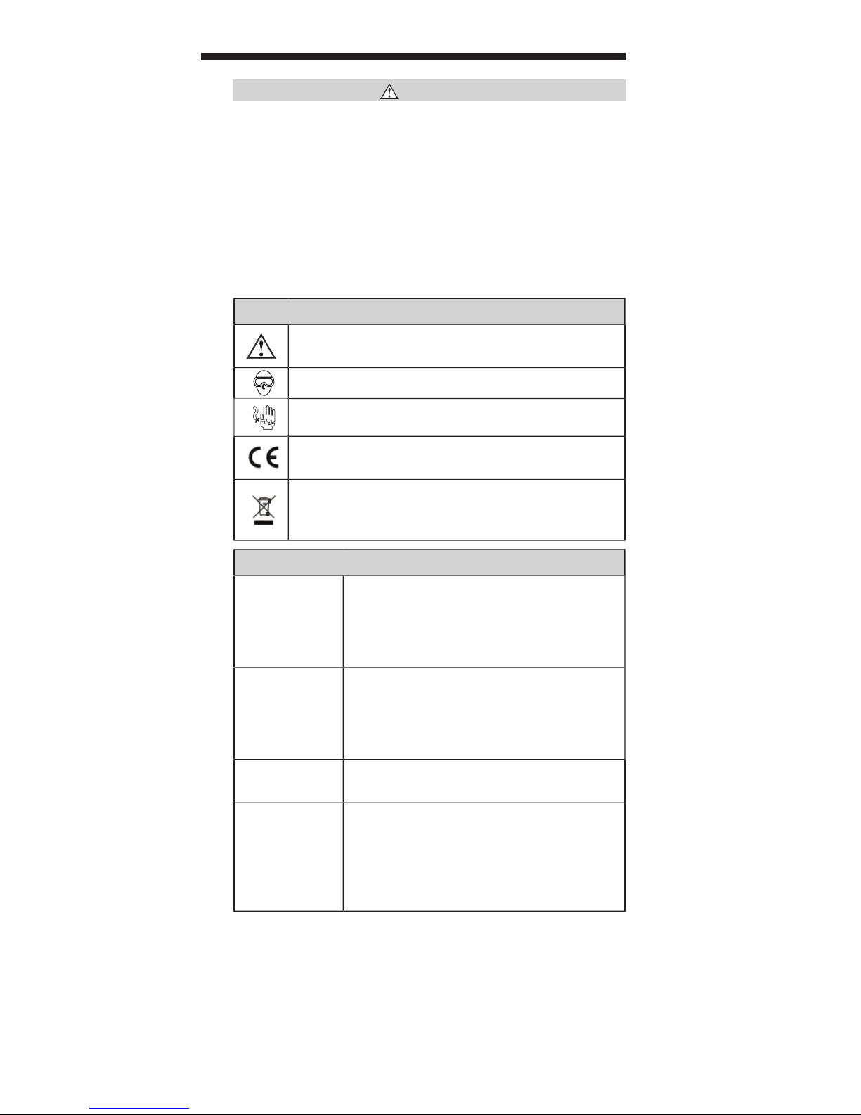
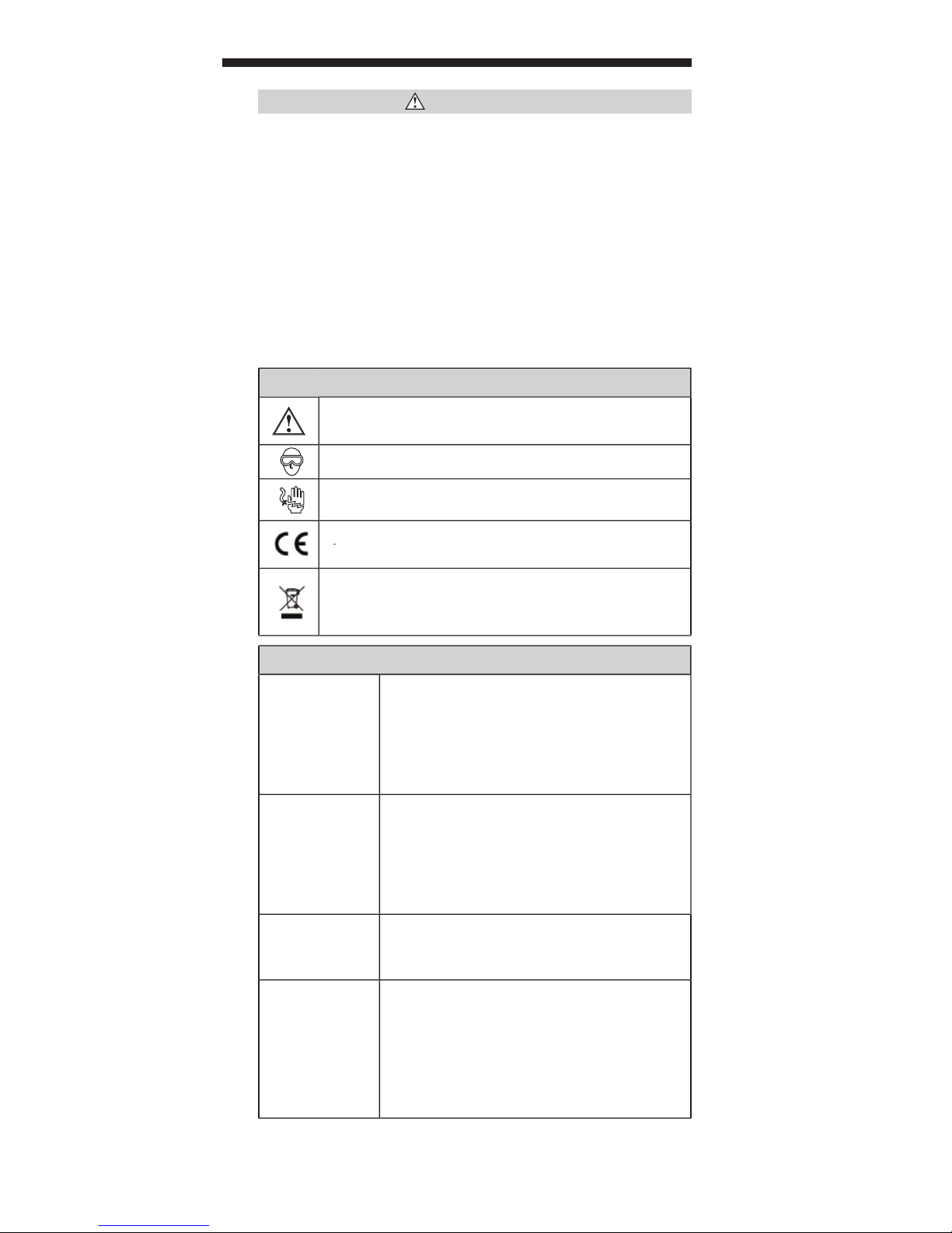
WARNINGS
Voltage range of less than 60V peak AC or DC may pose a safety
Always wear approved eye protection.
Also known as the Velocity of Propagation
Voltage (SELV)
An F-Connector is a common connector for a
transmit small signals in high noise environments.
technology, TDR-SS allows for a length test on
Page 4

ENGLISH
RangerTM TDR
Page 5
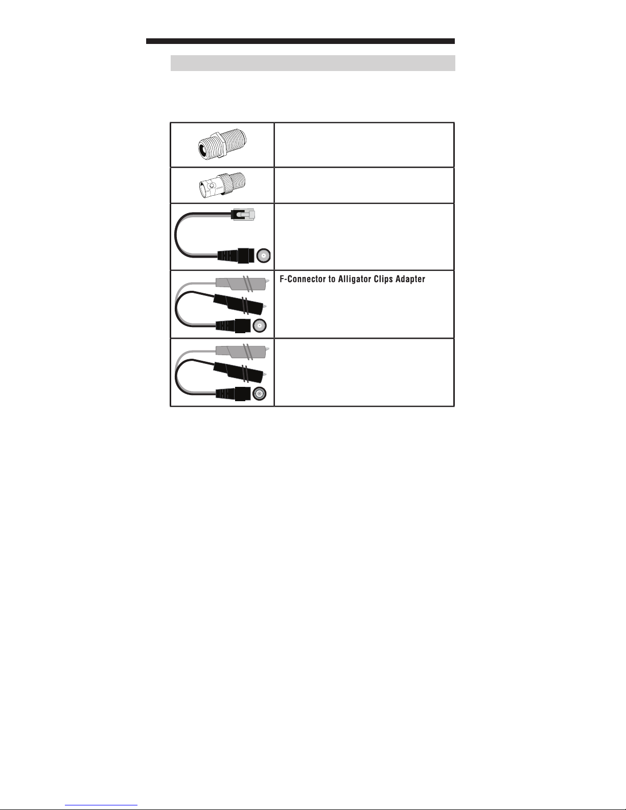
ACCESSORIES
Page 6
ENGLISH
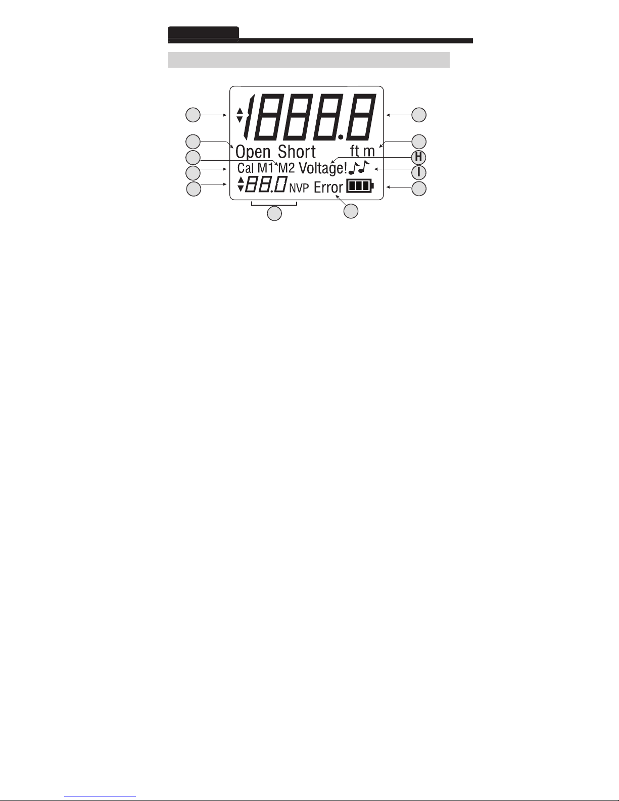
A. Length Adjustment Indicator:
J. Battery Life Indicator:
A
J
Page 7

for testing purposes.
two memory storage locations: M1 and M2.
A long press (two seconds) of the button stores an NVP
value in the selected storage location.
A long press (two seconds) of the Memory and Calibration
value based on an inputted cable length.
A long press (two seconds) of the Calibration button
The Test button initiates length testing on the connected cable.
A short press runs a single test on demand.
A long press (two seconds) of the button starts loop
testing. Pressing any button (except Power) stops loop
testing (or the unit turns off a ft.er 3 minutes).
A short press of the button transmits an audio tone from
the unit through the connected cable.
An analog tone probe (not included) must be used in
A long press (two seconds) of the Power button powers
•
A long press (two seconds) of the button powers off the
Page 8
ENGLISH
AUTO POWER OFF
voltage with a voltage measurement device by a qualified
Connect the F-connector coupler (barrel connector) to the input
The cable to be tested should be terminated with an F-connector
The opposite end of the cable to be tested should be le ft.
Attach the cable to be tested to the Ranger™ TDR by carefully
terminate the cable.
Connect the F-connector coupler (barrel connector) to the input
The cable to be tested should be terminated with a female RJ45
jack on the end that will be attached to the Ranger™ TDR.
The opposite end of the cable to be tested should be le ft.
Attach the included F-connector-to-male-RJ45 plug adapter to the
Attach the RJ45 plug adapter end to the female RJ45 jack of the
Page 9

Connect the F-connector coupler (barrel connector) by carefully
The cable to be tested should have a pair of exposed conductors
that run side-by-side. This includes inner pairs on twisted
The opposite end of the cable to be tested should be le ft. open
Attach the included F-connector to alligator clips adapter to the
Securely attach the alligator clips to the exposed conductors of
the cable to be tested.
Connect the BNC coupler (barrel connector) by carefully screwing
The opposite end of the cable to be tested should be le ft.
Attach the BNC connector of the cable to be tested to the female
Prepare a length of the same type of cable for which you need to
The Ranger™ TDR can calculate an NVP from a test cable length
Determine the physical length of the test cable length. Use the
Connect the test cable length to the Ranger™ TDR as described in
Select the unit of measurement (feet or meters) by pressing and
Enter the known cable length using the Calibration button and Up
Press the Test button. A ft.er a few seconds, the calculated NVP
Press and hold the Memory button to save the new NVP in the
If the calculated NVP is outside of the range 20 to 99.9, the LCD
Page 10
ENGLISH
Use the Up and Down buttons to set the NVP value shown in the
Press the Memory button repeatedly to toggle between memory
Press and hold the Memory button. The up and down arrows
Recall a stored value by pressing the Memory button until the
Page 11

tested should be le ft. open on the opposite end from the tester.
A cable
Attach the cable to be tested as instructed in Preparing to Test
Note that the connection to the cable to be tested should be as
Determine the correct NVP value for the cable to be tested as
Change the unit of measurement if necessary by pressing and
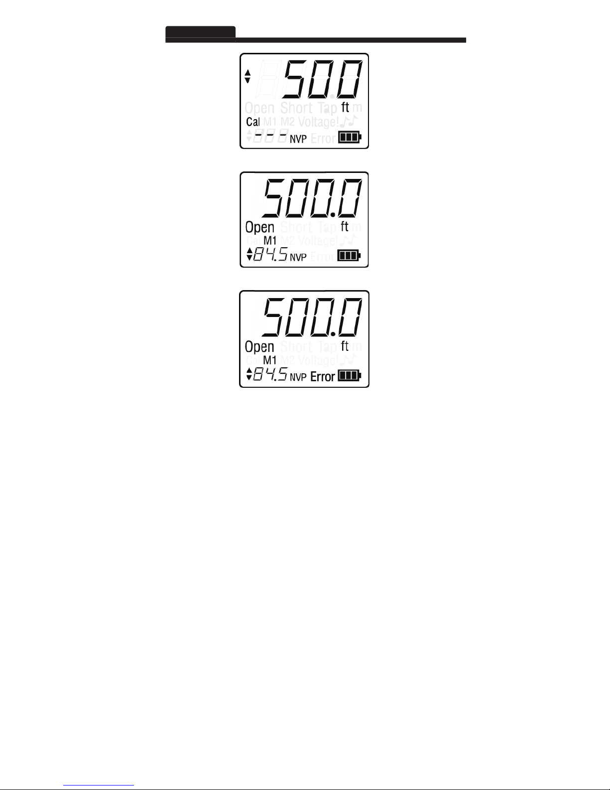
The screen will display “Short” if the two conductors are directly
The screen will display “Open” if the two conductors are not
them. This is the normal condition for performing length testing.
The screen will display “Error” and show dashes instead of the
the cable is improperly terminated or there has been excessive
Page 12
ENGLISH
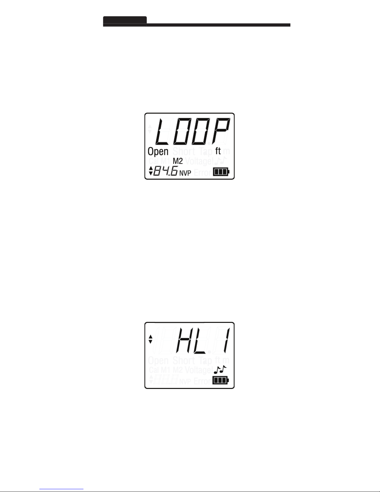
The screen will momentarily flash “LOOP”, then run a test every
two seconds and display the results.
Pressing any other button except the Power button exits
from the unit through a connected cable. The cadence can only be
Attach the cable to be toned as instructed in Preparing to Test
Press the Up button or Down button to switch cadences (HI, LO,
Use a tone probe to trace the cable being toned.
See the tone probe's instruction manual for more information on
Page 13
Coaxial Cable
Phone Cable
Data Cable
Electrical Cable
Security Cable
Page 14
www.kleintools.com
ENGLISH
www.kleintools.com/warranty
time. Do not expose to high temperatures or humidity. A ft.er a period of storage
Page 15

ESPAÑOL
VDV501-090
ADMINISTRADOR
MANUAL DE INSTRUCCIONES
TDR
Page 16

ESPAÑOL
Almacena hasta dos valores de NVP.
Verificaciones automáticas de voltaje previas a las pruebas.
6,8" × 3,15" × 1,3" (17,3cm × 8,0cm × 3,3 cm)
12,0oz (340g) con baterías
32°F a 122°F (0°C a 50°C)
-4°F a 140°F (-20°C a 60°C)
10% a 90%, sin condensación
Altitud:
10000pies (3050m) como máximo
Advertencia de voltaje:
en los límites máximos de voltaje extra bajo
aproximadamente 4V
4 baterías alcalinas AA
Reflectometría de dominio temporal con
amplitud de salida constante de 3Vpp,
Page 17
ADVERTENCIAS
Advertencia: posibilidad de lesiones personales.
Área Económica Europea.
Velocidad
yvelocidad de propagación de onda, la NVP
Voltaje extra
temporal
Page 18

ESPAÑOL
RangerTM TDR
Page 19

ACCESORIOS
Acoplador de conector F a conector cilíndrico
Acoplador de conector F a conector BNC
Adaptador de conector F a conector RJ45
Adaptador de conector F a pinzas tipo cocodrilo
Adaptador de conector BNC a pinzas
tipococodrilo
Page 20

ESPAÑOL
A. Indicador de ajuste de longitud:
voltaje por encima de la clasificación SELV de 60V CA o CD
J. Indicador de la vida útil de la batería:
A
J
Page 21

Arriba/Abajo
Al presionar brevemente el botón Memory (Memoria),
Al presionar el botón por tiempo prolongado (dos segundos),
Al presionar simultáneamente los botones Memory
valor de NVP según la longitud de cable ingresada.
Al presionar brevemente el botón Calibration (Calibración), se
Al presionar el botón Calibration (Calibración) por tiempo
Al presionar brevemente el botón, se ejecuta una sola
Al presionar el botón por tiempo prolongado (dos segundos),
Al presionar brevemente el botón, se transmite un tono de
Al presionar varias veces el botón Tone (Tono), se alterna
Al presionar el botón de encendido por tiempo prolongado
•
Al presionar varias veces el botón, se alterna entre la activación
y desactivación de la retroiluminación.
Al presionar el botón por tiempo prolongado (dos segundos),
Page 22

ESPAÑOL
ARRANQUE Y APAGADO
APAGADO AUTOMÁTICO
Antes de comenzar a trabajar con el Ranger™ TDR, un profesional
fuente de voltaje.
Conecte el acoplador del conector F (conector cilíndrico) al puerto
El cable que desea probar debe terminar con un conector F en el
El otro extremo del cable que desea probar se debe dejar sin terminación
Conecte el cable que desea probar en el Ranger™ TDR
Conecte el acoplador del conector F (conector cilíndrico) al puerto
El cable que desea probar debe terminar con un conector RJ45
El otro extremo del cable que desea probar se debe dejar sin terminación
Conecte el adaptador de conector F a conector RJ45 macho
Conecte el extremo del adaptador del conector RJ45 al conector
Page 23

Conecte el acoplador del conector F (conector cilíndrico) enroscándolo
El cable que desea probar debe tener un par de conductores
El otro extremo del cable que desea probar se debe dejar abierto
Conecte el adaptador de conector F a pinzas tipo cocodrilo
Conecte firmemente las pinzas tipo cocodrilo a los conductores
Conecte el acoplador BNC (conector cilíndrico) enroscándolo
El otro extremo del cable que desea probar se debe dejar sin
terminación O debe terminar con un conector BNC pero se debe
Acople el conector BNC del cable que desea probar al conector
Prepare una longitud del mismo tipo de cable para el que necesita
El Ranger™ TDR puede calcular un valor de NVP a partir de la longitud
Determine la longitud física del cable de prueba. Utilice las
Conecte el cable de prueba al Ranger™ TDR como se describe en
Seleccione la unidad de medida (pies o metros) manteniendo
yCalibration (Calibración).
Ingrese la longitud conocida del cable utilizando el botón Calibration
Presione el botón Test (Probar). Después de unos segundos, el
valor de NVP calculado aparecerá en la esquina inferior izquierda
Mantenga presionado el botón Memory (Memoria) para guardar el
Si el valor de NVP se encuentra fuera del rango de 20 a 99,9,
Page 24

ESPAÑOL
Presione el botón de encendido. La unidad arrancará en el modo
Utilice los botones hacia arriba y hacia abajo para establecer el
valorde NVP que se muestra en la esquina inferior izquierda de
Si mantiene presionado el botón, el valor cambiará más
Almacenamiento del valor de NVP:
El Ranger™ TDR tiene dos ubicaciones de almacenamiento para
Presione el botón Memory (Memoria) varias veces para alternar
Establezca la ubicación de memoria utilizando el procedimiento
Mantenga presionado el botón Memory (Memoria). Las flechas
Para recuperar un valor almacenado, debe presionar el botón
Page 25

Conecte el cable que desea probar según se describe en la
Tenga en cuenta que la conexión al cable que desea probar debe ser
Determine el valor correcto de NVP correspondiente al cable
Establezca el valor de NVP según se describe en la sección
Si es necesario, cambie la unidad de medida manteniendo
yCalibration (Calibración).
La pantalla mostrará “Short” (Cortocircuito) si los dos conductores
La pantalla mostrará “Open” (Circuito abierto) si los dos
La pantalla mostrará “Error” y guiones en lugar de la longitud si
Page 26

ESPAÑOL
En el modo Test (Prueba), mantenga presionado el botón
La señal “LOOP” (Bucle) parpadeará momentáneamente en la
ysemostrarán los resultados.
Para salir del modo Loop (Bucle), presione cualquier botón,
Activación del modo Tone (Tono):
Conecte el cable al que aplicará tono según se describe en la
Presione el botón de tono (representado con dos notas musicales).
Presione el botón hacia arriba o hacia abajo para cambiar las
Utilice una sonda de tono para rastrear el cable al que aplicará tono.
Consulte el manual de instrucciones de la sonda de tono para
Page 27

A continuación se muestra una lista de valores de NVP para tipos de
Cable coaxial
Cable telefónico
Cable de datos
Anaranjado y blanco)
Cable eléctrico
Cable de seguridad
Page 28

www.kleintools.com
ESPAÑOL
y recicle las baterías agotadas.
ANSI/NEDA15A).
www.kleintools.com/warranty
Apague el instrumento y desconecte todos los cables. Limpie el instrumento con
ALMACENAMIENTO
Antes de la eliminación de este producto, comuníquese con Klein
Page 29

PORTUGUÊS
VDV501-090
MANUAL DE INSTRUÇÕES
Page 30

PORTUGUÊS
Armazena até dois valores da NVP.
vídeo, fio de lâmpada, siamês e cabo NM.
Verificações automáticas de tensão de antes do teste.
6,8" x 3,15" x 1,3" (17,3 x 8,0 x 3,3 cm)
12,0 oz (340 gramas) com baterias
32 °F a 122 °F (0 °C a 50 °C)
-4 °F a 140 °F (-20 °C a 60 °C)
10% a 90%, sem condensação
Altitude:
Máxima de 10 000 pés (3050 m)
Advertência de tensão:
No máximo dos limites máximos de
A medição continua enquanto a advertência é exibida.
Aproximadamente 4 V
Baterias alcalinas 4 AA
Ativa:
Reflectometria no domínio do tempo
com NVP
Amplitude de saída constante de 3 Vpp,
Page 31

ADVERTÊNCIAS
faixa pode ser um risco de segurança ao usuário e ao instrumento.
Advertência: Existe risco potencial de acidente pessoal.
Velocidade
transmitir sinais pequenos em ambientes com
Page 32

PORTUGUÊS
RangerTM TDR
Page 33

ACESSÓRIOS
Acoplador de conector de tambor de conector F
Acoplador de conector F para conector BNC
Adaptador de conector F para tomada RJ45
Adaptador de conector F para clipes jacaré
Adaptador de conector BNC para clipes jacaré
Page 34

PORTUGUÊS
A. Indicador de ajuste de comprimento:
J. Indicador da vida útil da bateria:
A
J
Page 35

valores da NVP para fins de teste.
•
Page 36

PORTUGUÊS
A unidade executa imediatamente um teste de comprimento ao ligar.
Conecte o acoplador do conector F (conector de tambor) à porta
O cabo a ser testado deve ter um conector F como terminador
A extremidade oposta do cabo a ser testado deve estar sem
terminador OU ter um conector F, mas deve estar desconectada.
Conecte o cabo a ser testado no TDR Ranger™ rosqueando
Conecte o acoplador do conector F (conector de tambor) à porta
O cabo a ser testado deve ter uma tomada RJ45 fêmea como
terminador na extremidade a ser conectada no TDR Ranger™.
A extremidade oposta do cabo a ser testado deve estar sem
terminador OU ter um plugue ou uma tomada RJ45, mas deve estar
Conecte o adaptador de conector F para plugue RJ45 incluído
Conecte a extremidade do adaptador para plugue RJ45 à tomada
Page 37

Conecte o acoplador do conector F (conector de tambor)
O cabo a ser testado deve ter um par de condutores expostos
A extremidade oposta do cabo a ser testado deve ficar aberta
Conecte o adaptador de conector F para clipes jacaré incluído
Prenda bem os clipes jacaré nos condutores expostos do cabo
Conecte o acoplador para BNC (conector de tambor)
A extremidade oposta do cabo a ser testado deve estar sem
terminador OU ter um conector BNC, mas deve estar desconectada.
Conecte o conector BNC do cabo a ser testado ao conector BNC
fêmea do TDR Ranger™.
A NVP pode ser estimada com base no tipo de cabo (RG6, Cat5e
A NVP pode ser calculada a partir de um comprimento conhecido
Prepare um comprimento do mesmo tipo de cabo cuja NVP
O TDR Ranger™ pode calcular a NVP a partir de um comprimento
Determine o comprimento físico do comprimento do cabo
Conecte o comprimento do cabo de teste ao TDR Ranger™
Selecione a unidade de medida (pés ou metros) pressionando e
Insira o comprimento conhecido do cabo usando o botão de
Pressione o botão de teste. Após poucos segundos, o valor
Pressione e mantenha pressionado o botão de memória para
Se o valor calculado da NVP estiver fora da faixa de 20 a 99,9,
Page 38

PORTUGUÊS
AJUSTE DOS VALORES DA NVP
forneça medição precisa do comprimento.
Ajuste manual da NVP:
Pressione o botão liga/desliga. A unidade inicia no modo de teste.
Use os botões para cima e para baixo para ajustar o valor da NVP
Pressionar e manter pressionado o botão altera o valor com
O TDR Ranger™ possui dois locais para armazenar valores da NVP.
Pressione o botão de memória repetidamente para alternar entre
Defina o local de memória usando o procedimento acima descrito.
Pressione e mantenha pressionado o botão de memória. As setas
Recupere um valor armazenado pressionando o botão
Page 39

Assim que o valor da NVP do cabo tiver sido definido, o comprimento
Conecte o cabo a ser testado conforme as instruções da seção
Observe que a conexão ao cabo a ser testado deve ser a mais curta
Determine o valor correto da NVP do cabo a ser testado conforme
Ajuste o valor da NVP conforme as instruções na seção Ajuste
Ligue a unidade pressionando o botão liga/desliga.
Altere a unidade de medida conforme necessário pressionando
A tela exibirá “Short” (Em curto) se os dois condutores estiverem
A tela exibirá “Open” (Aberto) se os dois condutores não
tiver resistência alta. Essa é a condição normal para realizar
A tela exibirá “Error” (Erro) e serão exibidos traços em vez do
Page 40

PORTUGUÊS
Enquanto estiver no modo de teste, pressione e mantenha
A tela pisca temporariamente “LOOP”, em seguida executa
Pressionar qualquer outro botão, exceto o botão liga/desliga,
APLICAÇÃO DE TOM NO CABO
Ativação do modo de tom:
Conecte o cabo em que o tom será aplicado conforme
Pressione o botão para cima ou para baixo para mudar
Use uma sonda de tom para rastrear o cabo em que o tom está
Consulte o manual de instruções da sonda de tom para obter
Page 41

Cabo coaxial
Cabo de telefone
Cabo de dados
Cabo elétrico
Cabo de segurança
Page 42

www.kleintools.com
ATENDIMENTO AO CLIENTE
PORTUGUÊS
www.kleintools.com/warranty
ARMAZENAMENTO
Após um período de armazenamento em condições extremas que excedam
Antes do descarte deste produto, entre em contato com a Klein Tools
Page 43

FRANÇAIS
VDV501-090
MANUEL D’UTILISATION
TDR
Page 44

FRANÇAIS
trouve les défaillances dans les câbles et possède un générateur de
tonalitéintégré pour le repérage des câbles.
Affiche la lecture de la longueur en pieds ou en mètres.
Vérifications automatiques de tension avant les tests.
17,3 x 8,0 x 3,3cm (6,8 x 3,15 x 1,3po)
340grammes (12,0oz) avec les piles
0 à 50°C (32 à 122°F)
-20 à 60°C (-4 à 140°F)
10% à 90%, sans condensation
Altitude:
3050m (10000pi) maximum
Avertissement de tension
au niveau de sécurité maximal, à la limite
environ 4V
4piles alcalinesAA
Actif:
réflectométrie temporelle à spectre étalé
amplitude de sortie constante de 3V crête
Page 45

AVERTISSEMENTS
Avertissement: l’utilisation de cet appareil comporte
Vitesse de
Aussi connu sous les noms Vitesse de
tension de
temporelle à
Page 46

FRANÇAIS
RangerTM TDR
Page 47

ACCESSOIRES
Adaptateur à connecteur F vers RJ45
Adaptateur à connecteur F vers pinces crocodile
Adaptateur à connecteur BNC vers
Page 48

FRANÇAIS
A. Indicateur de l’ajustement de la longueur:
tonalité peut être modifiée dans le mode Tonalité.
J. Indicateur de durée de vie de piles:
A
J
Page 49

valeurs NVP à des fins de test.
valeur NVP en fonction de la longueur de câble entrée.
Alimentation
Alimentation met le
Appuyer de nouveau sur le bouton active ou désactive
Alimentation met le Ranger™ TDR hors tension.
Page 50

FRANÇAIS
Appuyez et maintenez enfoncé le bouton d’alimentation pour
Appuyez et maintenez enfoncé le bouton d’alimentation pour
ARRÊT AUTOMATIQUE
Connectez le connecteur d’accouplement en F (connecteur
Le câble à tester doit se terminer par un connecteur en F à
L’extrémité opposée du câble à tester ne doit pas comporter de
Fixez le câble à tester au Ranger™ TDR en vissant délicatement ou
Connectez le connecteur d’accouplement en F (connecteur
Le câble à tester doit se terminer par un connecteur RJ45 femelle
L’extrémité opposée du câble à tester ne doit pas comporter
Fixez l’adaptateur de connecteur en F vers prise RJ45 mâle au
Fixez l’extrémité de l’adaptateur avec la fiche RJ45 à la prise
Page 51

Raccordez le connecteur d’accouplement en F (connecteur
Le câble à tester doit se terminer par une paire de conducteurs
L’extrémité opposée du câble à tester devrait être ouverte
Fixez l’adaptateur de connecteur en F vers pinces crocodile au
Fixez solidement les pinces crocodile aux conducteurs exposés
Raccordez le connecteur d’accouplement BNC (connecteur
L’extrémité opposée du câble à tester ne doit pas comporter de
Fixez le connecteur BNC au câble à tester au connecteur BNC
femelle du Ranger™ TDR.
techniques du câble ou en communiquant avec le fabricant.
Préparez un segment du même type de câble pour lequel vous
Le Ranger™ TDR peut calculer une NVP à partir d’un segment
test plus longs offriront des résultats plus exacts. L’utilisation
Déterminez la longueur physique du segment de câble test.
Raccordez le segment de câble à tester au Ranger™ TDR de la
façon décrite dans la section «Préparation du test de câble».
Appuyez sur le bouton Alimentation sur le Ranger™ TDR.
Appuyez sur le bouton Cal.
Sélectionnez l’appareil de mesure (pieds ou mètres) en appuyant
Entrez la longueur connue du câble à l’aide du bouton Cal et des
vous les enfoncez.
Appuyez sur le bouton Test. Après quelques secondes, la NVP
Appuyez sur le bouton Mem et maintenez-le enfoncé pour
Si la valeur NVP calculée n’est pas dans la plage de 20 à 99,9,
Page 52

FRANÇAIS
Appuyez sur le bouton Alimentation. L’appareil démarre en
Utilisez les boutons Haut et Bas pour régler la valeur NVP affichée
Maintenez un bouton enfoncé pour modifier la valeur plus
Le Ranger™ TDR comprend deux emplacements pour
Appuyez sur le bouton Mem à plusieurs reprises pour basculer
Sélectionnez un emplacement mémoire en suivant la procédure
Appuyez sur le bouton Mem et maintenez-le enfoncé. Les flèches
valeur aura été enregistrée.
Affichez à l’écran une valeur enregistrée en appuyant sur le bouton
Page 53

testeur doit être ouverte (non raccordée).
Connectez le câble à tester de la manière indiquée dans la section
La connexion entre l’appareil et le câble à tester doit être aussi
Déterminez la valeur NVP exacte pour le câble à tester, en suivant
Réglez la valeur NVP en suivant les instructions de la section
Allumez l’appareil en appuyant sur le bouton Alimentation.
Au besoin, changez l’appareil de mesure en appuyant simultanément
Appuyez sur le bouton Test une seule fois. Après un moment,
L’écran affiche «Short» (Court-circuit) si les deux conducteurs
L’écran affiche «Open» (Circuit ouvert) si les deux conducteurs
L’écran affiche «Error» et des traits horizontaux plutôt
Page 54

FRANÇAIS
vous permet de tester plusieurs câbles successivement sans avoir
L’écran fait clignoter le mot LOOP (Boucle) momentanément, puis
Appuyer sur un bouton autre que le bouton Alimentation permet
Activation du mode Tonalité:
Connectez le câble que vous souhaitez localiser à l’aide du
Appuyez sur le bouton Alimentation.
Appuyez sur le bouton Tonalité (icône représentant deux notes
Appuyez sur les boutons Haut et Bas pour sélectionner une
Utilisez une sonde de tonalité pour localiser le câble utilisé pour
transmettre la tonalité.
Pour de plus amples renseignements sur la localisation d’un
Page 55

Vous trouverez ci-dessous la liste des valeurs NVP pour les types de câbles
Câble coaxial
Câble téléphonique
Câble de données
Câble électrique
Câble de sécurité
Page 56

www.kleintools.com
FRANÇAIS
Rev. 01/15 D
À l’arrière du Ranger™ TDR
1. Retirez le couvercle du
ANSI/NEDA 15A).
www.kleintools.com/warranty
Avant d’éliminer ce produit, veuillez communiquer avec Klein Tools
 Loading...