

Page 1

Auto-Ranging Multimeter
ENGLISH
INSTRUCTION MANUAL
• IP67: DUSTPROOF & WATERPROOF
MM500
• USER-FRIENDLY
• AUDIBLE / VISUAL CONTINUITY
• RESISTANCE RANGE
• AUTO RANGING
• AUTO HOLD
• BACK LIGHT
• LEAD HOLDER
• 3-3/4 DIGIT 4000 COUNT LCD
750V
Apo
A-HOLD
Page 2

GENERAL SPECIFICATIONS
WARNINGS
The Klein Tools MM500 is an auto-ranging multimeter.
It measures AC/DC voltage, resistance, and continuity.
• Operating Altitude: 2,000 m (6,562 ft.)
• Relative Humidity: 75% max operating
• Operating Temperature:
O°to 50°C (32°to 122°F) < 75% R.H.
• Storage Temperature:
-20°to 60°C (-4° to 140°F) < 80% R.H.
• Accuracy Temperature:
18° to 28°C (64° to 82°F) < 75% R.H.
• Temperature Coef cient: 0.1*(speci ed accuracy) / °C
• Sampling Frequency: 3 samples per second
• Dimensions: 143 x 76 x 32 mm (5.625" x 3" x 1.25")
• Weight: 184 g (6.5 oz.)
• Calibration: Accurate for one year
• Standards: UL 61010-1, Ed. 2, Revision date 2008/10/28
CSA C22.2 No. 61010-1, Edition 2, Rev. date 2008/10/01
• Pollution Degree: 2
• Accuracy: ± (% of reading + # of least signi cant digits)
• Ingress Protection: IP67 Certi ed
• Drop Protection: 3 m (9.8 ft.)
• Safety Rating: CAT III 750V / CAT IV 600V
• Electromagnetic Environment: EN61326-1:2013 This
equipment meets requirements for use in basic and
controlled electromagnetic environments like residential
properties, business premises, and light-industrial
locations.
Specifications subject to change.
To ensure safe operation and service of the tester,
follow these instructions. Failure to observe these
warnings can result in severe injury or death.
• Never use the meter on a circuit with voltages that
exceed the category based rating of this meter.
• Do not use the meter during electrical storms or
in wet weather.
• Do not use the meter or test leads if they appear
to be damaged.
• Ensure meter leads are fully seated, and keep
fingers away from the metal probe contacts when
making measurements.
• Do not open the meter to replace batteries while
the probes are connected.
• Use caution when working with voltages above
60V DC or 25V AC RMS. Such voltages pose a
shock hazard.
• To avoid false readings that can lead to electrical
shock, replace batteries when a low battery
indicator appears.
• Unless measuring voltage, shut off and lock out
power before measuring resistance.
• Always adhere to local and national safety codes.
Use individual protective equipment to prevent
shock and arc blast injury where hazardous live
conductors are exposed.
• The MM500 is sealed to meet IP67 certification.
There are no user serviceable parts.
SYMBOLS
AC Alternating Current
DC/AC Voltage or Current
Resistance Continuity
Double Insulated Class II
Dangerous levels
SYMBOLS USED ON LCD
AC Measurement DC Measurement
Negative DC Value
-
Apo
k
V
Auto Power-Off Active
Low Battery
Kilo 10
3
Voltage
Measurement
AT
.OL
A- HOLD
Ω
DC Direct Current
Ground
Warning or Caution
Auto Range Active
Continuity Test
Overload:
Range Exceeded
Auto-Hold Active
Resistance
in Ohms
G
F
D
B
FEATURES
Apo
A-HOLD
H
(Back)
E
3C4
21
G
(Back)
A
(Bottom)
Page 3

FEATURE DETAILS
A. Use proper safety-rated leads.
Do not attempt to measure more than 750V.
B. Voltage Select Button
• Auto detect AC or DC
C. Resistance / Continuity Button
• Selects Resistance or Continuity Function
D. Auto Hold
• Press the “A-HOLD" button
• Auto Hold captures the first stable displayed value
until a new stable value is measured. Themeter
will then capture the new value and emit a beep
(V and Ohm functions).
E. Back Light
• Press and hold the “A-Hold" button to enable
or disable lights.
battery significantly.
NOTE: Using lights drains the
F. Auto Power-Off
• Device will power off after 30 minutes non-use.
FUNCTION INSTRUCTIONS
• Press “ V
• APO timer resets when a “ V
” or “ Ω / ” to wake.
” or “ Ω ”
measurement is made.
• Holding the “ V
” or “ Ω / ” button for one
second while turning on disables Auto PowerOff.
G. Battery / Replacement
• When indicator is displayed on the LCD,
batteries must be replaced.
• Remove back screws and replace 2 x AAA
batteries.
H. Probe Storage / Receptacle Testing
• To store probes, ensure the collar of the probe
fits the probe holder channel and press down.
• When testing receptacles, slide the probes into
the probe holder from the top of the unit. The
probe holder is designed to space the probes for
easy testing of receptacles.
1. AC Voltage: <750V
A-HOLD
RED LEAD
2. DC Voltage: <750V
A-HOLD
RED LEAD
3. Resistance: < 4KΩ.
BLACK LEAD
BLACK LEAD
• With the unit OFF or in “ Ω ” mode, press the “ V ” button
Apo
A-HOLD
for voltage. Unit defaults to AC Voltage.
• Attach RED lead to “ V Ω ” input, BLACK lead to COM.
• Display auto detects and shows AC voltage.
• Power the unit OFF by holding the “ V ” or “ Ω /
” button
for one second.
• With the unit OFF or in “ Ω ” mode, press the “ V ” button
for voltage. Unit defaults to AC Voltage.
A-HOLD
• Attach RED lead to “ V Ω ” input, BLACK lead to COM.
• Display auto detects and shows DC voltage.
• Power the unit OFF by holding the “ V ” or “ Ω /
” button
for one second.
A-HOLD
RED LEAD
BLACK LEAD
• DO NOT attempt to measure resistance on a live circuit.
Apo
A-HOLD
• With the unit OFF or in “ V ” mode, press the “ Ω /
button once for resistance.
”
• Attach RED lead to “ V Ω ” input, BLACK lead to COM.
• Display shows resistance.
• Power the unit OFF by holding the “ V ” or “ Ω /
” button
for one second.
Page 4

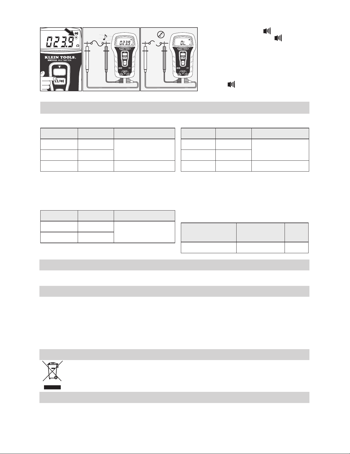
4. Continuity
Apo
A-HOLD
RED LEAD
BLACK LEAD
• Press the “Ω / ” button to select
Apo
A-HOLD
Apo
A-HOLD
continuity. The “
in the LCD.
• Buzzer sounds and RED indication light
RED LEAD
BLACK LEAD
illuminates if reading is less than 25 Ω.
• Power the unit OFF by holding the “ V ”
or “Ω /
ELECTRICAL SPECIFICATIONS
” symbol will appear
” button for one second.
DC Voltage Measurement
Range Resolution Accuracy
± 1 to 399.9
0.1V
± (0.5% + 3 digits)
± 400 to 599
± 600 to 750
1V
1V
± (0.5% + 5 digits)
Overload Protection: 750V
Input Impedance: >10MΩ
Resistance Measurement (Ohms)
Range Resolution Accuracy
0 to 399 0.1Ω
± (0.8% + 4 digits)
0.4k to 4kΩ 0.001KΩ
Overload Protection: 600V
www.kleintools.com/warranty
AC Voltage Measurement
Range Resolution Accuracy
1 to 399.9 0.1V
400 to 599 1V
600 to 750 1V
Overload Protection: 750V
Frequency: 50 to 60 Hz
Input Impedance: >10MΩ
Response: Averaging
Continuity Test
Overload
Protection
600V Appx. 0.44V < 25Ω
WARRANTY
± (1.2% + 5 digits)
± (1.2% + 8 digits)
Open Circuit
Voltage
Tone
CLEANING AND STORAGE
Turn instrument off and disconnect test leads. Clean the instrument by using a damp cloth. Do not use
abrasive cleaners or solvents.
Remove the batteries when instrument is not in use for a prolonged period of time. Do not expose to high
temperatures or humidity. After a period of storage in extreme conditions exceeding the limits mentioned in
the Specifications section, allow the instrument to return to normal operating conditions before using it.
DISPOSAL / RECYCLE
Do not place equipment and its accessories in the trash. Items must be properly disposed of in
accordance with local regulations.
CUSTOMER SERVICE
KLEIN TOOLS, INC.
450 Bond Street
Lincolnshire, IL 60069
customerservice@kleintools.com
1-877-775-5346
www.kleintools.com
Page 5

ESPAÑOL
MANUAL DE INSTRUCCIONES
• IP67: A PRUEBA DE POLVO Y AGUA
MM500
• FÁCIL DE USAR
• CONTINUIDAD POR INDICADOR
VISUAL Y AUDIBLE
• RANGO DE RESISTENCIA
• RANGO AUTOMÁTICO
• AUTORETENCIÓN
• RETROILUMINACIÓN
• PORTACABLES
• PANTALLA LCD DE 3-3/4 DÍGITOS
CON RECUENTO DE 4000
750 V
Apo
A-HOLD
Page 6

ESPECIFICACIONES GENERALES
ADVERTENCIAS
El MM500 de Klein Tools es un multímetro de rango automático.
Mide voltaje CA/CD, resistencia y continuidad.
• Altitud de funcionamiento: 2.000m (6.562pies)
• Humedad relativa: 75 % máx., en funcionamiento
• Temperatura de operación:
0°C a 50°C (32°F a 122°F) < 75% H.R.
• Temperatura de almacenamiento:
-20°C a 60°C (-4°F a 140°F) < 80% H. R.
• Temperatura de precisión:
18°C a 28°C (64°F a 82°F) < 75% H. R.
• Coe ciente de temperatura: 0,1*(precisión especi cada)/°C
• Frecuencia de muestreo: 3 muestras por segundo
• Dimensiones: 143 mm × 76 mm × 32 mm (5,625" × 3" × 1,25")
• Peso: 184g (6,5oz)
• Calibración: precisa durante un año
• Normas:
CSA C22.2 N.º 61010-1, 2.
• Grado de contaminación: 2
• Precisión: ± (% de lectura + cantidad de dígitos menos
signi cativos)
• Protección contra el ingreso de objetos sólidos y líquidos:
Certi cación IP67
• Protección ante caídas: 3m (9,8pies)
• Clasi cación de seguridad: CAT III 750V, CAT IV 600V
• Entorno electromagnético: Norma N61326-1:2013: este
equipo cumple con los requisitos apropiados para su uso
en entornos electromagnéticos básicos y controlados como
propiedades residenciales, establecimientos comerciales e
instalaciones de industria ligera.
Especificaciones sujetas a cambios.
UL 61010-1, 2.da ed., fecha de revisión 28/10/2008
da
edición, fecha de revisión 01/10/2008
Para garantizar un funcionamiento y servicio seguros del
probador, siga estas instrucciones. El incumplimiento de
estas advertencias puede provocar lesiones graves o la
muerte.
• Nunca debe utilizar este multímetro en un circuito
• No utilice el multímetro durante tormentas eléctricas
• No utilice el multímetro o los cables de prueba si en
• Asegúrese de que los cables del multímetro estén
• No abra el multímetro para reemplazar las baterías
• Proceda con precaución cuando trabaje con voltajes
• Para evitar lecturas falsas que puedan provocar
• A menos que esté midiendo voltaje, apague y bloquee
• Cumpla siempre con los códigos de seguridad
• El multímetro MM500 está sellado para satisfacer
SÍMBOLOS
con voltajes que excedan la clasificación basada en
categorías del multímetro.
o en clima húmedo.
apariencia están dañados.
correctamente colocados y mantenga los dedos lejos
de los contactos de la sonda de metal al realizar las
mediciones.
mientras las sondas están conectadas.
superiores a 60V CD o 25V CA RMS. Esos voltajes
implican un riesgo de descarga.
descarga eléctrica, reemplace las baterías cuando
aparezca el indicador de batería baja.
la energía antes de medir resistencia.
locales y nacionales. Utilice equipo de protección
individual para prevenir lesiones por descarga y arco
eléctrico en los lugares donde haya conductores
activos peligrosos expuestos.
los requisitos de certificación IP67. Incluye piezas no
reparables por el usuario.
Corriente alterna CA Corriente directa CD
Voltaje o corriente
CD/CA
Resistencia Continuidad
Doble aislamiento
Clase II
Niveles peligrosos
Conexión a tierra
Advertencia o
precaución
SÍMBOLOS QUE SE UTILIZAN EN LA
PANTALLA LCD
Medición de CA Medición de CD
Valor negativo de CD
-
Apagado automático
Apo
activo
Batería baja
3
kilo 10
k
Medición
V
de voltaje
A- HOLD
Rango automático
AT
activo
Prueba de
continuidad
Sobrecarga:
.OL
rango excedido
Autorretención activa
Resistencia
Ω
en ohmios
G
F
D
B
FUNCIONES
Apo
21
A-HOLD
H
(Parte posterior)
E
3C4
G
(Parte posterior)
A
(Parte inferior)
Page 7

DETALLES DE LAS CARACTERÍSTICAS
A. Utilice cables con una clasi cación
deseguridad adecuada.
No intente medir más de 750V.
B. Botón de selección de voltaje
• Detecta automáticamente CA o CD
C. Botón de resistencia / continuidad
• Selecciona la función de resistencia o continuidad
D. Autorretención
• Presione el botón "A-HOLD"
• La función de autorretención captura el primer valor
estable que se muestra, hasta que se mida un nuevo
valor estable. Entonces el multímetro capturará
el nuevo valor y emitirá una indicación sonora
(funciones V y Ohmios).
E. Retroiluminación
• Mantenga presionado el botón "A-Hold" para activar
y desactivar las luces.
descarga las baterías considerablemente.
NOTA: El uso de las luces
F. Apagado automático
• El dispositivo se apagará automáticamente después
de 30 minutos de no utilizarlo.
INSTRUCCIONES Y FUNCIONES
• Presione “ V ” o “ Ω /
” para encenderlo.
• El temporizador APO se reconfigura cuando se
realiza una medición de “ V ” o “ Ω ”.
• Si mantiene presionado el botón “ V ” o “ Ω /
”
por un segundo durante el encendido, se activará el
Apagado automático.
G. Batería / Reemplazo
• Cuando aparece el indicador
en la pantalla LCD,
se deben reemplazar las baterías.
• Quite los tornillos de la parte posterior y reemplace
las 2 baterías AAA.
H. Almacenamiento de sondas / Prueba de
receptáculos
• Para almacenar sondas, asegúrese de que el collarín
de la sonda se adapte al canal portasondas y
presione.
• Cuando realice pruebas de sondas, deslice las
sondas en el portasondas desde la parte superior
de la unidad. El portasondas ha sido diseñado para
espaciar las sondas de modo que sea fácil probar
los receptáculos.
1. Voltaje CA: < 750V
A-HOLD
CABLE ROJO
2. Voltaje CD: < 750V
A-HOLD
CABLE ROJO
3. Resistencia: < 4kΩ.
A-HOLD
CABLE ROJO
CABLE NEGRO
CABLE NEGRO
CABLE NEGRO
• Con la unidad apagada o en modo “ Ω ”, presione el botón “ V ”
Apo
A-HOLD
para el voltaje. El valor predeterminado de la función de voltaje
de la unidad es CA.
• Conecte el cable ROJO en la entrada “ V Ω ” y el cable NEGRO
en la entrada COM.
• La pantalla detecta y muestra el voltaje CA automáticamente.
• Apague la unidad presionando el botón “ V ” o “ Ω /
”
durante un segundo.
• Con la unidad apagada o en modo “ Ω ”, presione el botón “ V ”
para el voltaje. El valor predeterminado de la función de voltaje
de la unidad es CA.
A-HOLD
• Conecte el cable ROJO en la entrada “ V Ω ” y el cable NEGRO
en la entrada COM.
• La pantalla detecta y muestra el voltaje CD automáticamente.
• Apague la unidad presionando el botón “ V ” o “ Ω /
”
durante un segundo.
•
NO intente medir resistencia en un circuito activo.
Apo
A-HOLD
• Con la unidad apagada o en modo “ V ”, presione el botón
“ Ω /
” una vez para resistencia.
• Conecte el cable ROJO en la entrada “ V Ω ” y el cable NEGRO
en la entrada COM.
• La pantalla muestra la resistencia.
• Apague la unidad presionando el botón “ V ” o “ Ω /
”
durante un segundo.
Page 8

4. Continuidad
Apo
A-HOLD
CABLE ROJO
CABLE NEGRO
• Presione el botón “Ω / ” para
Apo
A-HOLD
Apo
A-HOLD
seleccionar continuidad. En la pantalla
LCDaparecerá el símbolo “
• Suena el zumbador y se ilumina el indicador
de luz color ROJO si la lectura es inferior a
25Ω.
CABLE ROJO
CABLE NEGRO
• Apague la unidad presionando el botón
“V” o “Ω /
ESPECIFICACIONES ELÉCTRICAS
”.
” durante un segundo.
Medición de voltaje de CD
Rango Resolución Precisión
± 1 a 399,9
0,1V
± (0,5% + 3 dígitos)
± 400 a 599
± 600 a 750
1V
1V
± (0,5% + 5 dígitos)
Protección contra sobrecarga: 750V
Impedancia de entrada: > 10MΩ
Medición de resistencia (ohmios)
Rango Resolución Precisión
0 a 399 0,1Ω
± (0,8% + 4 dígitos)
0,4k a 4kΩ 0,001kΩ
Protección contra sobrecarga: 600V
www.kleintools.com/warranty
Medición de voltaje de CA
Rango Resolución Precisión
1 a 399,9 0,1V
400 a 599 1V
600 a 750 1V
Protección contra sobrecarga: 750V
Frecuencia: 50Hz a 60 Hz
Impedancia de entrada: > 10MΩ
Respuesta: Promedio
Prueba de continuidad
Protección contra
sobrecarga
600V Aprox. 0,44V < 25Ω
GARANTÍA
± (1,2% + 5 dígitos)
± (1,2% + 8 dígitos)
Voltaje de
circuito abierto
Tono
LIMPIEZA Y ALMACENAMIENTO
Apague el instrumento y desconecte los cables de prueba. Limpie el instrumento con un paño húmedo.
Noutilice solventes ni limpiadores abrasivos.
Retire las baterías si no va a utilizar el instrumento durante un tiempo prolongado. No lo exponga a la
humedad ni a altas temperaturas. Luego de un período de almacenamiento en condiciones extremas que
sobrepasen los límites mencionados en la sección Especificaciones, deje que el instrumento vuelva a las
condiciones de funcionamiento normales antes de utilizarlo.
ELIMINACIÓN/RECICLAJE
No arroje el equipo ni sus accesorios a la basura. Los elementos se deben desechar
correctamente de acuerdo con las regulaciones locales.
SERVICIO AL CLIENTE
KLEIN TOOLS, INC.
450 Bond Street
Lincolnshire, IL 60069, EE. UU.
customerservice@kleintools.com
1-877-775-5346
www.kleintools.com
Page 9

PORTUGUÊS
MANUAL DE INSTRUÇÕES
• IP67: À PROVA DE POEIRA E ÁGUA
MM500
• FÁCIL UTILIZAÇÃO
• CONTINUIDADE VISUAL/SONORA
• FAIXA DE RESISTÊNCIA
• MUDANÇA DE FAIXA AUTOMÁTICA
• RETENÇÃO AUTOMÁTICA
• LUZ DE FUNDO
• SUPORTE DE PONTAS DE PROVA
• DISPLAY LCD COM 3-3/4 DÍGITOS
E4000 CONTAGENS
750 V
Apo
A-HOLD
Page 10

ESPECIFICAÇÕES GERAIS
ADVERTÊNCIAS
O MM500A Klein Tools é um multímetro com mudança de faixa
automática. Ele mede tensão AC/DC, resistência e continuidade.
• Altitude de operação: 2.000 m (6.562')
• Umidade relativa: 75% máx. de operação
• Temperatura de operação:
0° a 50 °C (32° a 122 °F) < 75% U.R.
• Temperatura de armazenamento:
-20° a 60 °C (-4° a 140 °F) < 80% U.R.
• Temperatura de precisão:
18° a 28°C (64° a 82 °F) <75% U.R.
• Coe ciente de temperatura: 0,1*(exatidão especi cada) / °C
• Frequência de amostragem: 3 amostras por segundo
• Dimensões: 143 x 76 x 32 mm (5,625" x 3" x 1,25")
• Peso: 184 g (6,5 oz.)
• Calibração: exata por um ano
• Padrões:
UL 61010-1, Ed. 2, Data de revisão 28/10/2008
CSA C22.2 No. 61010-1, Edição 2, Data de rev. 01/10/2008
• Grau de poluição: 2
• Precisão: ± (% de leitura + núm. de dígitos menos
signi cativos)
• Grau de proteção contra penetração: Certi cação IP67
• Proteção contra queda: 3 m (9,8')
• Classi cação de segurança: CAT III 750 V/CAT IV 600 V
• Ambiente eletromagnético: EN61326-1:2013 Este
equipamento atende aos requisitos para uso em
ambientes eletromagnéticos básicos e controlados
como imóveis residenciais, estabelecimentos
comerciais e locais com aplicações industriais leves.
Especificações sujeitas a alteração.
SÍMBOLOS
Corrente alternada
AC
Tensão ou corrente
DC/AC
Corrente contínua
DC
Terra
Para assegurar a operação e o serviço do testador
seguros, siga estas instruções. Não observar estas
advertências pode resultar em acidentes pessoais graves
ou morte.
• Nunca utilize o medidor em um circuito com tensões
que excedem a classificação baseada em categorias
deste medidor.
• Não utilize o medidor durante tempestades elétricas
ou em tempo chuvoso.
• Não utilize o medidor ou as pontas de prova se
parecerem estar danificados.
• Certifique-se de que as pontas de prova do medidor
estejam totalmente assentadas e mantenha os dedos
afastados dos contatos de metal da sonda ao realizar
medições.
• Não abra o medidor para substituir as baterias
enquanto as sondas estiverem conectadas.
• Tenha cuidado ao trabalhar com tensões acima de 60
V DC ou 25 V AC RMS. Essas tensões podem causar
choque elétrico.
• Para evitar leituras falsas que podem causar choque
elétrico, substitua as baterias se o indicador de
bateria fraca aparecer.
• A não ser que esteja medindo tensão, desligue e
bloqueie a alimentação elétrica antes de medir a
resistência.
• Esteja sempre em conformidade com as
regulamentações de segurança locais e nacionais.
Use equipamento de proteção individual para evitar
choque elétrico e acidente pessoal por descarga de
arco onde condutores energizados perigosos estão
expostos.
• O MM500 é selado para cumprir com a certificação
IP67. Não contém peças que possam ser reparadas
pelo usuário.
RECURSOS
Resistência Continuidade
Classe II de
isolamento duplo
Níveis de perigo
Advertência
oucuidado
SÍMBOLOS USADOS NO DISPLAY LCD
Medição AC Medição DC
-
Apo
k
V
Valor negativo de DC
Desligamento
automático ativo
Bateria fraca
Quilo 10
Medição de
tensão
3
.OL
A- HOLD
Mudança de faixa
AT
automática ativa
Teste de
continuidade
Sobrecarga:
Faixa excedida
Retenção
automática ativa
Resistência
Ω
em ohms
G
F
D
B
Apo
A-HOLD
H
(Atrás)
E
3C4
21
G
(Atrás)
A
(Fundo)
Page 11

DETALHES DE RECURSOS
A. Utilize cabos com classi cação de
segurança adequada.
Não tente medir mais do que 750 V.
B. Botão de seleção de tensão
• Detecta AC ou DC automaticamente
C. Botão de resistência/continuidade
• Seleciona a função de resistência ou continuidade
D. Retenção automática
• Pressione o botão "A-HOLD"
• A retenção automática captura o primeiro valor
estável exibido até que um novo valor estável
seja medido. O medidor capturará o novo valor e
emitirá um bipe (funções V e Ohm).
E. Luz de fundo
• Mantenha o botão “A-Hold” pressionado para ligar
ou desligar as luzes.
consome significativamente a bateria.
OBSERVAÇÃO: Usar as luzes
F. Desligamento automático
• O dispositivo desligará após 30 minutos inativo.
INSTRUÇÕES DAS FUNÇÕES
• Pressione “V” ou “Ω /
” para ligá-lo novamente.
• O temporizador APO zera quando uma medição
“V” ou “Ω ” é realizada.
• Manter o botão “V” ou “Ω /
” pressionado
por um segundo ao ligar o aparelho desativa o
desligamento automático.
G. Baterias/substituição
• Quando o indicador
é exibido no display LCD,
as pilhas devem ser substituídas.
• Remova os parafusos traseiros e substitua com
2baterias AAA.
H. Armazenamento de sonda/teste de receptáculo
• Para armazenar sondas, verifique se o anel da
sonda se encaixa no canal do suporte da sonda
epressione para baixo.
• Ao testar os receptáculos, deslize as sondas no
suporte de sonda na parte superior da unidade.
O suporte da sonda é projetado para espaçar as
sondas para testar os receptáculos de forma fácil.
1. Tensão AC: < 750 V
A-HOLD
PONTA DE PROVA
2. Tensão DC: < 750 V
A-HOLD
VERMELHA
PONTA DE PROVA
3. Resistência: < 4 KΩ.
VERMELHA
PONTA DE PROVA PRETA
PRETA
PONTA DE PROVA
• Com a unidade DESLIGADA ou no modo “Ω”, pressione o
Apo
A-HOLD
botão “V” para medir a tensão. A unidade mantém a tensão
ACcomo padrão.
• Conecte a ponta de prova VERMELHA na entrada “V Ω” e
aponta de prova PRETA em COM.
• O display detecta automaticamente e mostra a tensão AC.
• DESLIGUE a unidade mantendo o botão “V” ou “Ω /
”
pressionado por um segundo.
• Com a unidade DESLIGADA ou no modo “Ω”, pressione o
botão “V” para medir a tensão. A unidade mantém a tensão
ACcomo padrão.
A-HOLD
• Conecte a ponta de prova VERMELHA na entrada “V Ω” e
aponta de prova PRETA em COM.
• O display detecta automaticamente e mostra a tensão DC.
• DESLIGUE a unidade mantendo o botão “V” ou “Ω /
”
pressionado por um segundo.
A-HOLD
VERMELHA
PONTA DE PROVA
•
NÃO tente medir a resistência em um circuito energizado.
Apo
A-HOLD
• Com a unidade DESLIGADA ou no modo “V”, pressione o
botão“Ω /
” uma vez para medir a resistência.
• Conecte a ponta de prova VERMELHA na entrada “V Ω” e
aponta de prova PRETA em COM.
PONTA DE PROVA PRETA
• O display mostra a resistência.
• DESLIGUE a unidade mantendo o botão “V” ou “Ω /
”
pressionado por um segundo.
Page 12
4. Continuidade
Apo
A-HOLD
VERMELHA
PONTA DE PROVA
Apo
A-HOLD
PONTA DE PROVA PRETA
VERMELHA
PONTA DE PROVA
Apo
A-HOLD
PONTA DE PROVA PRETA
ESPECIFICAÇÕES ELÉTRICAS
• Pressione o botão “Ω / ” para selecionar
a continuidade. O símbolo “
” aparece
no LCD.
• Um sinal sonoro é emitido e uma luz
indicadora VERMELHA acende se a leitura
for menor do que 25 Ω.
• DESLIGUE a unidade mantendo o botão “V”
ou “Ω /
” pressionado por um segundo.
Medição de tensão DC
Faixa Resolução Precisão
± 1 a 399,9
0,1 V
± (0,5 % + 3 dígitos)
± 400 a 599
± 600 a 750
1 V
1 V
± (0,5 % + 5 dígitos)
Proteção contra sobrecarga: 750 V
Impedância de entrada: >10 MΩ
Medição da resistência (ohms)
Faixa Resolução Precisão
0 a 399 0,1 Ω
± (0,8% + 4 dígitos)
0,4 k a 4 kΩ 0,001 KΩ
Proteção contra sobrecarga: 600 V
www.kleintools.com/warranty
Medição de tensão AC
Faixa Resolução Precisão
1 a 399,9 0,1 V
400 a 599 1 V
600 a 750 1 V
Proteção contra sobrecarga: 750 V
Frequência: 50 a 60 Hz
Impedância de entrada: > 10 MΩ
Resposta: Média
Teste de continuidade
Proteção contra
sobrecarga
600 V Aprox. 0,44 V < 25 Ω
GARANTIA
± (1,2% + 5 dígitos)
± (1,2% + 8 dígitos)
Tensão de
circuito aberto
Tom
LIMPEZA E ARMAZENAMENTO
Desligue o instrumento e desconecte as pontas de prova. Limpe o instrumento usando um pano úmido.
Nãouse produtos de limpeza abrasivos ou solventes.
Remova as baterias quando o instrumento não estiver em uso por um longo período de tempo. Não
exponhao instrumento a altas temperaturas ou umidade. Após um período de armazenamento em
condições extremas que excedam os limites mencionados na seção Especificações, deixe o instrumento
retornar às condições normais de operação antes de usá-lo.
DESCARTE/RECICLAGEM
Não jogue o equipamento e seus acessórios no lixo. Os itens devem ser descartados
adequadamente conforme as regulamentações locais.
ATENDIMENTO AO CLIENTE
KLEIN TOOLS, INC.
450 Bond Street
Lincolnshire, IL 60069, EUA
customerservice@kleintools.com
1-877-775-5346
www.kleintools.com
Page 13

FRANÇAIS
MANUEL D'UTILISATION
• IP67: À L’ÉPREUVE DE LA
MM500
POUSSIÈRE ET HYDROFUGE
• CONVIVIAL
• INDICATEUR DE CONTINUITÉ
SONORE/VISUEL
• PLAGE DE RÉSISTANCE
• ÉVALUATION AUTOMATIQUE
DE LA SENSIBILITÉ
• RÉTENTION DE MESURE
• RÉTROÉCLAIRAGE
• PINCE POUR BORNE
• AFFICHAGE ACL DE 33/4PO AVEC
COMPTAGE JUSQU'À 4000
750 V
Apo
A-HOLD
Page 14

CARACTÉRISTIQUES GÉNÉRALES
AVERTISSEMENTS
Le MM500 de Klein Tools est un multimètre à échelle automatique. Il
mesure la tension c.a./c.c., la résistance et la continuité.
• Altitude de fonctionnement: 2000m (6562pi)
• Humidité relative: maximum 75% lors de l'utilisation
• Température de fonctionnement:
0 à 50°C (32 à 122°F) < 75% h.r.
• Température d'entreposage:
-20 à 60°C (-4 à 140°F) < 80% h.r.
• Température de précision:
18 à 28°C (64 à 82°F) < 75% h.r.
• Coef cient de température: 0,1*(précision indiquée) / °C
• Fréquence d'échantillonnage: 3échantillons par seconde
• Dimensions: 143 x 76 x 32mm (5,625 x 3 x 1,25po)
• Poids: 184g (6,5oz)
• Étalonnage: précis pendant un an
• Normes :
UL 61010-1, 2
CSA C22.2 N
• Niveau de pollution: 2
• Précision: ± (% de la lecture + nombre de chiffres les moins
signi catifs)
• Protection contre les in ltrations: conforme à la norme IP67
• Protection contre les chutes: 3m (9,8pi)
• Cote de sécurité: CATIII 750V / CATIV 600V
• Environnement électromagnétique : EN61326-1:2013 Cet
équipement répond aux exigences pour une utilisation
dans des environnements électromagnétiques ordinaires
et contrôlés comme les zones résidentielles, les locaux
commerciaux et les sites industriels légers.
Les caractéristiques techniques peuvent faire l'objet
de modifications.
e
édition, date de révision 2008-10-28
o
61010-1, 2e édition, date de révision 2008-10-01
Pour garantir une utilisation et un entretien du testeur
sécuritaires, suivez ces consignes. Le non-respect de
ces avertissements peut entraîner des blessures graves,
voire la mort.
• N'utilisez jamais le multimètre sur un circuit dont la
• N'utilisez pas le multimètre lors d'orages électriques
• N'utilisez pas le multimètre ou les fils de test s'ils
• Assurez-vous que les fils de test sont bien installés et
• N'ouvrez pas le multimètre pour remplacer les piles
• Faites preuve de prudence lors de mesures sur des
• Pour éviter les lectures faussées pouvant provoquer
• À moins de mesurer la tension, fermez et verrouillez
• Assurez-vous de respecter en tout temps les
• Le MM500 est scellé afin de répondre à la
SYMBOLES
tension dépasse la tension correspondant à la cote de
sécurité de l'appareil.
ou par temps humide.
semblent avoir été endommagés.
évitez de toucher les contacts métalliques des sondes
lors de la mesure.
lorsque les sondes sont connectées.
circuits de plus de 60V c.c. ou de 25V c.a. (valeur
efficace). De telles tensions constituent un risque
d'électrocution.
une électrocution, remplacez les piles lorsque
l'indicateur de piles faibles apparaît.
l'alimentation avant d'effectuer des mesures de
résistance.
codes de sécurité locaux et nationaux. Utilisez de
l'équipement de protection individuel pour prévenir
l'électrocution et les blessures causées par les arcs
électriques lorsque des conducteurs nus alimentés
potentiellement dangereux sont présents.
certification IP67. Aucune pièce ne peut être
réparéepar l'utilisateur.
Courant alternatif c.a.
Tension ou courant
c.c./c.a.
Courant continu c.c.
Mise à la masse
Résistance Continuité
Double vitrage de
catégorieII
Avertissement ou
mise en garde
Niveaux dangereux
SYMBOLES UTILISÉS À L'ÉCRAN ACL
Mesure de tension c.a. Mesure de tension c.c.
-
Apo
k
V
Valeur c.c. négative
Arrêt automatique
activé
Pile faible
3
Kilo 10
Mesure de la tension
.OL
A- HOLD
Échelle automatique
AT
activée
Test de continuité
Surcharge:
dépassement de la
plage de mesure
Fonction Auto-Hold
active
Résistance en ohms
Ω
CARACTÉRISTIQUES
G
F
D
Apo
A-HOLD
B
21
H
(Arrière)
E
3C4
G
(Arrière)
A
(Dessous)
Page 15

CARACTÉRISTIQUES DÉTAILLÉES
A. Utilisez les ls avec une cote de sécurité
appropriée.
Ne tentez pas de mesurer des valeurs
supérieures à 750V.
B. Bouton de sélection de tension
• Détection automatique de c.a. ou c.c.
C. Bouton Résistance/Continuité
• Permet de sélectionner la fonction Résistance
ouContinuité
D. Conservation automatique
• Appuyez sur le bouton «A-HOLD»
• La fonction Auto Hold (Conservation automatique)
garde en mémoire la première valeur stable
affichée, jusqu'à ce qu'une nouvelle valeur stable
soit mesurée. Le multimètre saisit alors la nouvelle
valeur et produit un signal sonore (fonctions V et
Ohms).
E. Rétroéclairage
• Appuyez sur le bouton «A-Hold» et maintenez-
le enfoncé pour activer ou désactiver l'éclairage.
REMARQUE: la fonction d'éclairage décharge la
pilerapidement.
F. Arrêt automatique
• L'appareil s'arrête automatiquement après
30minutes d'inactivité.
• Appuyez sur «V» ou «Ω /
» pour réactiver
l'appareil.
• La minuterie APO se réinitialise quand une mesure
«V» ou «Ω» est effectuée.
• Maintenir le bouton «V» ou «Ω /
» enfoncé
pendant une seconde lors de la mise sous tension
permet de désactiver l'arrêt automatique.
G. Pile / Remplacement
• Lorsque l'indicateur
est affiché à l'écran ACL,
ilest nécessaire de remplacer les piles.
• Retirez les vis à l'arrière de l'appareil et remplacez
les 2pilesAAA.
H. Rangement de sonde / test de prises
• Pour ranger les sondes, assurez-vous que le
collierde la sonde s'ajuste dans le logement de
porte-sonde et appuyez vers le bas.
• Lors du test des prises, faites glisser les sondes
dans le porte-sonde à partir du sommet de l'unité.
Le porte-sonde est conçu pour qu'il y ait un espace
suffisant pour tester facilement les prises.
DIRECTIVES D'UTILISATION DES FONCTIONS
1. Tension c.a.: < 750V
A-HOLD
FIL NOIR
FIL ROUGE
2. Tension c.c.: < 750V
A-HOLD
FIL ROUGE
FIL NOIR
• Alors que l'unité est hors tension ou en mode «Ω», appuyez
Apo
A-HOLD
sur le bouton «V» pour mesurer la tension. Par défaut, l'unité
est en tension c.a.
• Reliez le fil ROUGE à l'entrée «V Ω» et le fil NOIR à COM.
• L'écran détecte automatiquement et affiche la tension c.a.
• Mettez l'unité hors tension en maintenant enfoncé le bouton
«V» ou « Ω /
» pendant une seconde.
• Alors que l'unité est hors tension ou en mode «Ω», appuyez
sur le bouton «V» pour mesurer la tension. Par défaut, l'unité
est en tension c.a.
A-HOLD
• Reliez le fil ROUGE à l'entrée «VΩ» et le fil NOIR à COM.
• L'écran détecte automatiquement et affiche la tension c.c.
• Mettez l'unité hors tension en maintenant enfoncé le bouton
«V» ou « Ω /
» pendant une seconde.
3. Résistance: < 4KΩ.
A-HOLD
FIL ROUGE
FIL NOIR
• NE TENTEZ PAS de mesurer la résistance sur un circuit
Apo
A-HOLD
alimenté en électricité.
• Alors que l'unité est hors tension ou en mode «V», appuyez
une seule fois sur le bouton «Ω /
» pour mesurer la
résistance.
• Reliez le fil ROUGE à l'entrée «V Ω» et le fil NOIR à COM.
• L'écran indique la résistance.
• Mettez l'unité hors tension en maintenant enfoncé le bouton
«V» ou «Ω /
» pendant une seconde.
Page 16

4. Continuité
Apo
A-HOLD
FIL ROUGE
FIL NOIR
• Appuyez sur le bouton «Ω / » pour
Apo
A-HOLD
Apo
A-HOLD
sélectionner la fonction de continuité. Le
symbole «
• La sonnerie retentit et un voyant ROUGE
s'illumine si le relevé est inférieur à 25Ω.
FIL ROUGE
FIL NOIR
• Mettez l'unité hors tension en maintenant
enfoncé le bouton «V» ou «Ω /
pendant une seconde.
SPÉCIFICATIONS ÉLECTRIQUES
» apparaît à l'écran ACL.
»
Mesure de la tension c.c.
Plage Résolution Précision
± 1 à 399,9
0,1V
± (0,5% + 3chiffres)
± 400 à 599
± 600 à 750
1V
1V
± (0,5% + 5chiffres)
Protection contre la surcharge: 750V
Impédance en entrée: > 10MΩ
Mesure de la résistance (ohms)
Plage Résolution Précision
0 à 399 0,1Ω
0,4k à 4kΩ 0,001KΩ
± (0,8% +
4chiffres)
Protection contre la surcharge: 600V
www.kleintools.com/warranty
Mesure de la tension c.a.
Plage Résolution Précision
1 à 399,9 0,1V
400 à 599 1V
600 à 750 1V
Protection contre la surcharge: 750V
Fréquence: 50 à 60Hz
Impédance en entrée: > 10MΩ
Réponse: calcul de moyenne
Test de continuité
Protection contre
la surcharge
600V Environ 0,44V < 25Ω
GARANTIE
± (1,2% + 5chiffres)
± (1,2% + 8chiffres)
Tension à
circuit ouvert
Tonalité
NETTOYAGE ET RANGEMENT
Éteignez l'appareil et débranchez les fils de test. Nettoyez l'appareil à l'aide d'un chiffon humide. N'utilisez
pas de nettoyant abrasif ou de solvant.
Retirez les piles lorsque vous prévoyez ne pas utiliser l'appareil pendant une longue période. N'exposez pas
l'appareil à des températures élevées ou à un taux d'humidité élevé. Après une période de stockage dans
des conditions extrêmes (hors des limites mentionnées dans la section Caractéristiques techniques), laissez
l'appareil revenir à des conditions d'utilisation normales avant de l'utiliser.
MISE AU REBUT/RECYCLAGE
Ne pas mettre l'appareil et ses accessoires au rebut. Ces articles doivent être éliminés
conformément aux règlements locaux.
SERVICE À LA CLIENTÈLE
KLEIN TOOLS, INC.
450 Bond Street
Lincolnshire, IL 60069
customerservice@kleintools.com
1-877-775-5346
www.kleintools.com
Page 17

Auto-Range-Multimeter
DEUTSCH
GEBRAUCHSANLEITUNG
• IP67: STAUBDICHT UND
MM500
WASSERDICHT
• BENUTZERFREUNDLICH
• AKUSTISCHE / VISUELLE
DURCHGANGSMESSUNG
• WIDERSTANDSBEREICH
• AUTO-RANGE
• AUTO-SPEICHERN
• HINTERGRUNDBELEUCHTUNG
• LEITUNGSHALTER
• 3-3/4 STELLEN 4000ZÄHLUNGEN-LCD
750V
Apo
A-HOLD
Page 18

ALLGEMEINE TECHNISCHE DATEN
WARNUNGEN
Das Klein Tools MM500 ist ein Auto-Range-Multimeter.
Es misst AC/DC-Spannung, Widerstand und Durchgang.
• Betriebshöhe: 2.000 m (6.562 ft.)
• Relative Luftfeuchtigkeit: 75% max. (Betrieb)
• Betriebstemperatur:
0 °C bis 50 °C (32 °F bis 122 °F) < 75 % rel. Luftfeuchtigkeit
• Aufbewahrungstemperatur:
-20 °C bis 60 °C (-4 °F bis 140 °F) < 80 % rel. Luftfeuchtigkeit
• Genauigkeitstemperatur:
-18 °C bis 28°C (64 °F bis 82°F) < 75 % rel. Luftfeuchtigkeit
• Temperaturkoef zient: 0,1*(angegebene Genauigkeit) / °C
• Prüffrequenz: 3 Messungen pro Sekunde
• Abmessungen: 143 x 76 x 32 mm (5,625" x 3" x 1,25")
• Gewicht: 184 g (6,5 oz.)
• Kalibrierung: Ein Jahr lang präzise
• Standards:
UL 61010-1, Edition 2, Rev. date 2008/10/28
CSA C22.2 No. 61010-1, Edition 2, Rev. date 2008/10/01
• Verunreinigungsgrad: 2
• Genauigkeit: ± (% der Messung + Zahl der am wenigsten
wichtigen Stellen)
• Schutzart: IP67
• Sturzschutz: 3 m (9,8 ft.)
• Schutzeinstufung: CAT III (750V) / CAT IV (600 V)
• Elektromagnetische Umgebung: EN61326-1:2013 Dieses Gerät
entspricht den Anforderungen für den Einsatz in einfachen und
gesteuerten elektromagnetischen Umgebungen, wie Wohnbereichen,
Geschäfts-/Gewerbebereichen und Kleinbetrieben.
Änderungen der technischen Daten vorbehalten.
SYMBOLE
AC Wechselstrom DC Gleichstrom
DC/AC-Spannung
oder -Strom
Erde
Beachten Sie die folgenden Anweisungen, um eine sichere
Bedienung und Wartung des Geräts zu gewährleisten. Bei
Nichtbeachtung dieser Warnhinweise können schwere bis
lebensgefährliche Verletzungen verursacht werden.
• Verwenden Sie das Gerät niemals in einem Stromkreis
mit Spannungen, die die zulässige Stärke nach der Kategorieeinstufung für dieses Multimeter überschreiten.
• Verwenden Sie das Multimeter niemals während eines
Gewitters oder bei feuchten Witterungsbedingungen.
• Verwenden Sie das Multimeter und die Messleitungen nicht, wenn Beschädigungen oder vermeintliche
Beschädigungen erkennbar sind.
• Stellen Sie sicher, dass die Leitungen des Multimeters
vollständig eingesetzt sind, und halten Sie Ihre Finger
von den metallenen Messkontakten fern, während Sie
eine Messung vornehmen.
• Öffnen Sie das Multimeter niemals, um Batterien
auszutauschen, solange die Messkontakte noch
verbunden sind.
• Gehen Sie bei der Arbeit mit Spannungen von mehr
als 60V DC bzw. 25V AC RMS mit der gebotenen
Sorgfalt vor. Bei Spannungen dieser Stärke besteht
die Gefahr eines Stromschlags.
• Um inkorrekte Messungen zu vermeiden, durch die
das Risiko eines Stromschlags besteht, ersetzen Sie
die Batterien, sobald das Symbol für fast leere Batterien angezeigt wird.
• Sofern Sie nicht die Spannung messen, schalten Sie
die Stromversorgung ab und verriegeln Sie diese,
bevor Sie den Widerstand messen.
• Beachten Sie in jedem Fall die lokalen und nationalen
Sicherheitsbestimmungen. Bei der Arbeit an gefährlichen spannungsführenden Leitungen muss persönliche
Schutzausrüstung getragen werden, um Verletzungen
durch Stromschläge und Lichtbögen zu verhindern.
• Das MM500 ist versiegelt, um den Anforderungen der
Zertifizierung nach IP67 zu entsprechen. Es sind keine
Komponenten vorhanden, die durch den Benutzer
gewartet werden können.
Widerstand Durchgang
Doppelt isoliert
Klasse II
Gefährliche
Stromstärke
Warnung oder
Sicherheitshinweis
AUF DEM LCD VERWENDETE SYMBOLE
AC-Messung DC-Messung
Negativer DC-Wert
-
Auto-Abschaltung
Apo
aktiv
Niedriger
Batterieladestand
Kilo 10
k
Spannungsmessung
V
3
A- HOLD
Auto-Range aktiv
AT
Durchgangsprüfung
Überlastung:
.OL
Bereich überschritten
Auto-Speichern aktiv
Widerstand in Ohm
Ω
G
F
D
B
FUNKTIONEN
Apo
21
A-HOLD
H
(Rückseite)
E
3C4
G
(Rückseite)
A
(Unterseite)
Page 19

FUNKTIONSDETAILS
A. Verwenden Sie Leitungen mit korrekter Sicher-
heitsbewertung.
Versuchen Sie nicht, mehr als 750 V zu messen.
B. Spannungswahlschalter
• Automatische Erkennung von AC oder DC
C. Schalter für Widerstand / Durchgang
• Auswahl der Widerstands- oder Durchgangsfunktion
D. Auto-Speichern
• Drücken Sie die Taste „A-HOLD“.
• Mit der Einstellung „Auto-Hold“ (Auto-Speichern)
wird der erste stabil angezeigte Wert gespeichert, bis
ein neuer stabiler Wert gemessen wird. Anschließend
erfasst das Multimeter den neuen Wert und gibt
einen Piepton aus (V- und Ohm-Funktion).
E. Hintergrundbeleuchtung
• Halten Sie die Taste „A-Hold“ gedrückt, um die
Beleuchtung zu aktivieren oder zu deaktivieren.
HINWEIS: Bei Verwendung der Beleuchtung verkürzt
sich die Batterielebensdauer deutlich.
F. Auto-Abschaltung
• Das Gerät schaltet sich bei Nichtverwendung nach 30
Minuten ab.
BEDIENUNG DER FUNKTIONEN
• Drücken Sie „V“ oder „Ω /
“, um das Gerät wieder
zu aktivieren.
• Der APO-Timer wird zurückgesetzt, wenn eine „V“-
oder „Ω“-Messung durchgeführt wird.
• Die Auto-Abschaltung kann deaktiviert werden, indem
beim Einschalten des Geräts die Taste „V“ oder „Ω /
“ eine Sekunde lang gedrückt gehalten wird.
G. Batterien ersetzen
• Wenn das Symbol
auf dem LCD-Display
angezeigt wird, müssen die Batterien ersetzt werden.
• Entfernen Sie die Schrauben auf der Rückseite, und
tauschen Sie die Batterien aus (2x AAA).
H. Verstauen der Messfühler / Prüfen von Steckdosen
• Um die Messfühler zu verstauen, stellen Sie sicher,
dass die Manschette des jeweiligen Messfühlers in
den Halterungskanal passt, und drücken Sie diesen
nach unten.
• Um Steckdosen zu prüfen, schieben Sie die
Messfühler von der Oberseite des Geräts aus in
den Messfühlerhalter. Der Messfühlerhalter ist so
gestaltet, dass sich die Messfühler automatisch
im richtigen Abstand für einfaches Prüfen von
Steckdosen befinden.
1. AC-Spannung: <750 V
A-HOLD
ROTE LEITUNG
2. DC-Spannung: <750 V
A-HOLD
ROTE LEITUNG
3. Widerstand: < 4 KΩ.
A-HOLD
ROTE LEITUNG
SCHWARZE
LEITUNG
SCHWARZE
SCHWARZE
Apo
A-HOLD
LEITUNG
A-HOLD
Apo
A-HOLD
LEITUNG
• Drücken Sie bei ausgeschaltetem Gerät (OFF) oder im Modus
„Ω“ einmal die Taste „V“, um auf Spannung zu schalten. Das
Gerät wählt standardmäßig AC-Spannung.
• Schließen Sie die ROTE Leitung am Eingang „V Ω“ und die
SCHWARZE Leitung am Anschluss „COM“ an.
• Die automatische Erkennung wird aktiviert, und das Display
zeigt die AC-Spannung an.
• Schalten Sie das Gerät aus (OFF), indem Sie die Taste „V“ oder
„Ω /
“ eine Sekunde lang gedrückt halten.
• Drücken Sie bei ausgeschaltetem Gerät (OFF) oder im Modus
„Ω“ einmal die Taste „V“, um auf Spannung zu schalten. Das
Gerät wählt standardmäßig AC-Spannung.
• Schließen Sie die ROTE Leitung am Eingang „V Ω“ und die
SCHWARZE Leitung am Anschluss „COM“ an.
• Die automatische Erkennung wird aktiviert, und das Display
zeigt die DC-Spannung an.
• Schalten Sie das Gerät aus (OFF), indem Sie die Taste „V“ oder
„Ω /
“ eine Sekunde lang gedrückt halten.
• VERSUCHEN SIE NIEMALS, den Widerstand einer
stromführenden Leitung zu messen.
• Drücken Sie bei ausgeschaltetem Gerät (OFF) oder im Modus
„V“ einmal die Taste „Ω /
“, um auf Widerstand zu schalten.
• Schließen Sie die ROTE Leitung am Eingang „V Ω“ und die
SCHWARZE Leitung am Anschluss „COM“ an.
• Auf dem Display wird der Widerstand angezeigt.
• Schalten Sie das Gerät aus (OFF), indem Sie die Taste „V“ oder
„Ω /
“ eine Sekunde lang gedrückt halten.
Page 20

4. Durchgang
Apo
A-HOLD
ROTE LEITUNG
• Drücken Sie die Taste „Ω / “, um auf
Apo
A-HOLD
Apo
A-HOLD
Durchgang zu schalten. Auf dem LCDDisplay wird das Symbol „
• Ein Summton erklingt und ein ROTES
Indikatorlicht leuchtet auf, wenn der
Messwert unter 25 Ω liegt.
SCHWARZE LEITUNG
ROTE LEITUNG
SCHWARZE LEITUNG
• Schalten Sie das Gerät aus (OFF), indem
Siedie Taste „V“ oder „Ω /
Sekunde lang gedrückt halten.
ELEKTRISCHE SPEZIFIKATIONEN
“ angezeigt.
“ eine
DC-Spannungsmessung
Bereich Au ösung Genauigkeit
± 1 bis 399,9
0,1 V
± (0,5 % + 3 Stellen)
± 400 bis 599
± 600 bis 750
1 V
1V
± (0,5 % + 5 Stellen)
Überlastungsschutz: 750 V
Eingangsimpedanz: >10 MΩ
Widerstandsmessung (Ohm)
Bereich Au ösung Genauigkeit
0 bis 399 0,1 Ω
± (0,8 % + 4 Stellen)
0,4 k bis 4 kΩ 0,001 kΩ
Überlastungsschutz: 600 V
www.kleintools.com/warranty
AC-Spannungsmessung
Bereich Au ösung Genauigkeit
1 bis 399,9 0,1 V
400 bis 599 1 V
600 bis 750 1 V
Überlastungsschutz: 750V
Frequenz: 50 bis 60 Hz
Eingangsimpedanz: >10 MΩ
Resonanz: Mittelung
Durchgangsprüfung
Überlastungsschutz
600 V Ca. 0,44 V < 25 Ω
GARANTIE
± (1,2 % + 5 Stellen)
± (1,2 % + 8 Stellen)
Leerlaufspannung
Ton
REINIGUNG UND LAGERUNG
Schalten Sie das Gerät aus, und entfernen Sie die Messleitungen. Reinigen Sie das Gerät mit einem feuchten
Tuch. Verwenden Sie keine Scheuer- oder Lösungsmittel.
Entnehmen Sie die Batterien, wenn das Gerät über einen längeren Zeitraum nicht verwendet wird. Setzen Sie
das Gerät keinen hohen Temperaturen oder Luftfeuchtigkeiten aus. Nach einem Zeitraum der Aufbewahrung
unter extremen Bedingungen, die außerhalb der in den technischen Daten angegebenen Grenzwerte liegen,
bringen Sie das Gerät zunächst wieder in eine normale Betriebsumgebung, bevor Sie es verwenden.
ENTSORGUNG/RECYCLING
Entsorgen Sie das Gerät und sein Zubehör nicht über den Hausmüll. Gerät und Zubehör müssen
den lokalen Vorschriften entsprechend entsorgt werden.
KUNDENSERVICE
KLEIN TOOLS, INC.
450 Bond Street
Lincolnshire, IL 60069
customerservice@kleintools.com
+1-877-775-5346
www.kleintools.com
Page 21

NEDERLANDS
HANDLEIDING
• IP67: STOFDICHT EN WATERDICHT
MM500
• GEBRUIKSVRIENDELIJK
• HOORBARE / ZICHTBARE
CONTINUÏTEIT
• WEERSTANDBEREIK
• AUTOMATISCH BEREIK
• AUTO HOLD
• ACHTERGRONDVERLICHTING
• BEDRADINGSHOUDER
• 3-3/4 CIJFERIG LCD-SCHERM
TOT4000
750V
Apo
A-HOLD
Page 22

ALGEMENE SPECIFICATIES
WAARSCHUWINGEN
De Klein Tools MM500 is een multimeter met automatisch
bereik. Het apparaat meet wisselstroom/gelijkstroom,
weerstand en continuïteit.
• Werkbare hoogte: 2000 m (6562 ft.)
• Relatieve luchtvochtigheid: 75% max bij in bedrijf
• Werkbare temperatuur:
0°C tot 50 °C (32 °F tot 122°F) < 75% rel. luchtv.
• Opslagtemperatuur:
-20°C tot 60 °C (-4°F tot 140 °F) < 80% rel. luchtv.
• Nauwkeurigheid van temperatuur:
18°C tot 28 °C (64°F tot 82 °F) < 75% rel. luchtv.
• Temperatuurcoëf ciënt: 0,1*
(opgegeven nauwkeurigheid) / °C
• Meetfrequentie: 3 keer per seconde
• Afmetingen: 143 x 76 x 32 mm (5,625 x 3 x 1,25 inch)
• Gewicht: 184 g (6,5 oz.)
• Kalibratie: 1 jaar nauwkeurig
• Standaarden:
UL 61010-1, Ed. 2, revisiedatum 28-10-2008
CSA C22.2 No. 61010-1, editie 2, rev. datum 01-10-2008
• Vervuilingsgraad: 2
• Nauwkeurigheid: ± (% van uitlezing + aantal van minst
signi cante cijfers)
• Bescherming tegen binnendringing: IP67-gecerti ceerd
• Valbescherming: 3 m (9,8 ft.)
• Veiligheidsclassi catie: CAT III 750V / CAT IV 600V
• Elektromagnetische omgeving: EN61326-1:2013 Deze
uitrusting voldoet aan de eisen voor gebruik in standaard
en gecontroleerde elektromagnetische omgevingen, zoals
woningen, bedrijfsterreinen, en licht industriële locaties.
Specificaties kunnen worden gewijzigd.
SYMBOLEN
Ten behoeve van veilige bediening en werking van
het testapparaat deze instructies opvolgen. Het
veronachtzamen van deze waarschuwingen kan leiden
tot ernstig letsel of de dood.
• Gebruik de meter nooit in een stroomkring
met spanningen die hoger zijn dan de
veiligheidsclassificatie van deze meter.
• Gebruik de meter niet tijdens elektrische stormen of
in nat weer.
• Gebruik de meter niet en test draden niet als het erop
lijkt dat deze beschadigd zijn.
• Zorg dat de draden van de meter goed zijn bevestigd
en houd vingers uit de buurt van de contactpunten
van de metalen meetpennen tijdens het verrichten
van metingen.
• Open de meter niet om batterijen te vervangen terwijl
de meetpennen zijn verbonden.
• Wees voorzichtig tijdens het werken met spanningen
boven 60V gelijkstroom of 25V wisselstroom RMS.
Dergelijke spanningen vormen een schokgevaar.
• Om onjuiste uitlezing die tot een elektrische schok
kan leiden, te voorkomen, dient u de batterijen
te vervangen als de indicatie voor een lage
batterijspanning wordt weergegeven.
• Tenzij u spanning meet, dient u de voeding uit
te schakelen en volledig af te sluiten alvorens de
weerstand te meten.
• Houd u altijd aan lokale en nationale veiligheidsvoorschriften. Gebruik persoonlijke bescherming
om letsel als gevolg van een schok of vlamboog te
voorkomen bij blootstelling aan gevaarlijke geleiders
die onder spanning staan.
• De MM500 is verzegeld om te voldoen aan
IP67-certificering. Er zijn geen door de gebruiker
teonderhouden onderdelen aanwezig.
Wisselstroom Gelijkstroom
Spanning of stroom
(wissel/gelijk)
Weerstand Continuïteit
Dubbel geïsoleerd,
klasse II
Gevaarlijke niveaus
Aarde
Waarschuwing
ofvoorzorg
SYMBOLEN DIE OP HET LCD-SCHERM
WORDEN GEBRUIKT
Wisselstroommeting Gelijkstroommeting
-
Apo
k
Negatieve
gelijkstroomwaarde
Automatisch
uitschakelen actief
Batterij bijna leeg
3
Kilo 10
.OL
A- HOLD
Automatisch bereik
AT
actief
Continuïteitstest
Overbelasting:
Bereik overschreden
Auto-hold actief
G
F
D
B
FUNCTIES
Apo
A-HOLD
H
(Achterkant)
E
3C4
21
G
(Achterkant)
A
(Onderkant)
Spanningsmeting
V
Weerstand in Ohm
Ω
Page 23

MEER INFORMATIE OVER DE FUNCTIES
A. Gebruik draden met de juiste
veiligheidsclassi catie.
Meet niet meer dan 750V.
B. Spanningskeuzeknop
• Automatische detectie van wisselstroom of
gelijkstroom
C. Weerstandsknop / Continuïteitsknop
• Hiermee selecteert u de weerstands- of
continuïteitsfuncties
D. Auto Hold
• Druk op de knop “A-HOLD”
• Auto Hold legt de eerste stabiele weergegeven
waarde vast tot er een nieuwe stabiele waarde is
gemeten. Demeter legt vervolgens de nieuwe waarde
vast en laat een piep horen (V- en Ohm-functie).
E. Achtergrondverlichting
• Houd de knop “A-Hold” ingedrukt als u de verlichting
wilt in- of uitschakelen.
van verlichting gaat ten koste van de levensduur van
de batterij.
F. Automatisch uitschakelen
• Apparaat wordt uitgeschakeld na 30 minuten niet te
OPMERKING: Het gebruik
zijn gebruikt.
• Druk op “ V ” of “ Ω /
” om het apparaat weer
inte schakelen (ontwaken).
• De APO-timer wordt opnieuw ingesteld wanneer
ereen “ V ”- of “ Ω ”-meting wordt verricht.
• Als u de knop “ V ” of “ Ω /
” gedurende één
seconde ingedrukt houdt terwijl u het apparaat
inschakelt, wordt Automatisch uitschakelen
gedeactiveerd.
G. Batterijen vervangen
• Als de indicatie
op het LCD-scherm wordt weer-
gegeven, moeten de batterijen worden vervangen.
• Verwijder de schroeven aan de achterkant en vervang
de 2 AAA-batterijen.
H. Meetpennen opbergen / Testen van contactdozen
• Controleer, wanneer u de meetpennen wilt opbergen,
of de kraag van de meetpen in het meetpenkanaal
past en druk de meetpen vervolgens omlaag.
• Schuif bij het testen van contactdozen de
meetpennen vanaf de bovenkant van de eenheid in
de meetpenhouder. De meetpenhouder is gemaakt
met een afstand om het testen van contactdozen te
vergemakkelijken.
INSTRUCTIES VOOR HET GEBRUIK VAN DE FUNCTIES
1. Wisselspanning: <750V
A-HOLD
RODE DRAAD
ZWARTE DRAAD
2. Gelijkspanning: <750V
A-HOLD
RODE DRAAD
ZWARTE DRAAD
• Druk op de knop “ V ” voor de spanningsfunctie als de eenheid
Apo
is uitgeschakeld of als deze zich in de modus “ Ω ” bevindt.
• Bevestig de RODE draad aan de ingang “ V Ω ” en de
A-HOLD
ZWARTEdraad aan COM.
• De wisselspanning wordt automatisch gedetecteerd en op
hetscherm weergegeven.
• Schakel de eenheid uit door de knop “ V ” of “ Ω /
”
gedurende één seconde in te drukken.
• Druk op de knop “ V ” voor de spanningsfunctie als de eenheid
is uitgeschakeld of als deze zich in de modus “ Ω ” bevindt.
• Bevestig de RODE draad aan de ingang “ V Ω ” en de
A-HOLD
ZWARTEdraad aan COM.
• De gelijkspanning wordt automatisch gedetecteerd en op
hetscherm weergegeven.
• Schakel de eenheid uit door de knop “ V ” of “ Ω /
”
gedurende één seconde in te drukken.
3. Weerstand: < 4K
A-HOLD
Ω
RODE DRAAD
ZWARTE DRAAD
• Meet weerstand NIET in een stroomkring die onder
spanning staat.
Apo
A-HOLD
• Druk een keer op de knop “ Ω /
” voor de weerstandsfunctie
als de eenheid is uitgeschakeld of als deze zich in de modus
“V” bevindt.
• Bevestig de RODE draad aan de ingang “ V Ω ” en de
ZWARTEdraad aan COM.
• Op het scherm wordt de weerstand weergegeven.
• Schakel de eenheid uit door de knop “ V ” of “ Ω /
”
gedurende één seconde ingedrukt te houden.
Page 24

4. Continuïteit
Apo
A-HOLD
RODE DRAAD
ZWARTE DRAAD
• Druk op de knop “Ω / ” om continuïteit
te selecteren. Het symbool “
Apo
A-HOLD
Apo
A-HOLD
het LCD-scherm weergegeven.
• Er klinkt een zoemer en het RODE lampje
gaat aan als de gemeten waarde minder is
dan 25 Ω.
RODE DRAAD
ZWARTE DRAAD
• Schakel de eenheid uit door de knop “ V ”
of “Ω /
drukken.
ELEKTRISCHE SPECIFICATIES
” wordt op
” gedurende één seconde in te
Gelijkspanningsmeting
Meetbereik Resolutie Nauwkeurigheid
± 1 tot 399,9 0,1V
± (0,5% + 3 cijfers)
± 400 tot 599 1V
± 600 tot 750 1V ± (0,5% + 5 cijfers)
Overspanningsbeveiliging: 750V
Ingangsimpedantie: >10MΩ
Weerstandsmeting (Ohm)
Meetbereik Resolutie Nauwkeurigheid
0 tot 399 0,1Ω
± (0,8% + 4 cijfers)
0,4k tot 4kΩ 0,001KΩ
Overspanningsbeveiliging: 600V
GARANTIE
www.kleintools.com/warranty
Wisselspanningsmeting
Meetbereik Resolutie Nauwkeurigheid
1 tot 399,9 0,1V
± (1,2% + 5 cijfers)
400 tot 599 1V
600 tot 750 1V ± (1,2% + 8 cijfers)
Overspanningsbeveiliging: 750V
Frequentie: 50 tot 60 Hz
Ingangsimpedantie: >10MΩ
Respons: gemiddeld
Continuïteitstest
Overspanningsbeveiliging
Nullastspanning Toon
600V Circa 0,44V < 25Ω
REINIGING EN BEWAREN
Schakel het instrument uit en koppel de testdraden los. Reinig het instrument met behulp van een vochtig
doekje. Gebruik geen agressieve schoonmaak- of oplosmiddelen.
Verwijder de batterijen wanneer het instrument gedurende langere tijd niet wordt gebruikt. Niet blootstellen
aan hoge temperaturen of aan vocht. Wanneer het instrument enige tijd is bewaard onder extreme
omstandigheden, die de grenzen overschrijden van wat in het hoofdstuk Specificaties is aangegeven, dan
dient het instrument vóór gebruik eerst te worden teruggebracht naar normale gebruiksomstandigheden.
WEGGOOIEN / RECYCLEN
Deponeer de uitrusting en bijbehorende accessoires niet in de vuilnisbak. De onderdelen dienen op
de juiste wijze te worden verwijderd conform de regelgeving ter plekke.
KLANTENSERVICE
KLEIN TOOLS, INC.
450 Bond Street
Lincolnshire, IL 60069, VS
customerservice@kleintools.com
1-877-775-5346
www.kleintools.com
 Loading...