

Page 1
ENGLISH
Temp
6. Capacitance < 200µF
H
z%
• Safely discharge capacitor before measurement.
• Reading may take up to 60 seconds for large capacitors.
7. Frequency (Hz)/Duty Cycle < 1MHz
H
z%
Temp
µA
mA
A
• Follow AC Voltage test setup.
8. Temperature: -4°
H
z%
Temp
≤
µA
mA
A
°F ≤ 1832°
• Use included thermocouple and adapter.
• Do not apply voltage to thermocouple.
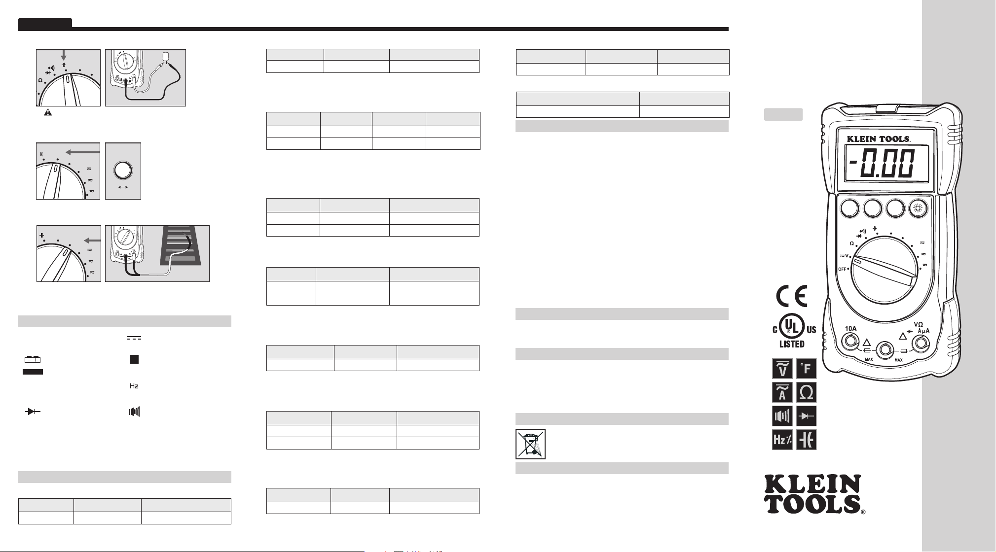
SYMBOLS USED ON LCD
AC Measurement DC Measurement
~
Negative DC Value
-
Low Battery
AUTO
Auto Range Active
Duty Cycle Mode Frequency Mode
%
Current in Amps
A
Diode Test Continuity Test
-9
Nano 10
n
-3
Milli 10
m
µ
k
Micro 10
Kilo 10
-6
3
ELECTRICAL SPECIFICATIONS
DC Voltage Measurement
Range Resolution Accuracy
400mV ~ 600V 0.1mV ~ 1V ± (0.5% + 3 digits)
Overload Protection: 600V RMS Input Impedance: > 10MΩ.
10A/250V
PRESS
H
Hz
10A/250V
H
z%
Temp
µA
mA
A
Temp
m
COM
600V MAX
~
400mA/250V
~
z%
%
H
z%
Temp
µA
mA
A
Temp
m
COM
600V MAX
~
400mA/250V
~
Overload: Range Exceeded
OL
Hold Active
H
Voltage Measurement
V
Resistance in Ohms
Ω
Temperature in Fahrenheit
°
F
Capacitance in Farads
F
Mega 10
M
6
AC Voltage Measurement
Range Resolution Accuracy
4V ~ 600V 1mV ~ 1V ± (1.2% + 5 digits)
Overload Protection: 600V RMS Frequency: 50 ~ 60Hz
Input Impedance: > 10MΩ Response: Averaging
AC/DC Current Measurement
Range Resolution DC Accuracy AC Accuracy
400μA ~ 400mA 0.1μA ~ 0.1mA ± (1.0% + 3 d) ± (1.2% + 3 d)
10A 0.01A ± (3.0% + 5 d) ± (3.0% + 5 d)
Overload Protection:
• mA Input: F400mA / 250V fuse
• 10A Input: F10A / 500V fuse
Max Input Current:
• mA Input: 400mA DC / AC RMS
• 10A Input: 10A DC / AC RMS
Resistance Measurement
Range Resolution Accuracy
400Ω ~ 4MΩ 0.1Ω ~ 0.001MΩ ± (0.8% + 4 digits)
40MΩ 0.01MΩ ± (1.5% + 4 digits)
Overload Protection: 600V RMS
Capacitance Measurement
Range Resolution Accuracy
4nF ~ 40μF 0.001nF ~ 0.01μF ± (3.0% + 6 digits)
200μF 0.1μF ± (4.0% + 6 digits)
Overload Protection: 600V RMS
4nF Range: Stated accuracy with film capacitor or better.
Frequency Measurement
Range Resolution Accuracy
9.999Hz ~ 999.9kHz 0.001Hz ~ 0.1kHz ± (0.5% + 2 digits)
Overload Protection: 600V RMS
Sensitivity: 0.7V RMS at 1MHz
Temperature Measurement
Range Resolution Accuracy
-4°F ~ 32°F 1°F ± (5.0% + 2 digits)
32°F ~ 1832°F 1°F ± (3.0% + 2 digits)
Overload Protection: 600V RMS
Sensor: K-type thermocouple, accuracy not listed
Duty Cycle Measurement
Range Resolution Accuracy
0.1% ~ 99.9% 0.1% ± (2% + 5 digits)
Overload Protection: 600V RMS
Frequency: 0.5Hz ~ 100kHz (pulsewidth > 2μsec)
Diode Test
Overload Protection Test Current Open Circuit Voltage
600V RMS Appx. 0.6mA Appx. < 1.5V DC
Continuity Test
Overload Protection Open Circuit Voltage
600V RMS Appx. 0.44V
WARRANTY
This product is warranted to be free from defects in materials and workmanship
for a period of two years from the date of purchase. During this warranty period,
Klein Tools has the option to repair or replace or refund the purchase price of
any unit which fails to conform to this warranty under normal use and service.
This warranty does not cover damage which occurs in shipment or failure which
results from alteration, tampering, accident, misuse, abuse, neglect, or improper
maintenance. Batteries and damage resulting from failed batteries are not
covered by warranty. A purchase receipt or other proof of original purchase date
will be required before warranty repairs will be rendered.
Any implied warranties, including but not limited to implied warranties of
merchantability and fitness for a particular purpose, are limited to the express
warranty. Klein Tools shall not be liable for loss of use of the instrument or other
incidental or consequential damages, expenses, or economic loss, or for any
claim or claims for such damage, expenses or economic loss.
Some states or countries laws vary, so the above limitations or exclusions may
not apply to you. This warranty gives you specific legal rights, and you may also
have other rights which vary from state to state. If your Klein product requires
repair or for information on how to exercise your rights under the terms of this
warranty, please contact Klein Tools at 1-877-775-5346.
CLEANING
Turn instrument off and disconnect test leads. Clean the instrument by using
a damp cloth. Do not use abrasive cleaners or solvents.
STORAGE
Remove the batteries when instrument is not in use for a prolonged period of
time. Do not expose to high temperatures or humidity. After a period of storage
in extreme conditions exceeding the limits mentioned in the Specifications
section, allow the instrument to return to normal operating conditions before
using it.
DISPOSAL / RECYCLE
Caution: This symbol indicates that equipment and its accessories
shall be subject to a separate collection and correct disposal.
CUSTOMER SERVICE
KLEIN TOOLS, INC.
450 Bond Street
Lincolnshire, IL 60069
1-877-775-5346
www.kleintools.com
139572TRev. 06/10
Instruction
Instruction
Manual
Manual
MM200
ENGLISH
• BACKLIGHT
• KICK STAND
• LEAD
HOLDER
• AUTO
RANGING
• DATA HOLD
• 3-3/4 DIGIT
3999 COUNT
LCD
www.kleintools.com
FUNC.
HOLD
10A/500V
~
COM
H
z%
H
z%
CATIII
600V MAX
400mA/250V
Temp
MM200
µA
m
~
mA
A
Temp
®
F o r P r o f e s s i o n a l s . . . S i n c e 1 8 5 7
Page 2
ENGLISH
H
z%
H
z%
MM200
Instruction Manual
GENERAL SPECIFICATIONS
The Klein Tools MM200 is an auto-ranging multimeter. It measures
AC / DC voltage, AC / DC current, resistance, capacitance, temperature,
and frequency. It can also test diodes and continuity.
• Operating Altitude: 2000 meters
• Relative Humidity: 75% max operating
• Operating Temperature: 0°C / 32°F to 40°C / 104°F < 75% R.H.
• Storage Temperature: -20°C / -4°F to 60°C / 140°F < 80% R.H.
• Accuracy Temperature: 18°C / 64°F to 28°C / 82°F < 75% R.H.
• Temperature Coefficient: 0.1*(specified accuracy) / °C
• Sampling Frequency: 3 samples per second
• Dimensions: 5.91" x 2.76" x 1.97"
• Weight: 8.36 oz.
• Calibration: Accurate for one year
• CAT Rating: CAT III 600V
• Listing: ETL & cETL standard UL 3111-1 listed
• Pollution Degree: 2
• Accuracy: ± (% of reading + # of least significant digits)
WARNINGS
To ensure safe operation and service of the tester, follow these instructions.
Failure to observe these warnings can result in severe injury or death.
• Before each use, verify meter operation by measuring
a known voltage or current.
• Never use the meter on a circuit with voltages that exceed the
category based rating of this meter.
• Do not use the meter during electrical storms, or in wet weather.
• Do not use the meter or test leads if they appear to be damaged.
• Ensure meter leads are fully seated, and keep fingers away from
the metal probe contacts when making measurements.
• Do not open the meter to replace batteries while the probes
are connected.
• Use caution when working with voltages above 60V DC,
or 25V AC RMS. Such voltages pose a shock hazard.
• To avoid false readings that can lead to electrical shock,
replace batteries if a low battery indicator appears.
• Unless measuring voltage or current, shut off and lock out
power before measuring resistance or capacitance.
• Always adhere to local and national safety codes. Use individual
protective equipment to prevent shock and arc blast injury where
hazardous live conductors are exposed.
SYMBOLS
AC Alternating Current Warning or Caution
~
DC Direct Current Dangerous Levels
DC/AC Voltage or Current Double Insulated Class II
Ground AC Source
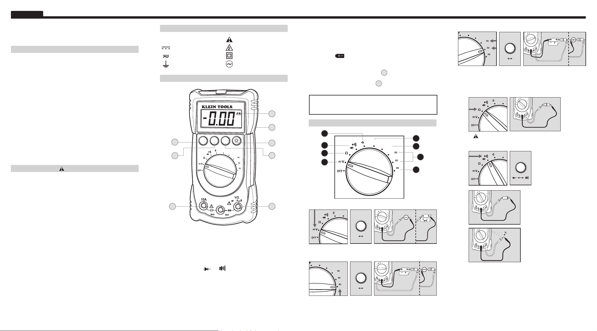
FEATURE DETAILS
MM200
FUNC.
HOLD
H
10A/500V
and .
z%
H
z%
Temp
µA
mA
A
Temp
m
COM
CATIII
600V MAX
~
400mA/250V
~
C
D
B
A. B. Use properly safety-rated leads.
A. Do not attempt to measure more than 600V or 400mA.
B. Do not attempt to measure more than 10A.
C. Select Functionality Button
• Switch between AC and DC.
• Switch between
D. Data Hold
• Press to hold the current input on the display.
• Press again to return to live reading.
E. Select Frequency/Duty Cycle Button
• Switch between measurement, Hz, and %.
H
G
On Back
F
E
A
F. Backlight
• Press to enable/disable lights.
• Using lights drains the battery significantly.
G. H. Battery/Fuse Replacement
• When
indicator is displayed on the LCD, batteries must be
replaced.
• Remove back screw and replace 9V battery.
• If more than 400mA is applied to
fast-blow fuse.
• If more than 10A is applied to
B
, replace with respective
10A/500V fast-blow fuse.
Auto Power-Off
• Device will power off after 15 minutes non-use.
• Turn the dial or press a button to wake.
FUNCTION INSTRUCTIONS
6
H
5
z%
Temp
4
1
1. AC / DC Voltage: < 600V
H
z%
PRESS
FUNC.
AC
DC
• Select AC or DC voltage source.
2. AC / DC Current (large): < 10A
Temp
µA
mA
PRESS
FUNC.
A
AC
DC
• Start with this setting if current level is unknown.
• Attach red lead to “10A” input.
• Select AC or DC current source.
• Current above 10A will require fuse replacement.
H
COM
10A/250V
~
H
z%
COM
10A/250V
~
A
, replace with 400mA/250V
7
8
µA
mA
A
z%
Temp
µA
mA
A
Temp
m
600V MAX
400mA/250V
~
Temp
µA
mA
A
Temp
m
600V MAX
400mA/250V
~
3
2
3. AC/DC Current (small): < 400mA
H
z%
Temp
Temp
mA
PRESS
FUNC.
A
AC
DC
µA
µA
mA
A
Temp
m
COM
600V MAX
10A/250V
~
400mA/250V
~
• Attach red lead to “mAμA” input.
• Select μA or mA, and AC or DC current source.
• Current above 400mA will require fuse replacement.
4. Resistance: < 40M
Ω
H
z%
H
z%
Temp
µA
mA
A
Temp
m
COM
600V MAX
10A/250V
~
400mA/250V
~
• Do not attempt to measure resistance on a live circuit.
5. Diode/Continuity
H
z%
PRESS
FUNC.
H
z%
Temp
µA
mA
A
Temp
m
COM
600V MAX
10A/250V
~
400mA/250V
~
Diode:
Display shows:
• Forward voltage drop if
forward biased.
• “O.L.” if reverse biased.
H
z%
Temp
µA
mA
A
Temp
m
COM
600V MAX
10A/250V
~
400mA/250V
~
Continuity:
• Display shows resistance.
• Buzzer sounds if less than 50
Ω.
Page 3

ESPAÑOL
7. Frecuencia (Hz)/Ciclo de servicio < 1 MHz
µA
µA
mA
A
mA
A
PRESIONE
H
z%
Hz %
H
z%
Temp
µA
mA
A
m
COM
600V MAX
10A/250V
~
400mA/250V
~
OL
H
%
Ω
°
F
F
M
Temp
Sobrecarga: Intervalo excedido
Retener en activo
Modo de ciclo
de servicio
Resistencia en ohmios
Temperatura en Fahrenheit
Capacitancia en faradios
6
Mega 10
H
z%
Temp
• Siga el ajuste de la prueba de tensión de CA.
8. Temperatura: -4° ≤ °F ≤ 1832°
H
z%
Temp
• Utilice el termopar y el adaptador incluidos.
• No aplique tensión al termopar.
SÍMBOLOS UTILIZADOS EN LA PANTALLA DE LCD
Medición de CA Medición de CC
~
Valor de CC negativo
-
Pila baja
Determinación
AUTO
automática del
intervalo activa
Medición de tensión Modo de frecuencia
V
Corriente en A
A
Prueba de diodo Prueba de continuidad
-9
Nano 10
n
-3
Mili 10
m
µ
k
Micro 10
Kilo 10
-6
3
ESPECIFICACIONES ELÉCTRICAS
Medición de tensión de CC
Intervalo Resolución Precisión
400mV ~ 600V 0.1mV ~ 1V ± (0.5% + 3 dígitos)
Protección contra sobrecargas: 600V de valor eficaz (RMS)
Impedancia de entrada: > 10MΩ.
Medición de tensión de CA
Intervalo Resolución Precisión
4V ~ 600V 1mV ~ 1V ± (1.2% + 5 dígitos)
Protección contra sobrecargas: 600V de valor eficaz (RMS)
Frecuencia: 50 ~ 60Hz Impedancia de entrada: > 10MΩ
Respuesta: Promediación
Medición de corriente CA/CC
Intervalo Resolución Precisión de CC Precisión de CA
400μA ~ 400mA 0.1μA ~ 0.1mA ± (1.0% + 3 d) ± (1.2% + 3 d)
10A 0.01A ± (3.0% + 5 d) ± (3.0% + 5 d)
Protección contra sobrecargas:
• mA Input: F400mA / 250V fuse
• Entrada de 10 A: Fusible F10A / 500 V
Corriente de entrada máxima:
• Entrada de mA: 400 mA CC / CA de valor eficaz (RMS)
• Entrada de 10 A: 10 A CC / CA de valor eficaz (RMS)
Medición de resistencia
Intervalo Resolución Precisión
400Ω ~ 4MΩ 0.1Ω ~ 0.001MΩ ± (0.8% + 4 dígitos)
40MΩ 0.01MΩ ± (1.5% + 4 dígitos)
Protección contra sobrecargas: 600V de valor eficaz (RMS)
Mediación de capacitancia
Intervalo Resolución Precisión
4nF ~ 40μF 0.001nF ~ 0.01μF ± (3.0% + 6 dígitos)
200μF 0.1μF ± (4.0% + 6 dígitos)
Protección contra sobrecargas: 600V de valor eficaz (RMS)
Intervalo 4nF: Precisión indicada con capacitor de película o mejor.
Medición de frecuencia
Intervalo Resolución Precisión
9.999Hz ~ 999.9kHz 0.001Hz ~ 0.1kHz ± (0.5% + 2 dígitos)
Protección contra sobrecargas: 600V de valor eficaz (RMS)
Sensibilidad: 0,7 V de valor eficaz (RMS) a 1 MHz
Medición de temperatura
Intervalo Resolución Precisión
-4°F ~ 32°F 1°F ± (5.0% + 2 dígitos)
32°F ~ 1832°F 1°F ± (3.0% + 2 dígitos)
Protección contra sobrecargas: 600V de valor eficaz (RMS)
Sensor: Termopar tipo K, precisión no indicada
Medición del ciclo de servicio
Intervalo Resolución Precisión
0.1% ~ 99.9% 0.1% ± (2% + 5 dígitos)
Protección contra sobrecargas: 600V de valor eficaz (RMS)
Frecuencia: 0,5 Hz ~ 100 kHz (amplitud de pulso > 2 μs)
Prueba de diodo
Protección contra
sobrecargas
Corriente de prueba
Tensión de
circuito abierto
600V (RMS) Aprox. 0.6mA Aprox. < 1.5V DC
Prueba de continuidad
Protección contra sobrecargas Tensión de circuito abierto
600V (RMS) Aprox. 0.44V
GARANTÍA
Se garantiza que este producto estará libre de defectos de materiales y fabricación durante un
período de dos años a partir de la fecha de compra. Durante este período de garantía, Klein
Tools tiene la opción de reparar, reemplazar o reembolsar el precio de compra de cualquier
unidad que no cumpla con esta garantía bajo uso y servicio normales. Esta garantía no cubre
los daños que ocurran en el envío o las fallas que ocurran debido a alteración, manipulación
indebida, accidente, uso incorrecto, abuso, negligencia o mantenimiento inapropiado. Las
pilas y los daños que ocurran por causa de pilas que fallen no están cubiertos por esta
garantía. Se requerirá un recibo de compra u otro comprobante de la fecha de compra original
antes de que se realicen las reparaciones bajo garantía.
Todas las garantías implícitas, incluyendo pero sin estar limitadas a las garantías implícitas
de comerciabilidad e idoneidad para un propósito específico, están limitadas a la garantía
expresa. Klein Tools no será responsable por la pérdida de uso del instrumento u otros daños
incidentales o emergentes, gastos o pérdida económica, ni por cualquier reclamo o reclamos
por dichos daños, gastos o pérdida económica.
Las leyes de algunos estados o países varían, por lo que es posible que las limitaciones o
exclusiones que anteceden no tengan aplicación en el caso de usted. Esta garantía le confiere
a usted derechos legales específicos y es posible que usted tenga también otros derechos
que varían de un estado a otro. Si su producto Klein requiere reparación, o para obtener
información sobre cómo ejercer sus derechos bajo los términos de esta garantía, sírvase
contactar a Klein Tools llamando al 1-877-775-5346.
LIMPIEZA
Apague el instrumento y desconecte los conductores de prueba. Limpie el instrumento
utilizando un paño húmedo. No utilice limpiadores abrasivos ni solventes.
ALMACENAMIENTO
Retire las pilas cuando el instrumento no se vaya a usar durante un período prolongado. No
lo exponga a altas temperaturas o humedad. Después de un período de almacenamiento en
condiciones extremas que excedan los límites mencionados en la sección Especificaciones,
deje que el instrumento regrese a las condiciones de funcionamiento normales antes de
utilizarlo.
ELIMINACIÓN / RECICLAJE
Precaución: Este símbolo indica que el equipo y sus accesorios estarán
sujetos a recogida y desecho correcto por separado.
SERVICIO AL CLIENTE
KLEIN TOOLS, INC.
450 Bond Street
Lincolnshire, IL 60069
1-877-775-5346
www.kleintools.com
139573TRev. 06/10
Manual de
Instrucciones
MM200
ESPAÑOL
• LUZ DE FONDO
• CABALLETE
• DETERMINACIÓN
AUTOMÁTICA DEL
FUNC.
INTERVALO
• PORTACONDUCTORES
DE PRUEBA
• RETENCIÓN DE DATOS
• PANTALLA
DE LCD DE 3999
CONTEOS CON
DÍGITOS DE 3-3/4
www.kleintools.com
HOLD
10A/500V
~
COM
H
z%
H
z%
600V MAX
400mA/250V
CATIII
Temp
MM200
µA
m
~
mA
A
Temp
®
P a r a P r o f e s i o n a l e s . . . D e s d e 1 8 5 7
Page 4

ESPAÑOL
H
z%
H
z%
Temp
MM200
Manual de Instrucciones
ESPECIFICACIONES GENERALES
El MM200 de Klein Tools es un multímetro con determinación automática
del intervalo. Mide tensión de CA / CC, corriente CA / CC, resistencia,
capacitancia, temperatura y frecuencia. También puede probar diodos y
continuidad.
• Altitud de funcionamiento: 2000 metros
•
Humedad relativa: 75% máxima de funcionamiento
•
Temperatura de funcionamiento: 0°C / 32°F a 40°C / 104°F < 75% H.R.
•
Temperatura de almacenamiento: -20°C / -4°F a 60 °C / 140°F < 80% H.R.
•
Temperatura de precisión: 18 °C / 64 °F a 28 °C / 82 °F < 75% H.R.
•
Coeficiente de temperatura: 0.1*(precisión especificada) / °C
•
Frecuencia de muestreo: 3 muestras por segunda
•
Dimensiones: 5,91 x 2,76 x 1,97 pulgadas
•
Peso: 8,36 onzas
•
Calibración: Precisa durante un año
•
Calificación CAT: CAT III 600V
•
Catalogación: Catalogado con el estándar UL 3111-1 ETL y cETL
•
Grado de polución: 2
•
Precisión: ± (% de la lectura + No. de dígitos menos significativos)
ADVERTENCIAS
Para asegurar un funcionamiento y servicio seguros del probador, siga
estas instrucciones. Si no se hace caso de estas advertencias, el resultado
puede ser lesiones graves o muerte.
• Antes de cada uso, verifique el funcionamiento del multímetro midiendo
una tensión o una corriente conocida.
• No utilice nunca el multímetro en un circuito con tensiones que excedan la
capacidad nominal basada en la categoría de este multímetro.
• No utilice el multímetro durante tormentas eléctricas ni en tiempo mojado.
• No utilice el multímetro ni los conductores de prueba si parecen estar
dañados.
• Asegúrese de que los conductores de prueba del multímetro estén
completamente asentados y mantenga los dedos alejados de los contactos
metálicos de los conductores de prueba cuando haga mediciones.
• No abra el multímetro para reemplazar las pilas mientras los conductores
de prueba estén conectados.
• Tenga precaución cuando trabaje con tensiones superiores a 60 V CC, o
25 V CA de valor eficaz (RMS). Dichas tensiones presentan un peligro de
descarga.
• Para evitar lecturas falsas que pueden llevar a descargas eléctricas,
reemplace las pilas si aparece un indicador de pila baja.
• A menos que mida tensión o corriente, apague y bloquee el suministro
eléctrico antes de medir resistencia o capacitancia.
• Cumpla siempre con los códigos de seguridad locales y nacionales. Utilice
equipo de protección individual para evitar las descargas eléctricas y
las lesiones por intensas corrientes de arco donde los conductores con
corriente peligrosos estén al descubierto.
SÍMBOLOS
CA Corriente alterna Advertencia o precaución
~
CC Corriente continua Niveles peligrosos
Tensión o corriente CC/CA
Con aislamiento
doble de Clase II
Conexión a tierra Fuente de CA
DETALLES DE LAS FUNCIONES
MM200
FUNC.
HOLD
H
10A/500V
y .
z%
H
z%
Temp
µA
mA
A
Temp
m
COM
CATIII
600V MAX
~
400mA/250V
~
C
D
B
A. B. Utilice conductores de prueba con capacidad
nominal de seguridad apropiada.
A. No intente medir más de 600 V o 400 mA.
B. No intente medir más de 10 A.
C. Botón de funcionalidad Select
• Cambie entre CA y CC.
• Cambie entre
D. Retención de datos
• Presione para retener la entrada de corriente en la pantalla.
• Presione de nuevo para regresar a la lectura en vivo.
E. Seleccione el botón de frecuencia/ciclo de servicio
• Cambie entre medición, Hz, y %.
F. Luz de fondo
• Presione para activar/desactivar las luces.
• La utilización de las luces descarga significativamente las pilas.
G. H. Reemplazo de las pilas y el fusible
• Cuando el indicador
se muestre en la pantalla de LCD, las
pilas deben ser reemplazadas.
• Retire el tornillo trasero y reemplace las pilas de 9 V.
• Si se aplican más de 400 mA a
A
, reemplace el fusible con un
fusible de fundido rápido de 400 mA/250 V.
• Si se aplican más de 10 A a
B
, reemplace el fusible con el
respectivo fusible de fundido rápido de 10 A/600 V.
Autoapagado
• El dispositivo se apagará después de 15 minutos sin utilizarlo.
H
G
• Gire el dial o presione un botón para activarlo.
FUNCTION INSTRUCTIONS
6
H
F
E
5
4
1
z%
Temp
µA
mA
A
A
1. Tensión de CA / CC: < 600 V
H
z%
PRESIONE
FUNC.
CA
CC
H
z%
Temp
µA
mA
A
Temp
m
COM
600V MAX
10A/250V
~
400mA/250V
~
7
8
3
2
3. Corriente CA/CC (pequeña): < 400 mA
Temp
µA
mA
A
PRESIONE
FUNC.
CA
CC
H
z%
Temp
µA
mA
A
Temp
m
COM
600V MAX
10A/250V
~
400mA/250V
~
• Conecte el conductor de prueba rojo a la entrada de “mAμA”.
• Seleccione μA o mA y la fuente de corriente CA o CC.
• Una corriente por encima de 400 mA requerirá el reemplazo
del fusible.
4. Resistencia: < 40
Ω
H
z%
H
z%
Temp
µA
mA
A
Temp
m
COM
600V MAX
10A/250V
~
400mA/250V
~
• No intente medir resistencia en un circuito con corriente.
5. Diodo/Continuidad
H
z%
PRESIONE
FUNC.
H
z%
Temp
µA
mA
A
Temp
m
COM
600V MAX
10A/250V
~
400mA/250V
~
Diodo:
La pantalla muestra:
• Caída de tensión en sentido
directo si la polarización es directa.
• “O.L.” si la polarización es inversa.
H
z%
Temp
µA
mA
A
Temp
m
COM
600V MAX
10A/250V
~
400mA/250V
~
Continuidad:
• La pantalla muestra resistencia.
• El zumbador suena si es
menos de 50
Ω.
• Seleccione la fuente de tensión de CA o CC.
2. Corriente CA / CC (grande): < 10 A
H
z%
Temp
Temp
mA
A
PRESIONE
FUNC.
CA
CC
µA
µA
mA
A
Temp
m
COM
600V MAX
10A/250V
~
400mA/250V
~
• Comience con este ajuste si el nivel de corriente es desconocido.
• Conecte el conductor de prueba rojo a la entrada de “10A”.
• Seleccione la fuente de corriente CA o CC.
• Una corriente por encima de 10 A requerirá el reemplazo del fusible.
6. Capacitancia < 200 µF
H
z%
H
z%
Temp
µA
mA
A
Temp
m
COM
600V MAX
10A/250V
~
400mA/250V
~
• Descargue el capacitor de manera segura antes de
realizar la medición.
• La lectura puede tomar hasta 60 segundos en el caso de
capacitores grandes.
Page 5

FRANÇAIS
7. Fréquence (Hz) / Cycle de service < 1 MHz
H
z%
Temp
• Suivez la configuration de test de tension c.a.
8. Température : -4° ≤ °F ≤ 1 832°
H
z%
Temp
• Utilisez le thermocouple et l’adaptateur joints.
• N’appliquez pas de tension au thermocouple.
SYMBOLES UTILISÉS SUR L'ÉCRAN ACL
Mesure c.a. Mesure c.c.
~
Valeur c.c. négative Mode de fréquence
-
Décharge partielle
des piles
Plage automatique
AUTO
activée
Mode de cycle
%
de service
Courant en ampères
A
Test de diode Test de continuité
-9
Nano 10
n
-3
Milli 10
m
µ
k
Micro 10
Kilo 10
-6
3
SPÉCIFICATIONS ÉLECTRIQUES
Mesure de la tension c.c.
Plage Résolution Précision
400mV ~ 600V 0.1mV ~ 1V ± (0.5% + 3 chiffres)
Protection contre les surcharges : 600 V eff.
Impédance d'entrée : > 10MΩ.
Mesure de la tension c.a.
Plage Résolution Précision
4V ~ 600V 1mV ~ 1V ± (1.2% + 5 chiffres)
Protection contre les surcharges : 600 V eff. Fréquence: 50 ~ 60Hz
Impédance d'entrée : > 10MΩ Réponse : Péréquation
APPUYEZ
µA
mA
µA
mA
A
A
H
z%
Hz %
H
z%
COM
10A/250V
~
Temp
µA
mA
A
Temp
m
600V MAX
400mA/250V
~
Maintien en
H
position activée
Mesure de la tension
V
Surcharge : Limite
OL
de plage dépassée
Résistance en Ohms
Ω
Température en Fahrenheit
°
F
Capacité en Farads
F
M
Méga 10
6
Mesure du courant c.a./c.c.
Plage Résolution Précision c.c. Précision c.a.
400μA ~ 400mA 0.1μA ~ 0.1mA ± (1.0% + 3 c) ± (1.2% + 3 c)
10A 0.01A ± (3.0% + 5 c) ± (3.0% + 5 c)
Protection contre les surcharges :
• Entrée mA : Fusible rapide F 400 mA / 250 V
• Entrée 10 A : F 10 A / fusible 500 V
Courant d’entrée max. :
• Entrée mA : 400 mA c.c. / c.a. eff.
• Entrée 10 A : 10 A c.c. / c.a. eff.
Mesure de la résistance
Plage Résolution Précision
400Ω ~ 4MΩ 0.1Ω ~ 0.001MΩ ± (0.8% + 4 chiffres)
40MΩ 0.01MΩ ± (1.5% + 4 chiffres)
Protection contre les surcharges : 600 V eff.
Mesure de la capacité
Plage Résolution Précision
4nF ~ 40μF 0.001nF ~ 0.01μF ± (3.0% + 6 chiffres)
200μF 0.1μF ± (4.0% + 6 chiffres)
Protection contre les surcharges : 600 V eff.
Plage 4nF : Précision indiquée avec condensateur à film ou mieux.
Mesure de la fréquence
Plage Résolution Précision
9.999Hz ~ 999.9kHz 0.001Hz ~ 0.1kHz ± (0.5% + 2 chiffres)
Protection contre les surcharges : 600 V eff.
Sensibilité : 0,7 V eff. à 1 MHz
Mesure de la température
Plage Résolution Précision
-4°F ~ 32°F 1°F ± (5.0% + 2 chiffres)
32°F ~ 1832°F 1°F ± (3.0% + 2 chiffres)
Protection contre les surcharges : 600 V eff.
Capteur : thermocouple de type K, précision non indiquée
Mesure du cycle de service
Plage Résolution Précision
0.1% ~ 99.9% 0.1% ± (2% + 5 chiffres)
Protection contre les surcharges : 600 V eff.
Fréquence : 0,5Hz ~ 100 kHz (largeur d’impulsion > 2 μsec)
Test de diode
Protection contre les
surcharges
Courant de test
Tension de circuit
ouvert
600V eff. Appx. 0.6mA Appx. < 1.5V c.c.
Test de continuité
Protection contre les surcharges Tension de circuit ouvert
600V eff. Appx. 0.44V
GARANTIE
Ce produit est garanti sans défauts de matériau ou de fabrication pendant une période de
deux ans à compter de la date de l’achat. Pendant cette période de garantie, à son choix,
Klein réparera ou remplacera tout produit qui ne serait pas conforme à cette garantie dans
des conditions normales d’utilisation et de service, ou en remboursera le prix d’achat. Cette
garantie ne couvre pas les dommages qui surviennent pendant l’expédition ou les défaillances
qui résultent d’une altération, d’une falsification, d’un accident, d’une utilisation non conforme
ou abusive, de négligence ou d’une maintenance incorrecte. Les piles et les dommages
résultant de piles défectueuses ne sont pas couverts par la garantie. Un reçu d’achat ou un
autre justificatif indiquant la date de l’achat initial sera exigé avant que des réparations ne
soient effectuées dans le cadre de la garantie.
Toutes garanties implicites, y compris, entre autres, les garanties implicites de qualité
marchande et d’adéquation à un but particulier, sont limitées à la garantie expresse. Klein
Tools n’assumera aucune responsabilité au titre de la perte d’utilisation de l’instrument ou
pour d’autres dommages, frais ou pertes économiques secondaires ou accessoires, ou en cas
de réclamation ou de réclamations pour de tels dommages, frais ou pertes économiques.
Étant donné que les lois de certains États, de certaines provinces ou de certains pays varient,
les limitations ou exclusions ci-dessus ne s’appliquent peut-être pas à vous. Cette garantie
vous confère des droits particuliers, et vous pouvez aussi avoir d’autres droits qui varient
selon l’État ou la province où vous résidez. Si votre produit Klein nécessite des réparations ou
pour connaître la façon de faire valoir vos droits en vertu des termes de la présente garantie,
veuillez contacter Klein Tools au 1-877-775-5346.
NETTOYAGE
Éteignez l'instrument et déconnectez les fils de test. Nettoyez l'instrument en utilisant un tissu
humide. N’utilisez pas de solvants ou de produits de nettoyage abrasifs.
RANGEMENT
Retirez les piles lorsque l'instrument ne va pas être utilisé pendant une période prolongée.
N'exposez pas à une température ou une humidité élevée. À la suite d'une période de
rangement dans des conditions extrêmes dépassant les limites mentionnées dans la section
consacrée aux spécifications, laissez l'instrument retourner dans des conditions de mesure
normales avant de vous en servir à nouveau.
MISE AU REBUT/RECYCLAGE
Mise en garde: Ce symbole indique que l'équipement et ses accessoires
doivent faire l'objet d'une élimination distincte et d'une mise au rebut
conforme aux règlements.
SERVICE À LA CLIENTÈLE
KLEIN TOOLS, INC.
450 Bond Street
Lincolnshire, IL 60069
1-877-775-5346
www.kleintools.com
139574TRev. 06/10
Mode
d'Emploi
MM200
FRANÇAIS
• BÉQUILLE
D’APPUI
• ÉTRIER
• RÉTENTION
DES DONNÉES
• RÉTROÉCLAIRAGE
• SÉLECTION
AUTOMATIQUE
DE GAMME
• LCD 3 999
POINTS
3 3/4 CHIFFRES
www.kleintools.com
FUNC.
HOLD
10A/500V
~
COM
H
z%
H
z%
CATIII
600V MAX
400mA/250V
Temp
MM200
µA
m
~
mA
A
Temp
®
Pour les Professionnels...Depuis 1857
Page 6

FRANÇAIS
H
z%
H
z%
H
z%
Temp
Temp
MM200
Mode d’Emploi
SPÉCIFICATIONS GÉNÉRALES
L’appareil Klein Tools MM200 est un multimètre à sélection automatique de
gamme. Il mesure la tension c.a./c.c., le courant c.a./c.c., la résistance, la
capacité, la température et la fréquence. Il peut également tester des diodes
et la continuité.
• Altitude de service : 2 000 mètres
• Humidité relative : 75% max. en service
• Température de service : 0° C / 32° F à 40° C / 104° F < 75 % H.R.
• Température de stockage : -20° C / -4° F à 60° C / 140° F < 80 % H.R.
• Précision en température : 18° C / 64° F à 28° C / 82° F < 75 % H.R.
• Coefficient de température : 0,1 * (précision spécifiée) / °C
• Fréquence d’échantillonnage : 3 échantillons par seconde
• Dimensions : 5,91 po x 2,76 po x 1,97 po
• Poids : 8,36 oz.
• Étalonnage : Précis pendant un an
• Qualification de cat. : CAT III 600V
• Homologation : Homologation ETL & cETL standard UL 3111-1
• Degré de pollution : 2
• Précision : ± (% de lecture + nombre de chiffres les moins significatifs)
AVERTISSEMENTS
Pour assurer un fonctionnement et un service sans danger du testeur,
suivez les instructions ci-après. Le non-respect des ces avertissements
risquerait de causer des blessures graves ou même la mort.
• Avant chaque emploi, vérifiez le fonctionnement de l’appareil en mesurant une
tension ou un courant connu.
• N’utilisez jamais cet appareil de mesure sur un circuit dont la tension dépasse la
valeur nominale indiquée pour la catégorie sur cet appareil.
• N’utilisez pas cet appareil de mesure pendant un orage électrique ou par temps
humide.
• N’utilisez pas cet appareil de mesure ou les fils d’essai s’ils semblent être
endommagés.
• Assurez-vous que les fils de connexion de l’appareil de mesure sont bien à leur
place, et gardez les doigts à distance des contacts de la sonde en métal lorsque
vous effectuez des mesures.
• N’ouvrez pas l’appareil de mesure pour remplacer des piles pendant que les
sondes sont toujours connectées.
• Prenez des précautions lorsque vous travaillez avec des tensions de plus de
60 V c.c. ou de 25 V c.a. eff. De telles tensions présentent un risque de choc
électrique.
• Pour éviter des lectures erronées qui pourraient causer un choc électrique,
remplacez les piles si un voyant indiquant que les piles sont déchargées
s’allume.
• Sauf si vous êtes en train de mesurer une tension ou un courant, mettez
l’appareil hors circuit et verrouillez-le avant de mesurer une résistance ou une
capacité.
• Respectez toujours les dispositions des codes de sécurité national et local.
Utilisez des équipements de protection individuelle pour éviter tout risque de
choc électrique ou de blessure causée par une explosion électrique lorsque des
conducteurs sous tension dangereux sont exposés.
SYMBOLES
Courant alternatif c.a.
~
Courant continu c.c. Niveaux dangereux
Tension ou courant c.c./c.a. Classe II, double isolation
Masse Source c.a.
Avertissement ou Mise en
garde
DÉTAILS DES FONCTIONS
MM200
H
G
FUNC.
HOLD
H
10A/500V
COM
~
et .
z%
H
z%
600V MAX
400mA/250V
CATIII
Temp
F
µA
mA
A
Temp
m
E
A
~
C
D
B
A. B. Utilisez des conducteurs de sécurité appropriés.
A. Ne tentez pas d’effectuer une mesure d’une tension supérieure
à 600 V ou d’un courant supérieur à 400 mA.
B. Ne tentez pas d’effectuer une mesure d’un courant d’intensité
supérieure à 10 A.
C. Bouton de sélection de fonctionnalité
• Commutation entre c.a. et c.c.
• Commutation entre
D. Rétention des données
• Appuyez pour maintenir la valeur actuelle sur l’écran.
• Appuyez à nouveau pour retourner à la valeur actuelle.
E. Sélectionnez le bouton de fréquence/cycle de service
• Commutation entre mesure, Hz et %.
F. Rétroéclairage
• Appuyez pour activer/désactiver les lumières.
• L’utilisation des lumières décharge rapidement les piles.
G. H. Remplacement des piles / du fusible
• Lorsque le voyant
est affiché sur l’écran ACL, ll faut
remplacer les piles.
• Retirez la vis arrière et remplacez les piles de 9 V.
• Si un courant d’une intensité de plus de 400 mA est appliqué à
, remplacez avec un fusible à fusion rapide de 400 mA/250 V.
A
• Si un courant d’une intensité de plus de 10 A est appliqué à
remplacez avec un fusible à fusion rapide de 10 A/600 V.
Mise hors tension automatiquement
• L’appareil se mettra hors tension au bout de 15 minutes
d’inutilisation.
• Tournez le cadran ou appuyez sur un bouton pour réactiver
l’appareil.
FUNCTION INSTRUCTIONS
6
H
FUNC.
FUNC.
z%
10A/250V
10A/250V
Temp
H
z%
COM
~
H
z%
COM
600V MAX
~
400mA/250V
µA
mA
A
Temp
µA
mA
A
Temp
m
600V MAX
400mA/250V
~
Temp
µA
mA
A
Temp
m
~
5
4
1
1. Tension c.a./c.c. : < 600 V
H
z%
APPUYEZ
c.a. c.c.
• Sélectionnez la source de tension c.a. ou c.c.
2. Courant c.a. / c.c. (fort) : < 10A
Temp
µA
• Commencez par ce paramètre si le niveau actuel est inconnu.
• Connectez le fil rouge à l’entrée « 10A ».
• Sélectionnez la source de courant c.a. ou c.c.
• Si le courant a une intensité de plus de 10 A, il faudra remplacer
le fusible.
mA
A
APPUYEZ
c.a. c.c.
3. Courant c.a./c.c. (faible) : < 400mA
Temp
µA
B
,
mA
A
APPUYEZ
FUNC.
c.a. c.c.
H
z%
Temp
µA
mA
A
Temp
m
COM
600V MAX
10A/250V
~
400mA/250V
~
• Connectez le fil rouge à l’entrée « mAμA ».
• Sélectionnez la source de courant μA ou mA, et c.a. ou c.c.
• Si le courant a une intensité de plus de 400 mA, il faudra
remplacer le fusible.
4. Résistance : < 40MΩ
H
z%
7
8
• Ne tentez pas de mesurer la résistance sur un
circuit sous tension.
H
z%
Temp
µA
mA
A
Temp
m
COM
600V MAX
10A/250V
~
400mA/250V
~
5. Diode/Continuité
3
2
H
z%
COM
600V MAX
10A/250V
~
400mA/250V
H
z%
APPUYEZ
FUNC.
Temp
µA
mA
A
Temp
m
~
Diode :
L'écran affiche :
• Chute de tension directe en cas
de polarisation en sens direct.
• « O.L. » en cas de polarisation
µA
mA
A
Temp
m
COM
600V MAX
10A/250V
~
400mA/250V
~
6. Capacité < 200 µF
H
z%
dans le sens inverse.
Continuité :
• L'écran affiche la résistance.
• L’avertisseur sonore retentit
si la valeur est inférieure à 50
H
z%
Temp
µA
mA
A
Temp
m
COM
600V MAX
10A/250V
~
400mA/250V
~
Ω.
• Déchargez la capacité en prenant les précautions nécessaires
avant de faire la mesure.
• L’affichage de la lecture peut prendre jusqu’à 60 secondes
dans le cas des grands condensateurs.
 Loading...