


VDV ScoutTM Pro 3
ENGLISH pg. 2
INSTRUCTION MANUAL
• VOICE, DATA AND VIDEO CABLE TESTING
• DETECTS SHORT FAULTS, OPEN FAULTS,
REVERSALS, MISWIRES, CROSSOVER WIRING
AND SPLIT PAIRS
• POWER OVER ETHERNET (PoE)
• CABLE ID
• LENGTH MEASUREMENT
• TONE GENERATOR
• EXTRA-LARGE BACKLIT LCD
• HUB BLINK
• AUTO POWER-OFF
DEUTSCH pg. 12
GEBRAUCHSANLEITUNG
• PRÜFUNG VON KABELN FÜR SPRACH-, DATEN- UND
VIDEOÜBERTRAGUNG
• ERKENNT KURZSCHLÜSSE, UNTERBRECHUNGEN,
VERPOLUNG, VERDRAHTUNGSFEHLER UND SPLIT PAIRS
• POWER OVER ETHERNET (PoE)
• KABEL-ID
• LÄNGENMESSUNG
• TONGENERATOR
• EXTRA GROSSES BELEUCHTETES LCD-DISPLAY
• HUB-BLINK-FUNKTION
• AUTOMATISCHE ABSCHALTUNG
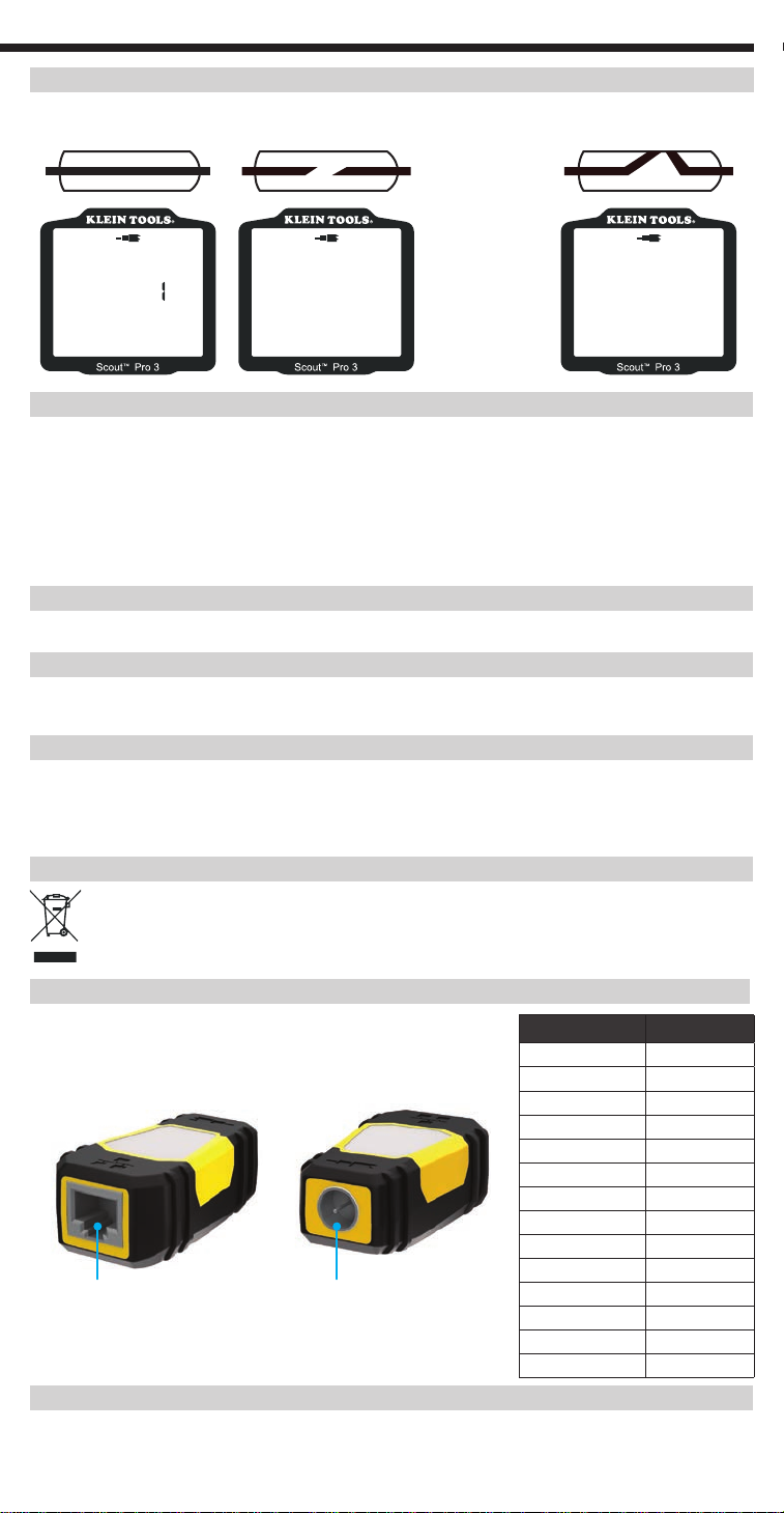
Pass X-over Rev
Fail Short
Split Open
m
ft
1 234
VDV501-852
VDV501-853
Shielded
A
+
B
PoE
ID
5 6
7
8
FRANÇAIS pg. 22
MODE D’EMPLOI
• TEST DE CÂBLES TÉLÉPHONIQUES, DE DONNÉES ET VIDÉO
• DÉTECTE LES COURT-CIRCUITS, LES CIRCUITS OUVERTS,
LES INVERSIONS, LES ERREURS DE CÂBLAGE, LES CÂBLES
CROISÉS ET LES PAIRES DIVISÉES
• POWER OVER ETHERNET (PoE)
• IDENTIFICATION DE CÂBLE
• MESURE DE LONGUEUR
• GÉNÉRATEUR DE TONALITÉ
• TRÈS GRAND ÉCRAN LCD RÉTROÉCLAIRÉ
• CLIGNOTEMENT DE CONCENTRATEUR (HUB BLINK)
• MISE HORS TENSION AUTOMATIQUEV
ESPAÑOL pg. 32
MANUAL DE INSTRUCCIONES
• COMPROBACIÓN DE CABLES DE VOZ, DATOS Y VÍDEO
• DETECTA CORTOS, ABERTURAS, INVERSIONES, CONEXIONES
INCORRECTAS, CABLEADOS CRUZADOS Y PARES DIVIDIDOS
• ALIMENTACIÓN A TRAVÉS DE ETHERNET (Power over Ethernet, PoE)
• IDENTIFICACIÓN DE CABLES
• MEDICIÓN DE LONGITUD
• GENERADOR DE TONOS
• PANTALLA LCD RETROILUMINADA EXTRAGRANDE
• PARPADEO EN EL HUB
• APAGADO AUTOMÁTICO
ENGLISH
GENERAL SPECIFICATIONS
The Klein Tools VDV ScoutTM Pro 3 is a portable voice-data-video cable tester. It tests and
troubleshoots RJ11, RJ12, RJ45 and F-connector terminated cables, and provides tone generation
for cable tracing. The VDV ScoutTM Pro 3 also measures cable length, tests for shield, performs hub
blink testing and traces up to 19 locations (up to 5 locations with the included remotes, additional
remotes are available separately).
Dimensions: 6.5" x 3.0" x 1.6" (16.5 x 7.6 x 4.1 cm)
•
11 oz. (312 g) with battery and remote
Weight:
•
Operating Temperature: 32° to 122 °F (0° to 50 °C)
•
Storage Temperature: -4° to 140 °F (-20° to 60 °C)
•
Humidity: 10% to 90%, non-condensing
•
Maximum Voltage (between any two connector
•
pins without damage):
- RJ Jack: 66V DC or 55V AC
- F-Connector: 66V DC or 55V AC
To ensure the safe operation and service of the tester, please follow these instructions. Failure to
observe these warnings can result in severe injury or death.
The PoE jack, located on the right side of the ScoutTM Pro 3 is the only jack designed for PoE energised
•
cables. Connecting AC energised cables to any port may damage it and pose a safety hazard to the user.
Improperly terminated RJ plugs have the potential to damage the jacks on the VDV Scout
•
inspect an RJ plug before inserting it into the tester. The contacts should always be recessed into the plastic
housing of the plug. Plugging 6-position plugs into the 8-position jack on the tester has the potential to
damage the outer-most contacts of the jack, unless the plug is specifically designed for that purpose.
SYMBOLS ON THE TESTER
Warning or Caution Do NOT use on energised circuits.
Battery Life (9V alkaline):
•
- Standby: 4 years
- Active: 50 hours (without backlight)
Cable Types: Shielded or unshielded; Cat7a, Cat7,
•
Cat6a, Cat6, Cat5e, Cat3, Coaxial
Length Measurement Method: Capacitance
•
Length Measurement Range:
•
1.5' to 1999' (0.5 m to 610 m) with 15 pF/ft
Length Accuracy:
•
Length Constant Range:
•
(5% ft) or (5% m)
10 pF/ft to 40 pF/ft (33 pF/m to 132 pF/m)
WARNINGS
TM
Pro 3. Visually
Always wear approved eye protection. Read the instructions
Conformité Européenne. Conforms with European Economic Area directives.
This symbol indicates that the equipment and its accessories shall be subject to separate
collection and correct disposal.
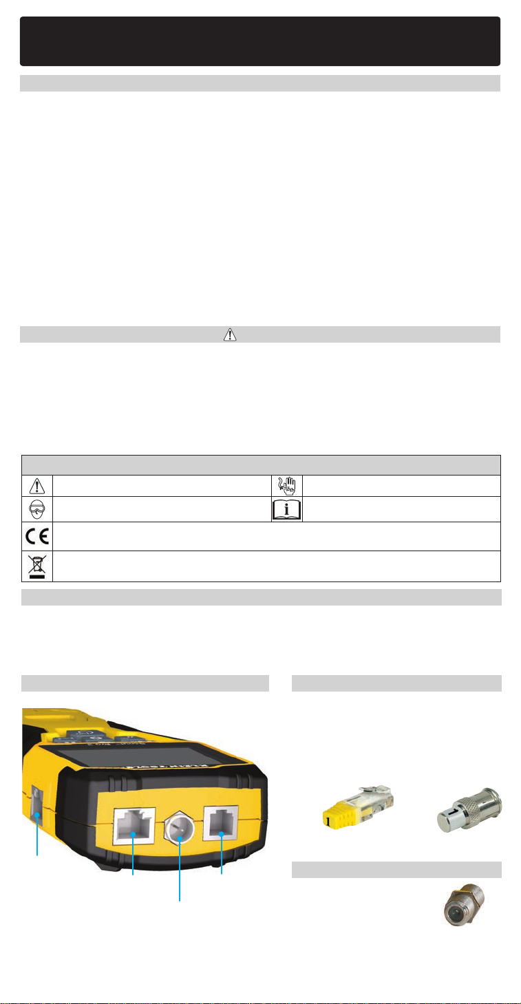
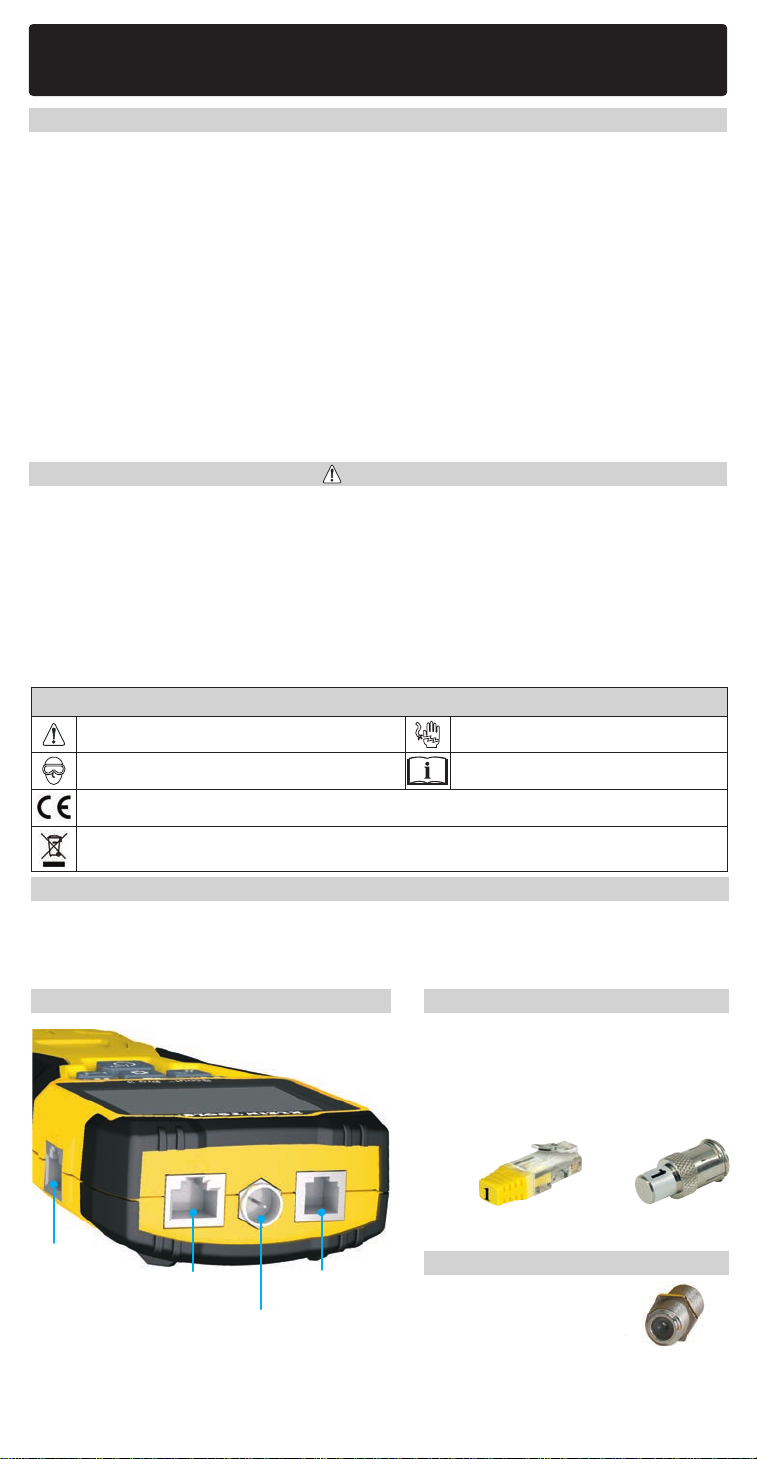
PORTS AND REMOTES OVERVIEW
RJ45 Port: Data cable, Ethernet cable, Cat5e, Cat6, Cat6a, Cat7, Cat7a.
F-Connector Port: Video cable, coaxial cable, RG6/RG6Q cable, RG59 cable.
RJ11/12 Port: Voice cable, POTS (plain old televoice service) cable, 4-wire cable, 6-wire cable,
2 twisted-pair cables, 3 twisted-pair cables, Cat3.
VDV SCOUTTM PRO 3 TESTER LOCATION ID REMOTES
Use for cable location identification mapping.
Set Nos. 1–5 included with VDV500-851,
setNos. 1–18 included with VDV501-852 and
sold separately.
LanMap™
Location ID Remote**
VDV526-055
RJ45
CoaxMap™
Location ID Remote**
VDV512-056
F-connector
connector
**Cannot be used to perform wire map or
cable length tests.
PoE port*
RJ11/12 port*RJ45 port*
F-connector port
Barrel Connector
VDV814-609
Female-to-female F-connector
CONNECTORS
Use with F-connector port
*The RJ jacks share internal connections, so only one RJ cable can be connected at a time for accurate cable
test results. However, an RJ cable and a coax cable may be connected at the same time. In ID mode, all
connectors on the VDV Scout
2
TM
Pro 3 may be connected at the same time.
ENGLISH
port
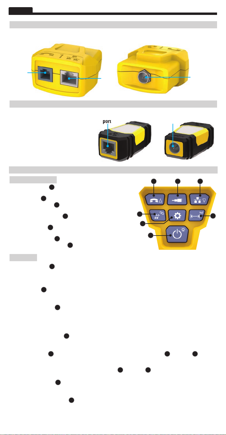
SELF-STORING TEST + MAP™ ID REMOTE (VDV501-210)
Use for cable location identification mapping and/or continuity testing. Self-storing remotes display
on tester as Remote ID No. 1. Included with all VDV ScoutTM Pro 3 models.
RJ11/12
port
RJ45
port
F-connector
port
TEST + MAP™ ID REMOTES (VDV501-2## SERIES)
Use for cable location identification
mapping and continuity testing.
Remotes display on tester asRemote ID
RJ45
port
F-connector
port
Nos. 1-12. Set Nos. 2–6 included with
VDV500-853 and sold separately, set
Nos. 7–12 sold separately, individual
remote Nos. 1–12 each sold separately.
KEYPAD FUNCTION
QUICK REFERENCE
A
B C
• VOICE / UP BUTTONA: Performs wiremap test on RJ11/RJ12
terminated cable, toggles selection upward in other modes.
B
• VIDEO BUTTON
• DATA / DOWN BUTTON
terminated cable, toggles selection downward in other modes.
• TONE / HUB BLINK BUTTON
tone cadences, initiates Hub Blink.
• SETTINGS BUTTON
enters Length Constant Edit mode.
• LENGTH / PoE BUTTON
• POWER / BACKLIGHT BUTTON
: Performs continuity test on F-terminated coax cable.
C
: Performs wiremap test on RJ45
D
: Cycles through available
E
: Selects feet or metres,
F
: Measures cable length, initiates PoE test.
G
: Turns unit on or off, turns backlight on or off.
D
E
F
G
IN DETAIL
• VOICE / UP BUTTONA: Short Press: Initiates wiremap test on RJ11/RJ12 terminated cable. When in Tone or
Length Test mode, the first short press selects Voice mode, while repeated short presses selects wires orpairs of
wires. Long press: Turns Loop mode on or off. When in Tone or Length Test mode, returns to the home screen.
When in Settings mode, changes UOM from feet to metres, or increases the length contant value.
• VIDEO BUTTONB: Short Press: Initiates continuity test on an F-terminated coax cable.
Test mode, a short press selects Video mode.
Long Press:
Turns Loop mode on or off. When in Tone or Length
When in Tone or Length
Test mode, returns to the home screen.
• DATA / DOWN BUTTONC:
Short Press: Initiates wiremap test on RJ45 terminated cable. When in Tone or Length Test mode, first short press
selects Data mode, while repeated short presses select wires or pairs of wires. Long Press: Turns Loop mode on or
off. When in Tone or Length Test mode, returns to the home screen. When in Settings mode, changes UOM from
feet to metres, or increases the length contant value.
• TONE / HUB BLINK BUTTOND: Short Press: Repeated short presses will toggle through the available tone
cadences. Long Press: Initiates Hub Blink.
NOTE: DO NOT attempt to use Hub Blink function when connected to a
Power over Ethernet (PoE) active port.
• SETTINGS BUTTONE: Short Press: Enters Length Constant edit mode (use the UP A and DOWN C buttons
to adjust the value). Default for Length Constant mode is the wire pair of Pins 1 and 2 of data/RJ45 cable, and
the wire pair of Pins 3 and 4 of voice/phone cable. See the LENGTH CONSTANT section for more details. Second
Short Press: Displays option of feet or metres (use the UP A and DOWN C buttons to change). See the
LENGTH MEASUREMENT section for details. Long Press: Exits Settings mode and returns to the home screen.
• LENGTH / PoE BUTTONF: Short Press: Initiates cable length test. Test will default to a cable connected to the
RJ45 port. By default, the test will initiate on the first wire with no faults found. See the LENGTH MEASUREMENT
and LENGTH CONSTANT sections for more details.
Long Press: Initiates PoE test.
• POWER / BACKLIGHT BUTTONG: Short Press: First short press turns the unit on, repeated short presses will
turn thebacklight on and off. Press the power button a second time to turn the LCD backlight on or off.
Long Press: Turns unit off.
NOTE: Unit will automatically power off after 5 minutes of inactivity, or after
60minutes when in Tone mode.
3
ENGLISH
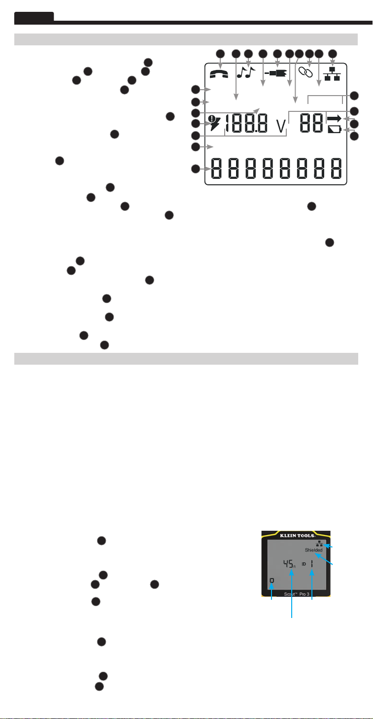
DISPLAY
3 4 511011 13
• MODE: The top line of the display shows what cable
type is being tested; voice (RJ11/RJ12) 1, video
(F-terminated coax) 3 or data (RJ45) 5, and if
HubBlink mode 4 or Tone mode 2 is activated.
• PASS/SPECIAL CABLES: 'Pass' 6 will be displayed
if the cable is a properly wired 4-pair T568A/B data
cable, a 3-pair one-to-one wired voice cable or a
video cable with no faults. In addition, 'X-over'
illuminates if a properly wired cross-over (uplink)
cable is recognised, or 'Rev' 8 illuminates if the
cable is a properly wired reverse-pinned voice cable.
The wire map will show actual pin connections.
'Shielded' 9 illuminates when a shielded data cable
is properly connected at both ends. It will be flashing
if there is a short to a wire in the cable along with that
pin number and the 'Short' 11 indicator.
• CABLE FAULTS: 'Fail' 10 will illuminate only if the cable is not wired to one of the cabling standards. 'Short' (two
wires making conductive contact)
not making connection at both ends of the cable) 13, or a combination of these will also illuminate to indicate the
type of fault(s) detected. SeeWIRING AND DISPLAY EXAMPLES section for wire standards and failure modes.
• VOLTAGE CHECK: A check for voltage on the RJ45 terminated data cable is performed before each test, and if
found, no test is run. If a voltage is detected on any of the tester connectors, the lightning bolt icon
illuminates. The tester should be disconnected immediately from the source of the voltage.
• MEASUREMENT:15 Length mode: Length of cable run in feet or metres. PoE mode: Voltage.
• LOCATION ID:16The remote ID number will display here.
• BATTERY STATUS: The battery low icon 17 illuminates when the battery is nearing depletion. The icon will
illuminate when the battery needs to be replaced. Results may be unreliable at this point.
• TESTER-END WIRE MAP:18 Displays the pins on the tester end of the cable in order. These pins are mapped
to the pins on the remote-end shown directly below them on the LCD
• REMOTE-END WIRE MAP:19Displays the corresponding pin on the remote-end. Dashed lines on this row
indicate shorted pins. No pin numbers displayed on this row line are open pairs.
• PoE INDICATORS:20Indicate PoE configuration. See the chart on page 10 for details.
• PoE ERROR INDICATOR:21Indicates no PoE detected when the test is initiated.
LENGTH MEASUREMENT: The VDV ScoutTM Pro 3 uses the capacitive properties of a cable to measure its
length. One end of the cable should be connected to the corresponding port on the top of the tester. The other
end should be left disconnected or attached to the self-storing remote.
LENGTH CONSTANT:
its length. Every cable has an associated length constant in units of picofarads per foot (pF/ft). Setting the length
constant on the tester is important for obtaining an accurate cable length measurement from the VDV Scout
3. The default length constants are as follows: Voice: 17.0 pF/ft Data: 15.0 pF/ft Video: 15.0 pF/ft
The length constant can sometimes be provided by the manufacturer of the cable (see DISPLAYING/EDITING LENGTH
CONSTANT section). You may have to determine the length constant yourself (see DETERMINING AN UNKNOWN
LENGTH CONSTANT section). Length constants can range from 10 pF/ft to 40 pF/ft.
Measurement accuracy is dependent on how close the tester can be set to the length constant of the cable being
measured and the consistency of the cable along its length.
The length constant can vary from cable to cable, even if it is of the same type, produced by the same manufacturer. It
can also vary over the length of one cable, because the length constant is dependent on the physical properties of the
cable, which may not be consistent throughout the entire cable. The change in wire-pair spacing through the cable can
vary the length constant along the length of the cable.
When setting the length constant using a length of cable, the cable should be at least 50' (15.2 m) long. This will yield
a ±5% uncertainty (1 in 50) in the length constant accuracy. A longer cable reduces this uncertainty.
MEASURING LENGTH – VOICE OR DATA CABLES:
1. Press the Power button
2. Connect one end of the cable to the appropriate port: RJ45 port
(if testing data cable) or RJ12 port (if testing voice cable), located at the top
of the main tester body. Leave the other end of the cable unterminated.
3. Press the Length buttonF to enter Length mode.
4. Press the Data button C or Voice button A,
depending on the cable being tested, to begin the test.
5. Press the Data buttonC repeatedly to select the pair of wires that
should be measured. The first functional pair is chosen by default.
6. Read the length measurement as shown
MEASURING LENGTH – COAX CABLES:
1. Press the Power button
2. Connect one end of the cable to the F-connector port
located at the top of the main tester body.
Leave the other end of the cable unterminated.
3. Press the Length buttonF to enter Length mode.
4. Press the Video buttonBto begin the test.
5. Read the length measurement as shown
4
The length constant refers to the electrical characteristic of a cable used to characterise
11
, 'Split' (wire pairs not maintained as pairs when terminated) 12, 'Open' (wires
OPERATING INSTRUCTIONS
G
to turn the tester on.
.
G
to turn the tester on.
.
6
Pass X-over Rev
Fail Short
12
7
14
15
18
1 2
19
NOTE: A voice or data cable under test can be
unterminated (open) or terminated by an RJ45
ID remote. If it is terminated by the self-storing
remote, the reading will be 1' or 2' greater
than the actual measurement. In this case,
subtract 1' or 2' from the reading to obtain the
actual measurement. The coax cable under test
may be left unterminated.
7 8 92
Shielded
Split Open
m
ft
3
4
Test Running
Continuously
Measured Length = 45 ft.
PoE
ID
5 6
Remote ID No.
(if terminated)
7
A
+
B
8
14
TM
Pro
Cable
Type
Indicates
Shielded
cable
20
16
21
17
OPERATING INSTRUCTIONS
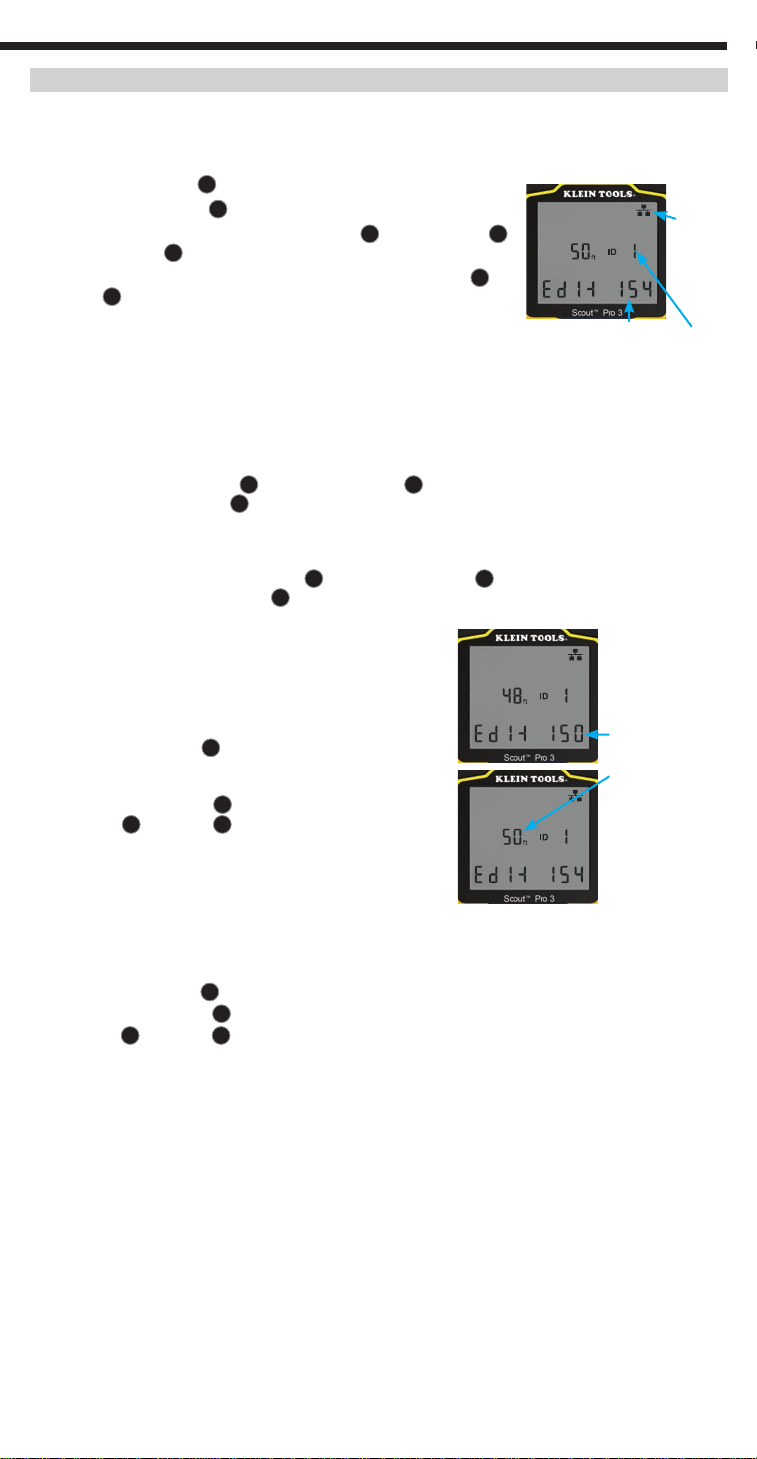
DISPLAYING/EDITING LENGTH CONSTANT:
Follow these instructions to set the length constant based on a known value (for example, as given by the cable
manufacturer). The VDV Scout
data and video).
TM
Pro 3 stores a separate length constant for each of the three cable types (voice,
1. Press the Power buttonG to turn the tester on.
2.
Press the Settings button
3.
Select the cable type by pressing the Voice button
E
.
A
, the Coax button
B
Cable
Type
or the Data buttonC.
The length constant will be displayed with the word 'EDIT'. Use the UP
A
and DOWNC buttons to increase or decrease the Length Constant value
in units of 0.1 pF/ft to the desired value. The decimal is not displayed, so for
example, '154' on the display means that the Length Constant is 15.4 pF/ft.
Length Constants are displayed in pF/ft or pF/m, depending on the selected
154 = 15.4 pF/ft
Remote ID No.
(if terminated)
unit of measurement mode.
NOTE: The Length Constant can only be edited in the pF/ft mode. It is not editable in the pF/m mode.
NOTE: The Default for Length Constant edit for the Data cable is the wire pair of Pins 1 and 2. If you wish to set
the Cable Length constant on wire pairs other than Pins 1 and 2 of a data/RJ45 cable, follow Steps 1 through
F
3 above. Press the Length button
displayed. Press the Edit button
. Press the Data buttonC repeatedly until the pair you wish to edit is
E
again, and you will be editing the wire pair you just selected.
NOTE: The Default for Length Constant edit for the Voice cable is the wire pair of Pins 3 and 4 of a voice cable.
If you wish to set the Cable Length constant on Wire pairs other than pins 3 and 4 of a voice cable, follow Steps
F
1 through 3 above. Press the Length button
edit is displayed. Press the Edit button
. Press the Voice buttonA repeatedly until the pair you wish to
E
again, and you will be editing the wire pair you just selected.
DETERMINING AN UNKNOWN LENGTH CONSTANT:
Follow these instructions to set the Length Constant based on a
sample cable of known length. For the best accuracy, the sample
cable should be 50 ft or longer. This example will use 50 ft.
1. Acquire a known length of cable at least 50 ft in length (50 ft in
this example) of the same type that you would like to measure.
2. Press the Power button
3.
Follow the procedure in the MEASURING LENGTH section(s) to
G
to turn tester on.
set up the correct type of cable.
4.
Press the Settings button
5.
Use the Up
A
and DownC buttons to increase or decrease
E
to enter Edit mode
.
the Length Constant, in units of 0.1 pF. Continue to adjust the
Adjust the
Length Constant
up or down until the
Length Measurement
displays as the
known length of the
sample cable (50 ft in
this example)
Length Constant until the Length Measurement displays the
correct known length measured earlier.
You may now measure other unknown lengths of cable using this
measured length constant.
CHANGING THE UNIT OF MEASUREMENT:
1. Press the Power buttonG to turn tester on.
E
2.
Press the Settings button
3.
Use the Up
A
and DownC buttons to change between feet (ft) and metres (m).
twice; 'ft' or 'm' will be displayed.
NOTE: Feet unit readings have no decimal place and are displayed as '0 ft'. Metre unit readings have one
decimal place and are displayed as '0.0 m'.
TESTING CONTINUITY:
Faults:
When testing for continuity of a cable, you are checking that all conductors within a cable are
connected properly from one end to the other. Usually, faults occur when terminations on each side are not
connected (an'open'), or when adjacent conductors are accidently connected (a 'short').
Miswires/split pairs:
8-wire data cables can have an additional set of errors. A miswire simply means
that the pin on one side of the cable is not connected to the identical pin on the other side of the cable (for
example, Pin 2 on one side is connected to Pin 6 on the other side). Certain pairs of conductors are required
to be twisted together from end point to end point. These errors are called split pairs and can be present in
cables that aren't miswired.
5
ENGLISH
OPERATING INSTRUCTIONS
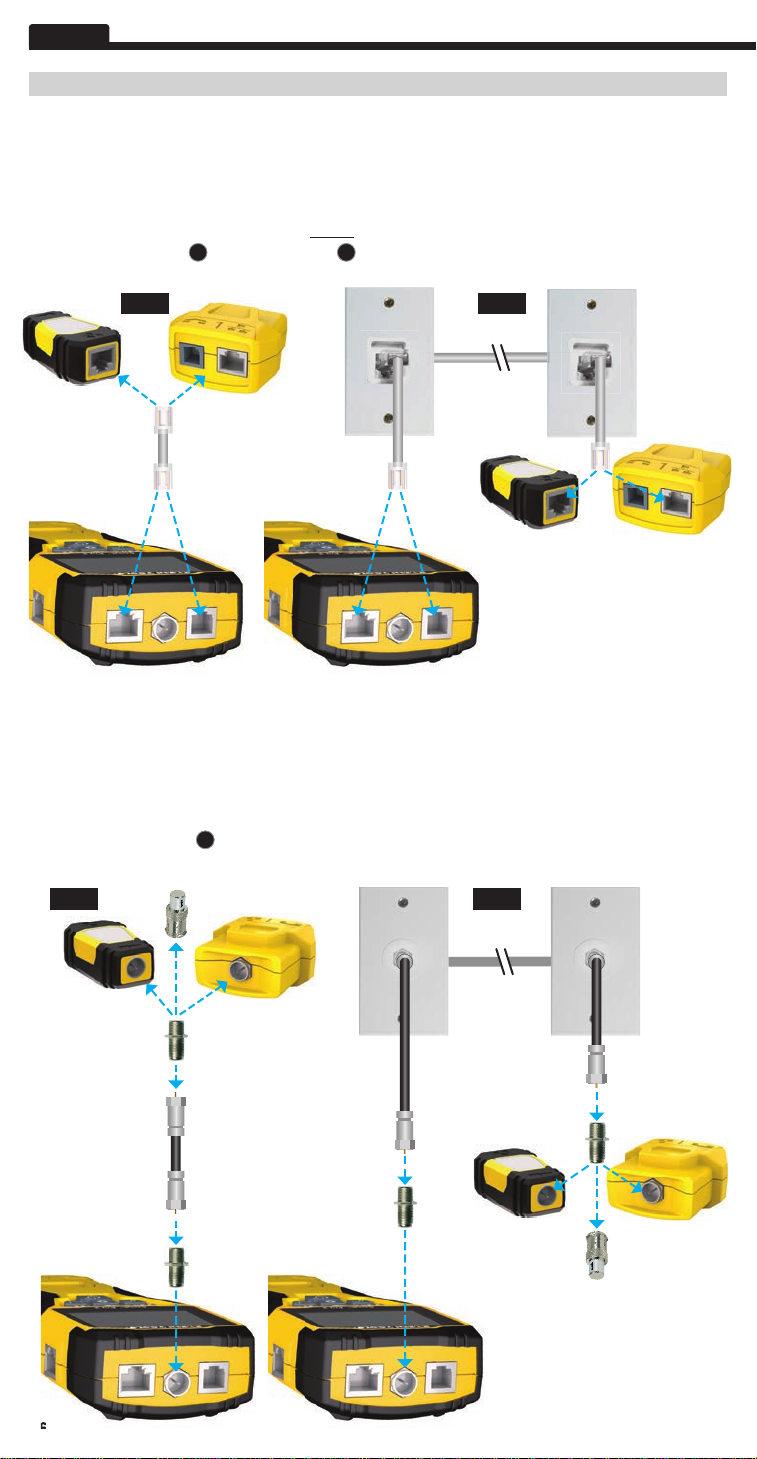
TESTING CONTINUITY ON TERMINATED OR INSTALLED RJ45/RJ11/RJ12 CABLE (FIG. 1, FIG. 2):
1. Connect one end of the cable under test to the RJ45 port (if testing a data cable) or the RJ11/RJ12 port
(if testing a voice cable), located at the top of the main tester body. If testing a wall port, connect a known
good patch cable from the wall plate to the appropriate port at the top of the main tester body.
2. Connect the other end of the cable under test to the corresponding port on the testing remote. If testing
a wall port, connect a known good patch cable from the wall port to the appropriate port on the testing
remote.
NOTE: Location-only ID remotes cannot be used.
3. Press the Data buttonC or the Voice buttonA on the keypad to begin the test.
4. Interpret the results of the test using the WIRING AND DISPLAY EXAMPLES section.
FIG. 1 FIG. 2
-OR-
-OR- -OR-
TESTING CONTINUITY ON TERMINATED OR INSTALLED COAX CABLE (FIG. 3, FIG. 4):
1. Attach female-to-female Barrel Connector to the F-connector port on the top of the tester.
2. Connect one end of the cable to be tested to this adapter.
3. If testing a terminated coax cable, attach a second Barrel Connector to the other end of the cable under
NOTE: This step is not necessary if testing an installed coax cable, or a cable attached to a wall plate.
test.
4. Connect either a numbered CoaxMap™ Location ID Remote or one of the Test + Map™ ID Remotes to the
Barrel Connector.
5. Press the Video buttonB to begin the test.
6. Interpret the results of the test using the WIRING AND DISPLAY EXAMPLES section.
FIG. 4FIG. 3
-OR-
-OR- -OR-
-OR- -OR-
6
OPERATING INSTRUCTIONS
CABLE IDENTIFICATION – DATA AND VOICE CABLES:
It is often necessary to identify cables that branch out from the wiring closet. The VDV Scout
TM
Pro 3 can assist
in two ways:
The first and most convenient way to identify installed cables is by using location ID remotes. Using location ID
remotes, you can trace up to 19 drop locations with one trip to the wiring closet or router. Identification with ID
remotes is done digitally and does not rely on any manual tracing.
The second way to identify cables is by using the VDV Scout
will place a low-frequency voltage on the cable. By using an analog tone probe (Klein Tools VDV500-123, sold
TM
Pro 3's built-in analog tone generator. The tester
separately), a cable can be identified by the tone it is carrying. This technique only allows one cable to be traced
per tone generator, but has additional benefits like the ability to trace unterminated cables of non-standard types.
• LanMap™ Location ID Remotes identify location only.
• CoaxMap™ Location ID Remotes identify location only.
• Test+Map™ ID Remotes identify location, and perform wire map and length tests.
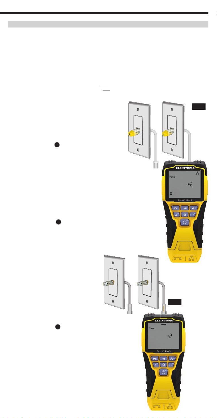
IDENTIFYING INSTALLED RJ45 CABLE (FIG. 5):
1. Insert a numbered LanMap™ Location ID Remote into the
FIG. 5
RJ45 port of each room that needs to be identified. Write
down numbers and room names for later reference.
2. Take the VDV Scout
(the source of the internet connection).
TM
Pro 3 to the wiring closet or router
3. Connect an unknown cable to the RJ45 port on the top
of the tester.
C
4. Press the Data button
will read 'ID#', where '#' is the ID number of the LanMap™
to begin the ID test. The LCD
Location ID Remote connected to the other side of the cable.
Compare this number to the number/room pair list you made
in Step 1 and mark the cable with a piece of labelled tape.
5. Repeat Steps 3 and 4 for each unknown cable until all have been labelled.
You can use these labels to determine which rooms should be connected
to the router, or to troubleshoot intermittent connections in the future.
IDENTIFYING INSTALLED VOICE CABLE (FIG. 5):
1. Insert a numbered LanMap™ Location ID Remote into the RJ45 port of each
room thatneeds to be identified. Write down numbers and room names for
later reference.
2. Take the VDV Scout
internet connection).
TM
Pro 3 to the wiring closet or router (the source of the
3. Connect an unknown cable to the RJ45 port on the top of the tester.
A
4. Press the Voice button
'#' is the ID number of the LanMap™ Location ID Remote connected to the
to begin the ID test. The LCD will read 'ID#', where
other side of the cable. Compare this number to the number/room pair list
you made in Step 1 and mark the cable with a piece of labelled tape.
5. Repeat Steps 3 and 4 for each unknown cable until all have been labelled. You
can use these labels to determine which rooms should be connected to the
router, or to troubleshoot intermittent connections in the future.
IDENTIFYING
INSTALLED COAX CABLE (FIG. 6):
1. Insert a numbered CoaxMap™ Location ID
Remote into the F-connector port of each
room that needs to be identified. Write down
numbers and room names for later reference.
2. Take the VDV ScoutTM Pro 3 to the wiring
closet or cable splitter (the source of the
cable connection).
3. Attach female-to-female Barrel Connector to
FIG. 6
the F-connector port on the top of the tester,
then connect an unknown cable to the Barrel
Connector.
4. Press the Video buttonB to begin the
IDtest. The LCD will read 'ID#', where '#'
isthe ID number of the CoaxMap™ Location
IDRemote connected to the other side of the
cable. Compare this number to the number/
room pair list you made in Step 1 and mark
the cable with a piece of labelled tape.
5. Repeat Steps 3 and 4 for each unknown cable
until all have been labelled.
7

ENGLISH
OPERATING INSTRUCTIONS
TONE TRACING ON INSTALLED RJ45/RJ11/RJ12 CABLE (FIG. 7):
1. Connect a known working patch cable to the RJ45 port (if you are
tracing a Data cable) or RJ12 port (if you are tracing a voice cable)
at the top of the tester.
2. Connect the other end of the patch cable to the wall port at the
satellite location of the cable under test.
3. Short press the Tone button D to
initialise the tone generation. Press
the Tone button
repeatedly to cycle
D
through the available tones, from a
steady low or high tone, to a warbling
slow or fast tone. For voice toning,
repeatedly pressing the Voice/Up
A
button will change the pins or pairs
ofpins the tone is carried on. For data
toning, repeatedly pressing the Data/
C
button will change the pins
Down
or pairs of pins on which the tone is
carried.
4. Use an analog tracing probe (Klein
Tools VDV500-123 recommended,
sold seperately) to determine the
wire or wires on which the tone is
being transmitted (see the Tone
Probe Instruction Manual for details).
The tone will be loudest at the cable
to which the VDV Scout
TM
Pro 3 is
connected. Mark the cable with a label.
5. Repeat Steps 2-6 for each unkown
cable location.
FIG. 7
TONE TRACING ON INSTALLED COAX CABLE (FIG. 8):
1. Attach female-to-female Barrel Connector to the
F-connector port on the top of the tester.
2. Connect a known working patch cable to the Barrel
connector at the top of the main tester body.
3. Connect the other end of the patch cable to the
wall port at the satellite location of the cable
under test.
4. Short Press (for less than 2 seconds)
the Tone buttonD to initialise tone
generation. Press the Tone
buttonD repeatedly to cycle
through the available tones.
Value (in ohms) of the tone
being transmitted will display
on the bottom row.
5. Use an analog tracing probe
to determine the wire on
which the tone is being
transmitted (see the Tone
Probe Instruction Manual
for details). The tone will be
loudest at the cable to which
the VDV ScoutTM Pro 3 is
connected. Mark the cable
with a label.
6. Repeat Steps 2-6 for
each room that has cable
installed.
FIG. 8
8
OPERATING INSTRUCTIONS
TESTING CONTINUITY & CABLE IDENTIFICATION SIMULTANEOUSLY:
The VDV ScoutTM Pro 3 has the capability of simultaneously testing continuity and providing cable location
identification for up to twelve locations with Test + Map™ ID Remotes (sold separately). The VDV ScoutTM Pro 3
series testers come with the Self-Storing Test + Map™ ID Remote No. 1. Test + Map™ ID Remotes No. 2 through
No. 6 are included in some kits (VDV501-853, VDV770-850), Test + Map™ ID Remotes No. 7 through No. 12 are
sold separately in the VDV ScoutTM Pro 3 Test + Map™ ID Remote Kit (VDV770-851).
TESTING CONTINUITY & CABLE IDENTIFICATION SIMULTANEOUSLY – INSTALLED RJ45/RJ11/RJ12 CABLE
1. Attach a numbered Test + Map™ ID Remote to the RJ45/RJ12 port of each room that needs to be identified using
a known good patch cable‡. Write down the number of the remote and of the room number/description in which
it is placed, for comparing/identifying the cables later.
2. Take the VDV ScoutTM Pro 3 to the distribution point (often a wiring closet, switch or router at the other end of the
cable being tested).
3. Connect an unknown cable to the RJ45 port on the top of the tester.
4. Press the Data buttonC or Voice buttonA on the keypad to begin the test on the data or voice cable,
respectively. The LCD will display 'ID#', where '#' is the ID number of the Test + Map™ ID Remote connected to
the other side of the cable.
5. Compare this number to the remote number/room pair list you made in Step 1 and mark the cable with a piece of
labelled tape, print a label or mark with permanent marker. The LCD will also display the results of the continuity
test. These results should be interpreted using the WIRING AND DISPLAY EXAMPLES section.
6. Repeat Steps 4 and 5 for each unknown cable until all cables have been labelled. You can use these labels to determine
which rooms should be connected to the cable splitter, or to troubleshoot intermittent connections in the future.
‡NOTE: Only Klein Tools Universal RJ12 Jumper Cable (VDV726-125) or an approved equivalent should be used in
the RJ45 jack of the Test + Map™ ID Remotes. Using a standard RJ11/12 patch cable in the RJ45 port on the tester
could result in damaged contact pins.
TESTING CONTINUITY & CABLE IDENTIFICATION SIMULTANEOUSLY – INSTALLED COAX CABLE
1. Attach a numbered Test + Map™ ID Remote to the F-connector port of each room. Write down the number of the
remote and of the room number/description in which it is placed, for comparing/identifying the cables later.
2. Take the VDV ScoutTM Pro 3 to the distribution point (often a wiring closet, switch or router at the other end of the
cable being tested).
3. Connect an unknown cable to the Video port on top of the tester using a barrel connector.
4. Press the Video buttonB on the keypad to begin the test on the coax cable. The LCD will display 'ID#' where '#'
is the ID number of the Test + Map™ ID Remote connected to the other side of the cable.
5. Compare this number to the remote number/room pair list that you made in step 1 and mark the cable with a
piece of labelled tape, print a label or mark it with a permanent-ink pen. The LCD will also display the results of
the continuity test. These results should be interpreted using the Wiring and Display Example section
6. Repeat Steps 4 and 5 for each unknown cable until all have been labelled. You can use these labels to determine
which rooms should be connected to the cable splitter, or to troubleshoot intermittent connections in the future.
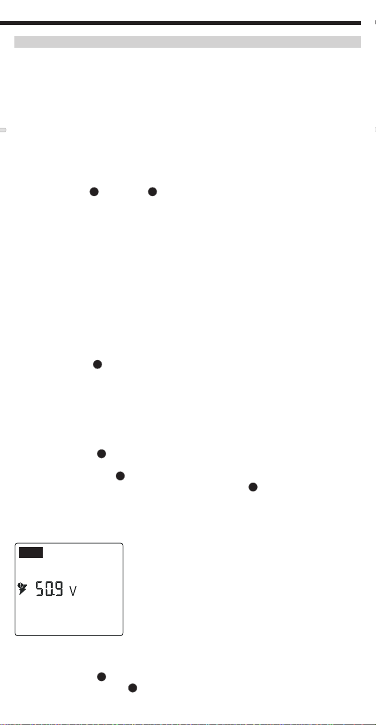
TESTING POWER OVER ETHERNET (PoE)
- (FIG. 9)
1. Press the Power buttonG to turn the tester on.
2. Connect PoE powered Data (RJ45 terminated) cable to the PoE port on right side of tester.
3. Long press the Length buttonF to initiate the PoE test.
4. If power is present, the tester will display the Voltage icon (lightning bolt)14, and the voltage from the PSE
(Power Sourcing Equipment).
5. PoE mode will be displayed 'PoE'or 'PoE+' (see 'IEEE Standard PoE Parameters' chart on the next page
for details).
6. PoE wiring configuration will be displayed: 'A', 'B' or 'AB'.
FIG. 9
A
+
PoE
HUB BLINK FUNCTION
1. Insert RJ45 terminated data cable into RJ45 port on top of tester, connect other end to equipment (hub,
switch, router, etc.).
2. Press the Power buttonG to turn the tester on.
3. Long press (> 1 second) the ToneD button.
4. Signal will be transmitted from tester to equipment to illuminate the corresponding port's light.
9
ENGLISH
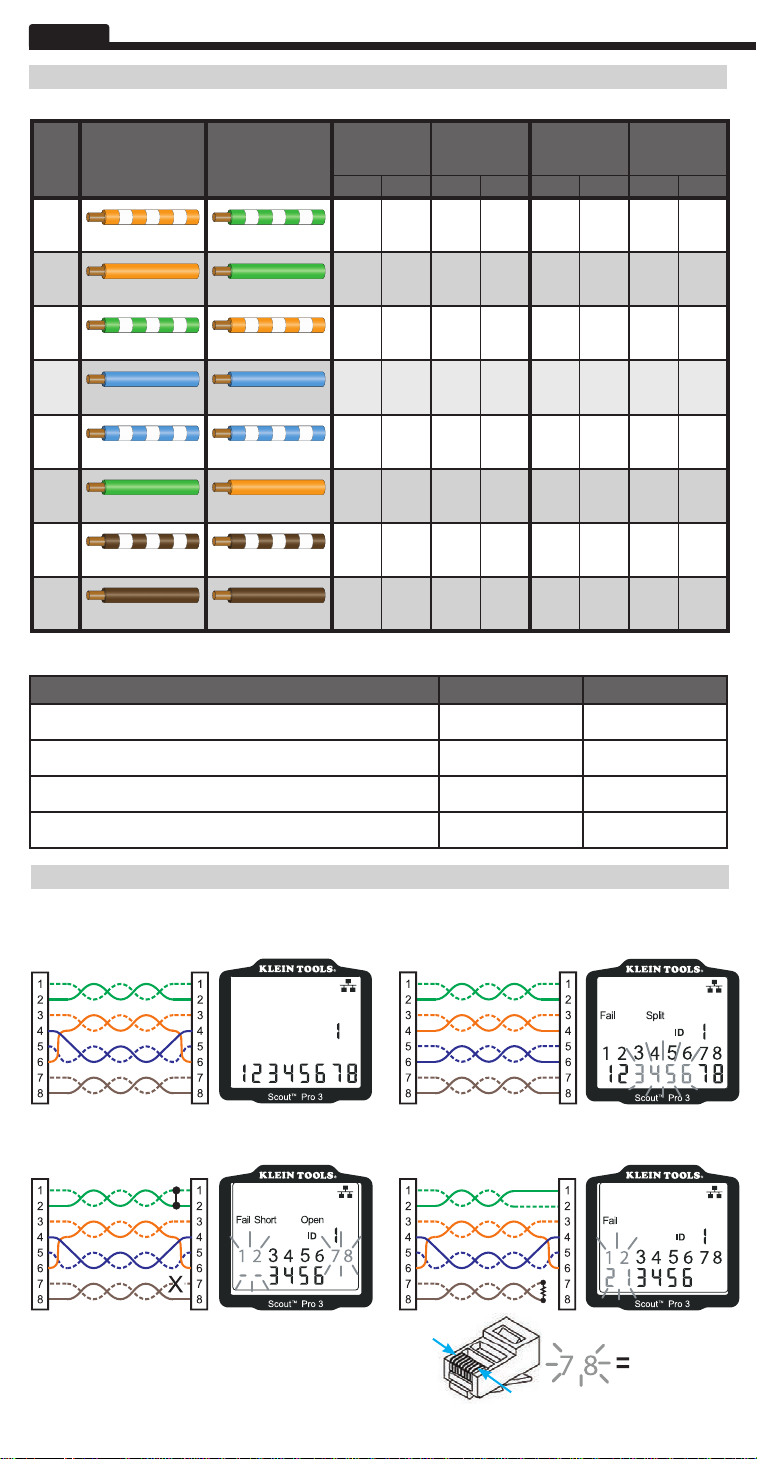
POWER OVER ETHERNET (PoE) REFERENCE CHARTS
POWER OVER ETHERNET (PoE) REFERENCE CHARTS
Pin
TIA/EIA-568
at
T568B Termination
Source
1
White/Orange White/Green
2
3
4 –
5 –
6
7 –
8 –
Orange Verde
White/Green White/Orange
Blue Blue
White/Blue White/Blue
Green Orange
White/Brown White/Brown
Brown Brown
TIA/EIA-568
T568A Termination
10/100
Mode B
DC on Spares
Data Power Data Power Data Power Data Power
Rx+
–
Rx-
–
Tx+
–
DC+
DC+
Tx-
–
DC-
DC-
10/100
Mode A
Mixed DC & Data
Rx+ DC+
Rx- DC+
Tx+ DC-
– –
– –
Tx- DC-
– –
– –
1000 (1 GB)
Mode B
DC & Bi-Data
TxRx
–
A+
TxRx
–
A-
TxRx
–
B+
TxRx
DC+
C+
TxRx
DC+
C-
TxRx
–
B-
TxRx
DC-
D+
TxRx
DC-
D-
1000 (1 GB)
Mode A
DC & Bi-Data
TxRx
DC+
A+
TxRx
DC+
A-
TxRx
DC-
B+
TxRx
TxRx
TxRx
TxRx
TxRx
C+
C-
B-
D+
D-
–
–
DC-
–
–
IEEE Standard PoE Power Parameters
Property 802.3af (PoE) 802.3at (PoE+)
Power available at powered device (PD) 12.95 W 25.50 W
Maximum power delivered by powered device (PD) 15.40 W 30.00 W
Voltage range at powered device (PD) 37.0 to 57 V 42.5 to 57 V
Voltage range at powered device (PD) 44.0 to 57 V 50.0 to 57 V
WIRE MAP AND DISPLAY EXAMPLES
NOTE: Test + Map remote must be used for wire map testing.
PROPERLY WIRED T568A UTP:
Tester
T568A SHORT AND OPEN: T568A MISWIRE & UNRECOGNISED CONTINUITY:
Tester
Remote
Remote
Pass
1 234
ID
5 6
7
T568A SPLIT PAIRS:
Tester
8
Tester
Remote
Remote
NOTE: An open fault or short fault takes precedence
over miswires when the appropriate icon(s) illuminates.
The Split icon illuminates if the cable wiring does not
maintain the designated pairs, an AC signal fault.
10
8
FLASHING
1
WIRE MAP AND DISPLAY EXAMPLES
COAX CABLE PROPERLY WIRED:
COAX CABLE WITH AN OPEN:
COAX CABLE WITH A SHORT:
NOTE: An open
Pass
Open
ID
fault will also
occur when
no remote is
connected to the
Short
satellite end of a
video/coax cable.
BATTERY REPLACEMENT
1. Loosen screw ion battery cover with No. 2 Phillips screwdriver.
2. Remove the battery door.
3. Disconnect the battery cable and recycle the exhausted battery.
4. Install a fresh 9-volt alkaline battery.
5. Connect battery cable to the new battery, observing polarity, and place it into battery
compartment.
6. Replace battery door and secure with a screw, taking care not to over-tighten.
WARRANTY
www.kleintools.com/warranty
CLEANING
Turn the instrument off and disconnect any cables. Clean the instrument using a damp cloth.
Do not use abrasive cleaners or solvents.
STORAGE
Remove the batteries when the instrument is not in use for a prolonged period of time. Do not
expose to high temperatures or humidity. After a period of storage in extreme conditions exceeding the limits mentioned in the Specifications section, allow the instrument to return to normal
operating conditions before using it.
DISPOSAL/RECYCLING
Do not place the equipment and its accessories into a domestic rubbish bin. Items must
be properly disposed of in accordance with local regulations. Please see www.epa.gov or
www.erecycle.org foradditional information.
UPGRADE/REPLACEMENT REMOTES
TEST + MAP™ ID REMOTES (VDV501-2## SERIES)
Use for cable location identification mapping and continuity testing.
Remotes display on tester asRemote ID Nos. 1-12.
2–6
RJ45 port F-connector port
REMOTE ID NO.
1 VDV501-211
2 VDV501-212
3 VDV501-213
4 VDV501-214
5 VDV501-215
6 VDV501-216
7 VDV501-217
8 VDV501-218
9 VDV501-219
10 VDV501-220
11 VDV501-221
12 VDV501-222
2–6 VDV770-850
7–12 VDV770-851
PART NO.
CUSTOMER SERVICE
450 Bond Street, Lincolnshire, IL 60069 1-800-553-4676
KLEIN TOOLS, INC.
www.kleintools.com
11
DEUTSCH
ALLGEMEINE TECHNISCHE DATEN
Der Klein Tools VDV ScoutTM Pro 3 ist ein tragbarer Kabeltester für Sprach-, Daten- und Videokabel. Er dient zur
Prüfung und Fehlersuche bei Kabeln mit RJ11-, RJ12-, RJ45- und F-Steckern und verfügt über einen Tongenerator
zur leichten Kabelverfolgung. Der VDV Scout
Hub-Blink-Tests durch und ortet bis zu 19 Standorte (bis zu 5 Standorte mit mitgelieferten Remote-Einheiten,
zusätzliche Remote-Einheiten separat erhältlich).
Abmessungen: 16,5 x 7,6 x 4,1 cm (6,5 x 3,0 x 1,6Zoll)
•
312 g (11 oz.) einschließlich Batterie und
Gewicht:
•
Remote-Einheit
Betriebstemperatur: 0°C bis 50°C (32°F bis 122°F)
•
Aufbewahrungstemperatur: -20°C bis 60°C
•
Feuchtigkeit: 10% bis 90%, nicht kondensierend
•
Maximale Spannung (zwischen zwei beliebigen
•
Anschlussstiften ohne Beschädigung):
- RJ-Buchse: 66V DC bzw. 55VAC
- F-Steckverbindung: 66V DC bzw. 55VAC
Beachten Sie die folgenden Anweisungen, um einen sicheren Betrieb und eine sichere Wartung des Geräts zu gewährleisten.
Bei Nichtbeachtung dieser Warnungen können schwere bis lebensgefährliche Verletzungen verursacht werden.
Die PoE-Buchse rechts am ScoutTM Pro 3 ist die einzige Buchse zum Anschluss von unter Spannung stehenden PoE-
•
Kabeln. Der Anschluss von unter Spannung stehenden AC-Kabeln an eine der Buchsen kann zur Beschädigung des
Gerätes führen und die Sicherheit des Benutzers gefährden.
Ein unsachgemäßer Abschluss der RJ-Stecker kann zur Beschädigung der Buchsen am VDV Scout
•
Unterziehen Sie die RJ-Stecker vor dem Einstecken in das Prüfgerät immer einer Sichtprüfung. Die Kontakte müssen
unbedingt im Kunststoffgehäuse des Steckers versenkt sein. Werden 6-polige Stecker in die 8-polige Buchse am
Prüfgerät eingesteckt, können die äußeren Kontakte der Buchse beschädigt werden, es sei denn, der 6-polige Stecker ist
speziell für diese Verwendung ausgelegt.
Warnungen oder Vorsichtshinweis
Tragen Sie immer einen zugelassenen Augenschutz. Lesen Sie die Anweisungen.
(-4°F bis 140°F)
TM
Pro 3 misst zudem die Kabellänge, testet auf Schirmung, führt
Batterienutzungsdauer (9-V-Alkalibatterie):
•
- Standby-Betrieb: 4Jahre
- Aktiver Betrieb: 50Stunden
Kabeltypen: Geschirmt oder ungeschirmt; Cat7a, Cat7,
•
Cat6a, Cat6, Cat5e, Cat3, Koaxial
Längenmessverfahren: Kapazität
•
Längenmessbereich:
•
0,5 bis 610 m (1,5 bis 1.999 Fuß) mit 15 pF/ft.
Längengenauigkeit:
•
Längenkonstantenbereich:
•
10 pF/ft. bis 40 pF/ft. (33-132pF/m)
WARNUNGEN
SYMBOLE AUF DEM PRÜFGERÄT
(ohneHintergrundbeleuchtung)
(5 % ft.) oder (5 % m)
TM
Pro 3 führen.
Verwenden Sie das Gerät NICHT an unter
Spannung stehenden Stromkreisen.
EG-Kennzeichnung. Das Gerät entspricht den Richtlinien im europäischen Wirtschaftsraum.
Das Gerät und sämtliches Zubehör müssen getrennt gesammelt und sachgerecht entsorgt werden.
BUCHSEN UND REMOTE-EINHEITEN IM ÜBERBLICK
RJ45-Buchse: Datenkabel, Ethernetkabel, Cat5e, Cat6, Cat6a, Cat7, Cat7a.
F-Buchse: Videokabel, Koaxialkabel, RG6-/RG6Q-Kabel, RG59-Kabel.
RJ11/12-Buchse: Sprachkabel, POTS-Kabel, 4-adriges Kabel, 6-adriges Kabel,
verdrillte Zweidrahtleitung mit 2Paaren, verdrillte Zweidrahtleitung mit 3Paaren, Cat3.
VDV SCOUTTM PRO 3 PRÜFGERÄT REMOTE-ORTUNGSEINHEITEN
Ortung, Identifizierung und Zuordnung von Leitungen.
Set Nr. 1–5 ist im Lieferumfang von VDV500-851
enthalten, Set Nr. 1–18 ist im Lieferumfang von
VDV501-852 enthalten sowie separat erhältlich.
LanMap™
Location RemoteOrtungseinheit**
VDV526-055
CoaxMap™ RemoteOrtungseinheit**
VDV512-056
F-Buchse
RJ45Buchse
**Kann nicht zur Durchführung von Kabelortungen
oder Kabellängentests verwendet werden.
PoE-Buchse*
RJ11/12-Buchse*RJ45-Buchse*
F-Buchse
Buchsenverbinder
VDV814-609
Verbinder F-Buchse auf F-Buchse
STECKVERBINDER
Zur Verwendung mit der F-Buchse
*Die RJ-Buchsen haben gemeinsame interne Anschlüsse. Um die Genauigkeit der Kabelprüfungen sicherzustellen, darf
daher jeweils nur ein RJ-Kabel gleichzeitig angeschlossen sein. Dagegen können ein RJ-Kabel und ein Koaxialkabel
gleichzeitig angeschlossen werden, ohne dass die Genauigkeit beeinträchtigt wird.Im ID-Modus können alle Anschlüsse
am VDV Scout
12
TM
Pro 3 gleichzeitig verbunden sein.

DEUTSCH
SELBSTVERSTAUENDE TEST-N-MAP™ REMOTE-ORTUNGSEINHEIT (VDV501-210)
Ortung, Identifizierung und Zuordnung von Leitungen und/oder Durchgangsprüfungen. Die selbstverstauenden
Remote-Einheiten werden auf dem Prüfer-Display als Remote ID Nr.1 angezeigt. Stets im Lieferumfang von VDV
ScoutTM Pro 3 Modellen enthalten.
RJ11/12-
Buchse
TEST-N-MAP™ REMOTE-ORTUNGSEINHEITEN (VDV501-2XX-SERIE)
Ortung, Identifizierung und Zuordnung von
Leitungen und Durchgangsprüfungen. Die
RJ45-
Buchse
RJ45-
Buchse
F-Buchse
Remote-Ortungseinheiten werden auf dem
Prüfgerät als Remote ID Nr.1–12 angezeigt.
Set Nr. 2–6 ist im Lieferumfang von VDV500853 enthalten und separat erhältlich, Set
Nr. 7–12 ist separat erhältlich, die einzelnen
Remote-Ortungseinheiten Nr. 1–12 sind
separat erhältlich.
TASTENFELDFUNKTIONEN
SCHNELLÜBERSICHT
• SPRACHTASTE/TASTE UPA: Führt eine Prüfung des Verkabelungsplans bei einem
Kabel mit RJ11-/RJ12-Stecker durch, schaltet die Auswahl aufwärts in andere Modi um.
• VIDEOTASTE B: Führt eine Durchgangsprüfung bei einem Koaxialkabel mit
F-Steckverbinder durch.
• DATENTASTE/TASTE DOWNC: Führt eine Prüfung der Wiremap
(Verkabelungsplan) bei einem Kabel mit RJ45-Stecker durch, schaltet
die Auswahl abwärts in andere Modi um.
D
• TONTASTE/HUB-BLINK-TASTE
Tonarten, aktiviert die Hub-Blink-Funktion.
• EINSTELLUNGSTASTE
Modus „Längenkonstante bearbeiten“.
• LÄNGEN-/PoE-TASTEF: Misst die Kabellänge, startet PoE-Prüfung.
• EINSCHALTTASTE/TASTE FÜR HINTERGRUNDBELEUCHTUNGG:
Schaltet das Gerät ein oder aus, schaltet die Hintergrundbeleuchtung ein oder aus.
AUSFÜHRLICHERE ERKLÄRUNG
• SPRACHTASTE/TASTE UPA: Kurzes Drücken: Führt eine Prüfung der Wiremap (Verkabelungsplan) bei einem Kabel mit RJ11-/RJ12-
Stecker durch. Im Ton- oder Längenprüfmodus wählt ein erstes kurzes Drücken den Sprachmodus aus, mehrmaliges kurzes Drücken
wählt Adern oder Adernpaare aus. Langes Drücken: Schaltet den Loop-Modus (Schleifenmodus) ein oder aus. Kehrt im Ton- oder
Längenprüfmodus zur Startansicht zurück. Ändert im Einstellungsmodus die Maßeinheit von Fuß in Meter oder erhöht den Wert der
Längenkonstante.
• VIDEOTASTEB: Kurzes Drücken: Startet eine Durchgangsprüfung an einem Koaxialkabel mit F-Steckverbinder.
Längenprüfmodus wählt ein kurzes Drücken den Videomodus aus.
oder aus. Kehrt im Ton- oder Längenprüfmodus zur Startansicht zurück.
• DATENTASTE/TASTE DOWNC:
Kurzes Drücken: Führt eine Prüfung der Wiremap (Verkabelungsplan) bei einem Kabel mit RJ45-Stecker durch. Im Ton- oder
Längenprüfmodus wählt ein erstes kurzes Drücken den Datenmodus aus, mehrmaliges kurzes Drücken wählt Adern oder Adernpaare
aus. Langes Drücken: Schaltet den Loop-Modus (Schleifenmodus) ein oder aus. Kehrt im Ton- oder Längenprüfmodus zur Startansicht
zurück. Ändert im Einstellungsmodus die Maßeinheit von Fuß in Meter oder erhöht den Wert der Längenkonstante.
• TONTASTE/HUB-BLINK-TASTED: Kurzes Drücken: Mehrmaliges kurzes Drücken schaltet durch die verfügbaren Tonarten. Langes
Drücken: Aktiviert die Hub-Blink-Funktion.
: Schaltet durch die verfügbaren
E
: Wählt Fuß oder Meter aus, schaltet in den
Langes Drücken:
HINWEIS: VERSUCHEN SIE NICHT, die Hub-Blink-Funktion zu verwenden, wenn eine
A
D
E
G
Schaltet den Loop-Modus (Schleifenmodus) ein
B C
Verbindung mit einer aktiven Power-over-Ethernet(PoE)-Buchse vorliegt.
• EINSTELLUNGSTASTEE: Kurzes Drücken: Startet den Modus Längenkonstante bearbeiten (verwenden Sie die Tasten UP
und DOWN C, um den Wert zu ändern). Standardmäßig ist für den Modus Längenkonstante das Adernpaar der Stifte 1 und 2 des
Daten-/RJ45-Kabels und das Adernpaar der Stifte 3 und 4 des Sprach-/Telefonkabels ausgewählt. Weitere Informationen finden Sie im
Abschnitt zur LÄNGENKONSTANTE. Zweites kurzes Drücken: Zeigt die Option für Fuß oder Meter an (verwenden Sie die Tasten UP
und DOWN C, um die Einstellung zu ändern). Weitere Informationen finden Sie im Abschnitt LÄNGENMESSUNG. Langes Drücken:
Beendet den Einstellungsmodus und kehrt zur Startansicht zurück.
• LÄNGEN-/PoE-TASTEF: Kurzes Drücken: Startet die Prüfung der Kabellänge. Bei der Prüfung wird standardmäßig ein mit der
RJ45-Buchse verbundenes Kabel gewählt. Standardmäßig startet die Prüfung bei der ersten Ader ohne vorliegende Fehler. Weitere
Informationen finden Sie in den Abschnitten zur LÄNGENMESSUNG und LÄNGENKONSTANTE.
• EINSCHALTTASTE/TASTE FÜR HINTERGRUNDBELEUCHTUNGG: Kurzes Drücken: Ein erstes kurzes Drücken schaltet das Gerät ein,
mehrmaliges kurzes Drücken schaltet die Hintergrundbeleuchtung ein und aus. Drücken Sie die Einschalttaste ein zweites Mal, um die
LCD-Hintergrundbeleuchtung ein oder auszuschalten.
Langes Drücken: Schaltet das Gerät aus.
HINWEIS: Das Gerät schaltet sich nach 5 Minuten Inaktivität bzw. nach 60Minuten im
Langes Drücken: Startet die PoE-Prüfung.
Tonmodus automatisch aus.
F-Buchse
F
Im Ton- oder
A
A
13
 Loading...