

Page 1
ENGLISH
INSTRUCTION MANUAL - USB DIGITAL METER - TYPE A
GENERAL SPECIFICATIONS
The Klein Tools ET900 is a USB digital multi-meter for USB Type-A ports. It
simultaneously measures and displays the USB port voltage, current, capacity,
energy, and resistance. It can function with any USB Type-A port that has the
ability to deliver power. It requires NO batteries and uses minimal power from
the power source to function, ensuring accurate and reliable readings.
• Measurement Range:
Voltage: 3 to 20V DC Current: 0.05 to 3A
Charge measured: 99,999mAh MAX*
Energy measured: 999Wh MAX*
Resistance: 400Ω MAX
Elapsed Time: Up to 999 hours, 59 min, 59 sec*
*Based on display layout
• Operating and Storage Altitude: Up to 6562 ft. (2000 m)
• Operating and Storage Temp: 14° to 122°F (-10° to 50°C)
• Relative Humidity: <95% non-condensing
• Dimensions: Tester: 2.84" x 1.25" x 0.565" (72 x 32 x 14 mm)
• Weight: 1.1 oz. (31 g)
• Pollution degree: 2
• Drop Protection: 6.6 ft. (2 m)
• Ingress Protection: IP20
• Compatibility: Qualcomm Quick Charge
• Standards:
Specifications subject to change.
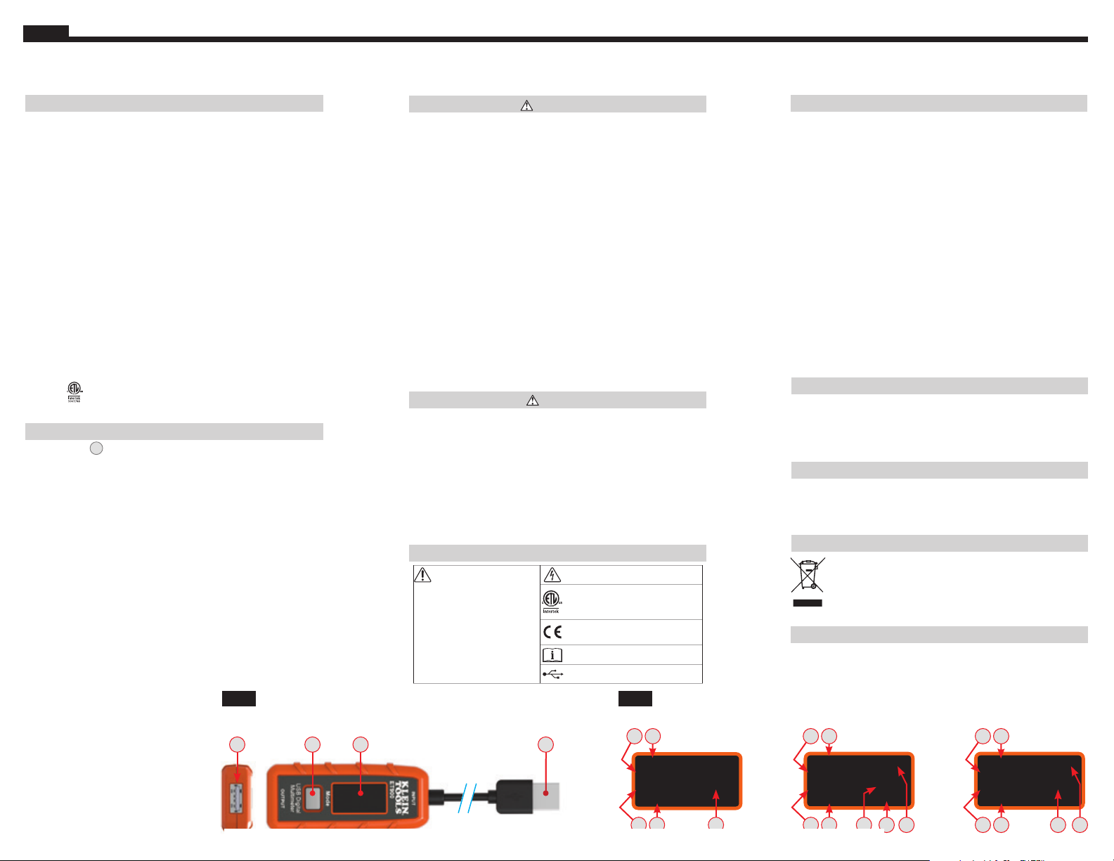
MODE BUTTON 3 (Screen Toggle/Data Storage/Memory reset)
The Mode button serves three purposes:
1. Switch between screens (FIG. 2):
• From the default screen, pressing and releasing once will switch to the
• From the default screen, pressing and releasing twice will switch to the
• When in the Memory Screen, repeated pressing will cycle through all
2. Data/Memory Storage and Recall:
To record a reading during live monitoring event, press and hold the Mode
button for 3 seconds. Release the button after the memory location (i.e. M:1)
flashes momentarily on the screen. The next set of readings will be stored
at the next available location until all 10 memory locations are used.
Once all 10 locations are used, subsequent readings will overwrite them,
beginning with M:1.
3. Memory Reset:
To reset or erase all data in memory, press and hold the Mode button
for 5 seconds from the Memory screen until the letters CLR flash in the
upper right corner (Fig. 2). All data in memory will be erased in all 10
memory locations.
Cable: Approx. 4" (100 mm)
®
EN 61326-1, EN61326-2-2, FCC Part 15B VOC.
Conforms to UL STD. 61010-1, 61010-2-030.
Certified to CSA STD. C22.2 No. 61010-1, 61010-2-030.
Compatible
FUNCTION BUTTONS (FIG. 1)
Enhanced Screen.
Memory Screen.
10 memory locations, beginning with M:1.
NOTE:
WARNINGS
T
o ensure safe operation and service of the tester, follow these
instructions. Failure to observe these warnings can result in
severe injury or death.
• This tester will NOT display current below 50 mA, even if it is
allowing this to pass through.
NOTE: The display will show
zero current.
• DO NOT use with ports that operate outside of the rated voltage
and current .
• Before each use verify tester operation by measuring a known
voltage or current.
• NEVER use on a circuit with voltage or current that exceeds
the maximums specified for this device. (Display will read
"OVERLOAD" in this condition)
• DO NOT use during electrical storms or in wet weather.
• DO NOT use if tester appears to be damaged.
• Use caution when working with voltages above 25V AC RMS
or 60V DC. Such voltages pose a shock hazard.
NOTE: Voltage
above 24V DC will damage product.
• Always adhere to local and national safety codes. Use personal
protective equipment to prevent shock and arc blast injury
where hazardous live conductors are exposed.
CAUTION
• DO NOT attempt to repair this tester. there are no serviceable parts.
• DO NOT modify this tester in any way.
• DO NOT expose to extremes in temperature or high humidity.
• This tester will NOT be able to monitor a source port if any of
the following conditions occur:
• The USB port or plug is not properly connected.
• The source device shuts down. Some portable storage
batteries have auto-shutdown or standby modes to save
power if no load is detected from downstream device.
SYMBOLS ON TESTER
Important information:
It is important that
users of this tester read,
understand, and follow
all warnings, cautions,
safety information, and
instructions in this manual
before operating this
tester. Failure to follow
instructions could result
in death or serious injury.
Warning – Risk of electric shock
This product has been independently
tested by Intertek and meets
applicable published standards
Conformité Européenne: Conforms with
European Economic Area directives
Read instructions before using
USB
ET900
OPERATING INSTRUCTIONS
MONITORING MODE
NOTE: The input plug must be connected to a powered USB
device before the downstream device is connected to the
output port.
the ability to draw current over USB.
1. Connect the input connector to the USB port to be monitored.
• The display will turn on with Klein Tools logo screen and move
quickly to the Default Screen (FIG 2).
• If the source port has power, it should only display a live voltage
reading within the operating range, 3-20V DC.
ports deliver ~5V DC.
2. Connect the device being charged to the output port of the
ET900. The display will show actual readings (FIG. 2).
3. User can monitor in either default or enhanced screens.
Information displayed will differ (FIG. 2).
NOTE: "mAh" resets only when source is disconnected.
Be sure the tester is disconnected from both the input and
output port. Use clean, dry, soft lint-free cloth to wipe down
the entire unit.
Do NOT use abrasive cleaners or solvents.
•
Do not expose to high temperatures or humidity. After a period
of storage in extreme conditions exceeding the limits mentioned
in the General Specifications section, allow the tester to return to
normal operating conditions before using.
"Downstream device" refers to any device that has
NOTE: Most USB
CLEANING
STORAGE
DISPOSAL / RECYCLE
Do not place equipment and its accessories in the trash.
Items must be properly disposed of in accordance with
local regulations. Please see www.epa.gov or www.
erecycle.org for additional information.
1. Power source INPUT (USB-A)
2. Load OUTPUT (USB-A)
3. Mode button
4. LCD display
A. DC voltage
B. DC current
C. Capacity/charge delivered (mAh)
D. Energy delivered (Wh)
E. Resistance (Ω)
F. Elapsed Time (Hour:Min:Sec)
G. Memory Location (M:1, M:2, etc)
H. Memory Clear/Reset ("CLR")
NOTE: No user-serviceable parts inside.
FIG. 1
32 4 1
Find Quality Products Online at: [email protected]
www.GlobalTestSupply.com
FIG. 2
AFB
Vol: ##.## V
Cur: #.## A
###### mAh ####Wh
Tme: ###:##:##
C
Default Screen
D
AFB
##.## V CLR
#.## A
###### mAh ####Wh
###:##:## ###.#Ω
C
Enhanced Screen
ED H
Memory Screen
AFB
Vol: ##.## V M:#
Cur: #.## A
###### mAh ####Wh
Tme: ###:##:##
C G
D
 Loading...