

Page 1
600V
ENGLISH
INSTRUCTION MANUAL
Electronic
AC/DC Voltage Tester
• MODERN
SOLID-STATE
DESIGN
• LOW IMPEDANCE
• DOES NOT
USE A BATTERY
• INTEGRATED
TEST LEAD
HOLDER
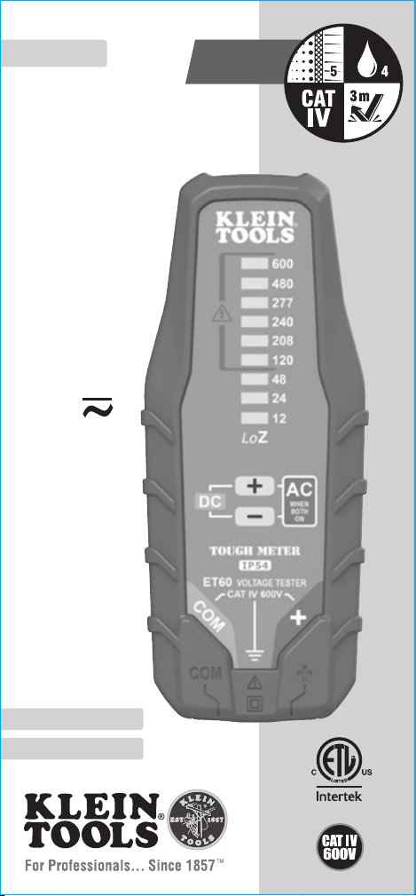
ET60
ESPAÑOL pg. 9
FRANÇAIS pg. 17
Page 2

ENGLISH
GENERAL SPECIFICATIONS
Klein Tools ET60 is a solid-state, low impedance, electronic voltage
tester. It measures AC/DC voltages up to 600V. The ET60 does
not
require batteries; it is powered by the applied voltage.
• Operating Altitude: ≤ 6562 ft. (2000 m)
• Relative Humidity: <90% non-condensing
• Operating Temperature: 5°F to 113°F (-15°C to 45°C)
• Storage Temperature: -4°F to 140°F (-20°C to 60°C)
• Battery Type: None (powered by applied voltage)
• Dimensions: 5.67" x 2.35" x 1.44" (144 x 59.8 x 36.5 mm)
• Weight: 3.2 oz (92 g) without test leads
• Calibration: Accurate for one year
• Standards:
Conforms to: EN61326-1:2013,
EN61326-2-2:2006, EN61010-1:2010,
EN61010-2-030:2010, EN61010-031/A1:2008
• Pollution degree: 2
• Drop Protection: 9.8 ft. (3m)
• Ingress Protection:
IP54 (except test lead jacks, see WARNINGS)
• Safety Rating: CAT IV 600V, Class2, Double insulation
CAT IV: Measurement category IV is applicable to test and
measuring circuits connected at the source of the building’s
low-voltage MAINS installation.
• Electromagnetic Environment: IEC
EN61326-1:2013
. This
equipment meets requirements for use in basic and controlled
electromagnetic environments like residential properties,
business premises, and light-industrial locations.
Specifications subject to change.
2
Page 3

ELECTRICAL SPECIFICATIONS
• Voltage Level Indicators: 12V, 24V, 48V, 120V, 208V, 240V,
277V, 480V, 600V
• Voltage Type Indicators: DC Positive, DC Negative,
both DC polarities "on" indicates AC
• AC Frequency: 45Hz to 66Hz
• Maximum Measurable Voltage:
• Minimum Voltage Detectable:
• Input Impedance:
• Loop Current: 6mA to 9mA at 120V
• Usage Duty Cycle (Above 240V):
followed by 240 seconds (4 minutes) recovery time
• Accuracy: LEDs illuminate fully typically at approx. >90%
of indicated voltage, and will illuminate partially when
approaching this value
16kΩ at 120V (Inherent Low Impedance Testing)
600V RMS (displayed by LEDs)
Approx. 10V AC RMS or 10V DC
30 seconds continuous use
Specifications subject to change.
WARNINGS
To ensure safe operation and service of the meter, follow these
instructions. Failure to observe these warnings can result in
severe injury or death.
• Before each use verify tester operation by measuring a known voltage.
• Never use the tester on a circuit with voltages that exceed the
category based rating of this tester.
• Do not use the tester during electrical storms or in wet weather.
• Do not use the tester or test leads if they appear to be damaged.
• Use only with CAT IV rated test leads.
• Ensure tester leads are fully seated, and keep fingers behind
the finger guards and away from the metal probe contacts
when making measurements.
• Use caution when working with voltages above 25V AC RMS
or 60V DC. Such voltages pose a shock hazard.
• Always adhere to local and national safety codes. Use personal
protective equipment to prevent shock and arc blast injury
where hazardous live conductors are exposed.
• This is a Low Impedance (LoZ) tester, it should not be used in
circuits or situations where damage or adverse effects may be
caused by a ~ 16kΩ load.
• Tester is IP54 dust & water resistant. Following any contact
with water, thoroughly dry tester and test lead jacks prior to
subsequent use.
3
Page 4

ENGLISH
SYMBOLS ON TESTER
AC Alternating Current DC Direct Current
Negative DC Polarity
Positive DC Polarity or
+
Positive Lead Input
Double Insulated Class II Ground
Warning or Caution
LoZ Indicates that this is a low-impedence tester
–
COM Common / Negative Lead Input
Risk of Electrical Shock
FEATURE DETAILS
Back of Tester
Front of Tester
1
4
NOTE: There are no user-serviceable parts inside tester.
Test Lead Holders
1.
Voltage Indicator LEDs
2.
DC Polarity Indicators (indicates AC when both are illuminated)
3.
Test Lead Jacks (bottom of tester)
4.
2
3
4
Page 5
OPERATING INSTRUCTIONS
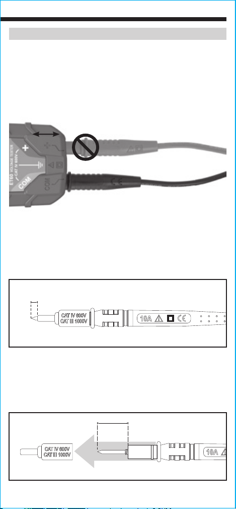
CONNECTING TEST LEADS
Connect test leads by inserting the black lead into the "COM" jack
and the red lead into the "+" jack. Do not test if leads are improperly
seated. Results could cause intermittent display readings. To ensure
proper connection, firmly press leads into the input jack completely.
INCORRECT
CORRECT
TESTING IN CAT III / CAT IV MEASUREMENT LOCATIONS
Ensure the test lead shield is pressed firmly in place. Failure to use
the CATIII / CATIV shield increases arc-flash risk.
5/32"
(4 mm)
TESTING IN CAT II MEASUREMENT LOCATIONS
CAT III / CAT IV shields may be removed for CAT II locations. This
will allow testing on recessed conductors such as standard wall
outlets. Take care not to lose the shields.
.7" (18 mm)
5
Page 6
ENGLISH
OPERATING INSTRUCTIONS
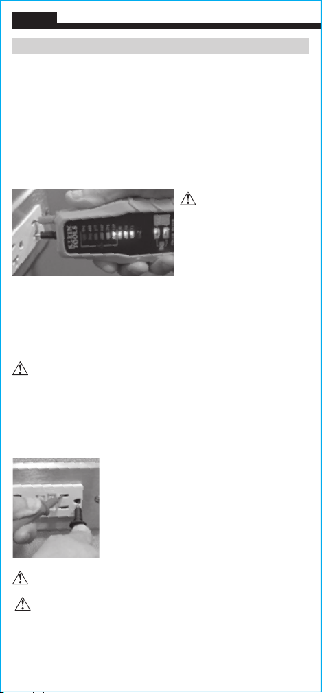
MEASURING VOLTAGE
Apply test leads to the system under test to measure voltage; the
LED’s will light up indicating the voltage present. When DC voltage
is detected the + or – polarity indicator will illuminate revealing
the polarity. When AC voltage is detected, both + and – polarity
indicators will be illuminated at the same time.
NOTE: Test-leads seated in the lead holders on the back of the ET60
are spaced correctly to test tamper-resistant US-style outlets.
Measuring above 240V
should be limited to
30 seconds continuous,
followed by a recommended
recovery time of at least
240 seconds (4 minutes).
GHOST/STRAY VOLTAGES
The low input impedance of ~16kΩ reduces the possibility of falsely
reading ghost or stray voltages on non-energized circuits.
GFCI TESTING
Check the GFCI device user manual for more information.
Always contact a qualied electrician to resolve wiring problems.
Operate the test button on the GFCI device. If the GFCI circuit does
not trip, the device is not functioning properly.
To test the functionality of a GFCI-protected device, apply leads to the
hot/live and ground terminals for 7 seconds.
• If the GFCI device is functioning properly,
the GFCI will trip and the circuit will become
de-energized. The ET60 tester will stop
indicating voltage.
• If the GFCI device is not functioning properly,
the power to the circuit will remain and the
ET60 will continue to indicate voltage
To resolve wiring or GFCI concerns, contact a qualied electrician.
CAUTION: The maximum testing voltage is 600V. Voltages in
excess of 600V will illuminate the 600V LED indicator. No other
warnings will be delivered for voltages above 600V. Testing voltages
above 600V should not be attempted under any circumstances.
6
Page 7

CLEANING
Disconnect test leads. Clean the instrument by using a damp cloth.
Do not use abrasive cleaners or solvents.
STORAGE
Do not expose to high temperatures or humidity. After a period of
storage in extreme conditions exceeding the limits mentioned in
the General Specifications section, allow the instrument to return to
normal operating conditions before use.
WARRANTY
www.kleintools.com/warranty
DISPOSAL / RECYCLE
Do not place equipment and its accessories in the trash.
Items must be properly disposed of in accordance with local
regulations. Please see www.epa.gov or www.erecycle.org
for additional information.
CUSTOMER SERVICE
KLEIN TOOLS, INC.
450 Bond Street
Lincolnshire, IL 60069
1-877-775-5346
customerservice@kleintools.com
www.kleintools.com
7
Page 8

ENGLISH
NOTES
Page 9

600 V
ESPAÑOL
ET60
MANUAL DE INSTRUCCIONES
Probador de voltaje
CA/CD electrónico
• DISEÑO
MODERNO
EN ESTADO SÓLIDO
• BAJA IMPEDANCIA
• NO EMPLEA
BATERÍAS
• SOPORTE PARA
CABLES DE
PRUEBA
INCORPORADO
Page 10

ESPAÑOL
ESPECIFICACIONES GENERALES
ET60 de Klein Tools es un probador de voltaje eléctrico en estado
sólido de baja impedancia. Mide voltaje de CA/CD hasta 600V. ET60
no
requiere el uso de baterías, ya que funciona con el voltaje aplicado.
• Altitud de funcionamiento: ≤ 6562pies (2000m)
• Humedad relativa: <90% sin condensación
• Temperatura de operación: 5°F a 113°F (-15°C a 45°C)
• Temperatura de almacenamiento:
-4°F a 140°F (-20°C a 60°C)
• Tipo de batería: ninguno (funciona con el voltaje aplicado)
• Dimensiones: 5,67" × 2,35" × 1,44" (144 × 59,8 × 36,5mm)
• Peso: 3,2oz (92g) sin los cables de prueba
• Calibración: precisa durante un año
• Normas:
Cumple con: EN61326-1:2013,
EN61326-2-2:2006, EN61010-1:2010,
EN61010-2-030:2010, EN61010-031/A1:2008
• Grado de contaminación: 2
• Protección ante caídas: 9,9pies (3m)
• Protección contra el ingreso de objetos sólidos y líquidos:
IP54 (excepto para los conectores de cables de prueba,
consulte la sección ADVERTENCIAS)
• Clasicación de seguridad: CATIV 600V, clase2,
doble aislamiento
CATIV: La categoría IV de medición es aplicable a los
circuitos de medición y prueba conectados a la fuente de la
instalación de suministro eléctrico de un edificio.
• Entorno electromagnético: IEC
EN61326-1:2013
. Este equipo
cumple con los requisitos apropiados para su uso en entornos
electromagnéticos básicos y controlados como propiedades
residenciales, establecimientos comerciales e instalaciones de
industria ligera.
Especificaciones sujetas a cambios.
10
Page 11

ESPECIFICACIONES ELÉCTRICAS
• Indicadores de nivel de voltaje:
• Indicadores de tipo de voltaje: CD positiva, CD negativa,
• Frecuencia de CA: 45Hz a 66Hz
• Voltaje máximo mensurable: 600VRMS (visualizado mediante LED)
• Voltaje máximo detectable:
• Impedancia de entrada:
• Corriente de bucle: 6mA a 9mA a 120V
• Ciclo de servicio de uso (por encima de 240V):
de uso continuo seguido de 240segundos (4minutos) de
tiempo de recuperación
• Precisión: Los LED se encienden completamente por lo
general a aprox. el 90% del voltaje indicado y parcialmente al
acercarse a este valor.
12V, 24V, 48V, 120V, 208V,
240V, 277V, 480V, 600V
ambas polaridades de CD
encendidas indican CA
aprox. 10VCARMS o 10VCD
16kΩ a 120V
(pruebas de baja impedancia inherentes)
30segundos
Especificaciones sujetas a cambios.
ADVERTENCIAS
Para garantizar un funcionamiento y servicio seguros del multímetro, siga estas
instrucciones. El incumplimiento de estas advertencias puede provocar lesiones
graves o la muerte.
• Antes de cada uso, verifique el funcionamiento del probador midiendo un
voltaje conocido.
• Nunca debe utilizar este probador en un circuito con voltajes que excedan la
clasificación correspondiente a la categoría del probador.
• No utilice el probador durante tormentas eléctricas o en clima húmedo.
• No utilice el probador o los cables de prueba si en apariencia están dañados.
• Utilice el probador con cables de prueba con clasificación CAT IV únicamente.
• Asegúrese de que los cables del probador estén correctamente colocados y
mantenga los dedos detrás del protector y lejos de los contactos de la sonda
de metal al realizar las mediciones.
• Proceda con precaución cuando trabaje con voltajes superiores a 25V CA
RMS o 60V CD. Esos voltajes implican un riesgo de descarga.
• Cumpla siempre con los códigos de seguridad locales y nacionales. Utilice
equipo de protección personal para prevenir lesiones por descarga y arco
eléctrico en los lugares donde haya conductores activos peligrosos expuestos.
• Este instrumento es un probador de baja impedancia (LoZ) que no debe
utilizarse en circuitos o situaciones en que una carga de aproximadamente
16kΩ pueda producir daños o efectos adversos.
• El probador tiene una carcasa IP54 resistente al agua y al polvo. Después
de cualquier contacto con agua, secar cuidadosamente el probador y los
conectores de cables de prueba antes de utilizarlo de nuevo.
11
Page 12

ESPAÑOL
SÍMBOLOS DEL PROBADOR
AC Corriente alterna CD Corriente directa
Polaridad de CD negativa
Polaridad de CD positiva o
+
entrada de conductor positivo
Doble aislamiento Clase II Conexión a tierra
Advertencia o precaución
LoZ Indica que se trata de un probador de baja impedancia.
–
Común/entrada de
COM
conductor negativo
Riesgo de choque eléctrico
DETALLES DE LAS CARACTERÍSTICAS
Parte posterior del probador
Parte frontal del probador
1
4
NOTA: El probador no contiene en su interior
piezas que el usuario pueda reparar.
Soportes para cables de prueba
1.
LED indicadores de voltaje
2.
Indicadores de polaridad de CD
3.
(indican CA cuando ambos están encendidos)
Conectores para cables de prueba (parte inferior del probador)
4.
12
2
3
Page 13

INSTRUCCIONES DE OPERACIÓN
CONEXIÓN DE LOS CABLES DE PRUEBA
Conecte los cables de prueba insertando el cable negro en el
conector "COM" y el cable rojo en el conector "+". No realice
pruebas si los cables no están bien conectados. Los resultados
podrían generar lecturas intermitentes en pantalla. Para garantizar
una buena conexión, presione los cables firmemente en el conector
de entrada hasta el final.
INCORRECTO
CORRECTO
PRUEBAS EN PUNTOS DE MEDICIÓN CON
CLASIFICACIÓN CAT III/CAT IV
Asegúrese de que el blindaje del cable de prueba esté firmemente
colocado en su lugar. No utilizar el blindaje CAT III/CAT IV aumenta
el riesgo de que se produzca un arco eléctrico.
5/32"
(4 mm)
PRUEBAS EN PUNTOS DE MEDICIÓN CON CLASIFICACIÓN CAT II
Es posible retirar blindajes CAT III/CAT IV para realizar mediciones
en puntos con clasificación CAT II. Esto permite efectuar pruebas
en conductores empotrados, como tomacorrientes de pared
estándar. Procure no perder los blindajes.
.7" (18 mm)
0,7" (18 mm)
13
Page 14

ESPAÑOL
INSTRUCCIONES DE OPERACIÓN
VOLTAJE DE MEDICIÓN
Aplique los cables de prueba al sistema que se desea probar para
medir el voltaje; los LED se encenderán para indicar la presencia de
voltaje. Cuando se detecta voltaje CD, el indicador de polaridad + o – se
enciende para indicar la polaridad. Cuando se detecta voltaje CA, ambos
indicadores de polaridad + y – se encienden al mismo tiempo.
NOTA: Los cables de prueba
colocados en los soportes
para cables que se encuentran
en la parte posterior del ET60
están correctamente separados
para probar tomacorrientes
inviolables del tipo que se usa
en Estados Unidos.
Las mediciones por encima de 240V deben limitarse a
30segundos continuos, seguidos de un tiempo de recuperación
recomendado de al menos 240segundos (4minutos).
VOLTAJES FANTASMA/ERRÁTICOS
La baja impedancia de entrada de aproximadamente 16kΩ reduce
la posibilidad de obtener mediciones falsas de voltajes fantasma o
erráticos en circuitos sin corriente.
PRUEBAS DE GFCI
Para más información, consulte el manual
del usuario del dispositivo GFCI. Siempre
comuníquese con un electricista calicado para
solucionar problemas de cableado. Presione
el botón de prueba del dispositivo GFCI. Si el
circuito de GFCI no se acciona, el dispositivo
no está funcionando correctamente.
Para probar la funcionalidad de un dispositivo protegido por GFCI, aplique
cables a los terminales vivos/activos y a tierra durante 7segundos.
• Si el dispositivo GFCI está funcionando correctamente, el GFCI se
accionará y el circuito se desenergizará. El probador ET60 dejará de
indicar el voltaje.
• Si el dispositivo GFCI no está funcionando correctamente, la energía
permanecerá en el circuito y el ET60 continuará indicando el voltaje.
Para resolver problemas de cableado o con el GFCI, comuníquese
con un electricista calicado.
PRECAUCIÓN: El voltaje de prueba máximo es 600V. Ante la
presencia de voltajes mayores que 600V, se encenderá el indicador
LED de 600V. No se emitirán otras advertencias para voltajes
superiores a 600V. En ningún caso se debe intentar probar voltajes
mayores que 600V.
14
Page 15

LIMPIEZA
Desconecte los cables de prueba. Limpie el instrumento con un
paño húmedo.
No utilice solventes ni limpiadores abrasivos.
ALMACENAMIENTO
No lo exponga a la humedad ni a altas temperaturas. Luego de
un período de almacenamiento en condiciones extremas que
sobrepasen los límites mencionados en la sección Especificaciones
generales, deje que el instrumento vuelva a las condiciones de
funcionamiento normales antes de utilizarlo.
GARANTÍA
www.kleintools.com/warranty
ELIMINACIÓN/RECICLAJE
No arroje el equipo ni sus accesorios a la basura.
Los elementos se deben desechar correctamente de
acuerdo con las regulaciones locales. Para obtener más
información, consulte www.epa.gov o www.erecycle.org.
SERVICIO AL CLIENTE
KLEIN TOOLS, INC.
450 Bond Street
Lincolnshire, IL 60069
1-877-775-5346
customerservice@kleintools.com
www.kleintools.com
15
Page 16

ESPAÑOL
NOTAS
Page 17

600 V
FRANÇAIS
MANUEL D’UTILISATION
Testeur de tension
c.a./c.c. électronique
• CONCEPTION
MODERNE À SEMICONDUCTEURS
• FAIBLE IMPÉDANCE
• NE REQUIERT
PAS DE BATTERIE
• PORTE-FIL DE
TEST INTÉGRÉ
ET60
Page 18

FRANÇAIS
CARACTÉRISTIQUES GÉNÉRALES
Le ET60 de KleinTools est un testeur de tension électronique à
semi-conducteurs et à faible impédance. Il permet de mesurer des
aucune
tensions c.a/c.c. inférieures à 600V. Le ET60 ne requiert
batterie; il est alimenté par la tension appliquée.
• Altitude de fonctionnement: ≤2000m (6562pi)
• Humidité relative: <90% (sans condensation)
• Température de fonctionnement: -15°C à 45°C (5°F à 113°F)
• Température d’entreposage: -20°C à 60°C (-4°F à 140°F)
• Type de pile: aucune (alimenté par la tension appliquée)
• Dimensions: 144 x 59,8 x 36,5mm (5,67 x 2,35 x 1,44po)
• Poids: 92g (3,2oz) sans les fils de test
• Étalonnage: précis pendant unan
• Normes:
conforme aux normes: EN61326-1:2013,
EN61326-2-2:2006, EN61010-1:2010,
EN61010-2-030:2010, EN61010-031/A1:2008
• Niveau de pollution: 2
• Protection contre les chutes: 3m (9,9pi)
• Protection contre les inltrations:
IP54 (à l’exception des
fiches de fils de test, voir les AVERTISSEMENTS)
• Cote de sécurité: CAT.IV 600V, classe2, double isolation
CAT. IV: la catégorie de mesureIV est applicable aux circuits
de test et de mesure branchés à la source de l’installation du
RÉSEAU basse tension du bâtiment.
• Environnement électromagnétique: IEC
EN61326-1:2013
.
Cet équipement répond aux exigences pour une utilisation
dans des environnements électromagnétiques ordinaires
et contrôlés comme les zones résidentielles, les locaux
commerciaux et les sites industriels légers.
Les caractéristiques techniques peuvent faire l’objet de modifications.
18
Page 19

SPÉCIFICATIONS ÉLECTRIQUES
• Indicateurs de niveau de tension:
• Indicateurs de type de tension: c.c. positive, c.c. négative,
• Fréquence c.a.: 45Hz à 66Hz
• Tension mesurable maximale: 600V valeur efficace (affichée par DEL)
• Tension minimale détectable: environ 10Vc.a. (valeur efficace)
• Impédance en entrée:
• Courant de ligne: de 6mA à 9mA, à 120V
• Cycle de service lors de l’utilisation (tension supérieure à 240V):
utilisation continue de 30secondes suivie d’un temps de
récupération de 240secondes (4minutes)
• Précision: les DEL émettent généralement le maximum de lumière
à une tension supérieure à90% de la tension indiquée, et allument
partiellement à une tension près de cette valeur
16kΩ à 120V (test à faible impédance inhérente)
12V, 24V, 48V, 120V, 208V,
240V, 277V, 480V, 600V
les deux s’allument pour
indiquer un c.a.
ou 10Vc.c.
Les caractéristiques techniques peuvent faire l’objet de modifications.
AVERTISSEMENTS
Pour garantir une utilisation et un entretien du multimètre sécuritaires, suivez ces
instructions. Le non-respect de ces avertissements peut entraîner des blessures
graves, voire la mort.
• Avant chaque usage, vérifiez le bon fonctionnement du testeur en mesurant
une tension dont vous connaissez la valeur.
• N’utilisez jamais le testeur dans un circuit dont la tension dépasse celle
correspondant à sa cote de sécurité.
• N’utilisez pas le testeur pendant des orages électriques ou dans des
conditions humides.
• N’utilisez pas le testeur ou les fils de test s’ils ont l’air endommagés.
• Utilisez uniquement des fils de test conformes à la norme CAT.IV.
• Lorsque vous prenez des mesures, assurez-vous que les fils du testeur sont
solidement en place et gardez les doigts derrière les protecteurs pour doigts et
éloignés des contacts métalliques des sondes.
• Faites preuve de prudence lors de mesures sur des circuits de plus de 25Vc.a.
RMS ou de 60Vc.c. De telles tensions constituent un risque de choc électrique.
• Assurez-vous de respecter en tout temps les codes de sécurité locaux et
nationaux. Utilisez de l’équipement de protection individuelle pour prévenir des
blessures causées par les chocs électriques et les arcs électriques lorsque des
conducteurs nus alimentés dangereux sont présents.
• Il s’agit d’un testeur à faible impédance: vous ne devez pas l’utiliser dans
des circuits ou situations où une charge d’environ 16kΩ est susceptible de
provoquer des dommages ou des effets indésirables.
• Ce testeur est conforme à la normeIP54 en ce qui concerne la résistance à
l’eau et à la poussière. En cas de contact avec l’eau, sécher le testeur et les fils
de test avant de l’utiliser à nouveau.
19
Page 20

FRANÇAIS
SYMBOLES SUR LE TESTEUR:
AC Courant alternatif DC Courant continu
Polarité c.c. positive
Polarité c.c. positive ou
+
entrée positive pour l
Double isolation, classeII Mise à la masse
Avertissement ou
mise en garde
LoZ Indique qu’il s’agit d’un testeur à faible impédance
–
COM Entrée commune/négative pour l
Risque de choc électrique
CARACTÉRISTIQUES DÉTAILLÉES
Endos du testeur
Avant du testeur
1
4
REMARQUE: ce testeur ne contient aucune
pièce réparable par l’utilisateur.
Porte-fils de test
1.
DEL indicatrices de tension
2.
Indicateurs de polarité c.c.
3.
Prises pour fils de test (dessous du testeur)
4.
(les deux s’allument pour indiquer un c.a.)
2
3
20
Page 21

INSTRUCTIONS D’UTILISATION
BRANCHEMENT DES FILS DE TEST
Branchez les fils de test en insérant le fil noir dans la prise
commune (COM) et le fil rouge dans la prise positive (+).
N’effectuez pas de test si les fils de test ne sont pas installés
correctement. Cela pourrait causer des lectures intermittentes. Pour
assurer un raccordement approprié, enfoncez complètement les fils
de test dans la prise d’entrée.
INCORRECT
CORRECT
TESTS DANS DES EMPLACEMENTS CAT.III/CAT.IV
Assurez-vous que l’écran de protection des fils de test est enfoncé
complètement. Le fait de ne pas utiliser l’écran de protection
CAT.III/CAT.IV augmente le risque d’arc électrique.
4 mm
5/32"
(5/32 po)
(4 mm)
TESTS DANS DES EMPLACEMENTS CAT.II
Les écrans de protection CAT.III/CAT.IV peuvent être retirés des
emplacements CAT.II pour effectuer des tests sur des conducteurs
encastrés, p.ex. les prises murales standard. Assurez-vous de ne
pas perdre les écrans de protection.
18 mm (0,7 po)
.7" (18 mm)
21
Page 22

FRANÇAIS
INSTRUCTIONS D’UTILISATION
MESURE DE LA TENSION
Branchez les fils dans le système à tester pour mesurer la tension; la
DEL s’allumera et en indiquera la valeur. Lorsque l’appareil détectera
une tension c.c., l’indicateur de polarité + ou – s’allumera pour
indiquer la polarité. Lorsque l’appareil détectera une tension c.a., les
deux indicateurs de polarité, soit + et –, s’allumeront en même temps.
REMARQUE:
les porte-fils de test à l’arrière du ET60 sont suffisamment
espacés pour tester les modèles américains de prises inviolables.
Les mesures de tensions
au-delà de 240V ne doivent
pas être prises pendant plus
de 30secondes continues et
il est recommandé d’allouer
un temps de récupération
d’au moins 240secondes
(4minutes).
TENSIONS FANTÔMES OU PARASITES
La faible impédance du signal d’entrée d’environ 16kΩ réduit le
risque de lecture à tort des tensions fantômes ou parasites sur
des circuits hors tension.
TEST DE DISJONCTEUR DE FUITE DE TERRE (GFCI)
Pour en savoir plus, consultez le manuel de
l’utilisateur de l’appareil avec disjoncteur de fuite
de terre. Communiquez toujours avec un électricien
qualié pour résoudre les problèmes de câblage.
Appuyez sur le bouton de test de l’appareil. Si
le circuit du disjoncteur de fuite de terre ne se
déclenche pas, l’appareil ne fonctionne pas
correctement.
Afin de tester le fonctionnement d’un appareil protégé par un disjoncteur de fuite
de terre, branchez les fils dans la borne chargée/sous-tension et dans la borne
de mise à la terre pendant 7 secondes.
• Si l’appareil fonctionne correctement, le disjoncteur se déclenchera et le
circuit sera mis hors tension. Le testeurET60 n’indiquera plus de tension.
• Si l’appareil ne fonctionne pas correctement, l’alimentation du circuit ne sera
pas coupée et le ET60 continuera d’indiquer une tension.
Communiquez toujours avec un électricien qualié pour résoudre les
problèmes de câblage ou de prise avec disjoncteur de mise à la terre.
MISE EN GARDE: la tension maximale testable est de 600V. Les
tensions au-delà de 600V feront allumer l’indicateur DEL de 600V. Il n’y
aura aucun autre avertissement que la tension dépasse 600V. Vous ne
devriez en aucun cas tester des tensions au-delà de 600V.
22
Page 23

NETTOYAGE
Débranchez les fils de test. Nettoyez l’appareil à l’aide d’un chiffon
humide.
N’utilisez pas de nettoyant abrasif ou de solvant.
RANGEMENT
N’exposez pas l’appareil à des températures élevées ou à un
taux d’humidité élevé. Après l’avoir rangé dans des conditions
extrêmes qui dépassent les limites mentionnées dans la section
Caractéristiques générales, laissez l’appareil revenir à des
conditions d’utilisation normales avant de l’utiliser.
GARANTIE
www.kleintools.com/warranty
MISE AU REBUT/RECYCLAGE
Ne pas mettre l’appareil et ses accessoires au rebut.
Ces articles doivent être éliminés conformément aux
règlements locaux. Pour de plus amples renseignements,
consultez les sites www.epa.gov ou www.erecycle.org.
SERVICE À LA CLIENTÈLE
KLEIN TOOLS, INC.
450 Bond Street
Lincolnshire, IL 60069
1877775-5346
customerservice@kleintools.com
www.kleintools.com
23
Page 24

KLEIN TOOLS, INC.
450 Bond Street
Lincolnshire, IL 60069
1-877-775-5346
customerservice@kleintools.com
www.kleintools.com
1390174 Rev 04/18 E
 Loading...