


ENGLISH
CONTENTS
• 29610 PowerHub 1
• Instruction Sheet
• Hang Tag
PowerHub 1 - Instructions
PowerHub 1 - Instrucciones
PowerHub 1 – Instructions
GENERAL SPECIFICATIONS
• AC Input: NEMA 5-15P, Nominal 120V AC, 15A, 60Hz. Use with 15A rated, 5-25'
(1.5-7.6 m) long cord
• Maximum Total Power Output: 1875W
• AC Output: 6 × NEMA 5-15R, Nominal 120V AC, 15A, 60Hz, Max. output 1875W
• Surge Protection: 2160 Joules
• GFCI Type: Auto monitor. Auto reset, trip time 0.025 seconds (nominal)
• Overcurrent Protection: 15A
• USB Output (Total Wattage): 42W
• USB-A: 1× 12W (5V DC, 2.4A) or 2 × 6W (5V DC, 1.2A)
• USB-C: 2× 15W max (5V DC, 3.0A max)
• LED Work Light Output: 5,000 Lumens
• Rotational Range of Work Light: +75°, -15° from horizontal
• Operating Temperature: 14°F to 122°F (-10°C to 50°C)
• Storage Temperature: -4°F to 158°F (-20°C to 70°C)
• Operating / Storage Maximum Altitude: 2,000 m (6,562')
• Operating / Storage Maximum Humidity: 85% non-condensing
• Dimensions: 14" × 14" × 25" (35.6 cm × 35.6 cm × 63.5 cm)
• Weight: 15.1 lb (6.9kg)
• Device Shelf Max Capacity: 5 lbs (2.3kg)
3
• Drop Protection: 3.3' (1m)
• Standards: CONFORMS TO UL STD, 1363, 1449, 153,
CERTIFIED TO CSA STD, C22.2#308:2018, C22.2#269.3:2017,
5
C22.2#250.4:2020
WARNINGS
Read, understand, and follow these instructions to ensure safe
8
operation and service of the PowerHub 1.
Failure to observe these warnings can result in re, electric shock,
property damage, serious injury and/or death.
• TO REDUCE THE RISK OF ELECTRIC SHOCK, USE ONLY INDOORS. DO
NOT EXPOSE TO RAIN OR SNOW.
• R
ISK OF ELECTRIC SHOCK. DO NOT PLUG INTO ANOTHER
RELOCATABLE POWER TAP. PLUG INTO ONLY ONE 15A RATED
EXETNSION CORD, 5-25' (1.5-7.6m) IN LENGTH
• DO NOT
• DO NOT
• DO NOT
• DO NOT
• DO NOT
• Avoid touching or placing any objects on hot surfaces near LED work
• DO NOT
• DO NOT look directly into the LED work light.
• Keep away from high voltage devices.
exceed maximum power rating of device (1875W).
use the product if damaged or modified.
connect to an ungrounded outlet.
use with extension cord adapters that eliminate the
connection to ground.
use near flammable liquids or gases.
light or its housing.
attempt to insert other USB connector types into the USB-C
or USB-A ports.
CLEANING: Be sure device is disconnected from all power sources and
devices. Use clean, dry, soft, lint-free cloth to wipe down the entire unit.
Do not use abrasive cleaners or solvents.
STORAGE:
70°C), less than 85% relative humidity, and away from direct sunlight
(See GENERAL SPECIFICATIONS). Leaving in a vehicle or other confined
spaces in extreme hot temperatures can lead to decrease in service
life, overheating, or fire. Extreme cold temperatures below the specified
storage range can also harm performance and service life. Keep away
from corrosive chemicals and gases. After taking out of storage, inspect
visually to make sure device and all accessories look satisfactory. Allow
unit to return to ambient conditions before using.
• CAUTION - DO NOT install this device if there is not at least 10
meters (33') or more of wire between the electrical outlet and the
electrical service panel.
• This device features an internal protection that will disconnect the
Do not place equipment and its accessories in the trash or in
curbside recycle bin. Items must be properly recycled of in
accordance with local regulations. Please see
for additional information.
surge protective component at the end of its useful life, but will
maintain power to the load – now unprotected.
10
MAINTENANCE
Store at temperatures between -4°F and 158°F (-20°C and
DISPOSAL / RECYCLE
OPERATING INSTRUCTIONS
PLEASE SEE REVERSE SIDE.
29610
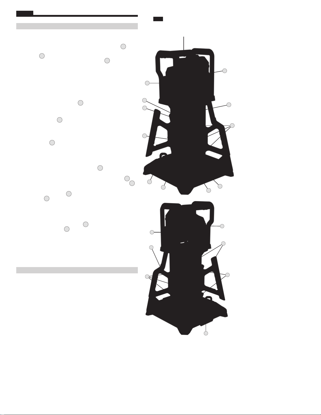
FIG. A
FRONT / FRENTE / AVANT
4
1
3
11
12
13
2
6
7
9
15
SYMBOLS ON PRODUCT
13
Warning or Caution
Risk of Electrical Shock
Read Instructions
Level VI Efficiency Standard
FEATURE DETAILS (FIG.A)
1. Work Light
2. Work Light ON/OFF Button
3. Work Light Tightening Knob
4. Top Grab Handle
5. Side Grab Handle (×2)
6. Integrated Cord Wrap (×2)
7.
Extension Cord Plug Hook (×2)
8. AC Outlet (×6)
9.
USB Ports
10.
AC Input
11.
GFCI Test/Reset Button
GFCI Indicator LED
12.
NOTE: GFCI Indicator LED will illuminate
RED to indicate
13.
Device Shelves (×3)
14.
120V Outlet ON/OFF Switch
power is on.
14
8
16
15.
Surge Protected LED Status Indicator
16.
Grounded Input LED Indicator
Find Quality Products Online at: sales@GlobalTestSupply.com
www.GlobalTestSupply.com
ENGLISH
OPERATING INSTRUCTIONS
FIG. A
FRONT / FRENTE / AVANT
POWERING AND SETTING UP THE POWERHUB 1:
• Place unit on firm, level ground. Plug a powered, 15A rated , 5-25' long
(1.5-7.6 m), 120V AC power cord into PowerHub 1’s AC Input 10 to
supply power to the unit. When powered, the Surge Protection LED
Indicator 15 will illuminate to show that the outputs are protected from
input voltage surges, and the Ground LED Indicator
will illuminate if
16
the input AC source is grounded. When PowerHub 1 is supplied power,
the USB circuit will be activated automatically.
• Ensure connected power cords do not create trip hazard.
• Refer to your equipment user manual(s) to ensure combined,
connected load is less than 1875W total.
OPERATING THE POWERHUB 1:
• Once powered, turn the power distribution circuit on by toggling
the 120V Outlet ON/OFF Switch 14 to the ON position. This switch
provides power to the 6 × 120V outlets and illuminates when in the
11
12
ON position.
NOTE: If the switch 14 is in the ON position and illuminated, but
the 120V outlets are not providing power, refer to the Resetting and
Testing Section
• Once powered, the LED Work Light is activated with the Work Light
13
ON/OFF Button 2.
RESETTING AND TESTING THE GFCI AND OVERCURRENT PROTECTION
• If triggered by a ground fault, the built-in GFCI unit will deactivate
power out of the PowerHub 1’s 120V outlets. To reactivate power
to the PowerHub 1, remove the faulty device from the PowerHub
1’s circuit, then press the GFCI Reset Button
to re-energize the
11
PowerHub 1’s outlets.
• GFCI functionality can be tested by pressing the TEST button 11 to
disconnect output power from the device and the RESET button
11
to re-establish output power.
• If the GFCI LED Indicator
is illuminated, but the 120V Outlet ON/
12
OFF Switch 14 is in the ON position and not illuminated, remove
all connected devices and toggle the 120V Outlet ON/OFF Switch to
reset the PowerHub 1’s overcurrent protection.
USING THE INTEGRATED POWER CORD WRAP
• While they are not in use, power cords can be stored on the PowerHub 1
by inserting one plug into a plug hook 7 and looping the cord around
the Integrated Cord Wrap 6.
USING THE PORTABLE DEVICE SHELVES
• The portable device shelves are intended to elevate small electronics
off the ground while charging. Before resting your portable devices
in the shelves, please ensure that it does not exceed the maximum
weight rating for each self. Once positioned, ensure the portable
device is not at risk of falling off support arm, particularly if bumped.
4
1
3
14
8
7
9
3
5
16
15
2
6
COMPLIANCE
This device complies with part 15 of the FCC RULES and Industry Canada
license-exempt RSS standard(s). Operation is subject to the following two
conditions: (1) this device may not cause harmful interference, and (2) this
device must accept any interference received, including interference that
may cause undesired operation.
NOTE: The grantee is not responsible for any changes or modifications not
expressly approved by the party responsible for compliance. Such
modifications could void the user’s authority to operate the equipment.
This equipment has been tested and found to comply with the limits
for a Class B digital device, pursuant to part 15 of the FCC Rules. These
limits are designed to provide reasonable protection against harmful
interference in a residential installation. This equipment generates, uses
and can radiate radio frequency energy and, if not installed and used in
accordance with the instructions, may cause harmful interference to radio
communications. However, there is no guarantee that interference will not
occur in a particular installation. If this equipment does cause harmful
interference to radio or television reception, which can be determined by
turning the equipment off and on, the user is encouraged to try to correct
the interference by one or more of the following measures:
• Reorient or relocate the receiving antenna.
•
Increase the separation between the equipment and receiver.
•
Connect the equipment into an outlet on a circuit different from that
to which the receiver is connected.
•
Consult the dealer or an experienced radio/TV technician for help.
Canada ICES-003 (B) / NMB-003 (B)
ICES-005 (B) / NMB-005 (B)
Find Quality Products Online at: sales@GlobalTestSupply.com
www.GlobalTestSupply.com
8
10
13
 Loading...