

Page 1

HYDROCHART 5000 SONAR
SYSTEM
Operations and Maintenance Manual
P/N 11210080, Rev. 02
11 Klein Drive
Salem, NH 03079-1249
U.S.A.
Tel: (603) 893-6131
Fax: (603) 893-8807
www.KleinMarineSystems.com
Page 2

ii
This document contains proprietary information, and such information may not be
disclosed to others for any purpose or used for any manufacturing purpose without
expressed written permission from Klein Marine Systems, Inc. (KMS). The
information provided is for informational purposes only and is subject to change
without notice. KMS assumes no responsibility or liability for any errors,
inaccuracies or omissions that may be present in this document.
The SonarPro software program may be used or copied only in accordance with
the terms of the Software License Agreement.
©
Copyright 2010–2019 by Klein Marine Systems, Inc. All rights reserved.
SonarPro® is a registered trademark of Klein Marine Systems, Inc.
Intel® and Pentium®are registered trademarks of Intel Corporation.
Windows® is a registered trademark of Microsoft Corporation.
vxWorks® is a registered trademark of Wind River Systems, Inc.
Kevlar® is a registered trademark of the DuPont Company.
\HydroChart 5000 Sonar Operations and Maintenance Manual P/N 11210080, Rev. 02
Page 3

WARNING
Klein Marine Systems recommends all troubleshooting be done by
a trained technician. Some circuits in the Transceiver and
Processing Unit (TPU) have voltages as high as 240 volts, and
some circuits in the sonar Sonar Head Unit have 1500 volts. You
should familiarize yourself with the location of these voltages
before you attempt any troubleshooting. Failure to observe these
warnings could result in injuries to personnel.
CAUTION
Serious damage to the sonar electronics may occur if the Sonar
Head Unit is operated out of the water for periods longer than
15 minutes. Let the sonar cool 15 minutes or longer between
operations. Protect the Sonar Head Unit from direct exposure to the
sun prior to and during operation in high temperature climates.
iii
CAUTION
The depth rating on the transducers is 200 meters (656 feet).
Operations at depths greater than 200 meters may damage the
transducers.
Page 4

iv
Table of Contents
Table of Contents . . . . . . . . . . . . . . . . . . . . . . . . . . . . . . . . . . . . . . . . . . . . iv
List of Figures . . . . . . . . . . . . . . . . . . . . . . . . . . . . . . . . . . . . . . . . . . . . . . viii
List of Tables . . . . . . . . . . . . . . . . . . . . . . . . . . . . . . . . . . . . . . . . . . . . . . . . x
Sonar System Warranty . . . . . . . . . . . . . . . . . . . . . . . . . . . . . . . . . . . . . . . xi
What Is Covered . . . . . . . . . . . . . . . . . . . . . . . . . . . . . . . . . . . . . . . . . . . xi
Conditions Of Warranty . . . . . . . . . . . . . . . . . . . . . . . . . . . . . . . . . . . . xii
Changes, Errors And Omissions . . . . . . . . . . . . . . . . . . . . . . . . . . . . . . xiii
Software License Agreement . . . . . . . . . . . . . . . . . . . . . . . . . . . . . . . . . . xiv
Preface . . . . . . . . . . . . . . . . . . . . . . . . . . . . . . . . . . . . . . . . . . . . . . . . . . . xvi
What’s in This Manual . . . . . . . . . . . . . . . . . . . . . . . . . . . . . . . . . . . . . xvi
Note, Warning, Caution, and Shock Hazard Notices . . . . . . . . . . . . . xvii
Customer Service . . . . . . . . . . . . . . . . . . . . . . . . . . . . . . . . . . . . . . . . . . xvii
CHAPTER 1: Overview . . . . . . . . . . . . . . . . . . . . . . . . . . . . . . . . . . . 1-1
1.1 Equipment . . . . . . . . . . . . . . . . . . . . . . . . . . . . . . . . . . . . . . . . . 1-1
1.1.1 Sonar Head Unit . . . . . . . . . . . . . . . . . . . . . . . . . . . . . . . . . . . 1-1
1.1.2 TPU . . . . . . . . . . . . . . . . . . . . . . . . . . . . . . . . . . . . . . . . . . . . . 1-1
1.1.3 SonarPro Workstation . . . . . . . . . . . . . . . . . . . . . . . . . . . . . . 1-2
1.1.4 Deck Cable . . . . . . . . . . . . . . . . . . . . . . . . . . . . . . . . . . . . . . . 1-2
1.2 Features . . . . . . . . . . . . . . . . . . . . . . . . . . . . . . . . . . . . . . . . . . . 1-2
1.3 Surface Equipment . . . . . . . . . . . . . . . . . . . . . . . . . . . . . . . . . . . 1-3
1.4 Subsurface Equipment . . . . . . . . . . . . . . . . . . . . . . . . . . . . . . . . 1-3
1.5 Technical Description . . . . . . . . . . . . . . . . . . . . . . . . . . . . . . . . 1-5
1.5.1 Sonar Head Unit . . . . . . . . . . . . . . . . . . . . . . . . . . . . . . . . . . . 1-5
1.5.2 TPU . . . . . . . . . . . . . . . . . . . . . . . . . . . . . . . . . . . . . . . . . . . . . 1-8
CHAPTER 2: Specifications . . . . . . . . . . . . . . . . . . . . . . . . . . . . . . . 2-1
2.1 Sonar System . . . . . . . . . . . . . . . . . . . . . . . . . . . . . . . . . . . . . . . 2-1
2.2 Topside System . . . . . . . . . . . . . . . . . . . . . . . . . . . . . . . . . . . . . 2-2
2.2.1 System Power Requirements . . . . . . . . . . . . . . . . . . . . . . . . . 2-2
2.2.2 TPU . . . . . . . . . . . . . . . . . . . . . . . . . . . . . . . . . . . . . . . . . . . . . 2-2
2.2.3 SonarPro Workstation . . . . . . . . . . . . . . . . . . . . . . . . . . . . . . 2-2
HydroChart 5000 Sonar Operations and Maintenance Manual P/N 11210080, Rev. 02
Page 5

2.3 Sonar Head Unit . . . . . . . . . . . . . . . . . . . . . . . . . . . . . . . . . . . . . 2-3
2.3.1 General . . . . . . . . . . . . . . . . . . . . . . . . . . . . . . . . . . . . . . . . . . 2-3
2.3.2 Transducers . . . . . . . . . . . . . . . . . . . . . . . . . . . . . . . . . . . . . . . 2-3
2.3.3 Transmitter . . . . . . . . . . . . . . . . . . . . . . . . . . . . . . . . . . . . . . . 2-3
2.3.4 Receiver . . . . . . . . . . . . . . . . . . . . . . . . . . . . . . . . . . . . . . . . . 2-3
2.3.5 A/D Converter . . . . . . . . . . . . . . . . . . . . . . . . . . . . . . . . . . . . 2-3
2.3.6 Multiplexer . . . . . . . . . . . . . . . . . . . . . . . . . . . . . . . . . . . . . . . 2-3
2.3.7 Power . . . . . . . . . . . . . . . . . . . . . . . . . . . . . . . . . . . . . . . . . . . 2-4
2.3.8 Physical Characteristics . . . . . . . . . . . . . . . . . . . . . . . . . . . . . 2-4
2.4 SonarPro Workstation . . . . . . . . . . . . . . . . . . . . . . . . . . . . . . . . 2-4
2.5 Deck Cable . . . . . . . . . . . . . . . . . . . . . . . . . . . . . . . . . . . . . . . . . 2-4
2.6 Options . . . . . . . . . . . . . . . . . . . . . . . . . . . . . . . . . . . . . . . . . . . . 2-5
2.6.1 Sound Velocity Sensor . . . . . . . . . . . . . . . . . . . . . . . . . . . . . . 2-5
v
2.6.2 Motion Reference Unit . . . . . . . . . . . . . . . . . . . . . . . . . . . . . . 2-5
CHAPTER 3: Preparation for Deployment . . . . . . . . . . . . . . . . . . . . 3-1
3.1 Unpacking and Inspection . . . . . . . . . . . . . . . . . . . . . . . . . . . . . 3-1
3.1.1 Unpacking the TPU . . . . . . . . . . . . . . . . . . . . . . . . . . . . . . . . 3-1
3.1.2 Unpacking the SonarPro Workstation . . . . . . . . . . . . . . . . . . 3-2
3.1.3 Unpacking the Sonar Head Unit and Deck Cable . . . . . . . . . 3-2
3.2 Locating the Topside System Components . . . . . . . . . . . . . . . . 3-2
3.3 Power Requirements . . . . . . . . . . . . . . . . . . . . . . . . . . . . . . . . . 3-2
3.3.1 Grounding . . . . . . . . . . . . . . . . . . . . . . . . . . . . . . . . . . . . . . . . 3-3
3.3.2 TPU and SonarPro Workstation Circuit Breakers . . . . . . . . . 3-3
3.4 Sonar Head Unit Installation . . . . . . . . . . . . . . . . . . . . . . . . . . . 3-3
3.5 Motion Reference Unit Installation . . . . . . . . . . . . . . . . . . . . . . 3-6
3.6 Topside System Connections . . . . . . . . . . . . . . . . . . . . . . . . . . . 3-6
3.6.1 TPU Connections . . . . . . . . . . . . . . . . . . . . . . . . . . . . . . . . . . 3-6
3.6.2 SonarPro Workstation Connections . . . . . . . . . . . . . . . . . . . . 3-8
3.7 Connecting the Topside System Components . . . . . . . . . . . . . . 3-8
3.8 Topside System Controls and Indicators . . . . . . . . . . . . . . . . . 3-11
3.8.1 TPU Controls and Indicators . . . . . . . . . . . . . . . . . . . . . . . . 3-11
3.8.2 SonarPro Workstation Controls and Indicators . . . . . . . . . . 3-13
Page 6

vi
3.9 Predeployment Test . . . . . . . . . . . . . . . . . . . . . . . . . . . . . . . . . 3-13
3.10 Bathymetric System Calibration and Patch Test . . . . . . . . . . . 3-15
3.10.1 Static Position Offsets . . . . . . . . . . . . . . . . . . . . . . . . . . . . . 3-16
3.10.2 Latency Error . . . . . . . . . . . . . . . . . . . . . . . . . . . . . . . . . . . . 3-16
3.10.3 Pitch Bias Test . . . . . . . . . . . . . . . . . . . . . . . . . . . . . . . . . . . 3-16
3.10.4 Yaw Bias Test . . . . . . . . . . . . . . . . . . . . . . . . . . . . . . . . . . . . 3-17
3.10.5 Roll Bias Test . . . . . . . . . . . . . . . . . . . . . . . . . . . . . . . . . . . . 3-17
CHAPTER 4: Equipment Maintenance . . . . . . . . . . . . . . . . . . . . . . 4-1
4.1 Maintenance General Comments . . . . . . . . . . . . . . . . . . . . . . . . 4-1
4.2 Maintenance Checklists . . . . . . . . . . . . . . . . . . . . . . . . . . . . . . . 4-1
4.2.1 Daily Maintenance Checklist . . . . . . . . . . . . . . . . . . . . . . . . . 4-1
4.2.2 Weekly Maintenance Checklist . . . . . . . . . . . . . . . . . . . . . . . 4-2
4.2.3 Long Term Maintenance Checklist . . . . . . . . . . . . . . . . . . . . 4-2
4.3 Disassembling and Reassembling the Sonar Head Unit . . . . . . 4-3
4.3.1 Disassembling the Sonar Head Unit . . . . . . . . . . . . . . . . . . . . 4-3
4.3.2 Reassembling the Sonar Head Unit . . . . . . . . . . . . . . . . . . . 4-10
APPENDIX A: General Setup, Configuration and
Troubleshooting . . . . . . . . . . . . . . . . . . . . . . . . . . . . . A-1
A.1 Basic System Requirements . . . . . . . . . . . . . . . . . . . . . . . . . . . A-2
A.2 Basic System Setup . . . . . . . . . . . . . . . . . . . . . . . . . . . . . . . . . A-2
A.3 Installing SonarPro . . . . . . . . . . . . . . . . . . . . . . . . . . . . . . . . . . A-2
A.4 Sonar Head Unit . . . . . . . . . . . . . . . . . . . . . . . . . . . . . . . . . . . . A-4
A.4.1 Checking the Telemetry Link to the Sonar Head Unit . . . . . A-4
A.4.2 Checking the Transmitters before Deployment . . . . . . . . . . A-4
A.4.3 Checking the Receivers before Deployment . . . . . . . . . . . . A-5
A.4.4 Setting up for Testing the Electronics . . . . . . . . . . . . . . . . . A-5
A.4.5 Checking the Multiplexer Board . . . . . . . . . . . . . . . . . . . . . A-5
A.4.6 Checking the Transmitter Board . . . . . . . . . . . . . . . . . . . . . A-7
A.4.7 Checking the Receiver Boards . . . . . . . . . . . . . . . . . . . . . . . A-8
A.4.8 Sonar Head Unit Power Supply Pinouts . . . . . . . . . . . . . . . . A-8
A.5 Spare Boards and Components . . . . . . . . . . . . . . . . . . . . . . . . A-9
HydroChart 5000 Sonar Operations and Maintenance Manual P/N 11210080, Rev. 02
Page 7

vii
A.6 Cable Pinouts . . . . . . . . . . . . . . . . . . . . . . . . . . . . . . . . . . . . . A-10
A.7 NMEA 0183 Formats and Information . . . . . . . . . . . . . . . . . A-10
APPENDIX B: Drawings . . . . . . . . . . . . . . . . . . . . . . . . . . . . . . . . . . B-1
Page 8

viii
List of Figures
Figure 1-1: HydroChart 5000 Sonar System Topside System Main Components . . . . . . 1-4
Figure 1-2: HydroChart 5000 Sonar System Sonar Head Unit . . . . . . . . . . . . . . . . . . . . 1-5
Figure 1-3: HydroChart 5000 Sonar System Sonar Head Unit Block Diagram . . . . . . . 1-7
Figure 1-4: Deck Cable Connector—at Sonar Head Unit . . . . . . . . . . . . . . . . . . . . . . . 1-8
Figure 1-5: HydroChart 5000 Sonar System TPU Electronics Block Diagram . . . . . . . 1-9
Figure 1-6: HydroChart 5000 Sonar System TPU Electronics Chassis . . . . . . . . . . . . 1-10
Figure 3-1: Sonar Head Unit Mounting Flange . . . . . . . . . . . . . . . . . . . . . . . . . . . . . . . 3-4
Figure 3-2: FWD and Arrow Labels on the Sonar Head Unit Mounting Flange . . . . . . 3-4
Figure 3-3: Sonar Head Unit Eye Rings and Handles . . . . . . . . . . . . . . . . . . . . . . . . . . 3-5
Figure 3-4: TPU Back Panel . . . . . . . . . . . . . . . . . . . . . . . . . . . . . . . . . . . . . . . . . . . . . . 3-7
Figure 3-5: SonarPro Workstation Back Panel . . . . . . . . . . . . . . . . . . . . . . . . . . . . . . . . 3-9
Figure 3-6: TPU Front Panel . . . . . . . . . . . . . . . . . . . . . . . . . . . . . . . . . . . . . . . . . . . . 3-12
Figure 3-7: SonarPro Workstation Front Panel . . . . . . . . . . . . . . . . . . . . . . . . . . . . . . 3-14
Figure 4-1: Removing the Phillips Head Screws from the Top of the Fairing . . . . . . . . 4-3
Figure 4-2: Removing the Skid Plates from the Frame . . . . . . . . . . . . . . . . . . . . . . . . . . 4-4
Figure 4-3: Removing the Phillips Head Screws from the Bottom of the Fairing . . . . . . 4-4
Figure 4-4: Removing the Socket Head Cap Screws that Secure the Transducers to the
Frame . . . . . . . . . . . . . . . . . . . . . . . . . . . . . . . . . . . . . . . . . . . . . . . . . . . . . . 4-5
Figure 4-5: Fairing Halves Separated from the Frame . . . . . . . . . . . . . . . . . . . . . . . . . 4-5
Figure 4-6: Disconnecting the Cables from the Sonar Electronics End Cap . . . . . . . . . 4-6
Figure 4-7: Sonar Electronics Housing with all the Cables Disconnected . . . . . . . . . . . 4-6
Figure 4-8: Removing the Altimeter Transducer from the Frame . . . . . . . . . . . . . . . . . . 4-7
Figure 4-9: Removing the Socket Head Cap Screw that Secures the Sonar Electronics
Housing . . . . . . . . . . . . . . . . . . . . . . . . . . . . . . . . . . . . . . . . . . . . . . . . . . . . . 4-7
Figure 4-10: Sliding the Sonar Electronics Housing out of the Frame . . . . . . . . . . . . . . . 4-8
Figure 4-11: Sonar Head Unit Fully Disassembled . . . . . . . . . . . . . . . . . . . . . . . . . . . . . 4-8
Figure 4-12: Tightening the Socket Head Cap Screws in the Electronics Housing
Connector End Cap . . . . . . . . . . . . . . . . . . . . . . . . . . . . . . . . . . . . . . . . . . . 4-9
HydroChart 5000 Sonar Operations and Maintenance Manual P/N 11210080, Rev. 02
Page 9

ix
Figure 4-13: Inserting the 7-inch, 1/2 x 13 threaded rod into the Connector End cap . . . 4-9
Figure 4-14: Pulling the Sonar Electronics Chassis out of the Sonar Electronics
Housing . . . . . . . . . . . . . . . . . . . . . . . . . . . . . . . . . . . . . . . . . . . . . . . . . . . . 4-10
Figure 4-15: Aligning and Installing the Connector End Cap . . . . . . . . . . . . . . . . . . . . 4-10
Figure 4-16: Sonar Electronics Chassis Installed in Frame with the Jumper and
Altimeter Cables . . . . . . . . . . . . . . . . . . . . . . . . . . . . . . . . . . . . . . . . . . . . . 4-11
Figure 4-17: Sonar Electronics Housing Connector End Cap Connectors . . . . . . . . . . 4-12
Figure 4-18: Sonar Head Unit Fully Assembled . . . . . . . . . . . . . . . . . . . . . . . . . . . . . . . 4-12
Figure A-1: HydroChart 5000 Sonar System Basic System Setup Diagram . . . . . . . . . . A-3
Figure A-2: Sonar Head Unit . . . . . . . . . . . . . . . . . . . . . . . . . . . . . . . . . . . . . . . . . . . . . . A-4
Figure A-3: Transmit Waveform . . . . . . . . . . . . . . . . . . . . . . . . . . . . . . . . . . . . . . . . . . . A-5
Figure A-4: Image in Sonar Viewer Window During a Rub Test . . . . . . . . . . . . . . . . . . A-6
Figure A-5: Multiplexer Board Waveforms . . . . . . . . . . . . . . . . . . . . . . . . . . . . . . . . . . . A-7
Figure A-6: Sample Transmit Waveform . . . . . . . . . . . . . . . . . . . . . . . . . . . . . . . . . . . . . A-8
Figure A-7: The Sonar Head Unit Power Supply Pinouts . . . . . . . . . . . . . . . . . . . . . . . . A-8
Figure A-8: Cable Pinouts . . . . . . . . . . . . . . . . . . . . . . . . . . . . . . . . . . . . . . . . . . . . . . . A-10
Page 10

x
List of Tables
Table 1-1: Deck Cable Connector—Sonar Head Unit . . . . . . . . . . . . . . . . . . . . . . . . . . . . 1-8
Table 3-1: TPU Power Cable Wiring . . . . . . . . . . . . . . . . . . . . . . . . . . . . . . . . . . . . . . . . . 3-3
Table A-1: TPU Spares . . . . . . . . . . . . . . . . . . . . . . . . . . . . . . . . . . . . . . . . . . . . . . . . . . . A-9
Table A-2: Sonar Head Unit Spares . . . . . . . . . . . . . . . . . . . . . . . . . . . . . . . . . . . . . . . . . A-9
Table B-1: List of Drawings . . . . . . . . . . . . . . . . . . . . . . . . . . . . . . . . . . . . . . . . . . . . . . . . B-1
HydroChart 5000 Sonar Operations and Maintenance Manual P/N 11210080, Rev. 02
Page 11

Sonar System Warranty
What Is Covered
LIMITED WARRANTY Subject to the conditions set forth below, equipment
sold by Seller is warranted against defects in materials and workmanship, and
Seller will repair or exchange any parts proven to be malfunctioning under normal
use for one year (12 months) from the date of Delivery as follows:
a) SONAR and other associated manufactured products, with the following
exceptions:
b) All third party accessories, winches, magnetometers, Sonar Laptops or PCs, and
peripherals/accessories and third party software packages related to the Sonar
Product Line are limited to the warranty provided by original manufacturer.
c) This warranty does not apply to tow cables. If applicable, the manufacturer’s
warranty will be forwarded with the equipment.
EQUIPMENT NOT MANUFACTURED BY SELLER Carries only its
vendor’s warranty, which is hereby incorporated by reference.
xi
SERVICE WORK BY SELLER Warrants that ALL service work performed by
Seller’s technical and engineering employees will be performed in a good and
workmanlike manner, but its liability under this warranty is limited to the
obligation to remedy at Seller’s expense any such service work not performed
satisfactorily, upon receipt of written notice within ninety (90) days of the date of
performance of the work.
For authorized onsite service (excluding Side Scan Sonar category referenced as a.
SONAR) in which Seller has to travel to the installed equipment, travel costs (auto
mileage and tolls) up to 100 round trip highway miles and travel time of 2 hours,
will be allowed by Seller. The Overtime premium labor portion of service of
normal working hours is not covered by this Warranty. On-site warranty service is
capped at (4) hours per failure. Travel costs other than auto mileage, tolls and two
(2) hours travel time are specifically excluded on all products and services.
Travel costs which are excluded from coverage of this warranty include, but are
not limited to: taxi, launch fees, aircraft rental, airfare, subsistence, customs,
shipping, communication charges, etc.
During the warranty period, Seller will repair or, at its option, replace any
equipment that proves to be defective. Such repair or replacement is Buyer’s
exclusive right and remedy, and our only obligation, with respect to any defective
equipment.
Page 12

xii
Conditions Of Warranty
a) Seller’s warranty policy does not apply to equipment which has been subjected to
accident, abuse, or misuse, shipping damage, alterations, incorrect and/or nonauthorized service or equipment on which the serial number plate has been
altered, mutilated or removed.
b) A suitable proof of purchase, such as, a paid commercial invoice, an installation
certificate signed by Seller or an authorized agent must be made available to
Seller or Seller’s authorized servicing agent at the time of the Warranty Service.
c) The warranties stated herein are in lieu of all other warranties, expressed or
implied, and of all other obligations or liabilities on the part of Seller. Seller
neither assumes nor authorizes any other person to assume for it any other
liability. The Buyer expressly waives any right, claim or cause of action that
might otherwise arise out of the purchase and use of Seller’s products or service.
d) Warranty is not transferable and only applies to the original Buyer.
e) Warranty does not cover equipment that has been repaired or modified other than
by Seller, or equipment that has been subjected to misuse or to negligent or
accidental mishandling.
f) Except where Seller has performed the installation of specific equipment, Seller
assumes no responsibility for damage incurred during installation of equipment or
by damage caused by no fault of the Seller.
g) This warranty does not cover routine system checkouts or alignment/calibration,
unless required by replacement of part(s) in the area being aligned.
h) Consumable items are specifically excluded from this Warranty.
i) Buyer is responsible for the prepayment of all freight charges, insurance,
customs, imposts, duties, etc., to return defective equipment to Seller and for
Seller to return the repaired or replaced equipment to buyer.
j) Equipment returned for warranty service must be packed to best commercial
standards to prevent shipping damage.
k) Warranty shall be void and Seller shall be released from all obligations u nder this
warranty if the equipment is operated with components other than those sold or
authorized by Seller.
l) This warranty is strictly limited to the terms and indicated herein, and no other
warranties or remedies shall be binding on Seller including, without limitation,
any warranties of merchantability or fitness for a particular purpose.
m) Repairs and replacements under warranty have the same warranty as the original
product for the remaining balance of the warranty period for the original product
existing prior to notice of the warranty claim.
HydroChart 5000 Sonar Operations and Maintenance Manual P/N 11210080, Rev. 02
Page 13

xiii
Any failure to meet the foregoing conditions of warranty will automatically void
this limited warranty. This warranty gives Buyer specific legal rights, and Buyer
may also have other rights, which vary from State to State, Province to Province or
Country to Country.
DISPUTES Seller and Buyer agree that all disputes in any way relating to, arising
under, connected with, or incident to this agreement, and over which the federal
courts have subject matter jurisdiction, shall be litigated, if at all, exclusively in the
United States District Court for the State of Delaware, and if necessary, the
corresponding appellate courts. Seller and Buyer further agree that all disputes in
any way relating to, arising under, connected with or incident to this contract, and
over which the federal courts do not have subject matter jurisdiction, shall be
litigated, if at all, exclusively in the Courts of the State of Delaware, and if
necessary, the corresponding appellate courts. Seller and Buyers expressly submit
themselves to the personal jurisdiction of the State of Delaware. Before resorting
to litigation, Seller and Buyer agree to enter into negotiations to resolve the
dispute. If Seller and Buyer are unable to resolve the dispute by good faith
negotiation, either Seller or Buyer may refer the matter to litigation.
LIMITATION OF LIABILITY TO THE MAXIMUM EXTENT PERMITTED
BY APPLICABLE LAW, SELLER SHALL NOT BE LIABLE UNDER ANY
THEORY AT LAW, IN EQUITY OR OTHERWISE FOR ANY SPECIAL,
EXEMPLAR Y, PUNITIVE, INCIDENT AL, INDIRECT , OR CONSEQUENTIAL
DAMAGES (EVEN IF SELLER HAS BEEN ADVISED OF SAME)
INCLUDING, WITHOUT LIMITATION, LOST PROFITS OR REVENUES,
THE ENTIRE LIABILITY OF SELLER FOR ANY CLAIM, LOSS, OR
DAMAGES UNDER ANY THEORY AT LAW, IN EQUITY, OR OTHERWISE,
INCLUDING, BUT NOT LIMITED TO CONTRACT, TORT, (INCLUDING
INTELLECTUAL PROPERTY INFRINGEMENT , AND NEGLIGENCE), AND
STRICT LIABILITY, ARISING OUT OF THIS AGREEMENT OR ANY
INDEMNIFICATION OBLIGATION THEREOF, THE PERFORMANCE OR
BREACH THEREOF, OR THE SUBJECT MATTER SHALL NOT IN ANY
EVENT EXCEED THE SUM OF PAYMENTS ACTUALLY MADE BY BUYER
TO SELLER PURSUANT TO THIS AGREEMENT , ANY ACTION AGAINST
SELLER MUST BE BROUGHT WITHIN ONE (1) YEAR AFTER THE CLAIM
AROSE.
Changes, Errors And Omissions
Klein Marine Systems, Inc. reserves the right to make changes to the design or
specifications at any time without incurring any obligation to modify previously
delivered sonar systems. In addition, while considerable effort has been made to
ensure that the information in this manual is accurate and complete, Klein Marine
Systems, Inc. assumes no liability for any errors or omissions.
Page 14

xiv
Software License Agreement
This Software License Agreement is provided by Klein Marine Systems, Inc.
(KMS) for end users of SonarPro© software for the KMS Series 3000, UUV-3500,
3900, 4900, 5000, 5000 V2, 5900, HydroChart 3500, HydroChart 5000, and
D3500TF Sonar Systems.
YOU SHOULD CAREFULLY READ THE FOLLOWING TERMS AND
CONDITIONS BEFORE USING THIS PRODUCT. IT CONTAINS
SOFTWARE, THE USE OF WHICH IS LICENSED BY KMS, TO ITS
CUSTOMERS FOR THEIR USE ONLY, AS SET FORTH BELOW. IF YOU DO
NOT AGREE TO THE TERMS AND CONDITIONS OF THIS AGREEMENT ,
DO NOT USE THE SOFTWARE. USING ANY PART OF THE SOFTWARE
INDICATES THA T YOU ACCEPT THESE TERMS.
LICENSE: KMS grants you a nonexclusive license to use the accompanying
software programs(s) (the "Software") subject to the terms and restrictions set
forth in this License Agreement. You are not permitted to lease, rent, distribute or
sublicense the Software or to use the Software in a time-sharing arrangement or in
any other unauthorized manner. Further, no license is granted to you in the human
readable code of the Software (source code). Except as provided below, this
License Agreement does not grant you any rights to patents, copyrights, trade
secrets, trademarks, or any other rights in respect to the Software.
The Software is licensed to be used on any workstation or any network server
owned by or leased to you, provided that the Software is used only in connection
with one KMS Series 3000, UUV-3500, 3900, 4900, 5000, 5000 V2, 5900,
HydroChart 3500, HydroChart 5000, or D3500TF Sonar System. You may
reproduce and provide authorized copies only of the Software and supporting
documentation for each such workstation or network server for this equipment on
which the Software is used as permitted hereunder. Otherwise, the Software and
supporting documentation may be copied only as essential for backup or archive
purposes in support of your use of the Software as permitted hereunder. You must
reproduce and include all copyright notices and any other proprietary rights
notices appearing on the Software and the supporting documentation on any copies
that you make.
NO ASSIGNMENT; NO REVERSE ENGINEERING: You may not transfer
or assign the Software and/or this License Agreement to another party without the
prior written consent of KMS. If such consent is given and you transfer or assign
the Software and/or this License Agreement, then you must at the same time either
transfer all copies of the Software as well as the supporting documentation to the
same party or destroy any such materials not transferred. Except as set forth above,
you may not transfer or assign the Software or your rights under this License
Agreement.
Modification, reverse engineering, reverse compiling, or disassembly of the
Software is expressly prohibited. You may not translate or create derivative works
of the software or the supporting documentation.
HydroChart 5000 Sonar Operations and Maintenance Manual P/N 11210080, Rev. 02
Page 15

xv
BATHYMETRIC PROCESSING A TTRIBUTION: Bathymetric processing
derived from DGA/GESMA publication in IEEE OCEAN'S 05 Europe
Conference Proceedings: "Bathymetric Sidescan Sonar: a System Dedicated to
Rapid Environment assessment, ref: 10.1109/OCEANSE.2005.1511695.
EXPORT RESTRICTIONS: You agree that you will not export or re-export the
Software or accompanying documentation (or any copies thereof) or any products
utilizing the Software or such documentation in violation of any applicable laws or
regulations of the United States or the country in which you obtained them.
TRADE SECRETS; TITLE: You acknowledge and agree that the structure,
sequence and organization of the Software are the valuable trade secrets of KMS.
You agree to hold such trade secrets in confidence. You further acknowledge and
agree that ownership of, and title to, the Software and all subsequent copies thereof
regardless of the form or media are held by KMS.
UNITED STATES GOVERNMENT LEGEND: All technical data and
Software are commercial in nature and developed solely at private expense. The
Software is delivered as Commercial Computer Software as defined in DFARS
252.227-7014 (June 1995) or as a commercial item as defined in F AR 2.101(a) and
as such is provided with only such rights as are provided in this License
Agreement, which is KMS's standard commercial license for Software. Technical
data is provided with limited rights only, as provided in DFAR 252.227-7015
(Nov. 1995) or FAR 52.227-14 (June 1987), whichever is applicable. You agree
not to remove or deface any portion of any legend provided on any licensed
program or documentation delivered to you under this License Agreement.
TERM AND TERMINATION: This license will terminate immediately if you
fail to comply with any term or condition of this License Agreement. Upon such
termination you agree to destroy the Software and documentation, together with all
copies and merged portions in any form. You may terminate it at any time by
destroying the Software and documentation together with all copies and merged
portions in any form.
GOVERNING LAW: This License Agreement shall be governed by the laws of
the State of New Hampshire, USA. You agree that the United Nations Convention
on Contracts for the International Sales of Goods (1980) is hereby excluded in its
entirety from application to this License Agreement.
LIMITED WARRANTY; LIMITATION OF LIABILITY: All warranties and
limitations of liability applicable to the Software are as stated in the product
manual accompanying the Software. Such warranties and limitations of liability
are incorporated herein in their entirety by this reference.
SEVERABILITY: In the event any provision of this License Agreement is found
to be invalid, illegal or unenforceable, the validity, legality and enforceability of
any of the remaining provisions shall not in any way be affected or impaired and a
valid, legal and enforceable provision of similar intent and economic impact shall
be substituted therefore.
Page 16

xvi
Preface
ENTIRE AGREEMENT : This License Agreement sets forth the entire
understanding and agreement between you and KMS supersedes all prior
agreements, whether written or oral, with respect to the Software, and may be
amended only in a writing signed by both parties.
The HydroChart 5000 Sonar System is a portable, high speed hydrographic survey
system comprising an over-the-side mounted sonar and a topside system.
What’s in This Manual
This operations and maintenance manual provides information pertaining to the
setup and deployment, operation, general maintenance, and troubleshooting of the
HydroChart 5000 Sonar System. The manual is divided into the following four
main chapters and two appendices:
Chapter 1: Overview. Presents an overview of the HydroChart 5000 Sonar
System components, including both functional and physical descriptions of the
system.
Chapter 2: Specifications. Provides detailed physical and performance
specifications for the main components of the system, including the acoustic
transducers, the environmental and navigation sensors, and the available tow
cables.
Chapter 3: Preparation for Use. Provides instructions for unpacking and
setting up the HydroChart 5000 Sonar System components. It also includes a
predeployment checkout procedure and information on how to perform a
system calibration and patch test.
Chapter 4: Equipment Maintenance. Provides checklists for daily,
weekly , and long term inspection and service, and includes instructions on how
to disassemble and reassemble the Sonar Head Unit.
Appendix A: General Setup, Configuration and Troubleshooting.
Includes basic setup and configuration information and information that is
useful for system troubleshooting.
Appendix B: Drawings. Provides drawings applicable to the HydroChart
5000 Sonar System.
HydroChart 5000 Sonar Operations and Maintenance Manual P/N 11210080, Rev. 02
Page 17
xvii
Note, Warning, Caution, and Shock Hazard Notices
Where applicable, note, warning, caution, and shock hazard notices are included
throughout this manual as follows:
NOTE Recommendations or general information that is particular to the
material being presented or a referral to another part of this manual or to
another manual.
WARNING Identifies a potential hazard that could cause personal injury
or death to yourself or to others.
CAUTION Identifies a potential hazard that could be damaging to
equipment or could result in the loss of data.
SHOCK HAZARD Identifies a potential electrical shock hazard that could
cause personal injury or death to yourself or to others.
Customer Service
KMS technical support can be contacted using any of the following means:
Mail
Klein Marine Systems, Inc.
11 Klein Drive
Salem, NH 03079
Email
TechSupport@KleinMarineSystems.com
Telephone
(603) 893-6131
Facsimile
(603) 893-8807
For more information about KMS and our products, please go to our Web site at
www.KleinMarineSystems.com.
Page 18

Page 19

CHAPTER 1: OVERVIEW
The HydroChart 5000 Sonar System is a portable, high speed hydrographic survey
system which has the ability to simultaneously collect IHO-quality bathymetry and
co-registered, high resolution multibeam side scan sonar data.
1.1 Equipment
The HydroChart 5000 Sonar System equipment consists of an instrumented Sonar
Head Unit, a Transceiver and Processing Unit (TPU) and a SonarPro Workstation,
along with a deck cable and various interconnect cables.
1.1.1 Sonar Head Unit
The Sonar Head unit has all of the necessary electronics and acoustic
instrumentation to perform all of the sonar data acquisition and processing prior to
digital transmission to the TPU. Processing includes transmit and receive
functions, time varied gain (TVG) amplification, digitalization, and multiplexing
of the sonar uplink data. Timing and sonar data are bidirectionally multiplexed on
a single conductor coaxial cable, and the use of a low noise preamplifier design
ensures maximum range performance. The Sonar Head Unit has a flange assembly
which easily mates with typical customer provided over-the-side mount pole or
ram configurations. A jumper cable connects from the sonar electronics in the
Sonar Head Unit to the deck cable, and the deck cable connects to the TPU to
provide the electrical power and data connections.
1-1
1.1.2 TPU
The TPU is housed in a 19-inch rack mountable 2U chassis and connects to the
Sonar Head Unit directly using a deck cable. The TPU receives and demultiplexes
the sonar and sensor data from the Sonar Head Unit and transfers the data to the
SonarPro Workstation over an Ethernet connection. The TPU can also input
standard National Marine Electronics Association (NMEA) 0183 message
sentence formats from a connected GPS, and a 1 PPS input is provided which
inputs 1 PPS (one pulse per second) signals from the GPS. This signal is used in
conjunction with a NMEA $ZDA message input to add an accurate time stamp to
the data. The TPU provides power and downlink commands to the Sonar Head
Unit by combining 200 VDC with FSK control signals for transmission over the
coaxial conductor in the tow cable. In addition, the TPU initiates each ping cycle
to the side scan sonar and provides a trigger signal simultaneously with the
responder trigger generated in the Sonar Head Unit for use with an acoustic
positioning system.
Page 20

1-2 CHAPTER 1 Overview
1.1.3 SonarPro Workstation
The SonarPro Workstation is an industrial grade Intel Pentium Dual Core
based computer housed in a 19-inch rack mountable 2U chassis that inputs
processed and time tagged sonar and sensor data from the TPU over an Ethernet
10/100/1000baseT connection. A SATA hard drive is included with the Microsoft
Windows 7 operating system and SonarPro installed. SonarPro is a comprehensive
Windows based software program that provides multiple displays of real-time or
saved sonar and sensor data and Sonar Head Unit status. SonarPro also allows you
to record all acquired sonar and sensor data. The SonarPro Workstation also
includes a high resolution 27-inch 2560 x 1440 monitor, a keyboard and a mouse.
1.1.4 Deck Cable
The deck cable is a Kevlar reinforced, polyurethane jacketed, coaxial cable that
provides power and data communication between the Sonar Head Unit and the
TPU.
1.2 Features
The HydroChart 5000 Sonar System has the following features and capabilities:
• High resolution multibeam side scan imagery
• High resolution IHO-quality swath bathymetry
• Co-registered geo-referenced swath bathymetry and side scan data
• Bathymetry coverage up to 12 times water depth
• 14-bit digital multiplexer for transmission of sonar and control
data over a single coaxial cable
• Easy to use graphical user interface (GUI)
• Flexible and expandable system configurations
• Altimeter
• Support for an optional sound velocity sensor to provide surface
sound velocity measurements
• Support for a motion reference unit (MRU), gyro heading sensor,
GPS, and CTD
• Operates with Klein Marine Systems SonarPro for operator
control, data acquisition and display
HydroChart 5000 Sonar Operations and Maintenance Manual P/N 11210080, Rev. 02
Page 21

1.3 Surface Equipment
The surface subsystem comprises the TPU and the SonarPro Workstation. In
addition, an optional motion reference unit can be connected for measurement of
pitch, roll, yaw , and heave, as well as GPS for location, a heading sensor for ship’s
heading, and a CTD.
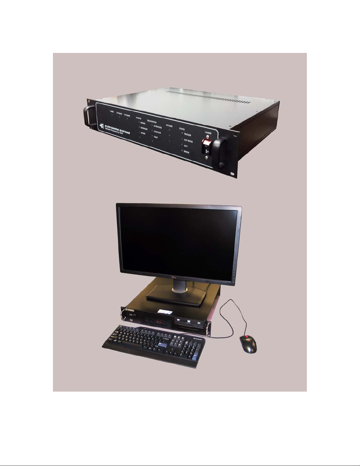
Transceiver and Processing Unit (TPU). The TPU is shown in Figure 1-1.
The main power switch is located on the lower right corner of the front panel.
The TPU is rack mountable in a standard 48.26 cm (19 inch) rack and contains
electronics for receiving sonar data, downlink multiplexing of control signals
to the Sonar Head Unit, and uplink demultiplexing of sonar and auxiliary
sensor signals.
SonarPro Workstation. The SonarPro Workstation is shown in Figure 1-1.
Most operator functions are accomplished through the use of the SonarPro
Workstation which supports the PC based Windows operating system and runs
SonarPro. SonarPro provides the operator interface to the HydroChart 5000
Sonar System. SonarPro is a comprehensive software package developed to
support survey planning; data visualization and quality control; target
management and data recording; and playback. SonarPro also performs the
side scan and bathymetry data processing. Data can be logged in SDF, GSF or
XYZ format. These formats are supported by most third party post-processing
software applications. In addition to processed data, raw stave data can be
logged together with all motion, navigation, and heading and sound velocity
data. This permits reprocessing of both side scan and bathymetry data in a
post-processing environment. For more information on the computer, refer to
the manufacturer's manual.
Surface Equipment 1-3
1.4 Subsurface Equipment
The subsurface equipment comprises the Sonar Head Unit, as shown in Figure 1-2
on page 1-5, and a deck cable. In addition, an optional sound velocity sensor can
be included for measurement of surface sound velocity.
Sonar Head Unit. The Sonar Head Unit is shown in Figure 1-2. It consists of
the sonar electronics, the transducers, the sonar altimeter, a support frame,
interconnect cables, and fairings. An optional sound velocity sensor and cable
can also be installed in the Sonar Head Unit.
Deck cable. The deck cable is a complete assembly consisting of a coaxial
cable in a Kevlar reinforced light weight Polyurethane jacket.
Page 22
1-4 CHAPTER 1 Overview
SonarPro Workstation
Transceiver and Processing Unit (TPU)
Figure 1-1: HydroChart 5000 Sonar System Topside System Main Components
HydroChart 5000 Sonar Operations and Maintenance Manual P/N 11210080, Rev. 02
Page 23
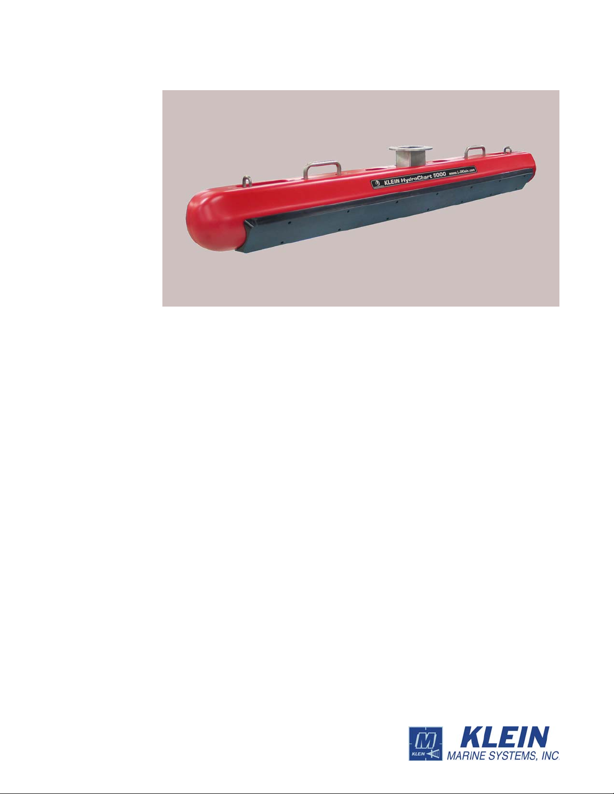
Technical Description 1-5
Figure 1-2: HydroChart 5000 Sonar System Sonar Head Unit
1.5 Technical Description
The HydroChart 5000 Sonar System is a multiple swath forming, frequency
modulated (FM) chirp side looking sonar that provides high speed, high resolution,
extended range imagery and bathymetry. The two primary drawbacks of
conventional side-looking sonars, along-track resolution and towing speed
limitation, have been addressed by simultaneously forming multiple dynamically
focused beams per side, per ping. This allows greater side scan survey speeds
without the usual loss of bottom coverage while maintaining high resolution. In
addition, the formed swaths are focused dynamically with across-track range,
thereby offering an inherently improved along-track resolution over unfocused
systems. The interferometric bathymetry (also referred to as Phase Differencing)
component of the HydroChart 5000 Sonar System is not a multibeam sonar and
requires that speed and range settings be considered when operating the system for
100% bottom coverage.
1.5.1 Sonar Head Unit
The Sonar Head Unit consists of the sonar arrays together with the sonar
electronics in a lightweight frame assembly. The sonar electronics, which is
contained inside a waterproof housing, includes transmitters, receivers and digital
circuits that combine time-synchronized complex stave samples, ping trigger
timing and optional time-synchronized motion data from the vessel’s sensors. An
altimeter is included, and the system accommodates an optional sound velocity
sensor or a CTD. For hull mount configurations, the electronics bottle is located
inside the vessel’s hull, and an optional transducer mounting bracket is required.
The two transducer arrays are each composed of 12 piezoelectric ceramic
Page 24

1-6 CHAPTER 1 Overview
sub-arrays and three bathymetry sub-arrays that operate as receive elements. There
is also a separate transmit line array included that projects acoustic energy to the
seabed.
NOTE The transducers are side specific and are not interchangeable.
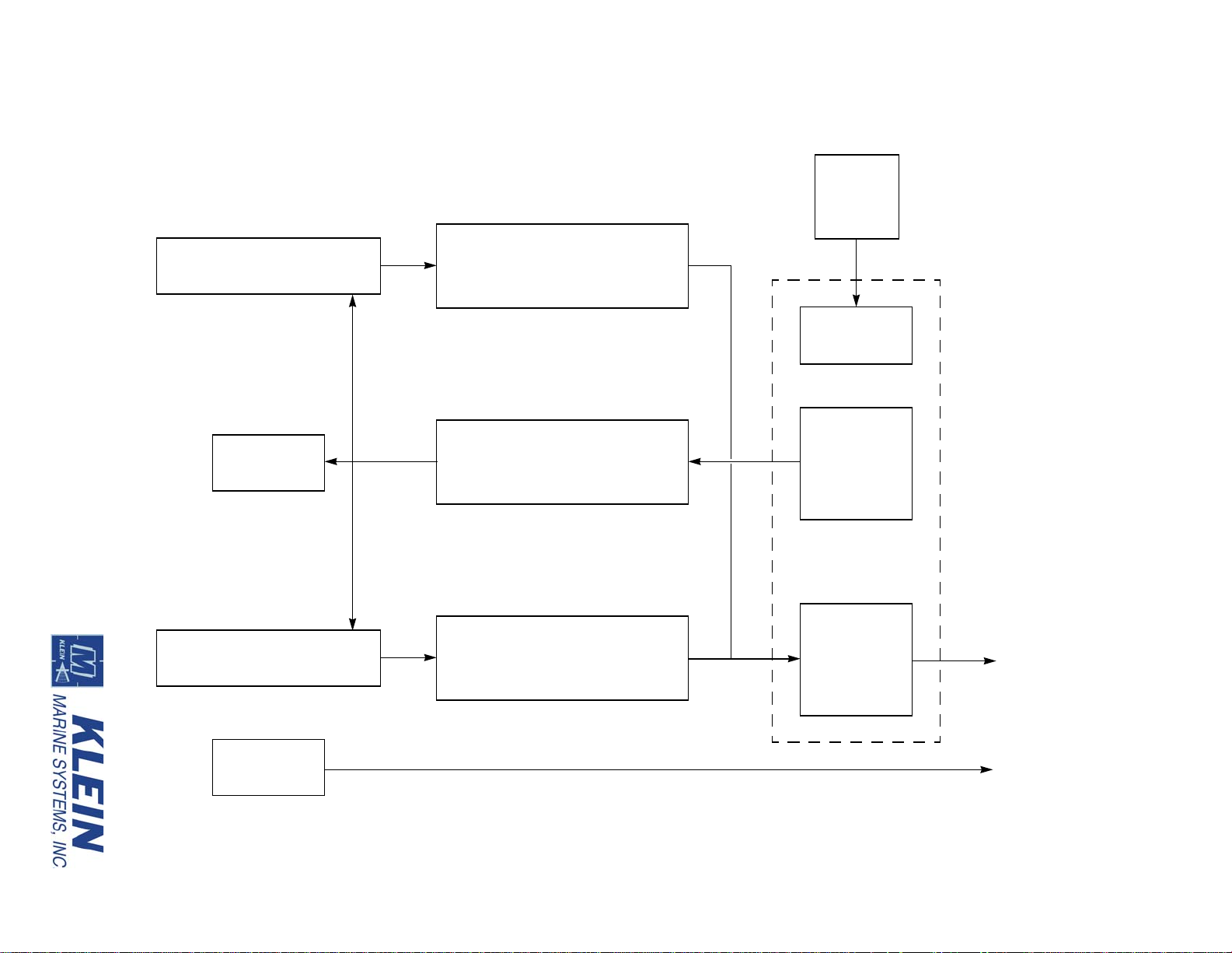
The Sonar Head Unit sonar electronics includes a T ransmitter board, two Receiver
boards and a Multiplexer board. A block diagram of the Sonar Head Unit is shown
in Figure 1-3.
Transmitter board. The Transmitter board produces a transmit pulse, at the
start of a swath, that ensonifies the sea floor over a defined footprint. The
Transmitter board is composed of two individual transmitting channels, one
connected to the port array and the other connected to the starboard array. The
transmitters operate at a center frequency of 455 kHz and support both CW and
chirp waveform transmission. The Transmitter board also contains transmit
and receive circuitry for the altimeter.
Receiver boards. The Receiver boards process the backscatter information by
applying fixed gain, time varied gain (TVG) and frequency filtering to the
input voltage signals received from the individual sub-arrays in the transducer
arrays. There are two Receiver boards, one for the port array and one for the
starboard array. Each of the receiver channels is bandpass filtered with tightly
matched filters providing a -3dB bandwidth of 20 kHz, centered at 455 kHz.
The filtered signal is then output to the Multiplexer board for sampling.
Multiplexer board. The Multiplexer board digitizes the signals from each of
the transducer sub-array channels along with the signals from the sensors,
encodes the data, and transmits a high baud rate digital data stream to the TPU
over the deck cable. The Multiplexer board also receives the trigger signal and
command messages which instruct the T ransmitter board to fire the arrays and
configure aspects of the sonar operation. In addition, the Multiplexer board
functions as a motherboard for the other boards providing the connections and
distributing power . The Multiplexer board uses a proprietary sampling scheme
that preserves the phase of the individual channel signals, but only requires a
single A/D converter, thereby reducing cost and power consumption while
eliminating the phase mismatch between converters of alternate dual converter
schemes. The output of the A/D is input to the data encoder and converted to
serial data for subsequent transmission over the deck cable. A full duplex
hybrid allows data transmission up the cable while simultaneously receiving
the FSK trigger signals and power. The downlink signals are input to FSK
demodulators, and the baseband outputs are routed to the Transmitter board,
indicating when to fire the main array, and to a micro controller that handles
the sonar configuration.
HydroChart 5000 Sonar Operations and Maintenance Manual P/N 11210080, Rev. 02
Page 25
Port Side Scan Transducer Array
Stbd Side Scan Transducer Array
Altimeter
Sound Velocity
Sensor
(Optional)
Receiver (port)
Transmitter
Receiver (starboard)
Power
Interface
Power
Supply
Transmitter
Control and
TVG Interface
Multiplexer,
ADC and
Telemetry
Deck Cable
to TPU
SVP Cable
Multiplexer
to TPU
Figure 1-3: HydroChart 5000 Sonar System Sonar Head Unit Block Diagram
Technical Description 1-7
Page 26

1-8 CHAPTER 1 Overview
A deck cable connector connects the Sonar Head Unit sonar electronics to the
TPU. The deck cable connector is shown in Figure 1-4, and the pinouts are shown
in Table 1-1. Only two pins are used.
Figure 1-4: Deck Cable Connector—at Sonar Head Unit
Table 1-1: Deck Cable Connector—Sonar Head Unit
PIN NO. LABEL FUNCTION
1
2 Shield Power and data return
Power/Data +200 VDC power and multiplexed data
1.5.2 TPU
A block diagram depicting the functional relationships of all of the printed circuit
boards in the TPU electronics is shown in Figure 1-5. These boards are located in
the TPU electronics chassis as shown in Figure 1-6 on page 1-10. The printed
circuit boards, along with their corresponding part numbers, are the following:
• Demultiplexer board 14105785
• CPU board 14105873
• 200V Power Supply board 11700098
• 200V Power Filter board 14104980
• Telemetry Interface board 14105841
• 12V Power Supply board 11700092
• 12V Power Filter board 14105397
• LED board 14105464
HydroChart 5000 Sonar Operations and Maintenance Manual P/N 11210080, Rev. 02
Page 27

Figure 1-5: HydroChart 5000 Sonar System TPU Electronics Block Diagram
Technical Description 1-9
Page 28

HydroChart 5000 Sonar Operations and Maintenance Manual P/N 11210080, Rev. 02
Topside Telemetry
board
CPU board
Demultiplexer
200V
Power Supply
200V Power
Filter board
12V Power
Filter board
12V Power
Supply board
LED board
board
board
1-10 CHAPTER 1 Overview
Figure 1-6: HydroChart 5000 Sonar System TPU Electronics Chassis
Page 29

Technical Description 1-11
Assembled into a single rack mountable 2U enclosure, the TPU connects to the
Sonar Head Unit. It also connects to the SonarPro Workstation over an Ethernet
connection and to customer supplied equipment, such as a GPS and an acoustic
positioning system.
Demultiplexer board. The Demultiplexer board demultiplexes the uplink
sonar and sensor data from the Sonar Head Unit and outputs FSK downlink
commands along with 200 VDC power to the Sonar Head Unit while providing
all of the external input and output signal and data connections for the TPU. It
also provides the required recovery of signal and clock, detects trigger inputs
and 1-PPS signals, generates the trigger outputs, inputs NMEA 0183 data, time
stamps all of the data, and outputs the data to the SonarPro Workstation over
the Ethernet connection. 200 VDC power is input to the Demultiplexer board
from the 200V Power Filter board, and 12 VDC power is input from the 12V
Power Filter board. The Demultiplexer board also provides front panel
indicator outputs which drive the front panel LEDs on the LED board.
CPU board. The CPU board functions as the command and data interface
between the SonarPro Workstation and the Sonar Head Unit. It executes a
real-time data server which outputs sonar and sensor data to and receives
commands from an external client, such as SonarPro.
200V Power Supply board. The 200V Power Supply board provides
200 VDC which is output to the Sonar Head Unit to power it.
200V Power Filter board. The 200V Power Filter board provides noise
filtering of the 200 VDC power for transmission to the Sonar Head Unit over
the coaxial tow cable. The filtered 200 VDC power is output to the
Demultiplexer board where it is combined with the FSK control signals and
output to the Sonar Head Unit.
Telemetry Interface board. The T e lemetry Interface board provides the cable
interface for the TPU. Specifically, the Tele metry Inter face board perf orms the
following functions:
• Separates the uplink data signals, the downlink command signals and the
Sonar Head Unit power.
• Acquires sonar and sensor data and reformats the data as required for the
Demultiplexer board.
• Generates command and timing signals for the Sonar Head Unit.
• Matches the time references at the Sonar Head Unit and the TPU.
12V Power Supply board. The 12V Power Supply board inputs 100–125 or
200–250 VAC and outputs 12 VDC to the 12V Power Filter board.
Page 30

1-12 CHAPTER 1 Overview
12V Power Filter board. The 12V Power Filter board provides noise filtering
of the 12V power supply for the Demultiplexer board.
LED board. The LED board contains all of the front panel LED indicators. It
mounts directly to the back of the front panel and connects to the
Demultiplexer board over a single cable.
HydroChart 5000 Sonar Operations and Maintenance Manual P/N 11210080, Rev. 02
Page 31

CHAPTER 2: SPECIFICATIONS
This chapter includes the physical and performance specifications for the main
components of the HydroChart 5000 Sonar System. The specifications are typical
and subject to change without notice.
2.1 Sonar System
Deployment method: Over the side or hull mount
Sonar channels: Multiple side scan sonar channels and
6 sensor/auxiliary channels
Sonar frequency: 500 kHz nominal (455 kHz actual)
Pulse length: 16 ms maximum (chirp)
2-1
Sonar data processing: Uncorrected
Range scale: 50, 75, 100, and 150 m; 50 and 75 m are
high resolution
Maximum range: Up to 150 m per side
Number of beams (side scan): 10 (5 per side)
Swath width (side scan): 500 m (250 m per side)
Maximum swath (bathymetry): 10–12 times water depth
Resolution along-track
(bathymetry):
Resolution across-track
(bathymetry):
Resolution along-track
(side scan):
0.4
0.5 m
cm @ 38 m
20 cm @ 75 m
36 cm @ 150 m
50 cm @ 250 m
Resolution across-track
(side scan):
3.75 cm
Depth limit: Up to 50 m
Operating temperature: -10–35C (14–95F)
Page 32

2-2 CHAPTER 2 Specifications
2.2 Topside System
The main topside components of the HydroChart 5000 Sonar System are the
Transceiver and Processing Unit (TPU) and the SonarPro Workstation.
2.2.1 System Power Requirements
The system power requirements are 100–125 or 200–250 VAC, 50–60 Hz at
100 watts for the TPU and the Sonar Head Unit together.
2.2.2 TPU
Size: 8.9 cm (3.5 in.) H
Weight: 7.6 kg (17 lb)
Chassis type: 2U, 19-inch rack mount
48.3 cm (19.0 in.) W
35.6 cm (14.0 in.) D
2.2.3 SonarPro Workstation
Size: 8.9 cm (3.5 in.) H
48.3 cm (19.0 in.) W
43.2 cm (17.0 in.) D
Weight: 22.8 kg (50 lb)
Chassis type: 2U, 19-inch rack mount
CPU: Intel Pentium Dual Core
Memory: 8 GB
Storage: SATA hard drive
DVDRW optical drive
I/O ports: (2) Ethernet 10/100/1000baseT
(6) USB 2.0
(2) RS-232
(1) VGA
(1) DVI (dual display support)
Operating system: Windows 7, 64 bit
Monitor: 21.5-inch diagonal
2560 x 1440 resolution
16:9 aspect ratio
Operator I/O: Keyboard and mouse
HydroChart 5000 Sonar Operations and Maintenance Manual P/N 11210080, Rev. 02
Page 33

2.3 Sonar Head Unit
2.3.1 General
Electronics boards: Modular
2.3.2 Transducers
Type: Proprietary line array
Vertical beam angle: 40°
Depth limit: 200 m
2.3.3 Transmitter
Type: CW and chirp
Pulse width: 50 µs, 2 ms, 4 ms, 8 ms, 16 ms, and chirp
Sonar Head Unit 2-3
2.3.4 Receiver
Type: High gain, tuned preamplifier with TVG
Noise figure: 1 dB nominal
TVG range: 80 dB
2.3.5 A/D Converter
Type: Pipeline
Resolution: 14 bits
Quantization: Linear
Sample rate: Proprietary
2.3.6 Multiplexer
Modulation format: Pulse code modulation (PCM)
Multiplexing format: Time division multiplexing (TDM)
Number of channels: 32
Data rate: 29.12 Mbaud
Data format: NRZ
Bit error rate: Better than 1x10
-8
(before correction)
Page 34

2-4 CHAPTER 2 Specifications
2.3.7 Power
Input power: Powered from the TPU; no additional
2.3.8 Physical Characteristics
Body material: Stainless steel frame, plastic fairings,
Size: 162.8 cm (64.1 in.) long
Weight in air: 29.5 kg (65 lb)
Weight in water: 9.1 kg (20 lb)
power required
pressure case, and end cap
19.8 cm (7.8 in.) wide
15.5 cm (6.1) high (w/o mtg flange)
23.1 cm (9.1) high (w/ mtg flange)
2.4 SonarPro Workstation
For specifications on the SonarPro Workstation, refer to the manufacturer's
manual.
2.5 Deck Cable
Type: Polyurethane jacketed coaxial, Kevlar
Conductors: Coaxial copper
Diameter (OD): 1.16 cm (0.455 in.)
Breaking strength: 2270 kg (5000 lb)
Working load: 454 kg (1000 lb)
Operational length: 100 m maximum
Voltage rating: 600 VDC
Termination: Subconn underwater pigtail with locking
reinforced
sleeve
HydroChart 5000 Sonar Operations and Maintenance Manual P/N 11210080, Rev. 02
Page 35

2.6 Options
The HydroChart 5000 Sonar System design provides the configuration flexibility
to meet your specific needs. The highly modular design of the equipment makes
this possible. This section provides information on the available optional
capabilities of the System.
2.6.1 Sound Velocity Sensor
The Sonar Head Unit can accommodate several third party sound velocity sensors.
This data is recorded along with the sonar data and can be used for surface sound
velocity measurements for post processing corrections.
2.6.2 Motion Reference Unit
The HydroChart 5000 Sonar System can interface with a variety of third party
motion reference units for correction and subsequent processing of bathymetric
data. Both Ethernet and high speed serial interfaces are supported.
Options 2-5
Page 36

Page 37

CHAPTER 3: PREPARATION FOR
DEPLOYMENT
This chapter provides instructions for unpacking and preparing the HydroChart
5000 Sonar System for deployment, including detailed instructions on the
following:
TPU and SonarPro Workstation setup. Guidelines for installing the TPU
and the SonarPro Workstation to optimize performance and equipment
lifetime.
Power and ground requirements. Power and ground requirements to
protect against over and under voltage and transient spikes.
Sonar Head Unit installation. How to install the Sonar Head Unit.
3-1
Connect the surface equipment. How to connect all of the surface
equipment, including an optional motion reference unit and a sound velocity
sensor.
Predeployment test. How to perform a predeployment test to verify that the
system is operational.
System calibration. Information on how to perform a patch test to account
for residual biases in the system installation.
3.1 Unpacking and Inspection
The HydroChart 5000 Sonar System is shipped in multiple shipping containers.
Before unpacking the containers, carefully inspect them for damage. If any
damage is found, immediately contact Klein Marine Systems, Inc. or your KMS
sales representative and report the damage to the freight carrier. Do not install or
operate any equipment that appears to be damaged.
3.1.1 Unpacking the TPU
Remove the TPU from the shipping container and set it on a sturdy, flat surface.
Inspect the TPU for signs of damage. If there is any damage or if any items are
missing, immediately contact Klein Marine Systems, Inc. or your KMS sales
representative. Record the serial number of the TPU; it can be found on a sticker
on the rear panel.
Page 38

3-2 CHAPTER 3 Preparation for Deployment
3.1.2 Unpacking the SonarPro Workstation
Remove the SonarPro Workstation from the shipping container, and set it on a
sturdy , flat surface. Inspect the So narPro Workstation for signs of damage. If there
is any damage or if any items are missing, immediately contact Klein Marine
Systems, Inc. or your KMS sales representative. Record the serial numbers of the
computer modules.
3.1.3 Unpacking the Sonar Head Unit and Deck Cable
The Sonar Head Unit and the deck cable are shipped in a reusable crate. Open the
crate and inspect the Sonar Head Unit for damage. If there is any damage or if any
items are missing, immediately contact Klein Marine Systems, Inc. or your KMS
sales representative. Record the serial number of the Sonar Head Unit. The serial
number can be found on the aft end of Sonar Head Unit mounting flange opposite
the FWD label.
3.2 Locating the Topside System Components
The TPU and the SonarPro Workstation should be located in an area that is
protected from weather and spray and where the temperatures are consistently
between 0°C and 35°C (32°F and 95°F). The location should also be near the
Sonar Head Unit or be adequately equipped with devices for communicating with
launch personnel. If separately mounting components in a 19-inch rack, ensure
that the rack is properly secured and that there is ample room behind it for
connecting the cables. A thick layer of foam should also be placed under the rack
for shock isolation, and the back of the rack should be left open for proper air flow .
Support the units inside the rack using appropriate mounting brackets, shelves or
slides as needed and secure the front panels to the front of the rack where possible
using standard 19-inch rack front panel mounting hardware.
3.3 Power Requirements
The TPU and the SonarPro Workstation require 100–125 or 200–250 VAC,
50–60 Hz power to operate. The HydroChart 5000 Sonar System is designed to
protect against over and under voltage and transient spikes. However, it is always
best to check the power source carefully using a voltmeter or oscilloscope before
operating the equipment.
CAUTION Application of improper AC power may damage the
HydroChart 5000 Sonar System. Do not turn the equipment on until the
supply voltage and frequency have been checked.
HydroChart 5000 Sonar Operations and Maintenance Manual P/N 11210080, Rev. 02
Page 39
Sonar Head Unit Installation 3-3
Since a variety of power connectors are in use throughout the world, it may be
necessary to use an adapter or to cut off the US-type plug on the AC power cable
and re-terminate it with a new plug. Should this modification be required, the
wires should be connected in accordance with Table 3-1.
Table 3-1: TPU Power Cable Wiring
COLOR FUNCTION
Green Ground (earth)
Blue or white Neutral
Brown or black Hot
3.3.1 Grounding
It is important that the HydroChart 5000 Sonar System be well grounded to
minimize potential hazards to the operator and electrical interference from other
equipment. A good ground for the system is a low impedance, well conducted path
to sea water. Always check the quality of the electrical ground by verifying that the
AC power source ground has no voltage potential with respect to the vessel hull.
3.3.2 TPU and SonarPro Workstation Circuit Breakers
The main AC power input line is protected by a switch/circuit breaker in both the
TPU and the SonarPro Workstation. The one on the TPU is located on the front
panel on the far right as shown in Figure 3-6 on page 3-12. The one on the
SonarPro Workstation is located on the pack panel just to the right of the AC
INPUT connector as shown in Figure 3-5 on page 3-9. To reset a switch/circuit
breaker, switch it to ON.
3.4 Sonar Head Unit Installation
When installing the Sonar Head Unit, lightly grease the male pins of the
waterproof connectors before connecting them. The silicone grease serves an
important lubricating and corrosion protection function. Use a high quality,
nonconducting grease such as Dow Corning DC-4. Before connecting the deck
cable, make a general inspection of the Sonar Head Unit. Check that the fasteners
holding the Sonar Head Unit to the mounting platform are tight. Check that all
cables running from the Sonar Head Unit are secured. A safety cable should also
be attached to the Sonar Head Unit in the event that it breaks free.
Page 40

3-4 CHAPTER 3 Preparation for Deployment
Four 0.4-inch diameter holes
on a 5-inch bolt circle
6-inch diameter
mounting flange
CAUTION Always avoid putting excessive silicon grease on the Subcon
male pins. Apply a light coat of gr ease, and never put gr ease into the female
connectors.
NOTE When installing the Sonar Head Unit, r efer to Drawing 14605080 in
APPENDIX B: “Drawings.” for the outline dimensions of the Sonar Head
Unit.
The Sonar Head Unit is mounted to the survey vessel by attaching the mounting
flange at the top of Sonar Head Unit to a standard 6-inch pipe flange or other
mounting surface. A bolt pattern is provided on the mounting flange as shown in
Figure 3-1. For a typical, pole mount type over-the-side installation, this design is
well suited for attaching to the base of a pipe.
FWD on the neck of the mounting flange as shown in Figure 3-2. An arrow label is
also included.
Figure 3-2: FWD and Arrow Labels on the Sonar Head Unit Mounting Flange
Figure 3-1: Sonar Head Unit Mounting Flange
NOTE When attaching the Sonar Head Unit to the mounting surface, it is
important to ensure that the assembly is mounted correctly in the fore/aft
direction. The end of the Sonar Head Unit that faces the bow is labeled
HydroChart 5000 Sonar Operations and Maintenance Manual P/N 11210080, Rev. 02
Page 41

Sonar Head Unit Installation 3-5
Handles (2)
Eye rings (2)
To install the Sonar Head Unit:
1. Align the bolt hole patterns and secure the mounting flange to the pipe flange
using stainless steel hardware. Be sure to maintain the long axis of the Sonar
Head Unit parallel to the keel at all times. However, offsets can be corrected
with a patch test as described in “Bathymetric System Calibration and Patch
Test” on page 3-15.
2. If your installation permits, it is suggested that you attach straps to the eye rings
or handles on the fore and aft portions of th e Sonar Head Unit an d secure them to
the bow and stern of the survey vessel to minimize any induced body motion. The
eye rings and handles are shown in Figure 3-3.
Figure 3-3: Sonar Head Unit Eye Rings and Handles
WARNING In all of the remaining steps, be sure that the power is turned
off and the TPU power cable is disconnected from the power source.
Failure to follow this practice may result in personal injury or damage to
the Sonar Head Unit or to the TPU electronics, or to both.
SHOCK HAZARD Do not connect or disconnect the deck cable from the
Sonar Head Unit or the TPU when the power is on. Failure to follow this
practice may result in personal injury and will damage the Sonar Head
Unit or the TPU electronics, or both.
3. Remove the dummy plug from the connector on the end of the Sonar Head Unit
jumper cable, and then apply a thin film of silicone grease to the pins of the
connector. Do not over grease. Align this connector with the female connector of
the deck cable and press the connectors firmly together. If necessary, use a slight
side to side rocking motion while pressing on the connectors, but do not bend the
pins. When properly inserted there should be no gap between the surfaces of the
two connectors. Screw the locking sleeves together to complete the connection.
4. Secure the deck cable to the Sonar Head Unit using tie-wraps.
Page 42

3-6 CHAPTER 3 Preparation for Deployment
5. If an optional sound velocity sensor is included, there will also be a cable
assembly included whose wet end should have been factory connected to the
sensor. Verify that this connector is properly seated and that the locking sleeves
are secure. Use tie-wraps to secure the cable to the Sonar Head Unit.
3.5 Motion Reference Unit Installation
The HydroChart 5000 Sonar System is capable of interfacing with several
industry-standard motion reference systems. These devices are critical to
measuring vehicle motion and correcting for its effect on the bathymetric data.
Connection and configuration of these devices is documented in the "HydroChart
5000 Motion Sensor Installation Guide" (P/N 11260086).
3.6 Topside System Connections
All of the topside system components connect together using the supplied cables.
User supplied cables are required for connecting to a GPS and to other equipment.
3.6.1 TPU Connections
All the connections to the TPU are made to connectors on the back panel which is
shown in Figure 3-4.The TPU connectors are the following:
LAN: RJ-45 connector that connects to the ETHERNET
connector on the SonarPro Workstation.
COM A (Debug): DB9 male RS-232 serial port connector that is for
factory use only.
COM B (Sound Velocity): DB9 male RS-232 serial port connector that inputs
sound velocity.
COM C (Motion
Reference Unit):
NAV: DB9 male RS-232 serial port connector that
EXT TRIG IN: Not supported for this system.
T/F TRIG: BNC connector that connects to an external sonar
DB9 male RS-232 serial port connector that inputs
motion reference unit data.
connects to a shipboard navigation system and
inputs NMEA 0183 message sentence formats.
system and is used to trigger the sonar of that system
at the start of each ping cycle. Provides a TTL
compatible, 100-µs wide output pulse.
HydroChart 5000 Sonar Operations and Maintenance Manual P/N 11210080, Rev. 02
Page 43
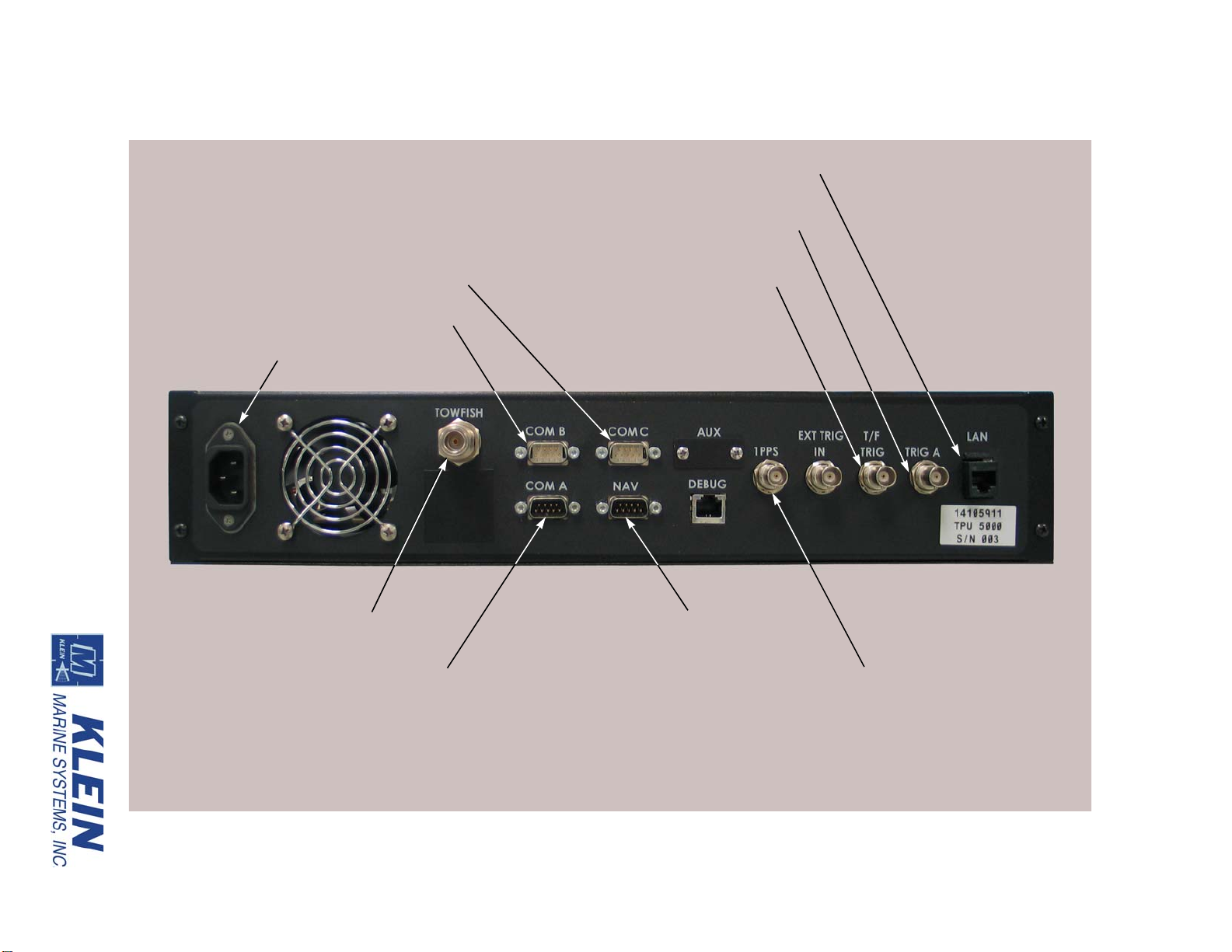
TOWFISH connector
NOTE: Connectors that are not
called out are not used or are
for factory use only.
NAV connector
AC INPUT connector
1 PPS connector
T/F TRIG connector
TRIG A connector
LAN connector
COM A (Debug) connector
COM B (Sound Velocity) connector
COM C (Motion Reference Unit) connector
Topside System Connections 3-7
Figure 3-4: TPU Back Panel
Page 44

3-8 CHAPTER 3 Preparation for Deployment
TRIG A:
BNC connector that connects to an ultra short
baseline navigation system (USBL). Provides a TTL
compatible, 100-µs wide output pulse with each
trigger of the optional responder.
1 PPS: BNC connector that connects a GPS and is used to
input 1 PPS (one pulse per second) signals.
TOWFISH: Type N coaxial connector that connects to the Sonar
Head Unit.
AC INPUT: IEC type connector that connects to the AC power
source.
3.6.2 SonarPro Workstation Connections
All the connections to the SonarPro Workstation are made to connectors on the
back panel which is shown in Figure 3-5.
The SonarPro Workstation connectors are the following:
USB: USB connectors (4, plus 2 on the front panel). Any
two connect to the keyboard and the mouse. The
front panel USB connectors are shown in Figure 3-7
on page 3-14.
DVI: DVI connector that connects to the monitor.
ETHERNET: RJ-45 connectors (2). Any one connects to the LAN
connector on the TPU.
AC INPUT: IEC type AC input connector that connects to the
AC power source.
3.7 Connecting the Topside System Components
The following cables are required to connect the TPU and the SonarPro
Workstation:
• Ethernet cable
• AC power cords (2)
• Deck cable
WARNING Before connecting the topside system components, verify that
the TPU is turned off and that its power cord is disconnected. Failure to
follow this practice may result in personal injury or damage to the Sonar
Head Unit or to the TPU electronics, or to both. For the location of the power
switches, refer to “Topside System Controls and Indicators” on page 3-11.
HydroChart 5000 Sonar Operations and Maintenance Manual P/N 11210080, Rev. 02
Page 45
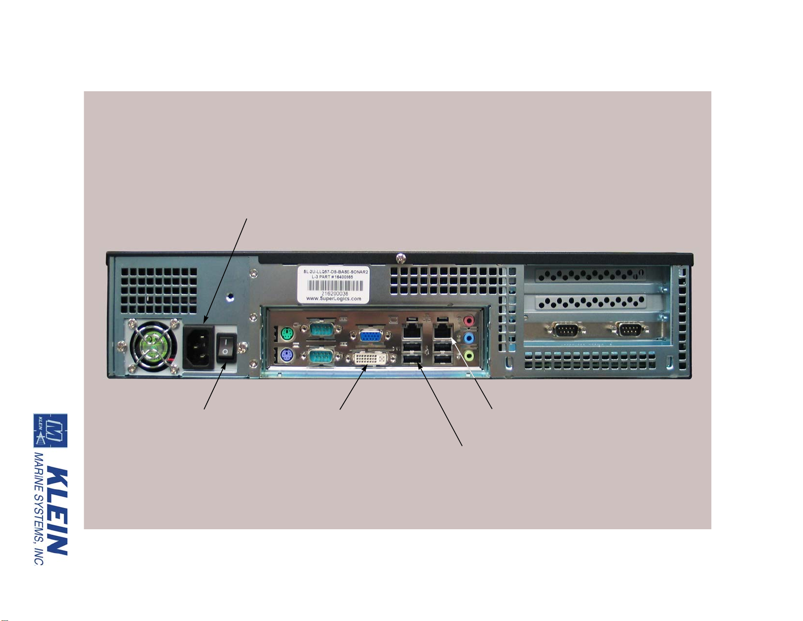
ON/OFF switch
AC INPUT connector
ETHERNET connector (2)
USB connector (4)
NOTE: Connectors that are not
called out are not used or are
available for optional use.
DVI connector
and circuit breaker
Connecting the Topside System Components 3-9
Figure 3-5: SonarPro Workstation Back Panel
Page 46

3-10 CHAPTER 3 Preparation for Deployment
To connect the TPU and the SonarPro Workstation:
1. Connect the Ethernet cable to the LAN connector on the TPU and to either
one of the two the ETHERNET connectors on the SonarPro Workstation.
2. Connect the monitor to the DVI connector on the SonarPro Workstation and
connect the monitor power supply to the AC power source.
3. Connect the keyboard and the mouse to any two of the six USB connectors on
the SonarPro Workstation.
4. Connect a GPS to the NAV connector on the TPU. A user supplied RS-232
serial cable is required where one end is terminated with a DB9 female
connector and the other end is as required by the navigation system.
5. Verify that the GPS is outputting NMEA-0183 formatted data strings at
4800 baud, no parity , 8 data bits, and 1 stop bit. In addition, the GPS should be
outputting the following messages:
• GLL or GGA
•VTG
• RMC (optional)
NOTE If 4800 baud is not available from the GPS, contact KMS customer
service for instructions on how to reconfigure the system to accept a
different baud rate. Refer to “Customer Service” on page xvii for
information on how to contact KMS customer service.
6. Connect the deck cable to the TOWFISH connector on the TPU.
7. Connect an AC power cable to the AC INPUT connectors on the TPU and the
SonarPro Workstation and to the AC power source.
The following connections are optional:
8. Connect the 1 PPS connector on the TPU to the 1 PPS output of the shipboard
GPS. A user supplied BNC-to-BNC cable is required.
9. Connect the T/F TRIG connector on the TPU to the trigger input of an
external sonar system. A user supplied BNC-to-BNC cable is required.
10. Connect the TRIG A connector on the TPU to the trigger input of a USBL
system. A user supplied BNC-to-BNC cable is required.
11. Connect the COM B (Sound Velocity) connector to the sound velocity sensor
if installed on the Sonar Head Unit.
12. Connect the COM C (Motion Reference Unit) connector to the motion
reference unit if available.
HydroChart 5000 Sonar Operations and Maintenance Manual P/N 11210080, Rev. 02
Page 47

Topside System Controls and Indicators 3-11
3.8 Topside System Controls and Indicators
The TPU and the SonarPro Workstation include controls and indicators on the
front panels. The SonarPro Workstation also has its power switch on the back
panel.
3.8.1 TPU Controls and Indicators
All of the TPU controls and indicators are on the TPU front panel which is shown
in Figure 3-6.
The TPU controls and indicators are the following:
POWER switch: Rocker switch/circuit breaker that turns the TPU on
or off and provides AC input current protection.
Should the breaker trip, the switch/circuit breaker
will switch to the OFF position. To reset it, switch it
to the ON position.
POWER: Green LED that is on when the TPU is powered.
SYS READY: Green LED that will flash while the TPU and the
Sonar Head Unit are powering up and then remain
on when the TPU is ready to link with SonarPro on
the SonarPro Workstation.
T/F POWER: Blue LED that is on when power is being output to
the Sonar Head Unit.
TOWFISH AWAKE: Green LED that is on when the Sonar Head Unit is
powered and is acquiring data.
TOWFISH DOWNLINK: Green LED that is on when commands are being
transfered from the TPU to the Sonar Head Unit.
TOWFISH UPLINK: Green LED that is on when data are being transfered
from the Sonar Head Unit to the TPU.
STATUS TRIGGER: Yellow LED that flashes when the sonar on the
Sonar Head Unit transmits.
STATUS RESPONDER: Yellow LED that flashes when a responder trigger is
sent to the Sonar Head Unit.
STATUS ERROR: Red LED that flashes if system errors are detected.
Page 48

HydroChart 5000 Sonar Operations and Maintenance Manual P/N 11210080, Rev. 02
POWER indicator
SYS READY indicator
T/F POWER indicator
TOWFISH indicators
POWER switch
STATUS indicators
NOTE: Indicators that are not
called out are not used or are
available for optional use.
3-12 CHAPTER 3 Preparation for Deployment
Figure 3-6: TPU Front Panel
Page 49

Predeployment Test 3-13
3.8.2 SonarPro Workstation Controls and Indicators
Most of the SonarPro Workstation controls and indicators are on the SonarPro
Workstation front panel which is shown is Figure 3-7. Also shown is the location
of the DVDRW optical drive.
The SonarPro Workstation controls and indicators are the following:
ON/OFF switch: Rocker switch/circuit breaker that switches AC
power to the SonarPro Workstation and provides AC
input current protection. This switch/circuit breaker ,
which is on the back panel and is shown in
Figure 3-5 on page 3-9, should be left in the ON
position. Should the breaker trip, the switch/circuit
breaker will switch to the OFF position. To reset it,
switch it to the ON position.
HARD DRIVE ACTIVITY: Green LED that flashes when the hard drive is being
accessed.
ETHERNET: Green LED that flashes when there is activity on
POWER: Blue LED that is on when the SonarPro Workstation
POWER switch: Push button switch that turns the SonarPro
RESET switch: Push button switch that resets the SonarPro
3.9 Predeployment Test
To perform the predeployment test:
1. Verify that the Sonar Head Unit has been properly set up and the system
components connected.
2. Turn on the navigation system and let it acquire its location.
3. Verify that the deck cable is connected to the Sonar Head Unit and to the TPU.
4. Turn on the SonarPro Workstation and wait for the Windows desktop to appear.
Ethernet port.
is on.
Workstation on or off.
Workstation.
5. Turn on the TPU.
The SYS READY indicator should flash. Then after approximately 1 minute,
the T/F POWER indicator should turn on, the SYS READY indicator should
stop flashing and remain on, and the STATUS TRIGGER indicator should
begin flashing at the ping rate of the sonar.
Page 50
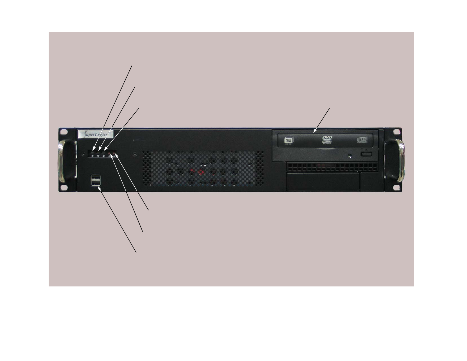
HydroChart 5000 Sonar Operations and Maintenance Manual P/N 11210080, Rev. 02
HARD DRIVE ACTIVITY indicator
POWER ON indicator DVDRW optical drive
ETHERNET indicator
RESET switch
POWER switch
USB connector (2)
3-14 CHAPTER 3 Preparation for Deployment
Figure 3-7: SonarPro Workstation Front Panel
Page 51

Bathymetric System Calibration and Patch Test 3-15
CAUTION Serious damage to the Sonar Head Unit electronics may occur
if the Sonar Head Unit is operated on deck for periods longer than fifteen
minutes. Between periods of operation, let the sonar cool for fifteen
minutes. In high temperature climates, protect the Sonar Head Unit from direct
exposure to the sun prior to and during operation.
6. Start SonarPro.
7. Verify that the Sonar Head Unit is transmitting by viewing the output pulse in the
Scan window . In addition, and if available, v erify that position, motion and sound
velocity data are being displayed in the Information window.
8. Select the 150-meter range and perform a rub test on the port and starboard
transducers by vigorously rubbing each transducer , one at a time, while ob serving
the Sonar Viewer window.
The signal amplitudes should be prominent whenever the transducers are
rubbed.
9. Exit SonarPro.
10. Turn off the SonarPro W orks tation and the TPU.
3.10 Bathymetric System Calibration and Patch Test
For new installations it is recommended that a patch test be performed to quantify
any residual biases in the installation which could affect the accuracy of the
bathymetry data. The tests use a series of reciprocal lines run at different speeds,
depths and bottom slopes as inputs to compute the following residual biases:
• Positioning/Latency error
• Pitch bias
• Yaw bias
• Roll bias
For the tests outlined below, all acquired data can be batch processed using the
Klein Batch Processing GUI application and subsequently analyzed using a
third-party application, such as Caris and Hypack. For details regarding the data
interface/conversion, see the Help file in the Klein Batch Processing GUI
application. The tests are listed in the recommended order in which they should be
processed. For example, latency should be processed before pitch, which is
followed by yaw, and then roll. This will eliminate the effects of uncorrected errors
on the other axis.
Page 52

3-16 CHAPTER 3 Preparation for Deployment
Following are a few available references containing information about the
calculation procedures for these offsets and errors:
• "Field Procedures for the Calibration of Shallow Water Multibeam
Echo Sounding Systems," Andre G odin, Canadian Hydrographic
Service, Halifax, Nova Scotia, Canada, 1996.
• "US Army Corps of Engineers, Engineer Manual EM-1110-2-1003,"
Hydrographic Surveying, Jan-02.
3.10.1 Static Position Offsets
It is necessary to first measure the static position offsets between the Sonar Head
Unit, the position sensor and the motion reference unit, relative to some reference.
These measurements will provide the necessary data for applying lever-arm
corrections to the final bathymetric solution. SonarPro provides an interface to
record these offsets in the Ship Geometry Setup dialog box such that they can be
recorded along with the sonar data to provide real time correction during data
acquisition. See the "SonarPro User Manual" (P/N 11210079) for more
information.
3.10.2 Latency Error
This test will provide a measurement of the latency error, or time, in the overall
system, which manifests itself as a position error in the processed data. It is
recommended that lines be run in the same direction and at different speeds over
an area with a prominent bathymetric feature. This will offset any effects due to
pitch bias. The greater the speed difference the more accurate the measurement.
The latency can be derived by measuring the along-track displacement of depth
measurements over the bottom feature.
3.10.3 Pitch Bias Test
Pitch bias is similar to roll bias, except that pitch error lies in the along-ship’s
fore-aft axis. This error occurs when the motion reference unit and the transducer
arrays are not pitch-aligned; that is, they are not mounted on the same fore-aft axis.
The resulting error changes the apparent location of a feature and is proportional to
water depth. In addition, along-track displacement error increases as water depth
increases. For the pitch bias test the survey vessel should run reciprocal lines on a
sloped bottom, preferably on the order of 10–20 degrees, for 200–300 meters. It
may be possible to use a channel feature instead of a long sloping bottom. Speed
for the test should be equal for both lines.
HydroChart 5000 Sonar Operations and Maintenance Manual P/N 11210080, Rev. 02
Page 53

Bathymetric System Calibration and Patch Test 3-17
3.10.4 Yaw Bias Test
For the yaw bias test the objective is to determine azimuth offset error between the
motion reference unit and the sonar arrays. For this test it is recommended that the
survey vessel run two pairs of adjacent lines on reciprocal headings over a flat
bottom with a prominent bathymetric feature, such as the edge of a ship channel.
The adjacent lines should overlap by 10–20%. In computing the azimuth offset, the
data from the reciprocal lines can be used to remove any roll offset. The parallel
lines run in a direction normal to the bottom feature can be used to compute the
azimuth offset using several measurements of the across-track displacement.
3.10.5 Roll Bias Test
This test determines the athwartship alignment error between the transducer arrays
and the motion reference unit as well as any additional roll axis bias error in the
motion reference unit. The result is a roll correction which can be used during post
processing operations. For the roll bias test you should choose a relatively flat area
of the sea bottom and run at least two reciprocal lines 200–300 meters in length at
equal speeds in both directions.
Page 54

Page 55

CHAPTER 4: EQUIPMENT MAINTENANCE
This chapter provides instructions for equipment maintenance and includes guides
for taking care of the HydroChart 5000 Sonar System on a daily, weekly, and long
term basis. In addition, instructions are provided for disassembling and
reassembling the Sonar Head Unit.
4.1 Maintenance General Comments
Equipment used at sea is subjected to severe environmental and handling
conditions. While the HydroChart 5000 Sonar System is designed to operate in
such conditions, a certain amount of routine maintenance is necessary to ensure
trouble free, long term operation.
Keep a maintenance log. This provides assistance in tracking what has or has not
been done with the system. A log is useful when tracking problems, if they do
occur, and is especially important if more than one TPU, SonarPro Workstation, or
Sonar Head Unit is used in a large survey operation. Inventory the system and
related spares and accessories carefully. Record the serial numbers of the major
components, such as the TPU, the SonarPro Workstation, and the Sonar Head Unit.
Store the shipping boxes in a safe place so they can be reused when needed. A
small amount of regular maintenance and care makes the critical difference in a
successful field operation. The following pages contain the recommended routine
checking and maintenance schedules for a daily, weekly, and long term basis.
4-1
4.2 Maintenance Checklists
4.2.1 Daily Maintenance Checklist
Perform the following maintenance steps at the end of each day’s operation:
1. Turn off the power to the TPU and to the SonarPro Workstation.
2. Verify that all cables and connectors are secure and tightened.
3. If fresh water is available, wash down the Sonar Head Unit. Cover it while not in
use to protect against salt water spray and to minimize corrosion.
Page 56

4-2 CHAPTER 4 Equipment Maintenance
4. Keep the deck cable plugged into the Sonar Head Unit, or use dummy plugs to
keep the connectors from exposure to the salt atmosphere. Remember to put a
thin film of silicone grease, such as Dow-Corning 4, on the rubber portion of the
underwater connector every time the Sonar Head Unit is disconnected. Avoid
getting too much grease on the metal pins of the connector; a very light coating is
sufficient.
5. Check that all of the screws on the Sonar Head Unit are tight.
4.2.2 Weekly Maintenance Checklist
Perform the following maintenance steps at the end of each week’s operation:
1. Turn off the power to the TPU and to the SonarPro Workstation.
2. Check all cables for abrasion and damage. If any wear spots are noticed, clean
them with fresh water, dry them, and wrap them carefully with electrical tape,
such as Scotch #88 or #33. If there is wear or fraying in any of the cables in an
area subject to high tension, repair or replace the cable.
3. Inspect and clean the system connectors.
4. Inspect the Sonar Head Unit for signs of corrosion or other damage.
5. Check the underwater connectors on the Sonar Head Unit. The contacts should be
clean and shiny . Contacts may be cleaned with a rubber pencil eraser or very fine
emery paper.
4.2.3 Long Term Maintenance Checklist
Perform the following maintenance steps at six month intervals, or more
frequently when continued long term usage is occurring.
1. Turn off the power to the TPU and to the SonarPro Workstation.
2. Thoroughly clean the TPU and cables. Clean the top and outside surfaces of the
TPU using a cloth dampened with fresh water . Use a small amount of deterg ent if
necessary. Do not let dirt and salt deposits accumulate on the TPU cabinet.
3. Replace the AC fuses in the TPU as preventive maintenance. Fuses will
sometimes fatigue after long term use or operation.
4. Check that all the connectors on the Sonar Head Unit are firmly seated. Make
sure that all the cables are free from cuts or abrasion.
5. Follow the instructions in the manufacturer's manual for any necessary cleaning
and maintenance of the
HydroChart 5000 Sonar Operations and Maintenance Manual P/N 11210080, Rev. 02
SonarPro Workstation.
Page 57

Disassembling and Reassembling the Sonar Head Unit 4-3
Figure 4-1: Removing the Phillips Head Screws
from the Top of the Fairing
Fairing
4.3 Disassembling and Reassembling the Sonar Head Unit
For troubleshooting purposes and for repair, it may be required to remove and
replace major components of the Sonar Head Unit. Instructions are provided in the
following pages for the disassembly of the Sonar Head Unit and the removal of the
sonar electronics chassis.
The following tools are recommended:
• Cordless drill
• Phillips head driver bit
• 5-mm hex key
• 4-mm hex key
• Phillips screw driver
• 7-inch, 1/2 x 13 threaded rod
4.3.1 Disassembling the Sonar Head Unit
T o disassemble the Sonar Head
Unit:
1. Turn off the TPU.
2. Disconnect the deck cable
from the Sonar Head Unit
and set it on a clean flat
surface such that the
carrying handles face up.
3. Using the cordless drill
with the Phillips head
driver bit, remove the
sixteen M6 x 12 mm
Phillips head screws that
secure the top of the fairing to the frame.
Page 58
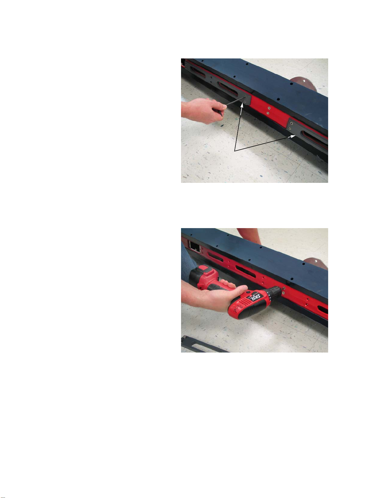
4-4 CHAPTER 4 Equipment Maintenance
Figure 4-2: Removing the Skid Plates from the
Frame
Skid plates
Figure 4-3: Removing the Phillips Head Screws
from the Bottom of the Fairing
4. Turn the Sonar Head Unit on
its side.
5. Using the 5-mm hex key,
remove the six M6 x 18 mm
socket head cap screws that
secure each of the two skid
plates to the frame, and then
remove the plates and set
them aside.
6. Remove the six M6 x 12 mm
Phillips head screws that
secure the bottom of the
fairing to the frame.
HydroChart 5000 Sonar Operations and Maintenance Manual P/N 11210080, Rev. 02
Page 59

Disassembling and Reassembling the Sonar Head Unit 4-5
Figure 4-4: Removing the Socket Head Cap
Screws that Secur e the Transducers to the Frame
Transducer (2)
Figure 4-5: Fairing Halves Separated from the
Frame
Connector
end cap
7. Using the 4-mm hex
key, remove the twelve
M5 x 20 mm socket head
cap screws that secure each
of the two transducers to
the frame.
8. Separate the two halves of
the fairing, along with the
transducers, from the frame
and set them alongside each
other such that the
connectors on the sonar
electronics housing
connector end cap can be
easily accessed.
Page 60

4-6 CHAPTER 4 Equipment Maintenance
Figure 4-6: Disconnecting the Cables from the
Sonar Electronics End Cap
Figure 4-7: Sonar Electronics Housing with all
the Cables Disconnected
Jumper cable
Altimeter cable
9. Disconnect all the cables
from the sonar electronics
housing connector end cap
and separate the transducers
from the fairings.
The sonar electronics
housing is shown with all
the cables disconnected in
Figure 4-7. The altimeter
and jumper cables should
be the only cables
remaining that are
attached to the frame,
unless an optional sound
velocity sensor is installed
for which a third cable
should be present. The
altimeter cable has a red
band attached near the
connector.
HydroChart 5000 Sonar Operations and Maintenance Manual P/N 11210080, Rev. 02
Page 61

Disassembling and Reassembling the Sonar Head Unit 4-7
Figure 4-8: Removing the Altimeter T ransducer
from the Frame
Altimeter
transducer
Figure 4-9: Removing the Socket Head Cap
Screw that Secures the Sonar Electronics
Housing
Sonar electronics
housing
Angle
bracket
10. If it is required to remove
the altimeter transducer, use
the 4-mm hex key to remove
the two M5 x 20 mm socket
head cap screws that secure
it, and then let the transducer
rest inside the frame
temporarily.
11. Using the 4-mm hex key,
remove the M6 x 12 mm
socket head cap screw that
secures the sonar
electronics housing to the
angle bracket on the frame.
Page 62
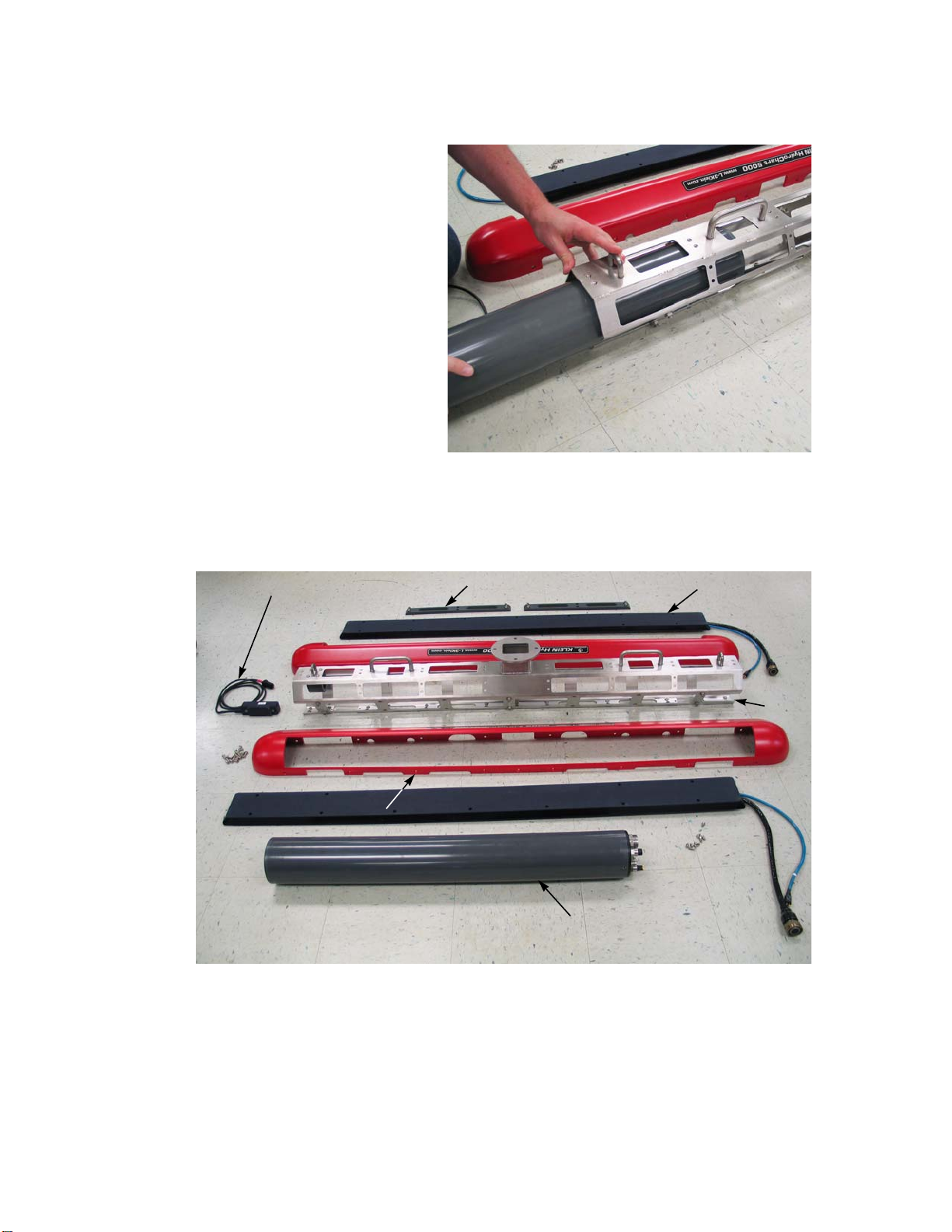
4-8 CHAPTER 4 Equipment Maintenance
Figure 4-10: Sliding the Sonar Electronics
Housing out of the Frame
Frame
Altimeter
transducer
and cable
Sonar electronics
housing
Transducer (2)
Skid plate (2)
Fairing (2 halves)
12. Slide the sonar electronics
housing completely out of
the frame.
13. Remove the jumper cable,
and if the altimeter
transducer was freed,
remove it also along with
the altimeter cable.
The Sonar Head Unit is
shown fully disassembled
in Figure 4-11. The
jumper cable is not shown.
Figure 4-11: Sonar Head Unit Fully Disassembled
HydroChart 5000 Sonar Operations and Maintenance Manual P/N 11210080, Rev. 02
Page 63
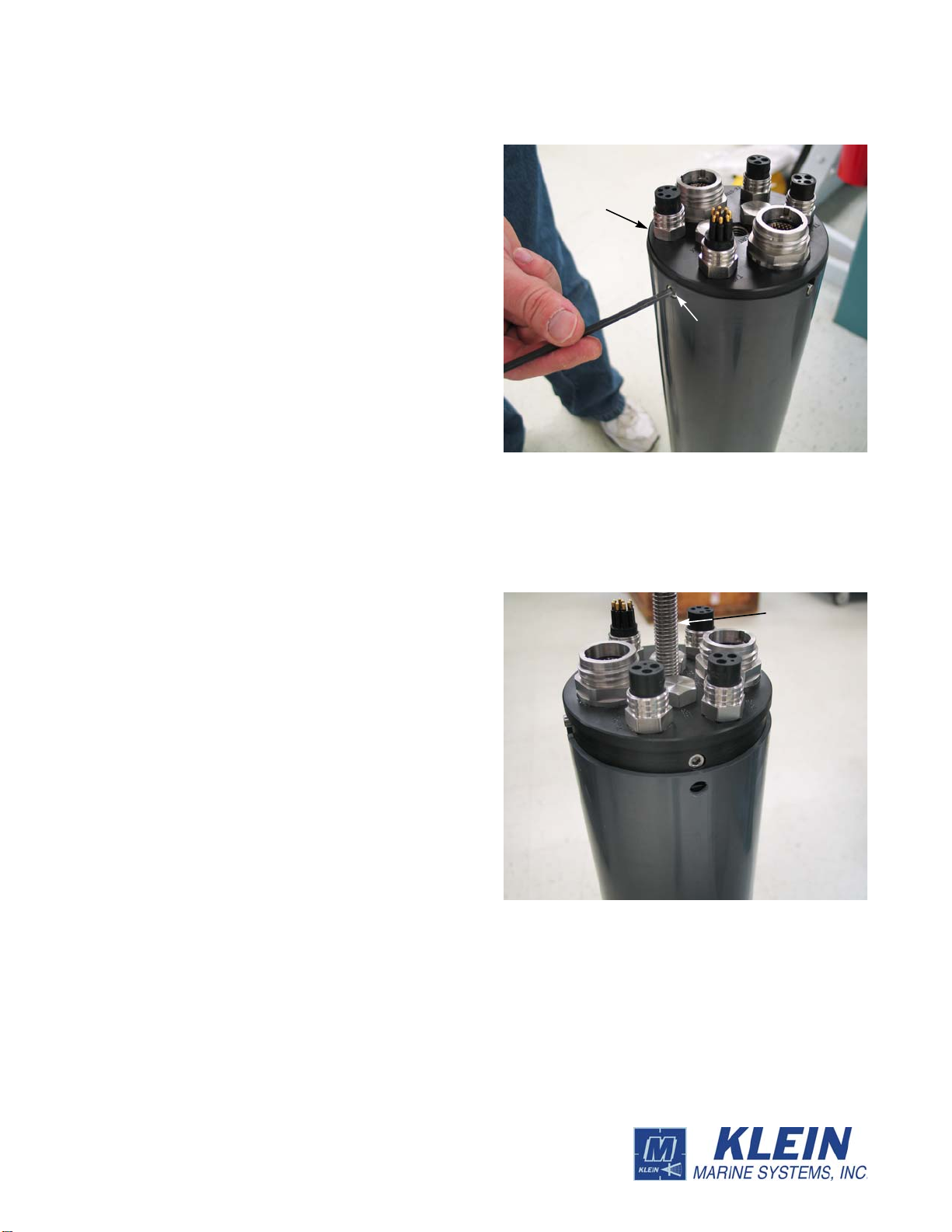
Disassembling and Reassembling the Sonar Head Unit 4-9
Figure 4-12: Tightening the Socket Head Cap
Screws in the Electronics Housing Connector
End Cap
Socket head
Connector
end cap
cap screw (2)
Figure 4-13: Inserting the 7-inch, 1/2 x 13
threaded rod into the Connector End cap
7-inch, 1/2 x 13
threaded rod
To continue with the removal
of the sonar electronics
chassis:
14. Using the 4-mm hex key,
tighten the two socket head
cap screws in the
electronics housing
connector end cap.
15. Insert the 7-inch, 1/2 x 13
threaded rod into the
threaded hole in the middle
of the connector end cap
and hand tighten.
Page 64
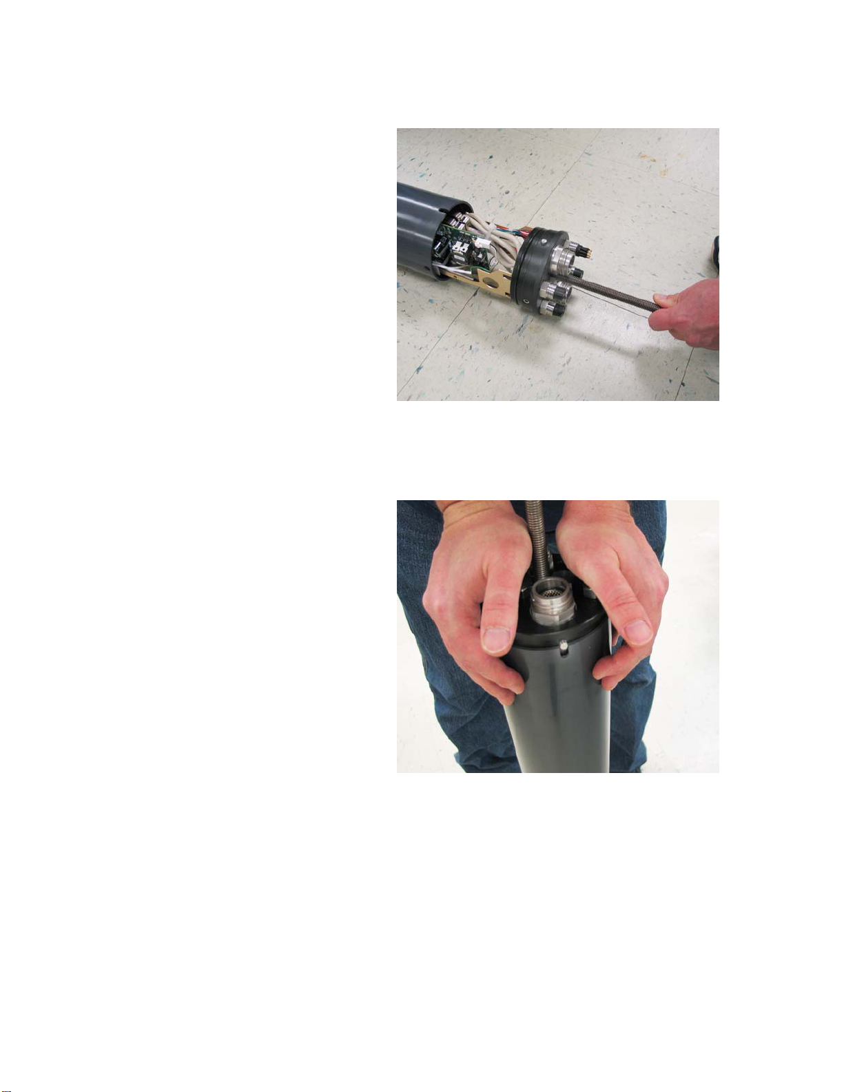
4-10 CHAPTER 4 Equipment Maintenance
Figure 4-14: Pulling the Sonar Electronics
Chassis out of the Sonar Electronics Housing
Figure 4-15: Aligning and Installing the
Connector End Cap
16. Lay the sonar electronics
housing on a dry, flat
surface, and then grasp the
threaded rod and carefully
pull the chassis completely
out of the housing. Be
careful not to scratch the
O-ring surface inside the
housing.
4.3.2 Reassembling the Sonar Head Unit
To reassemble the Sonar Head
Unit:
1. If the sonar electronics
chassis was removed, verify
that the O-ring on the
connector end cap is clean
and free of dirt or scratches.
If the chassis was not
removed, proceed to Step 5.
If dirt or scratches are
present, replace the O-ring.
When replacing the O-ring,
first clean the O-ring
surface inside the housing and the O-ring groove in the end cap using a lintfree cloth or paper towel, and then apply a light coat of silicone grease to the
O-ring before installing it.
2. Insert the chassis into the housing and align the locator pin in the end cap with the
slot in the housing.
3. Push the connector end cap into the housing until it is fully seated.
HydroChart 5000 Sonar Operations and Maintenance Manual P/N 11210080, Rev. 02
Page 65

Disassembling and Reassembling the Sonar Head Unit 4-11
Figure 4-16: Sonar Electronics Chassis
Installed in Frame with the Jumper and
Altimeter Cables
4. Loosen the two socket head
screws in the connector end
cap until the heads of the
screws are flush with the
outside surface of the
housing.
5. If the altimeter transducer
was removed, install it onto
the frame and lay the cable
along the inside of the frame
pulling all excess cable out
of the frame.
6. Lay the jumper cable along
the inside of the frame and
insert it through the
mounting flange leaving
enough length for connecting
to the deck cable.
7. Slide the sonar electronics
chassis into the frame and install and secure it to the angle bracket using the M6 x
12 mm socket head cap screw.
8. Referring to the sonar electronics housing connector end cap as shown in
Figure 4-17, connect the cables to the end cap as described below. Be sure that the
transducer cables pass through the large holes in the fairings.
• Port transducer black cable to the RX PORT connector.
• Port transducer blue cable to the TX PORT connector.
• Starboard transducer black cable to the RX STBD connector.
• Starboard transducer blue cable to the TX STBD connector.
• Jumper cable to the T/C connector.
• Altimeter cable to the ALT connector.
9. Loosely attach the lower and upper halves of the fairing using all twenty-two
of the M6 x 12 mm Phillips head screws.
10. Loosely attach the transducers to the frame using the twenty-four M5 x 20 mm
socket head cap screws.
11. Tighten all twenty-two of the M6 x 12 mm Phillips head screws attaching the
fairing.
12. Tighten all twenty-four of the M5 x 20 mm socket head cap screws attaching the
transducers.
13. Install the two skid plates using the six M6 x 18 mm socket head cap screws each
to complete the Sonar Head Unit reassembly as shown in Figure 4-18.
Page 66

4-12 CHAPTER 4 Equipment Maintenance
ALT
RX PORT
RX STBD
T/C
TX STBD
TX PORT
Figure 4-17: Sonar Electronics Housing Connector End Cap Connectors
Figure 4-18: Sonar Head Unit Fully Assembled
HydroChart 5000 Sonar Operations and Maintenance Manual P/N 11210080, Rev. 02
Page 67

APPENDIX A: GENERAL SETUP,
CONFIGURATION AND
TROUBLESHOOTING
Included in this appendix are basic setup and configuration instructions along with
other information useful for setting up and maintaining the HydroChart 5000
Sonar System. In addition, information is provided which can be helpful for
system troubleshooting should problems occur, including instructions on how to
verify operation of hardware components and transducers.
WARNING Klein Marine Systems recommends all troubleshooting be
done by a trained technician. Some circuits in the Transceiver and
Processing Unit (TPU) have voltages as high as 240 volts, and some
circuits in the sonar Sonar Head Unit have 1500 volts. You should familiarize yourself
with the location of these voltages before you attempt any troubleshooting. Failure to
observe these warnings could result in injuries to personnel.
A-1
CAUTION Serious damage to the sonar electronics may occur if the Sonar
Head Unit is operated out of the water for periods longer than 15 minutes.
Let the sonar cool 15 minutes or longer between operations. Protect the
Sonar Head Unit from dir ect exposure to the sun prior to and during operation in high
temperature climates.
CAUTION The depth rating on the transducers is 200 meters (656 feet).
Operations at depths greater than 200 meters may damage the tra nsd ucers.
Page 68

A-2 APPENDIX A General Setup, Configuration and Troubleshooting
A.1 Basic System Requirements
Although we suggest that you get the fastest available computer at the time of
purchase, it is recommended that you use the following minimum PC system.
• 2.0 GHz Intel Core 2 Duo Processor
• 1 GB RAM
• 80 GB hard drive
• 8 MB video card
• 100BaseT Ethernet card, such as a 3Com 3C905
• Windows XP or Windows 7
• Power backup module
When running the PC system it is important to make sure that you leave at least
500 MB of free disk space for temporary system disk swap files.
A.2 Basic System Setup
Refer to Figure A-1 for the basic system setup information. Also refer to
“CHAPTER 3: Preparation for Deployment,” for detailed connection information.
A.3 Installing SonarPro
Insert the SonarPro CD into your CD-ROM drive, and then locate the SonarPro
Installation.pdf file in the Documentation folder. Double-click this file to open it.
NOTE It is very important that you follow the instructions in the
Sonarpro Installation.pdf file. You should also print this file.
To install SonarPro double-click the setup.exe file in the SonarPro Disk1 folder
and follow the directions carefully. For an upgrade, double-click the setup.exe file
in the SonarPro Disk1 folder and follow the directions carefully. Multiple versions
of SonarPro can reside on the same computer. When installation is complete,
verify that your startup.ini file or your vxWorks files are located directly in the
klein directory
HydroChart 5000 Sonar Operations and Maintenance Manual P/N 11210080, Rev. 02
Page 69

Installing SonarPro A-3
SonarPro
Workstation
TPU
Sonar Head Unit
GPS
Motion
Reference
Unit
Figure A-1: HydroChart 5000 Sonar System Basic System Setup Diagram
Page 70

A-4 APPENDIX A General Setup, Configuration and Troubleshooting
A.4 Sonar Head Unit
The Sonar Head Unit is shown in Figure A-2.
Figure A-2: Sonar Head Unit
A.4.1 Checking the Telemetry Link to the Sonar Head Unit
Turn the TPU. The SYS READY indicator should flash. Then after approximately
1 minute, the T/F POWER indicator should turn on, the SYS READY indicator
should stop flashing and remain on, and the STATUS TRIGGER indicator should
begin flashing at the ping rate of the sonar.
A.4.2 Checking the Transmitters before Deployment
Each transducer assembly contains separate transmitter and receiver arrays. Each
transmitter array (one port, one starboard) is driven by one transmitter circuit.
NOTE The transmit transducers are electrically shielded. For this reason,
it is difficult to localize the source (port or starboard) of the waveform
picked up by the probe. To distinguish between the port and starboard
transmitters, ground the oscilloscope probe to the Sonar Head Unit skin while
searching near the middle of each transducer assembly for the signal.
HydroChart 5000 Sonar Operations and Maintenance Manual P/N 11210080, Rev. 02
Page 71

Sonar Head Unit A-5
To verify that the transmitters are working, run an oscilloscope probe with the
scope tip in place along the transducer and see the transmit waveform as in the
image in Figure A-3. If there is a problem with a transmitter, it will show up as a
very weak transmit waveform.
Figure A-3: Transmit Waveform
A.4.3 Checking the Receivers before Deployment
With the Sonar Head Unit running on deck, start SonarPro. Allow the TVG gain to
adjust, and then rub the transducers firmly , one trans ducer at a time. This is the rub
test. The image in the Sonar Viewer window should look something like that in
Figure A-4.
A.4.4 Setting up for Testing the Electronics
Remove the Sonar Head Unit electronics as described in “Disassembling and
Reassembling the Sonar Head Unit” on page 4-3 and place the electronics in a
position so that you can reconnect the transducers.
A.4.5 Checking the Multiplexer Board
The Multiplexer board performs the following functions:
• Receives the 200 VDC and telemetry from the surface and
separates out the telemetry from the 200 VDC.
• Routes the 200 VDC to the power supply, and then receives the
converted ±12 VDC.
• Routes the 200 VDC to the Transmitter boards.
Page 72
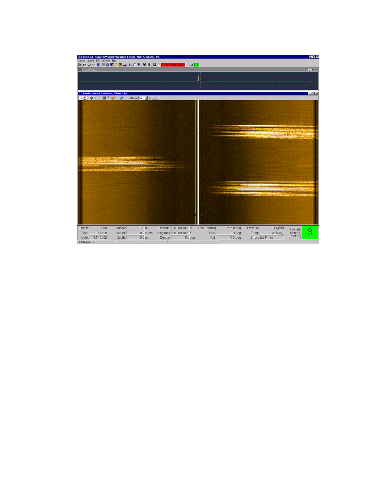
A-6 APPENDIX A General Setup, Configuration and Troubleshooting
Figure A-4: Image in Sonar Viewer Window During a Rub Test
• Generates ±5 VDC, +3.3 VDC, and +28 VDC.
• Generates the time varied gain (TVG) curves for the received
sonar signals from the transducers.
• Multiplexes all the data channels and transmits the telemetry back
to the surface.
• Provides cable uplink and downlink interface, as well as electrical
output for external fiber uplink.
200 VDC is indicated by bright orange LED D40. The voltage can be checked at
JP8. The +5 volts is generated by a switching regulator and indicated by green
LED D37. The voltage can be checked at L37. TPGND1 provides a ground
reference. A second switching regulator generates -5 VDC, indicated by green
LED D38, and measurable at L30. A third switching regulator generates +3.3
VDC, indicated by green LED D39 and measurable at L26. (Be sure to measure at
the output side of L26.) +28 VDC is generated by a fourth switching regulator,
which can be measured at TP25. Use TPGND8 for ground reference. A linear
regulator generates 2.5 VDC from the 3.3 VDC source. This is indicated by green
HydroChart 5000 Sonar Operations and Maintenance Manual P/N 11210080, Rev. 02
Page 73
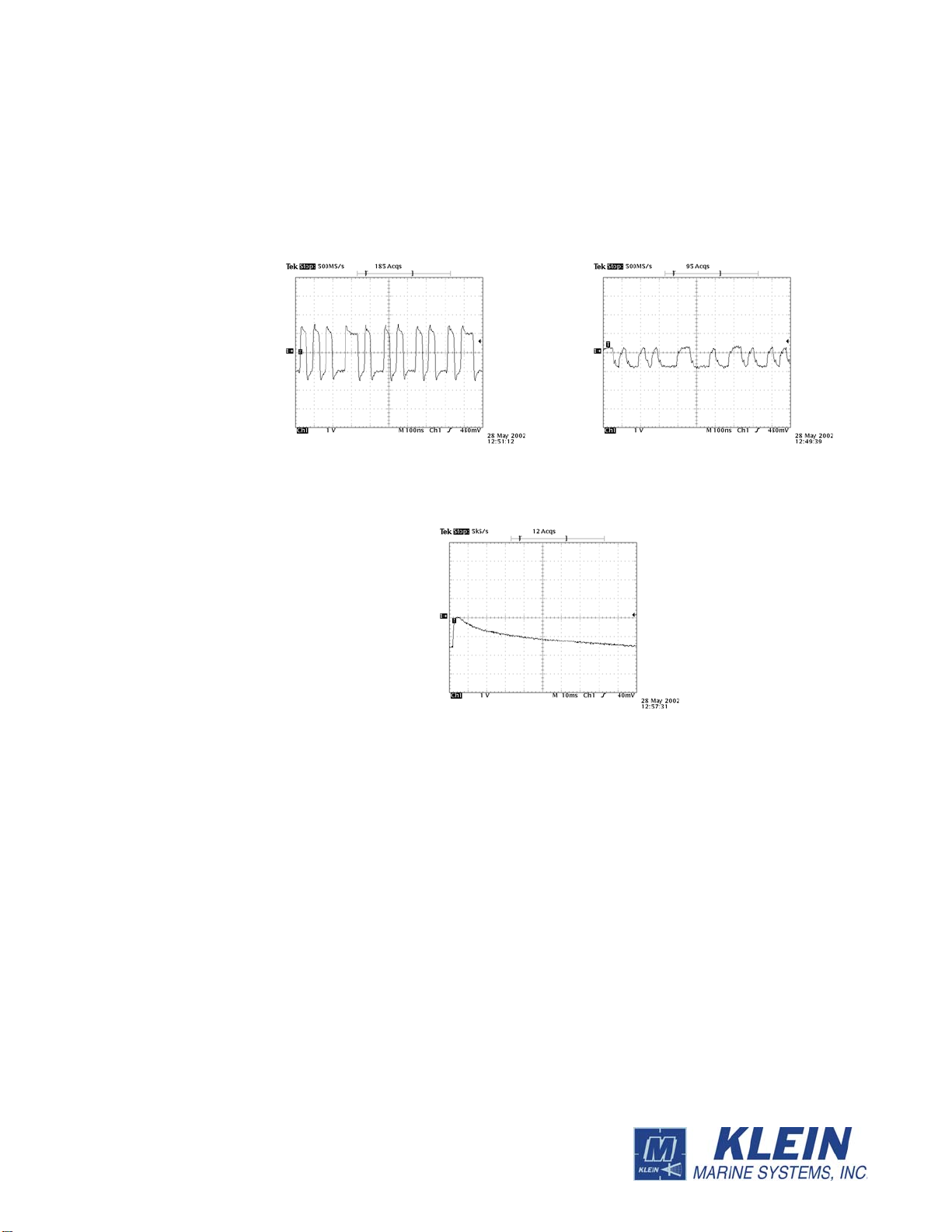
Sonar Head Unit A-7
TP18 Telemetry
TP17
TP28 TVG curve
LED D9, and measurable at TP9. TPGND1 can be used for ground reference. A
second linear regulator generates 1.2 VDC from the 3.3 VDC source. This is
indicated by green LED D11, and can be measured at TP10.
Some useful test points and waveforms are shown in Figure A-5.
Figure A-5: Multiplexer Board Waveforms
A.4.6 Checking the Transmitter Board
By probing on the Transmitter board you can check that the transmitters are
working. Probe each transmitter output connector (J5-1, 2; J6-1, 2) to view the two
transmitter outputs. These are floating differential output pairs, so the signal levels
at pin 1 and 2 may be unequal. But all four pins should show transmitter outputs
similar to that shown in Figure A -6, and you should see a scope trace similar to the
one shown in the figure. You can select different pulse lengths on the System 5000
Control tab of the Sonar Interface dialog box. Note that pulse lengths of 2 ms and
greater are generated at a lower amplitude than shorter pulse lengths. The altimeter
transmitter can be checked at J7-1.
Page 74
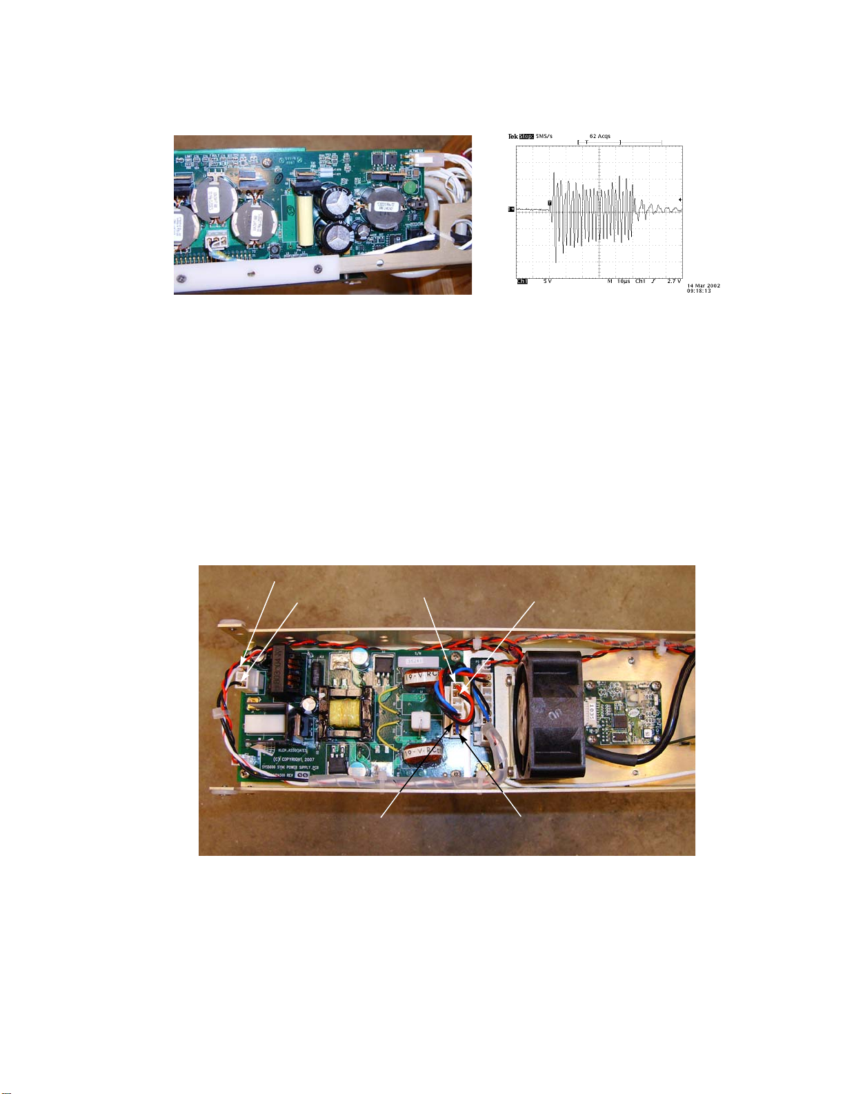
A-8 APPENDIX A General Setup, Configuration and Troubleshooting
-12 VDC
GND
GND
+12 VDC
GND
+200 VDC
Figure A-6: Sample Transmit Waveform
A.4.7 Checking the Receiver Boards
If your sonar image seems to be having problems on one side, this is an indication
that you may have a receiver problem. Try swapping the receiver boards and see if
the problem follows the board.
A.4.8 Sonar Head Unit Power Supply Pinouts
The Sonar Head Unit power supply pinouts are shown in Figure A-7 .
Figure A-7: The Sonar Head Unit Power Supply Pinouts
HydroChart 5000 Sonar Operations and Maintenance Manual P/N 11210080, Rev. 02
Page 75

Spare Boards and Components A-9
A.5 Spare Boards and Components
Listed in Table A-1 and Table A-2 are the recommended spare boards and
components. In addition, refer to Appendix B "Drawings," for additional
components and their part numbers.
Table A-1: TPU Spares
QTY P/N DESCRIPTION
1 14105785 Demultiplexer Board
1 14105873 CPU Board
1 11700098 200V Power Supply Board
1 14104980 200V Power Filter Board
1 11700092 12V Power Supply Board
1 14105397 12V Power Filter Board
Table A-2: Sonar Head Unit Spares
QTY P/N DESCRIPTION
1 14104941 Multiplexer Board
1 14104530 Transmitter Board
1 14104932-02 Receiver Board
1 14104506 Power Supply Board
1 14104605-01 Altimeter, 455 Khz
In addition, a spare deck cable is recommended.
Page 76

A-10 APPENDIX A General Setup, Configuration and Troubleshooting
A.6 Cable Pinouts
Figure A-8: Cable Pinouts
A.7 NMEA 0183 Formats and Information
HydroChart 5000 Sonar Operations and Maintenance Manual P/N 11210080, Rev. 02
Page 77

NMEA 0183 Formats and Information A-11
Page 78
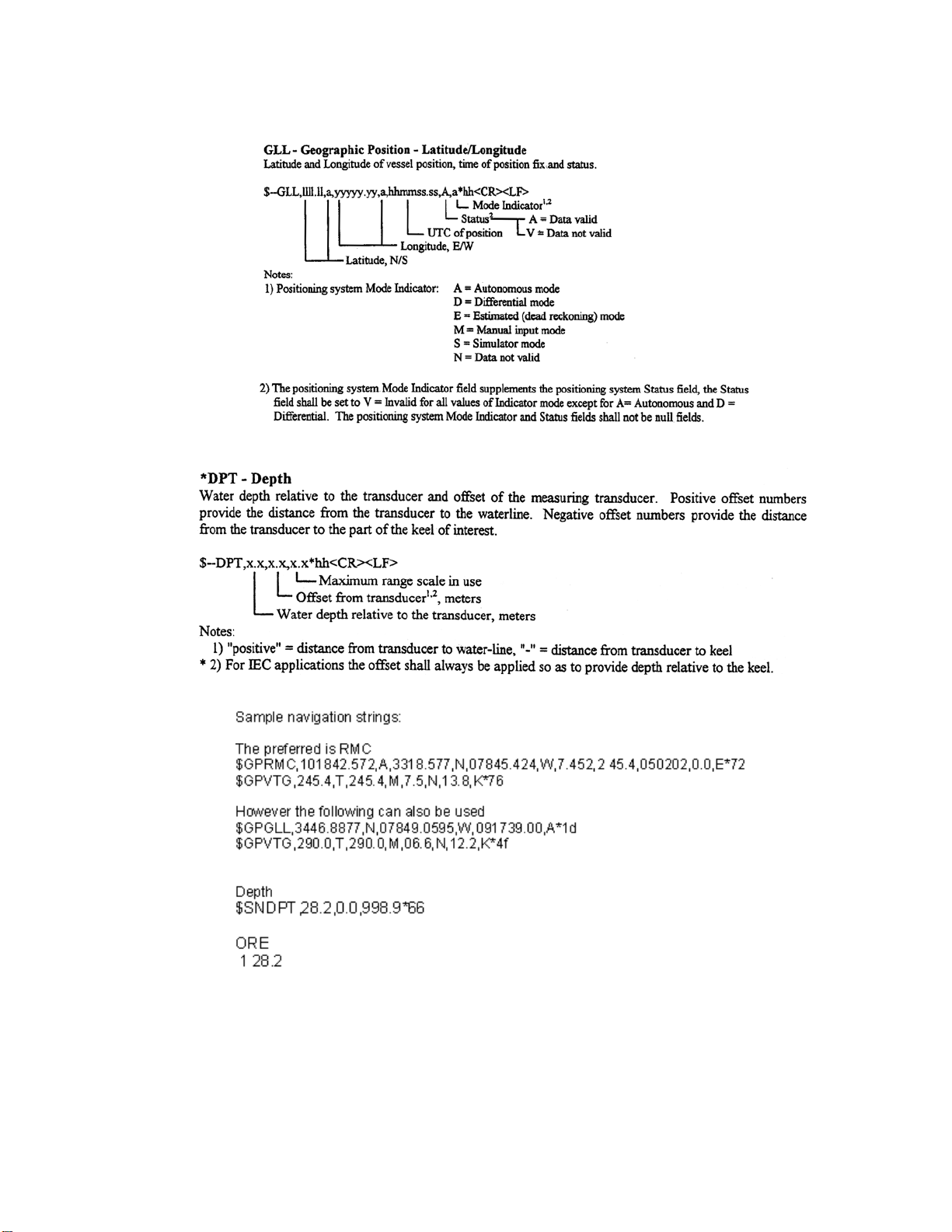
A-12 APPENDIX A General Setup, Configuration and Troubleshooting
HydroChart 5000 Sonar Operations and Maintenance Manual P/N 11210080, Rev. 02
Page 79

APPENDIX B: DRAWINGS
Listed in Table B-1 are the drawings included in this appendix.
Table B-1: List of Drawings
B-1
DRAWING
NO.
14605080
14605912
15100918
TITLE
Outline Drawing, HydroChart 5000
Outline Drawing, TPU
Assembly Drawing, Deck Cable w/ 8-Pin Micro Connector
Page 80

HydroChart 5000 Sonar Operations and Maintenance Manual P/N 11210080, Rev. 02
B-2 APPENDIX B Drawings
Page 81

B-3
Page 82

HydroChart 5000 Sonar Operations and Maintenance Manual P/N 11210080, Rev. 02
B-4 APPENDIX B Drawings
 Loading...