

SERIES 5000 V2 SONAR
SYSTEM
Operations and Maintenance Manual
P/N 11214512, Rev. 04
11 Klein Drive
Salem, NH 03079-1249
U.S.A.
Tel: (603) 893-6131
Fax: (603) 893-8807
www.KleinMarineSystems.com

ii
This document contains proprietary information, and such information may not be
disclosed to others for any purpose or used for any manufacturing purpose without
expressed written permission from Klein Marine Systems, Inc. (KMS). The
information provided is for informational purposes only and is subject to change
without notice. KMS assumes no responsibility or liability for any errors,
inaccuracies or omissions that may be present in this document.
The SonarPro software program may be used or copied only in accordance with
the terms of the Software License Agreement.
©
Copyright 2008–2019 by Klein Marine Systems, Inc. All rights reserved.
SonarPro® is a registered trademark of Klein Marine Systems, Inc.
K-Wing® and K-Wing II® are a registered trademarks of Klein Marine Systems,
Inc.
Intel® and Pentium®are registered trademarks of Intel Corporation.
Windows® and Wordpad® are registered trademarks of Microsoft Corporation.
Kevlar® is a registered trademark of the DuPont Company.
Series 5000 V2 Sonar System Operations and Maintenance Manual P/N 11214512, Rev. 04

WARNING
Klein Marine Systems, Inc. recommends all troubleshooting be
done by a trained technician. Some circuits in the Sonar
Transceiver and Processing Unit have voltages as high as 240 volts,
and some circuits in the sonar towfish have 1500 volts. You should
familiarize yourself with the location of these voltages before you
attempt any troubleshooting. Failure to observe these warnings
could result in injuries to personnel.
CAUTION
Serious damage to the sonar electronics may occur if the sonar
towfish is operated out of the water for periods longer than 15
minutes. Let the sonar cool 15 minutes or longer between
operations. Protect the sonar towfish from direct exposure to the
sun prior to and during operation in high temperature climates.
iii
CAUTION
The depth rating on the transducers for the Series 5000 V2 Sonar
System is 500 meters (1640 feet). Operations at depths greater than
500 meters may damage the transducers. For a Series 5000 V2
Sonar System with bathymetry option, the depth rating is
200 meters (656 feet). Operations at depths greater than 200 meters
may damage the transducers.
STANDARDS
SAFETY: EN 60950
EMC: EN 60945

iv
Table of Contents
Table of Contents . . . . . . . . . . . . . . . . . . . . . . . . . . . . . . . . . . . . . . . . . . . . iv
List of Figures . . . . . . . . . . . . . . . . . . . . . . . . . . . . . . . . . . . . . . . . . . . . . . viii
List of Tables . . . . . . . . . . . . . . . . . . . . . . . . . . . . . . . . . . . . . . . . . . . . . . . . x
Sonar System Warranty . . . . . . . . . . . . . . . . . . . . . . . . . . . . . . . . . . . . . . . xi
What Is Covered . . . . . . . . . . . . . . . . . . . . . . . . . . . . . . . . . . . . . . . . . . . xi
Conditions Of Warranty . . . . . . . . . . . . . . . . . . . . . . . . . . . . . . . . . . . . xii
Changes, Errors And Omissions . . . . . . . . . . . . . . . . . . . . . . . . . . . . . . xiii
Software License Agreement . . . . . . . . . . . . . . . . . . . . . . . . . . . . . . . . . . xiv
Preface . . . . . . . . . . . . . . . . . . . . . . . . . . . . . . . . . . . . . . . . . . . . . . . . . . . xvi
What’s in This Manual . . . . . . . . . . . . . . . . . . . . . . . . . . . . . . . . . . . . . xvi
Note, Warning, Caution, and Shock Hazard Notices . . . . . . . . . . . . . xvii
Customer Service . . . . . . . . . . . . . . . . . . . . . . . . . . . . . . . . . . . . . . . . . . xviii
CHAPTER 1: Overview . . . . . . . . . . . . . . . . . . . . . . . . . . . . . . . . . . . 1-1
1.1 Main Features . . . . . . . . . . . . . . . . . . . . . . . . . . . . . . . . . . . . . . . 1-1
1.2 System Components . . . . . . . . . . . . . . . . . . . . . . . . . . . . . . . . . . 1-2
1.2.1 Towfish . . . . . . . . . . . . . . . . . . . . . . . . . . . . . . . . . . . . . . . . . . 1-2
1.2.2 TPU . . . . . . . . . . . . . . . . . . . . . . . . . . . . . . . . . . . . . . . . . . . . . 1-2
1.2.3 SonarPro Workstation . . . . . . . . . . . . . . . . . . . . . . . . . . . . . . 1-5
CHAPTER 2: Specifications . . . . . . . . . . . . . . . . . . . . . . . . . . . . . . . 2-1
2.1 Sonar System . . . . . . . . . . . . . . . . . . . . . . . . . . . . . . . . . . . . . . . 2-1
2.2 Topside System . . . . . . . . . . . . . . . . . . . . . . . . . . . . . . . . . . . . . 2-2
2.2.1 System Power Requirements . . . . . . . . . . . . . . . . . . . . . . . . . 2-2
2.2.2 TPU . . . . . . . . . . . . . . . . . . . . . . . . . . . . . . . . . . . . . . . . . . . . . 2-2
2.2.3 SonarPro Workstation . . . . . . . . . . . . . . . . . . . . . . . . . . . . . . 2-2
2.3 Towfish . . . . . . . . . . . . . . . . . . . . . . . . . . . . . . . . . . . . . . . . . . . 2-3
2.3.1 General . . . . . . . . . . . . . . . . . . . . . . . . . . . . . . . . . . . . . . . . . . 2-3
2.3.2 Transducers . . . . . . . . . . . . . . . . . . . . . . . . . . . . . . . . . . . . . . . 2-3
2.3.3 Transmitter . . . . . . . . . . . . . . . . . . . . . . . . . . . . . . . . . . . . . . . 2-3
2.3.4 Receiver . . . . . . . . . . . . . . . . . . . . . . . . . . . . . . . . . . . . . . . . . 2-3
2.3.5 A/D Converter . . . . . . . . . . . . . . . . . . . . . . . . . . . . . . . . . . . . 2-4
Series 5000 V2 Sonar System Operations and Maintenance Manual P/N 11214512, Rev. 04

2.3.6 Multiplexer . . . . . . . . . . . . . . . . . . . . . . . . . . . . . . . . . . . . . . . 2-4
2.3.7 Power . . . . . . . . . . . . . . . . . . . . . . . . . . . . . . . . . . . . . . . . . . . 2-4
2.3.8 Heading Sensor . . . . . . . . . . . . . . . . . . . . . . . . . . . . . . . . . . . . 2-4
2.3.9 Pitch and Roll Sensor . . . . . . . . . . . . . . . . . . . . . . . . . . . . . . . 2-4
2.3.10 Pressure Sensor . . . . . . . . . . . . . . . . . . . . . . . . . . . . . . . . . . . . 2-4
2.4 Tow Cables . . . . . . . . . . . . . . . . . . . . . . . . . . . . . . . . . . . . . . . . 2-5
2.4.1 Lightweight Coaxial Deck Cable . . . . . . . . . . . . . . . . . . . . . . 2-5
2.4.2 Armored Coaxial Tow Cable (0.40) . . . . . . . . . . . . . . . . . . . . 2-5
2.4.3 Armored Coaxial Tow Cable (0.68) . . . . . . . . . . . . . . . . . . . . 2-5
2.5 Towfish Options . . . . . . . . . . . . . . . . . . . . . . . . . . . . . . . . . . . . . 2-6
2.6 Tow Cable Options . . . . . . . . . . . . . . . . . . . . . . . . . . . . . . . . . . 2-6
CHAPTER 3: Preparation for Use . . . . . . . . . . . . . . . . . . . . . . . . . . . 3-1
v
3.1 Unpacking and Inspection . . . . . . . . . . . . . . . . . . . . . . . . . . . . . 3-1
3.2 Locating the Topside System Components . . . . . . . . . . . . . . . . 3-1
3.3 Power Requirements . . . . . . . . . . . . . . . . . . . . . . . . . . . . . . . . . 3-1
3.3.1 Grounding . . . . . . . . . . . . . . . . . . . . . . . . . . . . . . . . . . . . . . . . 3-2
3.3.2 TPU and SonarPro Workstation Circuit Breakers . . . . . . . . . 3-2
3.4 Towfish Setup . . . . . . . . . . . . . . . . . . . . . . . . . . . . . . . . . . . . . . 3-2
3.4.1 Connecting the Tow Cable . . . . . . . . . . . . . . . . . . . . . . . . . . . 3-3
3.4.2 Connecting the Tow Cable with the Optional K-Wing
Depressor . . . . . . . . . . . . . . . . . . . . . . . . . . . . . . . . . . . . . . . . 3-4
3.4.3 Disconnecting the Tow Cable from the Towfish . . . . . . . . . . 3-5
3.5 Topside System Connections . . . . . . . . . . . . . . . . . . . . . . . . . . . 3-6
3.5.1 TPU Connections . . . . . . . . . . . . . . . . . . . . . . . . . . . . . . . . . . 3-6
3.5.2 SonarPro Workstation Connections . . . . . . . . . . . . . . . . . . . . 3-8
3.6 Connecting the Topside System Components . . . . . . . . . . . . . 3-10
3.7 Topside System Controls and Indicators . . . . . . . . . . . . . . . . . 3-11
3.7.1 TPU Controls and Indicators . . . . . . . . . . . . . . . . . . . . . . . . 3-11
3.7.2 SonarPro Workstation Controls and Indicators . . . . . . . . . . 3-13
3.8 System Activation and Test . . . . . . . . . . . . . . . . . . . . . . . . . . . 3-15
3.8.1 Activating and Testing the System on Deck . . . . . . . . . . . . 3-15
3.8.2 Activating and Testing the System at Sea . . . . . . . . . . . . . . 3-16

vi
CHAPTER 4: Maintenance and Troubleshooting . . . . . . . . . . . . . . 4-1
4.1 General Maintenance Recommendations . . . . . . . . . . . . . . . . . . 4-1
4.2 Maintenance Checklists . . . . . . . . . . . . . . . . . . . . . . . . . . . . . . . 4-2
4.2.1 Daily Maintenance Checklist . . . . . . . . . . . . . . . . . . . . . . . . . 4-2
4.2.2 Weekly Maintenance Checklist . . . . . . . . . . . . . . . . . . . . . . . 4-2
4.2.3 Long Term Maintenance Checklist . . . . . . . . . . . . . . . . . . . . 4-2
4.3 Replacing the Fixed Tail Cone Assembly . . . . . . . . . . . . . . . . . 4-3
4.4 Removing the Fixed Tail Cone Assembly . . . . . . . . . . . . . . . . . 4-6
4.5 Removing the Towfish Electronics . . . . . . . . . . . . . . . . . . . . . . 4-7
4.6 Installing the Towfish Electronics . . . . . . . . . . . . . . . . . . . . . . . 4-8
4.7 Testing the Towfish Electronics . . . . . . . . . . . . . . . . . . . . . . . . 4-9
4.7.1 Checking the Multiplexer Board . . . . . . . . . . . . . . . . . . . . . 4-10
4.7.2 Checking the Transmitter Board . . . . . . . . . . . . . . . . . . . . . 4-10
4.7.3 Checking the Receiver Boards . . . . . . . . . . . . . . . . . . . . . . . 4-10
4.7.4 Checking the Sensors . . . . . . . . . . . . . . . . . . . . . . . . . . . . . . 4-12
4.7.5 Calibrating the Optional Temperature Probe . . . . . . . . . . . . 4-12
4.7.6 Calibrating the Compass . . . . . . . . . . . . . . . . . . . . . . . . . . . . 4-12
CHAPTER 5: Technical Description . . . . . . . . . . . . . . . . . . . . . . . . 5-1
5.1 Towfish . . . . . . . . . . . . . . . . . . . . . . . . . . . . . . . . . . . . . . . . . . . 5-1
5.1.1 Sonar Electronics . . . . . . . . . . . . . . . . . . . . . . . . . . . . . . . . . . 5-1
5.1.2 Transducer Arrays . . . . . . . . . . . . . . . . . . . . . . . . . . . . . . . . . 5-4
5.2 TPU . . . . . . . . . . . . . . . . . . . . . . . . . . . . . . . . . . . . . . . . . . . . . . 5-5
APPENDIX A: Sample Towing Characteristics . . . . . . . . . . . . . . . . A-1
APPENDIX B: Notes on Handling Tow Cables . . . . . . . . . . . . . . . . . B-1
B.1 Unreeling Tow Cable . . . . . . . . . . . . . . . . . . . . . . . . . . . . . . . . . B-1
B.2 Uncoiling Tow Cable . . . . . . . . . . . . . . . . . . . . . . . . . . . . . . . . . B-2
B.3 Cable Kinking . . . . . . . . . . . . . . . . . . . . . . . . . . . . . . . . . . . . . . B-2
B.3.1 Cause of Cable Kinking . . . . . . . . . . . . . . . . . . . . . . . . . . . . . B-2
B.3.2 Effect of Cable Kinking . . . . . . . . . . . . . . . . . . . . . . . . . . . . . B-3
B.3.3 Result of Cable Kinking . . . . . . . . . . . . . . . . . . . . . . . . . . . . . B-3
Series 5000 V2 Sonar System Operations and Maintenance Manual P/N 11214512, Rev. 04

vii
APPENDIX C: Configuring and Updating the TPU . . . . . . . . . . . . . C-1
C.1 Starting Linux TPU Updater . . . . . . . . . . . . . . . . . . . . . . . . . . . C-1
C.2 Querying or Changing the TPU IP Address . . . . . . . . . . . . . . . . C-2
C.3 Editing the TPU Startup File . . . . . . . . . . . . . . . . . . . . . . . . . . . C-3
C.4 Updating the TPU Software . . . . . . . . . . . . . . . . . . . . . . . . . . . . C-4
APPENDIX D: Different Tow Cable Lengths and the Startup.ini
File . . . . . . . . . . . . . . . . . . . . . . . . . . . . . . . . . . . . . . . D-1
D.1 Measuring Cable Insertion Loss . . . . . . . . . . . . . . . . . . . . . . . D-2
D.2 Spare Tow Cable . . . . . . . . . . . . . . . . . . . . . . . . . . . . . . . . . . . D-3
APPENDIX E: Drawings and Parts Lists . . . . . . . . . . . . . . . . . . . . . E-1

viii
List of Figures
Figure 1-1: Series 5000 Towfish . . . . . . . . . . . . . . . . . . . . . . . . . . . . . . . . . . . . . . . . . . . 1-3
Figure 1-2: Series 5000 V2 Sonar System Topside System Main Components . . . . . . . . 1-4
Figure 3-1: TPU Back Panel . . . . . . . . . . . . . . . . . . . . . . . . . . . . . . . . . . . . . . . . . . . . . . 3-7
Figure 3-2: SonarPro Workstation Back Panel . . . . . . . . . . . . . . . . . . . . . . . . . . . . . . . . 3-9
Figure 3-3: TPU Front Panel . . . . . . . . . . . . . . . . . . . . . . . . . . . . . . . . . . . . . . . . . . . . 3-12
Figure 3-4: SonarPro Workstation Front Panel . . . . . . . . . . . . . . . . . . . . . . . . . . . . . . 3-14
Figure 4-1: Towfish Tail with Rear Center Pin in Place . . . . . . . . . . . . . . . . . . . . . . . . . 4-3
Figure 4-2: Tail Cone being Aligned and Attached to Towfish . . . . . . . . . . . . . . . . . . . . 4-4
Figure 4-3: Tail Cone Being Tightened with Hex Key . . . . . . . . . . . . . . . . . . . . . . . . . . 4-4
Figure 4-4: Crossbar Used to Secure Tail Cone Parts . . . . . . . . . . . . . . . . . . . . . . . . . . 4-5
Figure 4-5: Tail Cone Being Tightened With Screwdriver and Key . . . . . . . . . . . . . . . . 4-5
Figure 4-6: Tail Fins being Inserted into Tail Cone . . . . . . . . . . . . . . . . . . . . . . . . . . . . 4-6
Figure 4-7: Tail Fins being Secured to Tail Cone . . . . . . . . . . . . . . . . . . . . . . . . . . . . . . 4-6
Figure 4-8: Push/Pull Assembly . . . . . . . . . . . . . . . . . . . . . . . . . . . . . . . . . . . . . . . . . . . 4-7
Figure 4-9: Jacking Screw . . . . . . . . . . . . . . . . . . . . . . . . . . . . . . . . . . . . . . . . . . . . . . . . 4-7
Figure 4-10: Electronics Housing End Cap Bulkhead Connectors . . . . . . . . . . . . . . . . . . 4-8
Figure 4-11: Altimeter Cable Identified with Colored Shrink Tubing . . . . . . . . . . . . . . . . 4-8
Figure 4-12: Towfish Electronics Ready for Servicing . . . . . . . . . . . . . . . . . . . . . . . . . . . 4-9
Figure 4-13: Multiplexer Board Waveforms . . . . . . . . . . . . . . . . . . . . . . . . . . . . . . . . . . 4-11
Figure 4-14: Sample Transmit Waveform . . . . . . . . . . . . . . . . . . . . . . . . . . . . . . . . . . . . 4-11
Figure 4-15: The Sensor Interface Board . . . . . . . . . . . . . . . . . . . . . . . . . . . . . . . . . . . . 4-12
Figure 5-1: Towfish Block Diagram—12 Sidescan Channels and 3 Bathymetery
Channels . . . . . . . . . . . . . . . . . . . . . . . . . . . . . . . . . . . . . . . . . . . . . . . . . . . . 5-2
Figure 5-2: The Series 5000 V2 Sonar System TPU Electronics Chassis . . . . . . . . . . . . 5-3
Figure 5-3: The Series 5000 V2 Sonar System TPU Electronics Block Diagram . . . . . . 5-6
Figure 5-4: The Series 5000 V2 Sonar System TPU Electronics Chassis . . . . . . . . . . . . 5-7
Figure A-1: Cable Length vs. Towfish Depth Graph 1 . . . . . . . . . . . . . . . . . . . . . . . . . . A-3
Series 5000 V2 Sonar System Operations and Maintenance Manual P/N 11214512, Rev. 04

ix
Figure A-2: Cable Length vs. Towfish Depth Graph 2 . . . . . . . . . . . . . . . . . . . . . . . . . . A-4
Figure A-3: Cable Length vs. Towfish Depth Graph 3 . . . . . . . . . . . . . . . . . . . . . . . . . . A-5
Figure A-4: Cable Length vs. Towfish Depth Graph 4 . . . . . . . . . . . . . . . . . . . . . . . . . . A-6
Figure A-5: Cable Length vs. Towfish Depth Graph 5 . . . . . . . . . . . . . . . . . . . . . . . . . . A-7
Figure B-1: Correct Methods to Unreel Tow Cable . . . . . . . . . . . . . . . . . . . . . . . . . . . . B-1
Figure B-2: Spooling Real to Drum . . . . . . . . . . . . . . . . . . . . . . . . . . . . . . . . . . . . . . . . . B-2
Figure B-3: Cable Loop and Kink . . . . . . . . . . . . . . . . . . . . . . . . . . . . . . . . . . . . . . . . . . B-3
Figure B-4: Damaged Cable . . . . . . . . . . . . . . . . . . . . . . . . . . . . . . . . . . . . . . . . . . . . . . B-3
Figure C-1: The Klein Linux TPU Updater Dialog Box . . . . . . . . . . . . . . . . . . . . . . . . . C-1
Figure C-2: The Select RS-232 Port Dialog Box. . . . . . . . . . . . . . . . . . . . . . . . . . . . . . . C-2
Figure C-3: The Klein Linux TPU Updater Dialog Box with Current TPU IP
Address Displayed . . . . . . . . . . . . . . . . . . . . . . . . . . . . . . . . . . . . . . . . . . . . C-3
Figure D-1: Sample Plot of Tow Cable Characteristics . . . . . . . . . . . . . . . . . . . . . . . . . D-2
Figure D-2: Setup for Measuring Tow Cable Characteristics using a Function
Generator, Terminator and Oscilloscope . . . . . . . . . . . . . . . . . . . . . . . . . . . D-3

x
List of Tables
Table 3-1: TPU Power Cable Wiring . . . . . . . . . . . . . . . . . . . . . . . . . . . . . . . . . . . . . . . . . 3-2
Table E-1: List of Drawings and Parts Lists . . . . . . . . . . . . . . . . . . . . . . . . . . . . . . . . . . . E-1
Series 5000 V2 Sonar System Operations and Maintenance Manual P/N 11214512, Rev. 04

Sonar System Warranty
What Is Covered
LIMITED WARRANTY Subject to the conditions set forth below, equipment
sold by Seller is warranted against defects in materials and workmanship, and
Seller will repair or exchange any parts proven to be malfunctioning under normal
use for one year (12 months) from the date of Delivery as follows:
a) SONAR and other associated manufactured products, with the following
exceptions:
b) All third party accessories, winches, magnetometers, Sonar Laptops or PCs, and
peripherals/accessories and third party software packages related to the Sonar
Product Line are limited to the warranty provided by original manufacturer.
c) This warranty does not apply to tow cables. If applicable, the manufacturer’s
warranty will be forwarded with the equipment.
EQUIPMENT NOT MANUFACTURED BY SELLER Carries only its
vendor’s warranty, which is hereby incorporated by reference.
xi
SERVICE WORK BY SELLER Warrants that ALL service work performed by
Seller’s technical and engineering employees will be performed in a good and
workmanlike manner, but its liability under this warranty is limited to the
obligation to remedy at Seller’s expense any such service work not performed
satisfactorily, upon receipt of written notice within ninety (90) days of the date of
performance of the work.
For authorized onsite service (excluding Side Scan Sonar category referenced as a.
SONAR) in which Seller has to travel to the installed equipment, travel costs (auto
mileage and tolls) up to 100 round trip highway miles and travel time of 2 hours,
will be allowed by Seller. The Overtime premium labor portion of service of
normal working hours is not covered by this Warranty. On-site warranty service is
capped at (4) hours per failure. Travel costs other than auto mileage, tolls and two
(2) hours travel time are specifically excluded on all products and services.
Travel costs which are excluded from coverage of this warranty include, but are
not limited to: taxi, launch fees, aircraft rental, airfare, subsistence, customs,
shipping, communication charges, etc.
During the warranty period, Seller will repair or, at its option, replace any
equipment that proves to be defective. Such repair or replacement is Buyer’s
exclusive right and remedy, and our only obligation, with respect to any defective
equipment.

xii
Conditions Of Warranty
a) Seller’s warranty policy does not apply to equipment which has been subjected to
accident, abuse, or misuse, shipping damage, alterations, incorrect and/or nonauthorized service or equipment on which the serial number plate has been
altered, mutilated or removed.
b) A suitable proof of purchase, such as, a paid commercial invoice, an installation
certificate signed by Seller or an authorized agent must be made available to
Seller or Seller’s authorized servicing agent at the time of the Warranty Service.
c) The warranties stated herein are in lieu of all other warranties, expressed or
implied, and of all other obligations or liabilities on the part of Seller. Seller
neither assumes nor authorizes any other person to assume for it any other
liability. The Buyer expressly waives any right, claim or cause of action that
might otherwise arise out of the purchase and use of Seller’s products or service.
d) Warranty is not transferable and only applies to the original Buyer.
e) Warranty does not cover equipment that has been repaired or modified other than
by Seller, or equipment that has been subjected to misuse or to negligent or
accidental mishandling.
f) Except where Seller has performed the installation of specific equipment, Seller
assumes no responsibility for damage incurred during installation of equipment or
by damage caused by no fault of the Seller.
g) This warranty does not cover routine system checkouts or alignment/calibration,
unless required by replacement of part(s) in the area being aligned.
h) Consumable items are specifically excluded from this Warranty.
i) Buyer is responsible for the prepayment of all freight charges, insurance,
customs, imposts, duties, etc., to return defective equipment to Seller and for
Seller to return the repaired or replaced equipment to buyer.
j) Equipment returned for warranty service must be packed to best commercial
standards to prevent shipping damage.
k) Warranty shall be void and Seller shall be released from all obligations u nder this
warranty if the equipment is operated with components other than those sold or
authorized by Seller.
l) This warranty is strictly limited to the terms and indicated herein, and no other
warranties or remedies shall be binding on Seller including, without limitation,
any warranties of merchantability or fitness for a particular purpose.
m) Repairs and replacements under warranty have the same warranty as the original
product for the remaining balance of the warranty period for the original product
existing prior to notice of the warranty claim.
Series 5000 V2 Sonar System Operations and Maintenance Manual P/N 11214512, Rev. 04

xiii
Any failure to meet the foregoing conditions of warranty will automatically void
this limited warranty. This warranty gives Buyer specific legal rights, and Buyer
may also have other rights, which vary from State to State, Province to Province or
Country to Country.
DISPUTES Seller and Buyer agree that all disputes in any way relating to, arising
under, connected with, or incident to this agreement, and over which the federal
courts have subject matter jurisdiction, shall be litigated, if at all, exclusively in the
United States District Court for the State of Delaware, and if necessary, the
corresponding appellate courts. Seller and Buyer further agree that all disputes in
any way relating to, arising under, connected with or incident to this contract, and
over which the federal courts do not have subject matter jurisdiction, shall be
litigated, if at all, exclusively in the Courts of the State of Delaware, and if
necessary, the corresponding appellate courts. Seller and Buyers expressly submit
themselves to the personal jurisdiction of the State of Delaware. Before resorting
to litigation, Seller and Buyer agree to enter into negotiations to resolve the
dispute. If Seller and Buyer are unable to resolve the dispute by good faith
negotiation, either Seller or Buyer may refer the matter to litigation.
LIMITATION OF LIABILITY TO THE MAXIMUM EXTENT PERMITTED
BY APPLICABLE LAW, SELLER SHALL NOT BE LIABLE UNDER ANY
THEORY AT LAW, IN EQUITY OR OTHERWISE FOR ANY SPECIAL,
EXEMPLAR Y, PUNITIVE, INCIDENT AL, INDIRECT , OR CONSEQUENTIAL
DAMAGES (EVEN IF SELLER HAS BEEN ADVISED OF SAME)
INCLUDING, WITHOUT LIMITATION, LOST PROFITS OR REVENUES,
THE ENTIRE LIABILITY OF SELLER FOR ANY CLAIM, LOSS, OR
DAMAGES UNDER ANY THEORY AT LAW, IN EQUITY, OR OTHERWISE,
INCLUDING, BUT NOT LIMITED TO CONTRACT, TORT, (INCLUDING
INTELLECTUAL PROPERTY INFRINGEMENT , AND NEGLIGENCE), AND
STRICT LIABILITY, ARISING OUT OF THIS AGREEMENT OR ANY
INDEMNIFICATION OBLIGATION THEREOF, THE PERFORMANCE OR
BREACH THEREOF, OR THE SUBJECT MATTER SHALL NOT IN ANY
EVENT EXCEED THE SUM OF PAYMENTS ACTUALLY MADE BY BUYER
TO SELLER PURSUANT TO THIS AGREEMENT , ANY ACTION AGAINST
SELLER MUST BE BROUGHT WITHIN ONE (1) YEAR AFTER THE CLAIM
AROSE.
Changes, Errors And Omissions
Klein Marine Systems, Inc. reserves the right to make changes to the design or
specifications at any time without incurring any obligation to modify previously
delivered sonar systems. In addition, while considerable effort has been made to
ensure that the information in this manual is accurate and complete, Klein Marine
Systems, Inc. assumes no liability for any errors or omissions.

xiv
Software License Agreement
This Software License Agreement is provided by Klein Marine Systems, Inc.
(KMS) for end users of SonarPro© software for the KMS Series 3000, UUV-3500,
3900, 4900, 5000, 5000 V2, 5900, HydroChart 3500, HydroChart 5000, and
D3500TF Sonar Systems.
YOU SHOULD CAREFULLY READ THE FOLLOWING TERMS AND
CONDITIONS BEFORE USING THIS PRODUCT. IT CONTAINS
SOFTWARE, THE USE OF WHICH IS LICENSED BY KMS, TO ITS
CUSTOMERS FOR THEIR USE ONLY, AS SET FORTH BELOW. IF YOU DO
NOT AGREE TO THE TERMS AND CONDITIONS OF THIS AGREEMENT ,
DO NOT USE THE SOFTWARE. USING ANY PART OF THE SOFTWARE
INDICATES THAT YOU ACCEPT THESE TERMS.
LICENSE: KMS grants you a nonexclusive license to use the accompanying
software programs(s) (the "Software") subject to the terms and restrictions set
forth in this License Agreement. You are not permitted to lease, rent, distribute or
sublicense the Software or to use the Software in a time-sharing arrangement or in
any other unauthorized manner. Further, no license is granted to you in the human
readable code of the Software (source code). Except as provided below, this
License Agreement does not grant you any rights to patents, copyrights, trade
secrets, trademarks, or any other rights in respect to the Software.
The Software is licensed to be used on any workstation or any network server
owned by or leased to you, provided that the Software is used only in connection
with one KMS Series 3000, UUV-3500, 3900, 4900, 5000, 5000 V2, 5900,
HydroChart 3500, HydroChart 5000, or D3500TF Sonar System. You may
reproduce and provide authorized copies only of the Software and supporting
documentation for each such workstation or network server for this equipment on
which the Software is used as permitted hereunder. Otherwise, the Software and
supporting documentation may be copied only as essential for backup or archive
purposes in support of your use of the Software as permitted hereunder. You must
reproduce and include all copyright notices and any other proprietary rights
notices appearing on the Software and the supporting documentation on any copies
that you make.
NO ASSIGNMENT; NO REVERSE ENGINEERING: You may not transfer
or assign the Software and/or this License Agreement to another party without the
prior written consent of KMS. If such consent is given and you transfer or assign
the Software and/or this License Agreement, then you must at the same time either
transfer all copies of the Software as well as the supporting documentation to the
same party or destroy any such materials not transferred. Except as set forth above,
you may not transfer or assign the Software or your rights under this License
Agreement.
Modification, reverse engineering, reverse compiling, or disassembly of the
Software is expressly prohibited. You may not translate or create derivative works
of the software or the supporting documentation.
Series 5000 V2 Sonar System Operations and Maintenance Manual P/N 11214512, Rev. 04

xv
BATHYMETRIC PROCESSING A TTRIBUTION: Bathymetric processing
derived from DGA/GESMA publication in IEEE OCEAN'S 05 Europe
Conference Proceedings: "Bathymetric Sidescan Sonar: a System Dedicated to
Rapid Environment assessment, ref: 10.1109/OCEANSE.2005.1511695.
EXPORT RESTRICTIONS: You agree that you will not export or re-export the
Software or accompanying documentation (or any copies thereof) or any products
utilizing the Software or such documentation in violation of any applicable laws or
regulations of the United States or the country in which you obtained them.
TRADE SECRETS; TITLE: You acknowledge and agree that the structure,
sequence and organization of the Software are the valuable trade secrets of KMS.
You agree to hold such trade secrets in confidence. You further acknowledge and
agree that ownership of, and title to, the Software and all subsequent copies thereof
regardless of the form or media are held by KMS.
UNITED STATES GOVERNMENT LEGEND: All technical data and
Software are commercial in nature and developed solely at private expense. The
Software is delivered as Commercial Computer Software as defined in DFARS
252.227-7014 (June 1995) or as a commercial item as defined in F AR 2.101(a) and
as such is provided with only such rights as are provided in this License
Agreement, which is KMS's standard commercial license for Software. Technical
data is provided with limited rights only, as provided in DFAR 252.227-7015
(Nov. 1995) or FAR 52.227-14 (June 1987), whichever is applicable. You agree
not to remove or deface any portion of any legend provided on any licensed
program or documentation delivered to you under this License Agreement.
TERM AND TERMINATION: This license will terminate immediately if you
fail to comply with any term or condition of this License Agreement. Upon such
termination you agree to destroy the Software and documentation, together with all
copies and merged portions in any form. You may terminate it at any time by
destroying the Software and documentation together with all copies and merged
portions in any form.
GOVERNING LAW: This License Agreement shall be governed by the laws of
the State of New Hampshire, USA. You agree that the United Nations Convention
on Contracts for the International Sales of Goods (1980) is hereby excluded in its
entirety from application to this License Agreement.
LIMITED WARRANTY; LIMITATION OF LIABILITY: All warranties and
limitations of liability applicable to the Software are as stated in the product
manual accompanying the Software. Such warranties and limitations of liability
are incorporated herein in their entirety by this reference.
SEVERABILITY: In the event any provision of this License Agreement is found
to be invalid, illegal or unenforceable, the validity, legality and enforceability of
any of the remaining provisions shall not in any way be affected or impaired and a
valid, legal and enforceable provision of similar intent and economic impact shall
be substituted therefore.

xvi
Preface
ENTIRE AGREEMENT : This License Agreement sets forth the entire
understanding and agreement between you and KMS supersedes all prior
agreements, whether written or oral, with respect to the Software, and may be
amended only in a writing signed by both parties.
The Series 5000 V2 Sonar System is a towed multibeam sonar comprising a towed
underwater platform and a topside system.
What’s in This Manual
This operations and maintenance manual provides information pertaining to the
setup and deployment, operation, general maintenance, and troubleshooting of the
Series 5000 V2 Sonar System. The manual is divided into the following four main
chapters and four appendices:
Chapter 1: Overview. Presents an overview of the Series 5000 V2 Sonar
System components, including both functional and physical descriptions of the
system.
Chapter 2: Specifications. Provides detailed physical and performance
specifications for the main components of the system, including the acoustic
transducers, the environmental and navigation sensors, and the available tow
cables.
Chapter 3: Preparation for Use. Provides instructions for unpacking and
setting up the Series 5000 V2 Sonar System components. It also includes a
pre-survey checkout procedure.
Chapter 4: Maintenance and Troubleshooting. Provides instructions on
how to perform maintenance and troubleshooting of the Series 5000 V2 Sonar
System and how to replace the fixed tail cone assembly and remove, install and
test the towfish electronics.
Chapter 5: Technical Description. Provides an overall technical
description of the Series 5000 V2 Sonar System towfish and TPU electronics,
including block diagrams, printed circuit board descriptions and chassis photos
with call outs.
Appendix A: Sample Towing Characteristics. Provides towing
characteristics charts which are helpful when planning survey equipment
requirements.
Appendix B: Notes on Handling Tow Cables. Contains information on
tow cable handling.
Series 5000 V2 Sonar System Operations and Maintenance Manual P/N 11214512, Rev. 04
xvii
Appendix C: Configuring and Updating the TPU. Provides instructions
on how to configure and update the Series 5000 V2 Sonar System TPU.
Appendix D: Different Tow Cable Lengths and the Startup.ini File.
Provides instructions on how to tune the Series 5000 V2 Sonar system for
optimum performance versus various cable lengths and how to measure cable
insertion loss.
Appendix E: Drawings and Parts Lists. Provides drawings and parts lists
for reference and troubleshooting purposes.
Note, Warning, Caution, and Shock Hazard Notices
Where applicable, note, warning, caution, and shock hazard notices are included
throughout this manual as follows:
NOTE Recommendations or general information that is particular to the
material being presented or a referral to another part of this manual or to
another manual.
WARNING Identifies a potential hazard that could cause personal injury
or death to yourself or to others.
CAUTION Identifies a potential hazard that could be damaging to
equipment or could result in the loss of data.
SHOCK HAZARD Identifies a potential electrical shock hazard that could
cause personal injury or death to yourself or to others.

xviii
Customer Service
KMS technical support can be contacted using any of the following means:
Mail
Klein Marine Systems, Inc.
11 Klein Drive
Salem, NH 03079
Email
TechSupport@KleinMarineSystems.com
Telephone
(603) 893-6131
Facsimile
(603) 893-8807
For more information about KMS and our products, please go to our Web site at
www.KleinMarineSystems.com.
Series 5000 V2 Sonar System Operations and Maintenance Manual P/N 11214512, Rev. 04

CHAPTER 1: OVERVIEW
The Series 5000 V2 Sonar System is a very high resolution, multibeam long range
sonar system that is ideally suited for surface mine counter measure applications
and hydrographic, geophysical, pipeline, and offshore surveys. The two primary
drawbacks of conventional side-looking sonars, along-track resolution and towing
speed limitation, have been addressed by simultaneously forming multiple
dynamically focused beams per side, per ping. This allows greater towing speeds
without the usual loss of bottom coverage while maintaining high resolution. The
system employs operator selectable chirp and continuous wave (CW) technologies
which, when coupled with KMS proprietary display algorithms, provides
extraordinary sea floor images. In addition, rugged construction, low weight and
simple setup enables operation from large or small vessels.
1.1 Main Features
1-1
The Series 5000 V2 Sonar System provides the following main features:
• High speed, high resolution, multibeam side scan sonar.
• 14-bit digital multiplexer for transmission of sonar and control
data over a single coaxial cable.
• PC based operation using SonarPro and the Windows operating
system.
• Operation at 455 kHz for ranges up to 150 meters.
• Flexible and expandable system configurations.
• Chirp and CW operating modes.
• 500-meter operating depth (200-meter with bathymetry option).
• Operation with up to 800 meters of coaxial 0.680-inch diameter
armored tow cable.
• Heading, pitch, roll and pressure sensors.
• Optional interfaces for a responder, acoustic positioning system
yaw rate sensor, and altimeter.
• Small, lightweight and simple to operate and maintain.

1-2 CHAPTER 1 Overview
1.2 System Components
The main components of the Series 5000 V2 Sonar System are the towfish and the
topside system. The towfish is the underwater component and is towed with an
armored coaxial tow cable up to 800 meters in length. The topside system provides
the power source for the towfish and receives, stores and processes data acquired
by the towfish. The towfish connects to the topside system using an optionally
supplied winch with slip rings and an armored coaxial tow cable. A terminated,
light weight deck cable is optionally supplied for connecting to the winch or for
connecting directly to the towfish for testing. The topside system is composed of
two separate main components:
• Transceiver and Processing Unit (TPU)
• SonarPro Workstation
In addition, a K-Wing I or K-Wing II Depressor can be installed on the towfish
which enables a greater towing depth with less cable deployed.
1.2.1 Towfish
The towfish, which is shown in Figure 1-1, consists of a negatively buoyant
stainless steel towfish housing with attached port and starboard sonar transducer
arrays, an altimeter, a nose cone, and a tail cone with stabilizing fins. Inside the
towfish housing is a pressure housing containing the sonar electronics, a downlink
demultiplexer for control signals, an uplink multiplexer for sonar and sensor data,
a transmitter board for transmit pulses, receiver boards for receiving signals, and
the compass, pitch/roll and pressure sensors. The downlink control signals and the
uplink sonar and sensor data are multiplexed onto a single conductor coaxial tow
cable. An electro-mechanical termination is provided on the towfish end of the tow
cable, where a shackle provides a strong, reliable mechanical termination to the
towfish tow bracket, and an underwater connector connects to a jumper cable on
the towfish. Four carrying handles, two forward and two aft, are included for
lifting and transporting the towfish. The installed safety cable minimizes the
chances of losing the towfish should it collide with an obstruction.
1.2.2 TPU
The TPU is housed in a 19-inch rack mountable 2U chassis and connects to the
towfish directly using an optional coaxial tow cable, or to an optionally supplied
winch using an optionally supplied deck cable, where the winch connects to the
towfish using a tow cable. The deck cable can also be used to connect the TPU
directly to the towfish for testing. The TPU receives and demultiplexes the sonar
and sensor data from the towfish and transfers the data to the SonarPro
Workstation over an Ethernet connection. The TPU provides power and downlink
Series 5000 V2 Sonar System Operations and Maintenance Manual P/N 11214512, Rev. 04
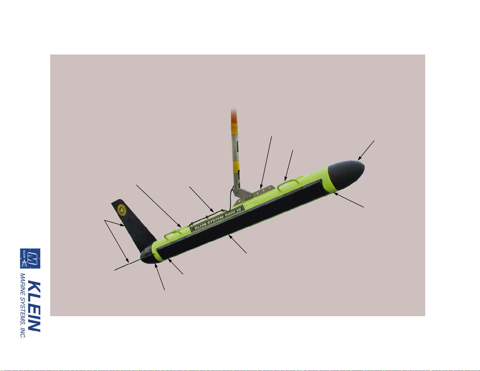
Starboard transducer array
Tow bracket
Safety cable
Carrying
handle (4)
Tail cone
Stabilizing fins
Nose cone
Stainless steel
towfish housing
Safety cable
tab
Altimeter
System Components 1-3
Figure 1-1: Series 5000 Towfish
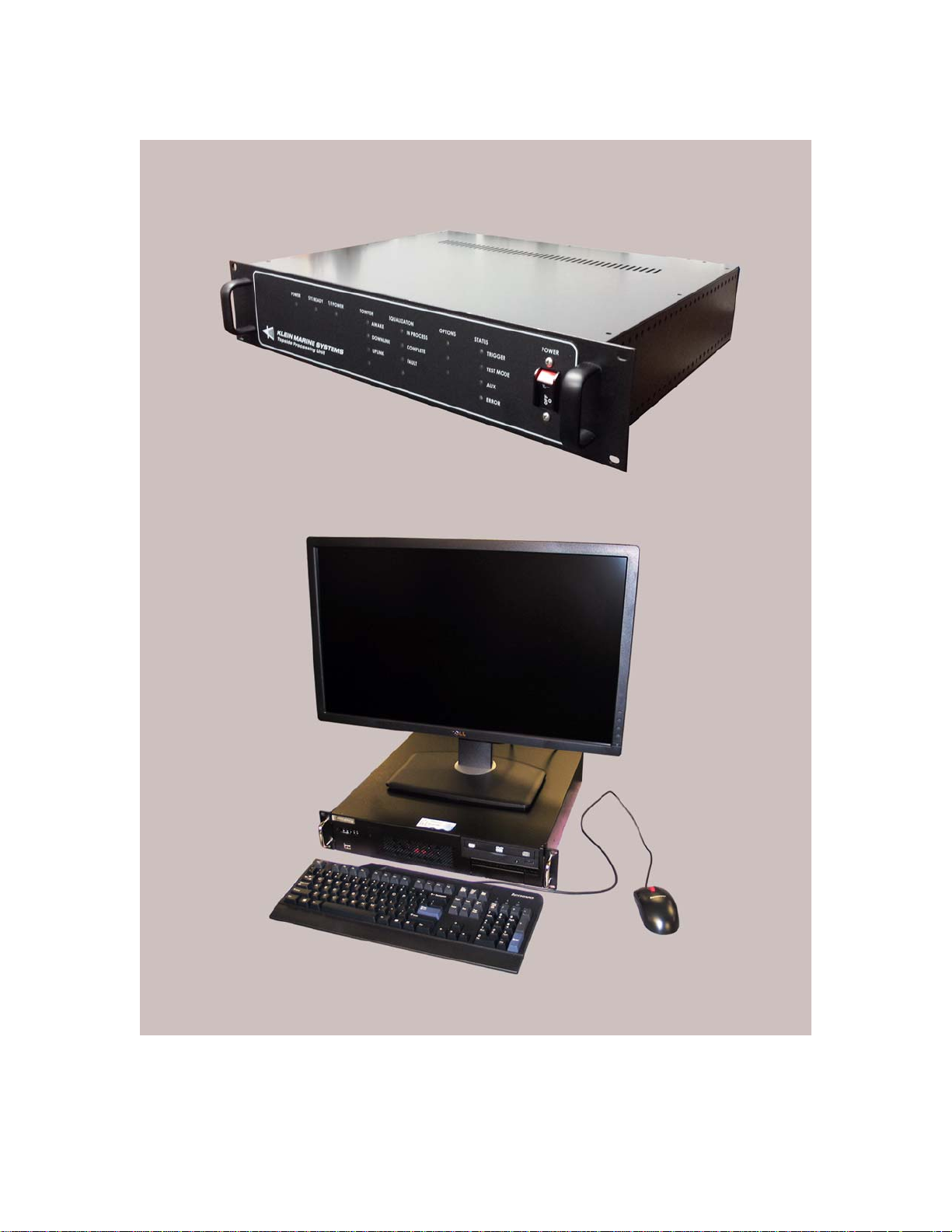
1-4 CHAPTER 1 Overview
SonarPro Workstation
Transceiver and Processing Unit (TPU)
Figure 1-2: Series 5000 V2 Sonar System Topside System Main Components
Series 5000 V2 Sonar System Operations and Maintenance Manual P/N 11214512, Rev. 04

System Components 1-5
commands to the towfish by combining 200 VDC with FSK control signals for
transmission over the coaxial conductor in the tow cable. In addition, the TPU
initiates each ping cycle to the side scan sonar and provides a trigger signal
simultaneously with the responder trigger generated in the towfish for use with an
acoustic positioning system. The TPU can also input standard National Marine
Electronics Association (NMEA) 0183 message sentence formats from a
connected GPS, and a 1 PPS input is provided which inputs 1 PPS (one pulse per
second) signals from the GPS. This signal is used in conjunction with a NMEA
$ZDA message input to add an accurate time stamp to the data.
1.2.3 SonarPro Workstation
The SonarPro Workstation is an industrial grade based computer housed in a
19-inch rack mountable 2U chassis that inputs processed and time tagged sonar
and sensor data from the TPU over an Ethernet 100baseT connection. A SATA
hard drive is included with the W indows operating system and SonarPro installed.
SonarPro is a comprehensive Windows based software program that provides
multiple displays of real-time or previously recorded sonar and sensor data.
SonarPro also allows you to record all acquired sonar and sensor data. The
SonarPro Workstation includes a high resolution 27-inch 2560 x 1440 monitor, a
keyboard and a mouse.


CHAPTER 2: SPECIFICATIONS
This chapter includes the physical and performance specifications for the main
components of the Series 5000 V2 Sonar System.
NOTE Specifications are typical and subject to change without notice.
2.1 Sonar System
Beams: 5 port and 5 starboard
2-1
Sonar frequency: 455 kHz
Maximum range: Up to 150 m per side (actual range varies
with environmental conditions and pulse
length)
Range scales: 50, 75, 100, and 150 m; 50 and 75 m are
high resolution; 200 and 250 m
reconnaissance mode
Swath width: 100 to 500 m (usable swath width varies
with environmental conditions and pulse
length)
Along track resolution: 10 cm @ 38 m, 20 cm @ 75 m and
36 cm @ 150 m
Across track resolution: 3.75 cm
Operating speed envelope: 2 to 10 knots at 150 m
Depth rating: 500 m (1640 ft)
200 m (656 ft) with bathymetry option
Operating temperature: -2–35C (14–95F)

2-2 CHAPTER 2 Specifications
2.2 Topside System
The main topside components of the Series 5000 V2 Sonar System are the
Transceiver and Processing Unit (TPU) and the SonarPro Workstation.
2.2.1 System Power Requirements
The system power requirements are 100–125 or 200–250 VAC, 50–60 Hz at
100 watts for the TPU and the towfish together.
2.2.2 TPU
Size: 8.9 cm (3.5 in.) H
Weight: 7.6 kg (17 lb)
Chassis type: 2U, 19-inch rack mount
48.3 cm (19.0 in.) W
35.6 cm (14.0 in.) D
I/O ports: (1) LAN
(4) RS-232
(4) BNC
(1) RJ45 debug
(1) N-Type
2.2.3 SonarPro Workstation
Size: 8.9 cm (3.5 in.) H
48.3 cm (19.0 in.) W
43.2 cm (17.0 in.) D
Weight: 22.8 kg (50 lb)
Chassis type: 2U, 19-inch rack mount
CPU: Intel Pentium Dual Core
Memory: 8 GB
Storage: SATA hard drive
DVDRW optical drive
I/O ports: (2) Ethernet 10/100/1000baseT
(6) USB 2.0
(2) RS-232
(1) VGA
(1) DVI (dual display support)
Operating system: Windows
Series 5000 V2 Sonar System Operations and Maintenance Manual P/N 11214512, Rev. 04

Monitor: 27-inch diagonal
Operator I/O: Keyboard and mouse
2.3 Towfish
2.3.1 General
Body material: Type 316 stainless steel
Nose/tail cone material: Urethane (80 D Durometer)
Tail fin material: Hard-coat anodized 6061 aluminum
Size: 203 cm (79.9 in.) long
Towfish 2-3
2560 x 1440 resolution
16:9 aspect ratio
16.8 cm (6.6 in.) diameter
30.5 cm (24 in.) wide, including tail fins
61.0 cm (24 in.) high, including tail fins
Weight in air: 70.5 kg (155 lb)
Weight in water: 47.7 kg (105 lb)
2.3.2 Transducers
Type: Proprietary line array
Vertical beam angle: 40°
Depth limit: 500 m (1640 ft)
200 m (656 ft) with bathymetry option
2.3.3 Transmitter
Type: Toneburst
Transmission pulse: 25, 50 and 100 µsec CW; 200 µsec
2-tone; 2, 4, 8 and 16 msec chirp
2.3.4 Receiver
Type: High gain, tuned preamplifier with TVG
Noise figure: 1 dB nominal
TVG range: 80 dB

2-4 CHAPTER 2 Specifications
2.3.5 A/D Converter
Type: Pipeline
Resolution: 14 bits
Quantization: Linear
Sample rate: Proprietary
2.3.6 Multiplexer
Modulation format: Pulse code modulation (PCM)
Multiplexing format: Time division multiplexing (TDM)
Number of channels: 32
Data rate: 29.12 Mbaud
Data format: NRZ
Bit error rate: Better than 1x10
-8
(before correction)
2.3.7 Power
Input power: Powered from the TPU; no additional
power required
2.3.8 Heading Sensor
Accuracy level: ±0.5 RMS
Accuracy tilted: ±1.0 RMS
Resolution: 0.1
Repeatability: ±0.1
2.3.9 Pitch and Roll Sensor
Accuracy: ±0.2 RMS
Resolution: 0.1
Repeatability: ±0.2
2.3.10 Pressure Sensor
Pressure range: 0–750 psig
Accuracy: ±0.10%
Series 5000 V2 Sonar System Operations and Maintenance Manual P/N 11214512, Rev. 04

2.4 Tow Cables
Electrically, the tow cable must be 50 ohms. The whole cable assembly, including
the deck cable, the slip rings, the winch, the tow cable, and the connectors must be
coax all the way from the TPU to the towfish.
2.4.1 Lightweight Coaxial Deck Cable
Type: Polyurethane jacketed, coaxial Kevlar
Conductors: Coaxial copper
Diameter (OD): 1.15 cm (0.455 in.)
Voltage rating: 600 VDC
2.4.2 Armored Coaxial Tow Cable (0.40)
Type: Double layer, counter helical, galvanized
Tow Cables 2-5
reinforced
improved plow steel (GIPS)
Stainless steel can be a special order
Conductors: Coaxial copper
Diameter (OD): 10.2 mm (0.40 in.)
Breaking strength: 4990 kg (11, 000 lb)
Working load: 1247 kg (2750 lb)
Operational length (including
deck cable):
Voltage rating: 1200 VDC
Termination: Stainless steel shackle at towfish end
400 m max
2.4.3 Armored Coaxial Tow Cable (0.68)
Type: Double layer, counter helical, galvanized
extra improved plow steel (GEIPS)
Stainless steel can be a special order
Conductors: Coaxial copper
Diameter (OD): 17.3 mm (0.68 in.)
Breaking strength: 18140 kg (40,000 lb)
Working load: 4535 kg (10,000 lb)

2-6 CHAPTER 2 Specifications
Operational length (including
deck cable):
Voltage rating: 3000 VDC
Termination: Stainless steel shackle at towfish end
2.5 Towfish Options
The towfish can be equipped with the following options:
• Responder interface
• Transponder interface
• Magnetometer interface
• Yaw rate sensor
• Altimeter
750 m max
• Depressor wings
2.6 Tow Cable Options
Two types of tow cables are available:
• Armored coaxial (0.40)
• Armored coaxial (0.68)
Series 5000 V2 Sonar System Operations and Maintenance Manual P/N 11214512, Rev. 04

CHAPTER 3: PREPARATION FOR USE
This chapter provides instructions for unpacking the Series 5000 V2 Sonar
System, connecting its components and a navigation system, and testing the
system both on deck and at sea. Descriptions of all the connections and the
controls and indicators for all the system components are also included.
3.1 Unpacking and Inspection
The towfish and the topside system components, including associated cables and
documentation, are shipped in multiple shipping cases. Unpack all of the cases and
verify that all of the items listed on the packing list have been received. If any
items are damaged or missing, immediately contact Klein Marine Systems, Inc. or
your KMS sales representative. In addition, record the serial numbers for the
towfish, the TPU and the SonarPro Workstation. The towfish serial number can be
found on the towfish tow bracket. Refer to Figure 1-1 on page 1-3 for the location
of the tow bracket. The serial numbers for the TPU and the SonarPro Workstation
or laptop can be found on the rear panel of each.
3-1
3.2 Locating the Topside System Components
The TPU and the SonarPro Workstation should be located in an area that is
protected from weather and spray and where the temperatures are consistently
between 0°C and 35°C (32°F and 95°F). The location should also be near the
towfish launch point or be adequately equipped with devices for communicating
with launch personnel. If separately mounting components in a 19-inch rack,
ensure that the rack is properly secured and that there is ample room behind it for
connecting the cables. A thick layer of foam should also be placed under the rack
for shock isolation, and the back of the rack should be left open for proper air flow .
Support the units inside the rack using appropriate mounting brackets, shelves or
slides as needed and secure the front panels to the front of the rack where possible
using standard 19-inch rack front panel mounting hardware.
3.3 Power Requirements
The TPU and the SonarPro Workstation require 100–125 or 200–250 VAC,
50–60 Hz power to operate. The Series 5000 V2 Sonar System is designed to
protect against over and under voltage and transient spikes. However, it is always
best to check the power source carefully using a voltmeter or oscilloscope before
operating the equipment.

3-2 CHAPTER 3 Preparation for Use
CAUTION Application of improper AC power may damage the Series
5000 V2 Sonar System. Do not turn the equipment on until the supply
voltage and frequency have been checked.
Since a variety of power connectors are in use throughout the world, it may be
necessary to use an adapter or to cut off the US-type plug on the AC power cable
and re-terminate it with a new plug. Should this modification be required, the
wires should be connected in accordance with Table 3-1.
Table 3-1: TPU Power Cable Wiring
COLOR FUNCTION
Green Ground (earth)
Blue or white Neutral
Brown or black Hot
3.3.1 Grounding
It is important that the Series 5000 V2 Sonar System be well grounded to minimize
potential hazards to the operator and electrical interference from other equipment.
A good ground for the system is a low impedance, well conducted path to sea
water. Always check the quality of the electrical ground by verifying that the AC
power source ground has no voltage potential with respect to the vessel hull.
3.3.2 TPU and SonarPro Workstation Circuit Breakers
The main AC power input line is protected by a switch/circuit breaker in both the
TPU and the SonarPro Workstation. The one on the TPU is located on the front
panel on the far right as shown in Figure 3-3 on page 3-12. The one on the
SonarPro Workstation is located on the back panel just to the right of the AC
INPUT connector as shown in Figure 3-2 on page 3-9. To reset a switch/circuit
breaker, switch it to ON.
3.4 Towfish Setup
Before connecting the tow cable, make a general inspection of the towfish. Check
that the retaining screws securing the towfish nose cone and tail section assemblies
are tight. Check the tail fins and tow bracket assembly to be sure the retaining
screws and bolts are secure. Also verify that the tail fins are straight and true.
Series 5000 V2 Sonar System Operations and Maintenance Manual P/N 11214512, Rev. 04

Towfish Setup 3-3
3.4.1 Connecting the Tow Cable
WARNING Before connecting the tow cable, verify that the power to the
TPU is turned off. Also disconnect the TPU power cable from the power
source. Failure to follow this practice may result in personal injury or
damage to the towfish or the TPU electronics, or to both.
SHOCK HAZARD Do not connect or disconnect the tow cable from the
towfish or the TPU when power is on. Failure to follow this practice may
result in personal injury and will damage the towfish or the TPU
electronics, or both.
To connect the tow cable:
1. Remove the retaining ring from the beveled end of the tow pin and withdraw
the pin from the tow bracket.
2. Align the tow shackle mounting hole with the upper mounting hole of the tow
bracket, and then insert the beveled end of the tow pin through the holes in the
tow cable shackle and the bracket and secure the pin with the retaining ring.
3. Remove the dummy plug from the connector on the towfish end of the tow
cable and from the towfish jumper cable.
CAUTION Always avoid putting excessive silicon grease on the Subcon
male pins. Apply a light coat of grease, and never put gr ease into the female
connectors.
4. Apply a thin film of silicone grease to the pins of the male connector. Use a
high quality, nonconducting grease such as Dow Corning DC-4.
CAUTION When connecting or disconnecting the electrical connection, do
not bend it back and forth. Use straight up action. Pull on the connector,
not the cable.
5. Align the male and female connectors and press the connectors together
firmly . If neces sary, use a slight side to side rocking motion while pressing on
the connector, but do not bend the pins. When properly inserted there should
be no gap between the surfaces of the two connectors.

3-4 CHAPTER 3 Preparation for Use
6. Attach the shackle end of the safety cable to the bail grip loop on the tow cable
near the tow cable shackle, and the clevis pin end to the safety cable tab on the
top of the towfish near the tail. Refer to Figure 1-1 on page 1-3 for the location
of the safety cable tab. The safety cable must be taut enough so that drag, or
the likelihood of snagging, is not increased, but loose enough so that it does
not interfere with the functioning of the tow shackle.
NOTE The tow cable and not the safety cable must take up the strain of the
tow load.
7. If not already secured, use cable ties (7.5 x 0.185 in.), which are included in
the towfish spares kit, to fasten the safety cable to the cable hold-down clips
on the top of the towfish housing. Place a cable tie through the shackle pin
hole and wrap around the shackle pin to prevent the shackle from loosening.
Use electrical tape every 30 cm (12 in.) to secure the safety cable to the tow
cable starting at the top of the tow shackle and up the bail grip loop. Move the
tow shackle forward and backward to check for smooth operation.
3.4.2 Connecting the Tow Cable with the Optional K-Wing Depressor
The shackle on the tow cable connects mechanically to the towfish K-Wing
depressor tow bracket using a tow pin. The depressor connects mechanically to the
towfish. The waterproof connector on the towfish jumper cable connects to the
waterproof connector on the tow cable. The towfish mechanical and electrical
connection procedure is as follows:
1. Remove the retaining ring from the beveled end of the tow pin, withdraw the
pin from the tow bracket and set it aside. Remove the two bolts and tow
brackets from the welded-on six-hole towing flange. Take note of the location
of the tow brackets for future reference.
2. Position the K-Wing depressor over the towing flange in the same location as
where the tow brackets were previously connected. Secure the depressor to the
towing flange with the fasteners provided.
3. Align the tow shackle mounting hole with the mounting hole of the K-Wing
shackle on the tow depressor tow bracket. Insert the beveled end of the tow
pin through the holes in the tow cable shackle and the bracket, and secure the
tow pin with the retaining ring.
4. If the towfish was previously configured for towing without a depressor, it
will be necessary to extend the free length of the towfish 100-inch jumper
cable in order to reach the shackle connector. Do not extend more than is
Series 5000 V2 Sonar System Operations and Maintenance Manual P/N 11214512, Rev. 04

Towfish Setup 3-5
needed to make the connection and to provide free rotation of the tow shackle.
Remove the dummy plug from the connector on the end of the tow cable.
Apply a thin film of silicone grease to the pins of the connector. Do not over
grease. Align the male and female connectors, and press the connectors
together firmly. If necessary, use a slight side-to-side rocking motion while
pressing on the connector, but do not bend the pins. When properly inserted
there should be no gap between the surfaces of the two connectors.
5. Attach the shackle end of the safety cable to the bail grip loop on the tow cable
near the tow cable shackle, and the clevis pin end to the safety cable tab on the
top of the towfish near the tail. Refer to Figure 1-1 on page 1-3 for the location
of the safety cable tab. The safety cable must be taut enough so that drag, or
the likelihood of snagging, is not increased, but loose enough so that it does
not interfere with the functioning of the tow shackle.
NOTE The tow cable and not the safety cable must take up the strain of the
tow load.
6. If not already secured, use cable ties (7.5 x 0.185 in.), which are included in
the towfish spares kit, to fasten the safety cable to the cable hold-down clips
on the top of the towfish housing. Place a cable tie through the shackle pin
hole and wrap around the shackle pin to prevent the shackle from loosening.
Use electrical tape every 30 cm (12 in.) to secure the safety cable to the tow
cable starting at the top of the tow shackle and up the bail grip loop. Move the
tow shackle forward and backward to check for smooth operation.
3.4.3 Disconnecting the Tow Cable from the Towfish
If possible, it is best to keep the tow cable connected to the towfish while on deck.
If the tow cable is disconnected, however, it is very important that all the
connectors be properly maintained. Connectors must be kept clean and must
remain out of the way of traffic while on deck. Klein Marine Systems, Inc.
supplies dummy connectors which can be used to protect the underwater
connectors on the towfish and cable when they are not mated to each other.
WARNING Before disconnecting the tow cable, verify that the TPU is
turned off and that its power cord is disconnected. Failure to follow this
practice may result in personal injury or damage to the towfish or to the
TPU electronics, or to both. For the location of the power switches, refer to “Topside
System Controls and Indicators” on page 3-11.

3-6 CHAPTER 3 Preparation for Use
To disconnect the tow cable:
1. Verify that the TPU is switched off and that its power cord is disconnected.
2. Disconnect the safety cable from the bail grip loop. Remove the electrical tape
securing the safety cable to the tow cable. Cable ties fastening the safety cable
to the cable hold-down clips on the towfish housing may remain in place.
3. Separate the connectors by first loosening the locking sleeve. Then double
check that the TPU is off and grasp the body of the connector and gently pull
it out of the tow shackle connector. Do not pull on the wires to separate the
connectors. Always hold the body of the connector. After separating the
connectors, put a thin coating of silicone grease on the rubber section of the
connector pins.
4. Remove the retaining ring from the tow pin and withdraw the pin. Disengage
the tow cable shackle from the towfish or tow bracket. Replace the tow pin in
the hole in the tow bracket, and secure it with the retaining ring.
3.5 Topside System Connections
All of the topside system components connect together using the supplied cables.
User supplied cables are required for connecting to a GPS and to other equipment.
3.5.1 TPU Connections
All the connections to the TPU are made to connectors on the back panel which is
shown in Figure 3-1.
The TPU connectors are the following:
LAN: RJ-45 connector that connects to the ETHERNET
connector on the SonarPro Workstation.
COM A: DB9 male RS-232 serial port connector that is for
factory use only.
COM B: DB9 male RS-232 serial port connector that is
available as a spare and is not used.
COM C: DB9 male RS-232 serial port connector that is
available as a spare and is not used.
NAV: DB9 male RS-232 serial port connector that
connects to a shipboard navigation system and
inputs NMEA 0183 message sentence formats.
EXT TRIG IN: Not supported for this system.
Series 5000 V2 Sonar System Operations and Maintenance Manual P/N 11214512, Rev. 04

TOWFISH connector
NOTE: Connectors that are not
called out are not used or are
for factory use only.
NAV connector
AC INPUT connector
1 PPS IN connector
T/F TRIG connector
TRIG A connector
LAN connector
Figure 3-1: TPU Back Panel
Topside System Connections 3-7

3-8 CHAPTER 3 Preparation for Use
T/F TRIG:
BNC connector that connects to an external sonar
system and is used to trigger the sonar of that system
at the start of each ping cycle. Provides a TTL
compatible, 100-µs wide output pulse.
TRIG A: BNC connector that connects to an ultra short
baseline navigation system (USBL). Provides a TTL
compatible, 100-µs wide output pulse with each
trigger of the optional responder.
1 PPS IN: BNC connector that is used to input 1 PPS (one
pulse per second) signals.
TOWFISH: Type N coaxial connector that connects to the
towfish using a deck cable or a tow cable.
AC INPUT: IEC type connector that connects to the AC power
source.
3.5.2 SonarPro Workstation Connections
All the connections to the SonarPro Workstation are made to connectors on the
back panel which is shown in Figure 3-2.
The SonarPro Workstation connectors are the following:
USB: USB connectors (4, plus 2 on the front panel). Any
two connect to the keyboard and the mouse. The
front panel USB connectors are shown in Figure 3-4
on page 3-14.
DVI: DVI connector that connects to the monitor.
ETHERNET: RJ-45 connectors (2). Any one connects to the LAN
connector on the TPU.
AC INPUT: IEC type AC input connector that connects to the
AC power source.
Series 5000 V2 Sonar System Operations and Maintenance Manual P/N 11214512, Rev. 04

ON/OFF switch
AC INPUT connector
ETHERNET connector (2)
USB connector (4)
NOTE: Connectors that are not
called out are not used or are
available for optional use.
DVI connector
and circuit breaker
Topside System Connections 3-9
Figure 3-2: SonarPro Workstation Back Panel

3-10 CHAPTER 3 Preparation for Use
3.6 Connecting the Topside System Components
The following cables are required to connect the TPU and the SonarPro
Workstation:
• Ethernet cable
• AC power cords (2)
• Deck cable or tow cable (deck cable is optionally supplied)
WARNING Before connecting the topside system components, verify that
the TPU is turned off and that its power cord is disconnected. Failure to
follow this practice may result in personal injury or damage to the towfish
or to the TPU electronics, or to both. For the location of the power switches, refer to
“Topside System Controls and Indicators” on page 3-17.
To connect the TPU and the SonarPro Workstation:
1. Connect the Ethernet cable to the LAN connector on the TPU and to either
one of the two the ETHERNET connectors on the SonarPro Workstation.
2. Connect the monitor to the DVI connector on the SonarPro Workstation and
connect the monitor power supply to the AC power source.
3. Connect the keyboard and the mouse to any two of the six USB connectors on
the SonarPro Workstation.
4. Connect a GPS to the NAV connector on the TPU. A user supplied RS-232
serial cable is required where one end is terminated with a DB9 female
connector and the other end is as required by the navigation system.
5. Verify that the GPS is outputting NMEA-0183 formatted data strings at
4800 baud, no parity , 8 data bits, and 1 stop bit. In addition, the GPS should be
outputting the following messages:
• GLL or GGA
•VTG
• RMC (optional)
NOTE If 4800 baud is not available from the GPS, contact KMS customer
service for instructions on how to reconfigure the system to accept a
different baud rate. Refer to “Customer Service” on page xvi for
information on how to contact KMS customer service.
Series 5000 V2 Sonar System Operations and Maintenance Manual P/N 11214512, Rev. 04

Topside System Controls and Indicators 3-11
6. Connect the optional deck cable or tow cable to the TOWFISH connector on
the TPU.
NOTE For the predeployment checks, the optional deck cable can be
temporarily connected to the TOWFISH connector on the TPU and to the
towfish.
7. Connect an AC power cable to the AC INPUT connectors on the TPU and the
SonarPro Workstation and to the AC power source.
The following connections are optional:
8. Connect the 1 PPS IN connector on the TPU to the 1 PPS source. A user
supplied BNC-to-BNC cable is required.
9. Connect the T/F TRIG connector on the TPU to the trigger input of an
external sonar system. A user supplied BNC-to-BNC cable is required.
10. Connect the TRIG A connector on the TPU to the trigger input of a USBL
system. A user supplied BNC-to-BNC cable is required.
3.7 Topside System Controls and Indicators
The TPU and the SonarPro Workstation include controls and indicators on the
front panels. The SonarPro Workstation also has its power switch on the back
panel.
3.7.1 TPU Controls and Indicators
All of the TPU controls and indicators are on the TPU front panel which is shown
in Figure 3-3.
The TPU controls and indicators are the following:
POWER switch: Rocker switch/circuit breaker that turns the TPU on
or off and provides AC input current protection.
Should the breaker trip, the switch/circuit breaker
will switch to the OFF position. To reset it, switch it
to the ON position.
POWER: Green LED that is on when the TPU is powered.
SYS READY: Green LED that will flash while the TPU and the
towfish are powering up and then remain on when
the TPU is ready to link with SonarPro on the
SonarPro Workstation.

Series 5000 V2 Sonar System Operations and Maintenance Manual P/N 11214512, Rev. 04
POWER indicator
SYS READY indicator
T/F POWER indicator
TOWFISH indicators
POWER switch
STATUS indicators
NOTE: Indicators that are not
called out are not used or are
available for optional use.
3-12 CHAPTER 3 Preparation for Use
Figure 3-3: TPU Front Panel

Topside System Controls and Indicators 3-13
T/F POWER: Blue LED that is on when power is being applied to
the towfish.
TOWFISH AWAKE: Green LED that is on when the towfish is powered
and is acquiring data.
TOWFISH DOWNLINK: Green LED that is on when commands are being
transfered from the TPU to the towfish.
TOWFISH UPLINK: Green LED that is on when data are being transfered
from the towfish to the TPU.
STATUS TRIGGER: Yellow LED that flashes when the sonar on the
towfish transmits.
STATUS RESPONDER: Yellow LED that flashes when a responder trigger is
sent to the towfish.
STATUS ERROR: Red LED that flashes if system errors are detected.
3.7.2 SonarPro Workstation Controls and Indicators
Most of the SonarPro Workstation controls and indicators are on the SonarPro
Workstation front panel which is shown is Figure 3-4. Also shown is the location
of the DVDRW optical drive.
The SonarPro Workstation controls and indicators are the following:
ON/OFF switch: Rocker switch/circuit breaker that switches AC
power to the SonarPro Workstation and provides AC
input current protection. This switch/circuit breaker ,
which is on the back panel and is shown in
Figure 3-2 on page 3-9, should be left in the ON
position. Should the breaker trip, the switch/circuit
breaker will switch to the OFF position. To reset it,
switch it to the ON position.
HARD DRIVE ACTIVITY: Green LED that flashes when the hard drive is being
accessed.
ETHERNET: Green LED that flashes when there is activity on
Ethernet port.
POWER: Blue LED that is on when the SonarPro Workstation
is on.
POWER switch: Push button switch that turns the SonarPro
Workstation on or off.
RESET switch: Push button switch that resets the SonarPro
Workstation.

Series 5000 V2 Sonar System Operations and Maintenance Manual P/N 11214512, Rev. 04
HARD DRIVE ACTIVITY indicator
POWER ON indicator DVDRW optical drive
ETHERNET indicator
RESET switch
POWER switch
USB connector (2)
3-14 CHAPTER 3 Preparation for Use
Figure 3-4: SonarPro Workstation Front Panel

System Activation and Test 3-15
3.8 System Activation and Test
The Series 5000 V2 Sonar System should be activated and tested on deck and at
sea before starting an actual survey.
NOTE Should it be required to change the IP address, edit the startup.ini
file or update the software of the TPU, refer to APPENDIX C: “Configuring
and Updating the TPU.”
3.8.1 Activating and Testing the System on Deck
To activate and test the system on deck:
1. Verify that the towfish has been properly set up and the system components
connected.
2. Turn on the navigation system and let it acquire its location.
3. Verify that the tow cable is connected to the towfish and to the TPU or to the
SP-III TPU.
4. Turn on the SonarPro Workstation or the laptop computer and wait for the
Windows desktop to appear.
5. Turn on the TPU.
After 10 seconds the POWER indicator should turn on and the SYS READY
indicator should flash. After approximately 1 minute the SYS READY and
AWAKE indicators should turn on, the DOWNLINK and TRIGGER
indicators should flash, and the TF POWER should be on.
CAUTION Serious damage to the towfish electronics may occur if the
towfish is operated on deck for periods longer than fifteen minutes.
Between periods of operation, let the sonar cool for fifteen minutes. In high
temperature climates, protect the towfish from direct exposure to the sun prior to and
during operation.
6. Start SonarPro and observe that the towfish is operational by viewing the
waterfall sonar data in the Sonar Viewer window. Also check that sensor data
are being displayed in the Information window.
7. If a GPS is connected, check that navigation data are being displayed in the
Information window.
8. Select the 150-meter range and allow the TVG to normalize; it will take about
two minutes.

3-16 CHAPTER 3 Preparation for Use
9. Perform a rub test on the port and starboard transducers to confirm that the
receivers are operating properly. Do this test by vigorously rubbing each
transducer, one at a time, while observing the Sonar Viewer window in
SonarPro for returns.
10. Exit SonarPro and turn off the SonarPro Workstation and the TPU.
3.8.2 Activating and Testing the System at Sea
To activate and test the system at sea:
1. Verify that the towfish has been properly set up and the system components
connected.
2. Turn on the navigation system and let it acquire its location.
3. Verify that the tow cable is connected to the towfish and to the TPU.
4. Turn on the SonarPro Workstation and wait for the Windows desktop to
appear.
5. Turn on the TPU.
After 10 seconds the POWER indicator should turn on and the SYS READY
indicator should flash. After approximately 1 minute the SYS READY and
AWAKE indicators should turn on, the DOWNLINK and TRIGGER
indicators should flash, and the TF POWER should be on.
CAUTION Serious damage to the towfish electronics may occur if the
towfish is operated on deck for periods longer than fifteen minutes.
Between periods of operation, let the sonar cool for fifteen minutes. In high
temperature climates, protect the towfish from direct exposure to the sun prior to and
during operation.
6. Start SonarPro and observe that the towfish is transmitting by viewing the
output pulse in the Sonar Viewer window. Also check that sensor data are
being displayed in the Information window.
7. If a GPS is connected, check that navigation data are being displayed in the
Information window.
8. Deploy the towfish.
CAUTION When the towfish is close to the sea floor, the bottom tracking
(altitude) performance is less accurate. Exercise extreme caution when
operating the towfish at altitudes of less than 4 meters (13 feet).
Series 5000 V2 Sonar System Operations and Maintenance Manual P/N 11214512, Rev. 04

System Activation and Test 3-17
9. Adjust the towfish within the water column so that it is at a safe altitude off
the bottom and under the boat wake (about 15 percent of range). A good
starting vessel speed is 4–5 knots. Check for the following:
• The image is satisfactory.
• Pitch, roll, depth, and altitude are being displayed.
• Speed and heading are being displayed from the navigation system.
10. Refer to the SonarPro User Manual (P/N 11210093) for instructions on how to
operate SonarPro to acquire, display and record sonar data.


CHAPTER 4: MAINTENANCE AND
TROUBLESHOOTING
This chapter provides instructions on how to perform maintenance and
troubleshooting of the Series 5000 V2 Sonar System and includes guides for
taking care of the equipment on a daily, weekly, and long term basis. In addition,
instructions are provided on how to replace the fixed tail cone assembly and
remove, install and test the towfish electronics.
WARNING Klein Marine Systems, Inc. recommends all tr oublesh ooting be
done by a trained technician. Some circuits in the Sonar Transceiver and
Processing Unit have voltages as high as 240 volts, and some cir cuits in the
sonar towfish have 1500 volts. You should familiarize yourself with the location of
these voltages before you attempt any troubleshooting. Failure to observe these
warnings could result in injuries to personnel.
4-1
CAUTION Serious damage to the sonar electronics may occur if the sonar
towfish is operated out of the water for periods longer than 15 minutes. Let
the sonar cool 15 minutes or longer between operations. Protect the sonar
towfish from direct exposure to the sun prior to and during operation in high
temperature climates.
4.1 General Maintenance Recommendations
Equipment used at sea is subjected to severe environmental and handling
conditions. While the Series 5000 V2 Sonar System is designed to operate in such
conditions, a certain amount of routine maintenance is necessary to ensure trouble
free, long term operation.
Keep a maintenance log. This provides assistance in tracking what has or has not
been done with the system. A log is useful when tracking problems, if they do
occur, and is especially important if more than one TPU, SonarPro Workstation or
towfish is used in a large survey operation. Inventory the system, related spares
and accessories carefully. Record the serial numbers of the major components.
Store the shipping boxes in a safe place so they can be reused when needed. A
small amount of regular maintenance and care makes the critical difference in a
successful field operation. The following pages contain the recommended routine
checking and maintenance schedules for a daily, weekly, and long term basis.

4-2 CHAPTER 4 Maintenance and Troubleshooting
4.2 Maintenance Checklists
4.2.1 Daily Maintenance Checklist
Perform the following maintenance steps at the end of each day’s operation:
1. Turn off the power to the TPU and to the SonarPro Workstation.
2. Verify that all cables and connectors are secure and tightened.
3. If fresh water is available, wash down the towfish and towing apparatus. Cover
them while not in use to protect against salt water spray and to minimize
corrosion.
4. Keep the tow cable plugged into the towfish, or use dummy plugs on the tow
cable and towfish to keep the connectors from exposure to the salt atmosphere.
Remember to put a thin film of silicone grease, such as Dow-Corning 4, on the
rubber portion of the underwater connector every time the towfish is
disconnected. Avoid getting too much grease on the metal pins of the connector; a
very light coating is sufficient.
5. Check that all of the screws on the towfish are tight.
4.2.2 Weekly Maintenance Checklist
Perform the following maintenance steps at the end of each week’s operation:
1. Turn off the power to the TPU and to the SonarPro Workstation.
2. Check all cables for abrasion and damage. If any wear spots are noticed, clean
them with fresh water, dry them, and wrap them carefully with electrical tape,
such as Scotch #88 or #33. If there is wear or fraying in any of the cables in an
area subject to high tension, repair or replace the cable.
3. Inspect and clean the system plugs and jacks.
4. Inspect the towfish for signs of corrosion or other damage.
5. Check the underwater connectors on the towfish. The contacts should be clean
and shiny . Contacts may be cleaned with a rubber pencil eraser or very fine emery
paper.
4.2.3 Long Term Maintenance Checklist
Perform the following maintenance steps at six month intervals, or more
frequently when continued long term usage is occurring.
1. Turn off the power to the TPU and to the SonarPro Workstation.
Series 5000 V2 Sonar System Operations and Maintenance Manual P/N 11214512, Rev. 04

Replacing the Fixed Tail Cone Assembly 4-3
Figure 4-1: Towfish Tail with Rear Center Pin
in Place
2. Thoroughly clean the TPU, cables and towing equipment. Clean the top and
outside surfaces of the TPU using a cloth dampened with fresh water. Use a small
amount of detergent if necessary. Do not let dirt and salt deposits accumulate on
the TPU cabinet.
3. Remove the screws securing the nose cone of the towfish and check that the
connectors are firmly seated. Use a thin film of silicone grease on all external
connectors. Make sure the transducer leads are free from cuts or abrasion.
4. Follow the instructions in the manufacturer's manual for any necessary cleaning
and maintenance of the SonarPro Workstation.
4.3 Replacing the Fixed Tail Cone Assembly
The following procedure
describes how to install or
replace the fixed tail cone
assembly , P/N 14105284, used
on the towfish. This assembly
is installed on all new Series
5000 V2 towfish and can be
retrofitted on older Series 5000
V2 towfish using the collision
tolerant tail cone assembly.
The following tools and parts
are required:
• 8-mm hex key with a shaft
at least 6 in. (15 cm) long
• Medium flat bladed screwdriver
•Pliers
• Tail cone assembly (P/N 14105284)
Also refer to Drawing 15100952, Option Kit, .25" Tailfin, "T", System 5000
throughout the procedure.
To replace the fixed tail cone assembly:
1. Align rear center pin. This center pin is not part of the tail cone assembly and
is used with both the older collision tolerant tail cone and the new fixed tail
cone assembly.

4-4 CHAPTER 4 Maintenance and Troubleshooting
Figure 4-2: Tail Cone being Aligned and
Attached to Towfish
Figure 4-3: Tail Cone Being Tightened with Hex
Key
2. With the large hole to the
upper right, align the tail
cone with the rear center
pin and thread the rear tail
cone bolt (7) into the rear
center pin using the 8-mm
hex key.
3. Using the pliers, tighten the
rear tail cone bolt (7). Do
not overtighten.
Series 5000 V2 Sonar System Operations and Maintenance Manual P/N 11214512, Rev. 04

Replacing the Fixed Tail Cone Assembly 4-5
Figure 4-4: Crossbar Used to Secure Tail Cone
Parts
Figure 4-5: Tail Cone Being Tightened With
Screwdriver and Key
4. Install the crossbar (4) into
the large hole.
5. Using the flat bladed screw
driver, align the threaded
hole in the crossbar (4) and
screw the bolt (7) with the
retaining cup (5) into the
crossbar with the 8-mm hex
key. Leave the retaining
cup loose to accommodate
the tail fins.

4-6 CHAPTER 4 Maintenance and Troubleshooting
Figure 4-6: Tail Fins being Inserted into Tail
Cone
Figure 4-7: Tail Fins being Secured to Tail
Cone
6. Install the two horizontal
tail fins (2) and the vertical
tail fin (3) by inserting the
forward slot into the
towfish body . The rearward
slot should be secured by
the retaining cup.
7. Tighten the retaining cup
bolt (7) so that the tail fins
are secured.
4.4 Removing the Fixed Tail Cone Assembly
Removal of the fixed tail cone assembly is the reverse of the installation
procedure.
Series 5000 V2 Sonar System Operations and Maintenance Manual P/N 11214512, Rev. 04

Removing the Towfish Electronics 4-7
Figure 4-8: Push/Pull Assembly
Figure 4-9: Jacking Screw
4.5 Removing the Towfish Electronics
To remove the towfish
electronics:
1. Remove the towfish nose
cone by unscrewing the
socket head cap screw in
the center with an 8-mm
hex key or driver . Once you
have the nose cone off you
will find the push/pull
assembly shown in
Figure 4-8.
This assembly is used to
insert or remove the
electronics from the
pressure housing.
Positioned one way the
assembly screws into the
end cap and extracts the electronics. When flipped over, the assembly pushes
the electronics end cap into the pressure housing.
2. Disconnect all the cables from the bulkhead connectors on the electronics housing
end cap.
3. Position the post with the unthreaded hole to the top.
4. Study the jacking screw.
You w ill notice the threads
are off center. Locate the
short, unthreaded side.
5. Insert the short end of the
jacking screw, which is
shown in Figure 4-9,
through the post.
6. Thread the jacking screw
into the electronics housing
feed-thru.
7. Place the washer onto the
jacking screw, thread the
nut on and tighten the nut.
This will extract the
electronics housing.

4-8 CHAPTER 4 Maintenance and Troubleshooting
Figure 4-10: Electronics Housing End Cap
Bulkhead Connectors
Figure 4-11: Altimeter Cable Identified with
Colored Shrink Tubing
Altimeter
connection
4.6 Installing the Towfish Electronics
To install the towfish
electronics:
1. Slide the electronics gently
and carefully into the
pressure bottle, aligning the
alignment pin with the
notch in the pressure
housing.
2. Locate the bulkhead
connectors on the
electronics housing end
cap. These connectors are
shown in Figure 4-10.
CAUTION Do not connect the altimeter cable to one of the transmit
transducer bulkhead connectors (TX-STBD or TX-PORT). Doing so may
damage the altimeter transducer when the side scan transmitters are
operating. Connect the altimeter cable to the ALT bulkhead connector only.
3. Reconnect the cables to the
bulkhead connectors on the
electronics housing end
cap. The altimeter cable is
marked with colored shrink
tubing as shown in
Figure 4-11. Connect this
cable to the ALT connector
only.
Series 5000 V2 Sonar System Operations and Maintenance Manual P/N 11214512, Rev. 04

Testing the Towfish Electronics 4-9
4. Position the post with the threaded hole to the top, and thread the jacking screw
into the post with the long, unthreaded section entering the feed-thru.
CAUTION When tightening the jacking screw as described below, do not
over tighten.
5. Tighten the jacking screw to push the electronics into the pressure housing. Stop
when flush.
6. Thread the washer and nut onto the jacking screw and hand tighten.
7. Replace the nose cone.
4.7 Testing the Towfish Electronics
Remove the towfish electronics as described in “Removing the Towfish
Electronics” on page 4-7 and place the electronics in a position so that you can
reconnect the transducers. The towfish electronics is shown removed and ready for
servicing in Figure 4-12.
Figure 4-12: Towfish Electronics Ready for Servicing

4-10 CHAPTER 4 Maintenance and Troubleshooting
4.7.1 Checking the Multiplexer Board
The Multiplexer board is shown Figure 5-2 on page 5-3. When checking voltages,
unless otherwise noted, use TPGND1 as the ground reference. Reference
designations are printed on the board.
To check the Multiplexer board, do the following:
• Verify that 200 VDC is present on JP8 and that orange LED D40 is
illuminated.
• Verify that +5 VDC is present at L37 and that green LED D37 is
illuminated.
• Verify that -5 VDC is present at L30 and that green LED D38 is
illuminated.
• Verify that +3.3 VDC is present on the output side of L26 and that
green LED D39 is illuminated.
• Verify that +28 VDC is present at TP25. Use TPGND8 as the
ground reference.
• Verify that +2.5 VDC is present at TP9 and that green LED D9 is
illuminated. The +2.5 VDC is generated from the +3.3 VDC.
• Verify that +1.2 VDC is present at TP10 and that green LED D11
is illuminated. The +1.2 VDC is generated from the +3.3 VDC.
In addition, refer to Figure 4-14 for some applicable waveforms.
4.7.2 Checking the Transmitter Board
By probing on the Transmitter board you can check that the transmitters are
working. Probe each transmitter output connector (J5-1, 2; J6-1, 2) to view the two
transmitter outputs. These are floating differential output pairs, so the signal levels
at pin 1 and 2 may be unequal. But all four pins should show transmitter outputs
similar to that shown in Figure 4-14, and you should see a scope trace similar to
the one shown in the figure. You can select different pulse lengths on the System
5000 Control tab of the Sonar Interface dialog box. Note that pulse lengths of 2 ms
and greater are generated at a lower amplitude than shorter pulse lengths. The
altimeter transmitter can be checked at J7-1.
4.7.3 Checking the Receiver Boards
If your sonar image seems to be having problems on one side, this is an indication
that you may have a receiver problem. Try swapping the receiver boards and see if
the problem follows the board.
Series 5000 V2 Sonar System Operations and Maintenance Manual P/N 11214512, Rev. 04

Testing the Towfish Electronics 4-11
TP18 Telemetry
TP17
TP28 TVG curve
Figure 4-13: Multiplexer Board Waveforms
Figure 4-14: Sample Transmit Waveform

4-12 CHAPTER 4 Maintenance and Troubleshooting
4.7.4 Checking the Sensors
Sensor readings can be read out directly in the Information window in SonarPro.
Move the towfish in pitch, roll and heading and check to see if the readings
change. If you have no sensor readings, check that the cable is properly plugged
into the sensor interface board at JP5. Also check that the cable is properly
connected at the compass board.
4.7.5 Calibrating the Optional Temperature Probe
The optional temperature probe adjustment is made on the Sensor Interface board.
With the towfish open, turn the towfish on, and let the system boot up. Start
SonarPro. With the towfish at ambient temperature, measure the ambient
temperature with an accurate thermometer. Set the potentiometer on the Sensor
Interface board, which is shown in Figure 4-15, to the current temperature. The
temperature can be viewed in the Information window in SonarPro.
Figure 4-15: The Sensor Interface Board
4.7.6 Calibrating the Compass
The compass is calibrated using the Compass Calibration Wizard in SonarPro. To
start the wizard, click Run Compass Calibration Wizard on the Towfish
Diagnostics tab of the Sonar Interface dialog box. Follow the instructions and play
the demonstration animation.
The compass calibration must be performed away from all magnetic and metal
sources, most likely off the ship. You enable the towfish compass calibration mode
and then rotate the towfish slowly 360 degrees in a circle (more than a minute). At
the same time you must pitch and roll the towfish beyond its 20 degree limits, we
suggest 45 degrees to be safe.
Series 5000 V2 Sonar System Operations and Maintenance Manual P/N 11214512, Rev. 04

Testing the Towfish Electronics 4-13
NOTE Excellent calibration results have been obtained by enabling the
compass calibration and towing the towfish in a series of three circles with
the boat.
NOTE If trying the method mentioned in the note above, survey the area
first making sure you have enough water to operate safely since the
transmitters are turned off.
The compass calibration can also be done by manually entering commands in the
Operator command area of the Towfish Diagnostics tab. After entering a
command, click Send Command to send the command to the towfish.
To calibrate the compass manually, enter the following commands in the order
shown.
$TM0: Turn off transducer transmitter.
$TA0: Turn off altimeter transmitter.
$Ch: Halt compass transmission.
$Cmpcal=d: Disables compass multi-point calibration mode.
$Ccc: Clears compass calibration table.
$Cmpcal=e: Enables multi-point calibration.
$Cgo: Starts compass for calibration. Rotate the towfish 360
degrees while rotating the towfish through the limits of
pitch and roll. This should be done over a time frame of
1 minute.
$Ch: Halt compass calibration.
$Cmpcal=d: Disables compass multi-point calibration mode.
$Cgo: Starts compass.
$TA1: Turn on altimeter transmitter.
$TM3: Turn on transducer transmitter.
Turn the towfish off and then on again and check that the compass is working.


CHAPTER 5: TECHNICAL DESCRIPTION
This chapter provides an overall technical description of the Series 5000 V2 Sonar
System towfish and TPU electronics. This information, which includes block
diagrams, printed circuit board descriptions, and chassis photos with callouts, is
useful when performing any troubleshooting tasks and when installing optional
equipment.
The Series 5000 V2 Sonar System departs from previous multibeam systems in
that the swath forming process is implemented digitally using digital signal
processing (DSP), rather than analog delay lines, phase shifters, or multipliers and
adders. The primary advantage of this technique is a reduction in the size and
weight of the towfish. This affords a accompanying reduction in the size of the
required survey vessel and ancillary equipment, such as a winch and crane. Other
advantages include more flexibility in the swath processing, allowing software
control of operating parameters. Previously this would have required hardware
changes.
5-1
5.1 Towfish
The towfish transmits and receives the sonar signals, processes them and outputs
the processed sonar and sensor data to the TPU over the tow cable. The primary
active components of the towfish are the sonar electronics and the two transducer
arrays. Heading, pitch, roll, and pressure sensors are also included, and an optional
responder and an altimeter can also be included.
5.1.1 Sonar Electronics
A block diagram depicting the functional relationships of all of the printed circuit
boards in the sonar electronics is shown in Figure 5-1. All the boards are located
on the towfish electronics chassis which is shown in Figure 5-2 on page 5-3.
The printed circuit boards, along with their corresponding part numbers, that make
up the towfish electronics are the following:
• Transmitter 14104530 14104530
• Receiver (2) 14104548 14104932-02
• Sensor Interface 14102038-01 14102038-01
• Multiplexer 14104941 14104941
w/o bathymetry w/bathymetry
• Power Supply 14104506 14104506
• Compass board 14104940 14104940
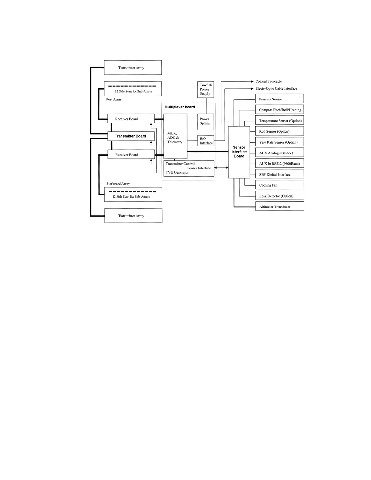
5-2 CHAPTER 5 Technical Description
Figure 5-1: Towfish Block Diagram—12 Sidescan Channels and 3 Bathymetery
Channels
Transmitter board. The Transmitter board produces a transmit pulse, at the
start of a swath, that ensonifies the sea floor over a defined footprint. The
Transmitter board is composed of two individual transmitting channels, one
connected to the port array and the other connected to the starboard array. The
transmitters operate at a center frequency of 455 kHz and support both CW and
chirp waveform transmission. The Transmitter board also contains transmit
and receive circuitry for the optional altimeter.
Receiver boards. The Receiver boards process the backscatter information
by applying fixed gain, time varied gain (TVG) and frequency filtering to the
input voltage signals received from the individual sub-arrays in the transducer
arrays. There are two Receiver boards, one for the port array and one for the
starboard array.
Each of the receiver channels is bandpass filtered with tightly matched filters
providing a -3dB bandwidth of 20 kHz, centered at 455 kHz. The filtered
signal is then output to the Multiplexer board for subsequent sampling.
Sensor Interface board. The Sensor Interface board conditions sensor data
from the compass board, depth pressure sensor, altimeter, and optional devices
for subsequent multiplexing and transmission to the TPU.
Series 5000 V2 Sonar System Operations and Maintenance Manual P/N 11214512, Rev. 04

Power Supply
board
Sensor Interface
board
Receiver
board (2)
Transmitter
board
Multiplexer
board
Compass
board
Figure 5-2: The Series 5000 V2 Sonar System TPU Electronics Chassis
Towfish 5-3

5-4 CHAPTER 5 Technical Description
Multiplexer board. The Multiplexer board digitizes the signals from each of
the transducer sub-array channels along with the signals from the sensors,
encodes the data, and transmits a high baud rate digital data stream to the TPU
by way of the tow cable. The Multiplexer board also receives the trigger signal
and command messages which instruct the T rans mitte r board to fire the arrays
and configure aspects of towfish operation. The Multiplexer board also acts as
a motherboard for the other boards providing the connections and distributing
power.
In addition, the Multiplexer board performs the following functions:
• Receives the 200 VDC and telemetry from the TPU and separates out the
telemetry from the 200 VDC.
• Routes the 200 VDC to the power supply, and then receives the converted
±12 VDC.
• Routes the 200 VDC to the Transmitter boards.
• Generates ±5 VDC, +3.3 VDC, and +28 VDC.
• Generates the time varied gain (TVG) curves for the received sonar signals
from the transducers.
• Multiplexes all the data channels and transmits the telemetry to the TPU.
• Provides cable uplink and downlink interface.
A full duplex hybrid allows data transmission up the cable while
simultaneously receiving the FSK trigger signals and power. The downlink
signals are input to FSK demodulators, and the baseband outputs are routed to
the Transmitter board, indicating when to fire the main array, and to a micro
controller that handles towfish configuration.
Compass board. The compass board provides heading, pitch and roll.
5.1.2 Transducer Arrays
The two transducer arrays are each composed of 12 piezoelectric ceramic
sub-arrays that operate as both transmit and receive elements. Each set of
12 sub-arrays is arranged into a continuous line array spanning an overall aperture
of 1.2 meters. When the bathymetry option is present, 3 additional receive arrays
are included that feed the additional channels of the receiver boards.
Series 5000 V2 Sonar System Operations and Maintenance Manual P/N 11214512, Rev. 04

5.2 TPU
A block diagram depicting the functional relationships of all of the printed circuit
boards in the TPU electronics is shown in Figure 5-3. These boards are located in
the TPU electronics chassis as shown in Figure 5-4. The printed circuit boards,
along with their corresponding part numbers, are the following:
Assembled into a single rack mountable 3U enclosure, the TPU connects to the
towfish directly or by way of an optionally supplied winch. It also connects to the
SonarPro Workstation over an Ethernet connection and to customer supplied
equipment, such as a GPS and an acoustic positioning system.
TPU 5-5
• Demultiplexer board 14105785
• CPU board 14105873
• High Voltage Power Supply board 11700098
• 200V Power Filter board 14104980
• Topside Telemetry board 14105841
• 12V Power Filter board 14105397
• 12V Power Supply board 11700092
• LED board 14105464
Demultiplexer board. The Demultiplexer board demultiplexes the uplink
sonar and sensor data from the towfish and outputs FSK downlink commands
along with 200 VDC power to the towfish while providing all of the external
input and output signal and data connections for the TPU. It also provides the
required recovery of signal and clock, detects trigger inputs and 1-PPS signals,
generates the trigger outputs, inputs NMEA 0183 data, time stamps all of the
data, and outputs the data to the SonarPro Workstation over the Ethernet
connection. 200 VDC power is input to the Demultiplexer board from the
200V Power Filter board, and 12 VDC power is input from the 12V Power
Filter board. The Demultiplexer board also provides front panel indicator
outputs which drive the front panel LEDs on the LED board.
CPU board. The CPU board functions as the command and data interface
between the SonarPro Workstation and the tow fish. It executes a real-time
data server which outputs sonar and sensor data to and receives commands
from an external client, such as SonarPro.
High Voltage Power Supply board. The High Voltage Power Supply board
provides 200 VDC which is output to the towfish to power it.
200V Power Filter board. The 200V Power Filter board provides noise
filtering of the 200 VDC power for transmission to the towfish over the coaxial
tow cable. The filtered 200 VDC power is output to the Demultiplexer board
where it is combined with the FSK control signals and output to the towfish.

Series 5000 V2 Sonar System Operations and Maintenance Manual P/N 11214512, Rev. 04
5-6 CHAPTER 5 Technical Description
Figure 5-3: The Series 5000 V2 Sonar System TPU Electronics Block Diagram

Topside Telemetry
board
CPU board
Demultiplexer
High Voltage
Power Supply
200V Power
Filter board
12V Power
Filter board
12V Power
Supply board
LED board
board
board
Figure 5-4: The Series 5000 V2 Sonar System TPU Electronics Chassis
TPU 5-7

5-8 CHAPTER 5 Technical Description
Topside Telemetry board. The Topside Telemetry board provides the cable
interface for the TPU. Specifically, the Topside Telemetry board performs the
following functions:
• Separates the uplink data signals, the downlink command signals and the
towfish power.
• Acquires sonar and sensor data and reformats the data as required for the
Demultiplexer board.
• Generates command and timing signals for the towfish.
• Matches the time references at the tow fish and the TPU.
12V Power Filter board. The 12V Power Filter board provides noise filtering
of the 12V power supply for the Demultiplexer board.
12V Power Supply board. The 12V Power Supply board inputs 100–125 or
200–250 VAC and outputs 12 VDC to the 12V Power Filter board.
LED board. The LED board contains all of the front panel LED indicators. It
mounts directly to the back of the front panel and connects to the
Demultiplexer board over a single cable.
Series 5000 V2 Sonar System Operations and Maintenance Manual P/N 11214512, Rev. 04

APPENDIX A: SAMPLE TOWING
CHARACTERISTICS
Five towing characteristic graphs are included in this appendix as Figure A-1
through Figure A-5. Two of the graphs were generated without any additional
weight being added to the towfish, and the other two graphs were made with our
K-Wing II Depressor attached to the towfish. We believe you will find these
graphs helpful in planning your surveys and equipment requirements.
As with any projections of this type, certain conditions and assumptions were
made in order to generate a reasonable quantity of data with some degree of
accuracy. Read all the conditions below before you attempt to use the data.
Data. Data were computer generated using programs of known prediction
accuracy in both military and commercial towing systems. At best this type of
data provides "ballpark" values versus absolute values. These curves have been
checked with field data wherever possible. At best the values are within 15%
accurate with the greatest accuracy at towfish depths between 91 m (300 ft)
and 914 m (3000 ft) and at tow speeds of 3 to 7 knots. They are least accurate
at slow speeds and short cable lengths.
A-1
NOTE Depressors have minimal effect at speeds of 2 knots or less. Boat
motion plays a large role in shallow towing. For very deep towing, ocean
currents can completely change the cable characteristics.
Tow Cables. T ow cables having the characteristics below were used. Should
you have a different cable, it could make a significant difference.
• 10.2 mm (0.40 in.) nominal diameter double armored, galvanized steel;
weighing 353 kg per 1000 m (237 lb per 1000 ft) in air; 353 kN (11,000 lb)
breaking strength.
• 17.3 mm (0.68 in.) nominal diameter double armored, galvanized steel;
weighing 1030 kg per 1000 m (692 lb per 1000 ft) in air; 178 kN
(40,000 lb) breaking strength.
Cable drag increases with increasing cable diameter. The drag increases as the
velocity squared (V2). As cable weight per unit length increases, the cable tows
deeper.

A-2 APPENDIX A Sample Towing Characteristics
Towfish. The Klein Model 5250 stainless steel towfish was used in all cases.
It weighs 48 kg (105 lb) in water, is 16.8 cm (6.6 in.) in diameter and has a
length of 203 cm (79.9 in.). Smaller or larger towfish will only make a
difference when being towed on a cable of less than 60 m (200 ft) length at
speeds slower than 2 knots.
Depressor. The Klein K-Wing II, Model 402A-002 was used to create the
depressive forces in the calculations shown on three of the graphs. The K-W ing
mounts directly to the towfish end.
Interpreting the Graphs. Pick the graph closest to your operating
conditions. With a given speed and cable length, you can determine effective
tow depth. You can also determine the cable length required to reach a specific
depth at a given speed.
NOTE The graphs were calculated with the equipment and conditions
noted. The data can be used for different equipment and conditions by
extrapolating the data from the graphs.
More details on towing characteristics, such as tension, layback, etc., are available
at Klein Marine Systems, Inc. We would be glad to help you meet your
requirements. Your experiences in towing our side scan sonar under various
conditions would be helpful in upgrading our data, and we respectfully solicit your
comments.
Series 5000 V2 Sonar System Operations and Maintenance Manual P/N 11214512, Rev. 04

Figure A-1: Cable Length vs. Towfish Depth Graph 1
A-3

Series 5000 V2 Sonar System Operations and Maintenance Manual P/N 11214512, Rev. 04
A-4 APPENDIX A Sample Towing Characteristics
Figure A-2: Cable Length vs. Towfish Depth Graph 2

Figure A-3: Cable Length vs. Towfish Depth Graph 3
A-5

Series 5000 V2 Sonar System Operations and Maintenance Manual P/N 11214512, Rev. 04
A-6 APPENDIX A Sample Towing Characteristics
Figure A-4: Cable Length vs. Towfish Depth Graph 4

Figure A-5: Cable Length vs. Towfish Depth Graph 5
A-7


APPENDIX B: NOTES ON HANDLING TOW
CABLES
A few methods on how to safely unreel tow cables are provided in this appendix.
In addition, how cable kinking can occur is identified along with what can result
from this condition.
B.1 Unreeling Tow Cable
The reel should be revolved and the rope taken off the way it was put on the reel as
shown in Figure B-1 for two effective methods. Place a shaft through the reel
center and jack it up so that the reel revolves freely. Pull the cable straight ahead,
keeping it taut, to prevent the cable from becoming loose on the reel. A board held
against a flange may be used as a brake to prevent the reel from revolving too fast.
B-1
Figure B-1: Correct Methods to Unreel Tow Cable

B-2 APPENDIX B Notes on Handling Tow Cables
B.2 Uncoiling Tow Cable
Remove ties and roll the coil along the ground so the rope lies straight. There will
be no twist or kink in the cable if these instructions are followed.
CAUTION If the reel and coil do not revolve freely, it will cause the cable
to twist as each turn is taken off. Kinking will result if the twist is not
removed and the cable straightened out before being placed under tension.
B.3 Cable Kinking
Cable kinking can be prevented if the cable is properly handled and installed. The
cause, the effect and the result of cable kinking are discussed below.
B.3.1 Cause of Cable Kinking
Kinking is caused when the cable takes a spiral shape as the result of an unnatural
twist. One of the most common causes of twisting is improper unreeling and
uncoiling. A cable loop and a cable kink are shown in Figure B-3. At the loop
stage no damage will occur if the loop is immediately straightened out before it
causes a kink.
Figure B-2: Spooling Real to Drum
Series 5000 V2 Sonar System Operations and Maintenance Manual P/N 11214512, Rev. 04

Cable Kinking B-3
Cable Loop Cable Kink
Figure B-3: Cable Loop and Kink
B.3.2 Effect of Cable Kinking
The effect of kinking is shown in Figure B-4. The cable is permanently damaged
Figure B-4: Damaged Cable
B.3.3 Result of Cable Kinking
The result of cable kinking is that strands and wires are displaced, creating uneven
tension which causes excessive wear at the point of the kink. The kink can be
straightened out so that the damage appears slight; however, since the relative
adjustment between strands has been disturbed, the cable cannot give maximum
service.


C-1
APPENDIX C: CONFIGURING AND UPDATING
THE TPU
The TPU is configured at the factory. However, should changes be required,
configuring and updating the TPU can be performed using Linux Updater. This
program is automatically installed when installing SonarPro and can be used to
perform the following tasks:
• Query or change the IP address of the TPU.
• Edit the startup file of the TPU.
• Download and install software updates to the TPU.
C.1 Starting Linux TPU Updater
Linux TPU Updater is started by double-clicking the Linux TPU Updater
icon on the Windows desktop. The Klein Linux TPU Updater dialog box will
open as shown Figure C-1.
Figure C-1: The Klein Linux TPU Updater Dialog Box

C-2 APPENDIX C Configuring and Updating the TPU
C.2 Querying or Changing the TPU IP Address
The TPU IP address is set up at the factory. The factory set default IP address is
192.168.0.81. However, should a different address be required, it can be changed.
To change the TPU IP address:
1. Connect the supplied null modem cable to the NAV connector of the
TPU and to an available serial port on the SonarPro Workstation.
2. Turn on the SonarPro Workstation and wait for the Windows desktop to appear.
3. Turn on the TPU.
4. Start Linux TPU Updater.
The Klein Linux TPU Updater dialog box opens.
5. Click Read TPU IP Address.
The Select RS-232 Port dialog box shown in Figure C-2 opens.
Figure C-2: The Select RS-232 Port Dialog Box.
6. From the Port drop-down list box, select the serial port on the SonarPro
Workstation to which the TPU is connected.
7. From the Rate drop-down list box, select the baud rate of the TPU’s NAV serial
port, or select Determine Automatically to have Linux TPU Updater find the rate.
The Klein Linux TPU Updater dialog box opens with the current IP address
displayed in the
Series 5000 V2 Sonar System Operations and Maintenance Manual P/N 11214512, Rev. 04
TPU IP Address text box as shown in Figure C-3.

Editing the TPU Startup File C-3
Figure C-3: The Klein Linux TPU Updater Dialog Box with Current TPU IP
Address Displayed
8. Enter the new address in the Enter New IP Address text box, and then click Set
TPU IP Address
.
A window opens confirming the change:
C.3 Editing the TPU Startup File
The startup file for the TPU is startupCdi3000.ini.
To edit the TPU startup file:
1. Connect the supplied Ethernet cable to the LAN connector of the TPU and to
the ETHERNET connector of the SonarPro Workstation.
2. Turn on the SonarPro Workstation and wait for the Windows desktop to appear.
3. Turn on the TPU.
4. Start Linux TPU Updater.
The Klein Linux TPU Updater dialog box opens.

C-4 APPENDIX C Configuring and Updating the TPU
5. Enter the TPU IP address in the Enter TPU IP Address text box if it is different
than the default address, or click
address is 192.168.0.81. The address will already be displayed if it was
queried or changed as described in “Querying or Changing the TPU IP Address”
on page C-2.
6. Click Edit startup.ini.
Windows Notepad opens with the contents of the startupCdi3000.ini file
displayed.
7. Make the required changes to the startupCdi3000.ini file as required, and then
exit Notepad.
Notepad exits and the changed file is saved. The TPU software restarts and a
window opens confirming the file update:
Default Addr if it is the default. The default
8. To ensure a clean start with the new update, in about 20 seconds, turn the
TPU off and then on again.
C.4 Updating the TPU Software
Updates to the TPU software are supplied as compressed archive files and must
reside on the SonarPro Workstation or the laptop computer.
To update the TPU software:
1. Connect the supplied Ethernet cable to the LAN connector of the TPU and to
the ETHERNET connector of the SonarPro Workstation.
2. Turn on the SonarPro Workstation and wait for the Windows desktop to appear.
3. Turn on the TPU.
4. Start Linux TPU Updater.
The Klein Linux TPU Updater dialog box opens.
Series 5000 V2 Sonar System Operations and Maintenance Manual P/N 11214512, Rev. 04

Updating the TPU Software C-5
5. Enter the TPU IP address in the Enter TPU IP Address text box if it is different
than the default address, or click
address is 192.168.0.81. The address will already be displayed if it was
queried or changed as described in “Querying or Changing the TPU IP Address”
on page C-2.
6. Click Update TPU Software.
Default Addr if it is the default. The default
An dialog box opens that enables file selection.
7. Select and open the update file to download and install.
The file is downloaded to the TPU and installed, and the TPU software
restarts. In about two minutes, a window opens confirming the software
update:


APPENDIX D: DIFFERENT TOW CABLE
LENGTHS AND THE
STARTUP.INI FILE
The Series 5000 V2 Sonar System operates at high data rates. For optimum
performance, settings have been provided to tune the system’s uplink for various
cable lengths up to -24 dB of insertion loss. The adjustment settings are made in
the Startup.ini file using the following two lines:
set PREEMPHISIS x
set LBOGAIN x
This file may be opened in any text editor such as Wordpad. After editing, save the
file.
D-1
The adjustment parameters are as follows:
set PREEMPHISIS x x = (0-7) SonarPro Command $ML x
set LBOGAIN x x = (0-3) SonarPro Command $MG x
We recommend the following:
For a 15-meter cable,
set PREEMPHISIS 1
set LBOGAIN 0
For a 150-meter cable,
set PREEMPHISIS 3
set LBOGAIN 1
For cables around 600 meters,
set PREEMPHISIS 7
set LBOGAIN 2
For cables that are longer, experimentation with the above settings should be done.
To do this, watch the yellow ERROR indicator on the TPU front panel. Vary the
uplink parameters until error-free operation is achieved. We recommend running
SonarPro and using the Towfish Diagnostics tab of the Sonar Interface dialog box.
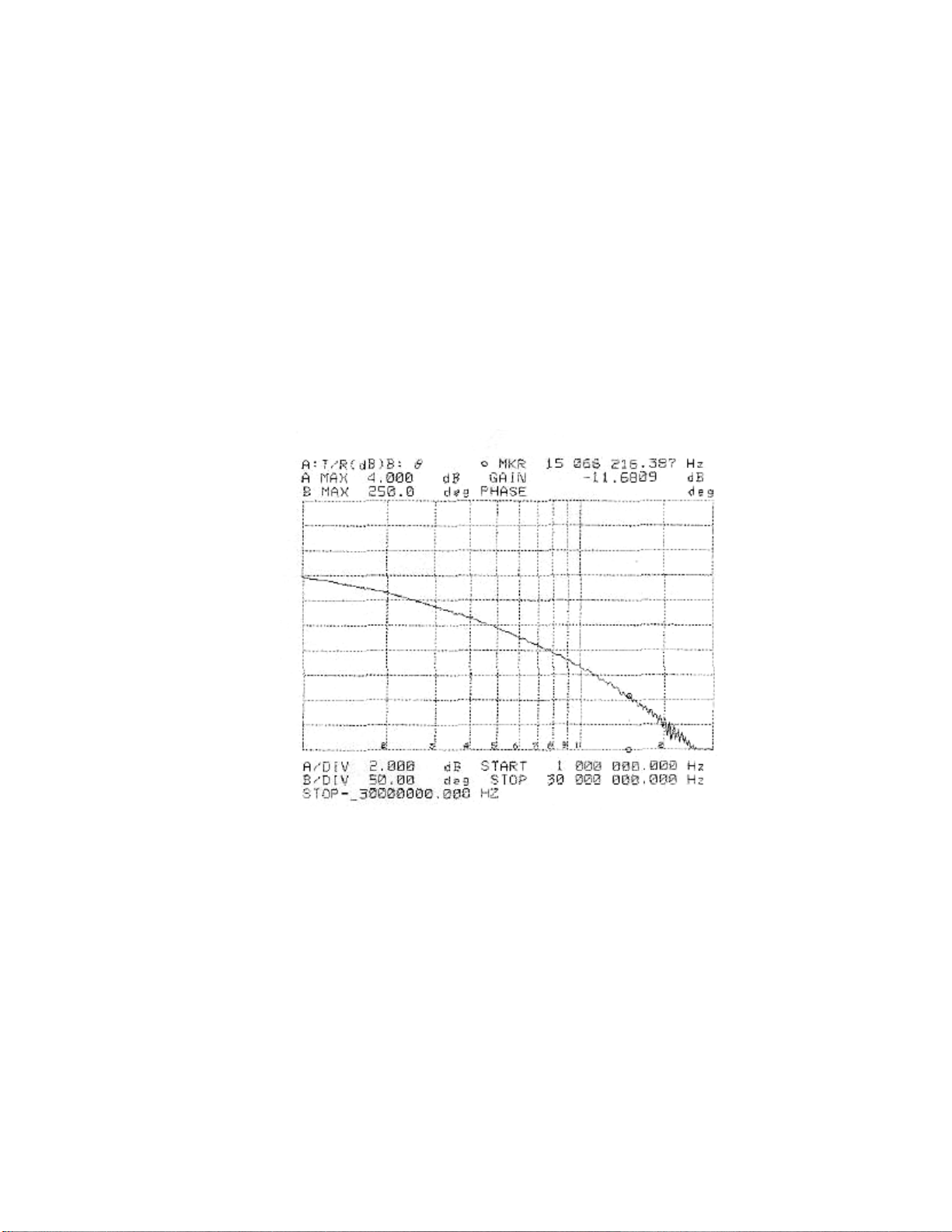
D-2 APPENDIX D Different Tow Cable Lengths and the Startup.ini File
For example, when testing a 1000-meter cable, from SonarPro the following
command set yielded error-free operation: $MG2 and $ML7. Therefore the
Startup.ini file would be adjusted to contain the following:
set PREEMPHISIS 7
set LBOGAIN 2
D.1 Measuring Cable Insertion Loss
T o get an accurate assessme nt of your tow cable assembly, we suggest that you use
a Hewlett Packard 4194A Impedance/Gain-Phase Analyzer or similar.
A sample plot is shown in Figure D-1.
Figure D-1: Sample Plot of Tow Cable Characteristics
If you do not have access to a Hewlett Packard 4194A Impedance/Gain-Phase
Analyzer, you can get a close reading by using a function generator, a 50-ohm
terminator and an oscilloscope as shown in Figure D-2.
With the function generator and the oscilloscope connected to the cable, monitor
input on the oscilloscope and input a 1 volt peak (2 volt peak-to-peak) sine wave of
the specific frequency of interest. Measure the peak output at the other end of the
cable on the scope through the 50-ohm termination.
Series 5000 V2 Sonar System Operations and Maintenance Manual P/N 11214512, Rev. 04

Figure D-2: Setup for Measuring Tow Cable Characteristics using a
50 ohm terminator
Scope
Cable
Assembly
Function
Generator
Use the formula
Spare Tow Cable D-3
Function Generator, Terminator and Oscilloscope
dB = 20 log (Vout /Vin)
For example, if at 15 MHz, you get a reading of 160 mv, then
dB = 20 log (0.16/1.0) = 15.9 dB loss.
NOTE The whole cable assembly must not exceed an attenuation of gr eater
than 24 dB of insertion loss at 15 MHz. We suggest a working loss of 24 dB
at 15 MHz.
D.2 Spare Tow Cable
Given the nature of high speed towing, cable problems can occur. For
troubleshooting purposes we suggest that you have on hand a lightweight Kevlar
reinforced 150-meter (minimum length) tow cable. This extra cable will allow you
to bypass your primary tow cable assembly and speed up fault isolation.


E-1
APPENDIX E: DRAWINGS AND PARTS LISTS
Listed in T able E-1 are the drawings and parts lists included in this appendix. They
are provided for reference and troubleshooting purposes. Each assembly drawing
is followed by its corresponding parts list.
Table E-1: List of Drawings and Parts Lists
DRAWING
NO.
14315912
14600134
14314554
15104554
15100952
14315006
15105006
15104917
15100963
PARTS
LIST NO.
14104554
14105284
14105006
14104917
TITLE
Wiring Diagram, TP 5000 Rackmount
Outline Drawing, Towfish
Wiring Diagram, Chassis Electronics, Towfish, Series 5000 V2
Assembly Drawing, Electronics Bottle, T owfish, 5000 V2, Sheets
1 and 2
Assembly, Electronics Bottle, Towfish, 5000 V2
Assembly Drawing, Option Kit .25” Tailfin, “T” Sys 5000
Assembly, Spares Kit, Tailfins/Cone, 5000-V2
Wiring Diagram, Chassis Electronics, Towfish, Series 5000 V2
Bathy
Assembly Drawing, Electronics Bottle, Towfish 5000 V2 Bathy,
Sheets 1 and 2
Assembly , Electronics Bottle, Towfish 5000 V2 Bathy
Assembly Drawing, Nosecone DMB, Black
Assembly, Nosecone DMB
Assembly Drawing, Cable Term, BHD Conn, Armored Coax
15101000
14102919100M
14102967100M
14103017
Assembly, Cable Term, BHD Conn, Armored Coax, .40
Assembly, Cable Term, BHD Conn, Armored Coax, .525
Assembly Drawing, Cable Term, BHD Conn, Armored Coax,
0.68"
Assembly, Cable Term, BHD Conn, Armored Coax, 0.68"

Series 5000 V2 Sonar System Operations and Maintenance Manual P/N 11214512, Rev. 04
E-2 APPENDIX E Drawings and Parts Lists

E-3

Series 5000 V2 Sonar System Operations and Maintenance Manual P/N 11214512, Rev. 04
E-4 APPENDIX E Drawings and Parts Lists

E-5

Series 5000 V2 Sonar System Operations and Maintenance Manual P/N 11214512, Rev. 04
E-6 APPENDIX E Drawings and Parts Lists

E-7

Series 5000 V2 Sonar System Operations and Maintenance Manual P/N 11214512, Rev. 04
E-8 APPENDIX E Drawings and Parts Lists
 Loading...