

Klein 5000 SERIES Operation And Maintenance Manual
SERIES 5000 SONAR
SYSTEM
Operations and Maintenance Manual
P/N 11210060, Rev. 16
11 Klein Drive
Salem, NH 03079-1249
U.S.A.
Tel: (603) 893-6131
Fax: (603) 893-8807
www.KleinMarineSystems.com

ii
This document contains proprietary information, and such information may not be
disclosed to others for any purpose or used for any manufacturing purpose without
expressed written permission from Klein Marine Systems, Inc. (KMS). The
information provided is for informational purposes only and is subject to change
without notice. KMS assumes no responsibility or liability for any errors,
inaccuracies or omissions that may be present in this document.
The SonarPro software program may be used or copied only in accordance with
the terms of the Software License Agreement.
©
Copyright 2007–2016 by Klein Marine Systems, Inc. All rights reserved.
SonarPro® is a registered trademark of Klein Marine Systems, Inc.
K-Wing® and K-Wing II® are a registered trademarks of Klein Marine Systems,
Inc.
Intel® and Pentium®are registered trademarks of Intel Corporation.
Windows® is a registered trademark of Microsoft Corporation.
vxWorks® is a registered trademark of Wind River Systems, Inc.
Kevlar® is a registered trademark of the DuPont Company.
Series 5000 Sonar System Operations and Maintenance Manual P/N 11210060, Rev. 16

WARNING
Klein Marine Systems recommends all troubleshooting be done by
a trained technician. Some circuits in the Sonar Transceiver and
Processing Unit have voltages as high as 240 volts, and some
circuits in the sonar towfish have 1500 volts. You should
familiarize yourself with the location of these voltages before you
attempt any troubleshooting. Failure to observe these warnings
could result in injuries to personnel.
CAUTION
Serious damage to the sonar electronics may occur if the sonar
towfish is operated out of the water for periods longer than 15
minutes. Let the sonar cool 15 minutes or longer between
operations. Protect the sonar towfish from direct exposure to the
sun prior to and during operation in high temperature climates.
iii
CAUTION
The depth rating on the transducers is 200 meters (656 feet).
Operations at depths greater than 200 meters may damage the
transducers.
STANDARDS
SAFETY: EN 60950
EMC: EN 60945

iv
Table of Contents
Table of Contents . . . . . . . . . . . . . . . . . . . . . . . . . . . . . . . . . . . . . . . . . . . . iv
List of Figures . . . . . . . . . . . . . . . . . . . . . . . . . . . . . . . . . . . . . . . . . . . . . . . . x
List of Tables . . . . . . . . . . . . . . . . . . . . . . . . . . . . . . . . . . . . . . . . . . . . . . xiii
Sonar System Warranty . . . . . . . . . . . . . . . . . . . . . . . . . . . . . . . . . . . . . . xiv
What Is Covered . . . . . . . . . . . . . . . . . . . . . . . . . . . . . . . . . . . . . . . . . . xiv
Conditions Of Warranty . . . . . . . . . . . . . . . . . . . . . . . . . . . . . . . . . . . . . xv
Changes, Errors And Ommissions . . . . . . . . . . . . . . . . . . . . . . . . . . . . xvi
Software License Agreement . . . . . . . . . . . . . . . . . . . . . . . . . . . . . . . . . xvii
Preface . . . . . . . . . . . . . . . . . . . . . . . . . . . . . . . . . . . . . . . . . . . . . . . . . . . xix
What’s in This Manual . . . . . . . . . . . . . . . . . . . . . . . . . . . . . . . . . . . . . xix
Note, Warning, Caution, and Shock Hazard Notices . . . . . . . . . . . . . . . xx
Customer Service . . . . . . . . . . . . . . . . . . . . . . . . . . . . . . . . . . . . . . . . . . . . xx
CHAPTER 1: Overview . . . . . . . . . . . . . . . . . . . . . . . . . . . . . . . . . . . 1-1
1.1 Equipment . . . . . . . . . . . . . . . . . . . . . . . . . . . . . . . . . . . . . . . . . 1-1
1.1.1 Multibeam Sonar Instrumented Towfish . . . . . . . . . . . . . . . . 1-1
1.1.2 Transceiver and Processing Unit (TPU) . . . . . . . . . . . . . . . . . 1-1
1.1.3 Computer Display and Control Unit . . . . . . . . . . . . . . . . . . . . 1-2
1.1.4 Tow Cable . . . . . . . . . . . . . . . . . . . . . . . . . . . . . . . . . . . . . . . 1-2
1.2 Features . . . . . . . . . . . . . . . . . . . . . . . . . . . . . . . . . . . . . . . . . . . 1-2
1.3 Physical Description . . . . . . . . . . . . . . . . . . . . . . . . . . . . . . . . . 1-2
1.3.1 Surface Equipment . . . . . . . . . . . . . . . . . . . . . . . . . . . . . . . . . 1-2
1.3.2 Subsurface Equipment . . . . . . . . . . . . . . . . . . . . . . . . . . . . . . 1-3
1.4 Theory of Operation . . . . . . . . . . . . . . . . . . . . . . . . . . . . . . . . . . 1-4
1.4.1 Introduction . . . . . . . . . . . . . . . . . . . . . . . . . . . . . . . . . . . . . . 1-4
1.4.2 Towfish . . . . . . . . . . . . . . . . . . . . . . . . . . . . . . . . . . . . . . . . . . 1-5
1.4.3 Transceiver and Processing Unit . . . . . . . . . . . . . . . . . . . . . . 1-8
Series 5000 Sonar System Operations and Maintenance Manual P/N 11210060, Rev. 16

CHAPTER 2: Specifications . . . . . . . . . . . . . . . . . . . . . . . . . . . . . . . 2-1
2.1 Sonar System . . . . . . . . . . . . . . . . . . . . . . . . . . . . . . . . . . . . . . . 2-1
2.2 Sonar Transceiver and Processing Unit (TPU) . . . . . . . . . . . . . 2-2
2.2.1 TPU Operation . . . . . . . . . . . . . . . . . . . . . . . . . . . . . . . . . . . . 2-2
2.2.2 Input/Output Ports (I/O) . . . . . . . . . . . . . . . . . . . . . . . . . . . . . 2-2
2.2.3 Trigger Input . . . . . . . . . . . . . . . . . . . . . . . . . . . . . . . . . . . . . . 2-2
2.2.4 Trigger Outputs . . . . . . . . . . . . . . . . . . . . . . . . . . . . . . . . . . . 2-2
2.2.5 RS-232 COM 1 Port . . . . . . . . . . . . . . . . . . . . . . . . . . . . . . . . 2-2
2.2.6 RS-232 COM 2 Port . . . . . . . . . . . . . . . . . . . . . . . . . . . . . . . . 2-3
2.2.7 LAN Input/Output Port . . . . . . . . . . . . . . . . . . . . . . . . . . . . . 2-3
2.2.8 Power Input . . . . . . . . . . . . . . . . . . . . . . . . . . . . . . . . . . . . . . 2-3
2.2.9 Physical Characteristics . . . . . . . . . . . . . . . . . . . . . . . . . . . . . 2-3
2.3 Computer Display and Control Unit . . . . . . . . . . . . . . . . . . . . . 2-3
v
2.4 Ethernet Hub . . . . . . . . . . . . . . . . . . . . . . . . . . . . . . . . . . . . . . . 2-3
2.5 Towfish . . . . . . . . . . . . . . . . . . . . . . . . . . . . . . . . . . . . . . . . . . . 2-3
2.5.1 General . . . . . . . . . . . . . . . . . . . . . . . . . . . . . . . . . . . . . . . . . . 2-3
2.5.2 Transducers . . . . . . . . . . . . . . . . . . . . . . . . . . . . . . . . . . . . . . . 2-3
2.5.3 Transmitter . . . . . . . . . . . . . . . . . . . . . . . . . . . . . . . . . . . . . . . 2-4
2.5.4 Receiver . . . . . . . . . . . . . . . . . . . . . . . . . . . . . . . . . . . . . . . . . 2-4
2.5.5 A/D Converter . . . . . . . . . . . . . . . . . . . . . . . . . . . . . . . . . . . . 2-4
2.5.6 Multiplexer . . . . . . . . . . . . . . . . . . . . . . . . . . . . . . . . . . . . . . . 2-4
2.5.7 Power . . . . . . . . . . . . . . . . . . . . . . . . . . . . . . . . . . . . . . . . . . . 2-4
2.5.8 Physical Characteristics . . . . . . . . . . . . . . . . . . . . . . . . . . . . . 2-4
2.5.9 Heading Sensor . . . . . . . . . . . . . . . . . . . . . . . . . . . . . . . . . . . . 2-5
2.5.10 Pitch and Roll Sensor . . . . . . . . . . . . . . . . . . . . . . . . . . . . . . . 2-5
2.5.11 Pressure Sensor . . . . . . . . . . . . . . . . . . . . . . . . . . . . . . . . . . . . 2-5
2.6 Tow Cables . . . . . . . . . . . . . . . . . . . . . . . . . . . . . . . . . . . . . . . . 2-5
2.6.1 Lightweight Tow Cable . . . . . . . . . . . . . . . . . . . . . . . . . . . . . 2-5
2.6.2 Steel Tow Cable . . . . . . . . . . . . . . . . . . . . . . . . . . . . . . . . . . . 2-6
2.7 Options . . . . . . . . . . . . . . . . . . . . . . . . . . . . . . . . . . . . . . . . . . . . 2-6
2.7.1 Towfish Options . . . . . . . . . . . . . . . . . . . . . . . . . . . . . . . . . . . 2-6
2.7.2 Tow Cable Options . . . . . . . . . . . . . . . . . . . . . . . . . . . . . . . . . 2-6

vi
CHAPTER 3: Preparation for Use . . . . . . . . . . . . . . . . . . . . . . . . . . 3-1
3.1 Unpacking and Inspection . . . . . . . . . . . . . . . . . . . . . . . . . . . . . 3-1
3.1.1 Unpacking the TPU . . . . . . . . . . . . . . . . . . . . . . . . . . . . . . . . 3-1
3.1.2 Unpacking the Computer Display and Control
Unit (Computer) . . . . . . . . . . . . . . . . . . . . . . . . . . . . . . . . . . . 3-1
3.1.3 Unpacking the Towfish . . . . . . . . . . . . . . . . . . . . . . . . . . . . . 3-2
3.1.4 Unpacking the Tow Cable . . . . . . . . . . . . . . . . . . . . . . . . . . . 3-2
3.2 Mechanical Installation of the TPU and Computer . . . . . . . . . . 3-2
3.2.1 Location . . . . . . . . . . . . . . . . . . . . . . . . . . . . . . . . . . . . . . . . . 3-2
3.2.2 Mounting . . . . . . . . . . . . . . . . . . . . . . . . . . . . . . . . . . . . . . . . 3-2
3.2.3 Isolating from Shock and Vibration . . . . . . . . . . . . . . . . . . . . 3-2
3.3 Power Connection . . . . . . . . . . . . . . . . . . . . . . . . . . . . . . . . . . . 3-3
3.3.1 Connecting Cables and Power Cords . . . . . . . . . . . . . . . . . . . 3-3
3.3.2 Power Line Fuse . . . . . . . . . . . . . . . . . . . . . . . . . . . . . . . . . . . 3-4
3.3.3 Towfish Fuse . . . . . . . . . . . . . . . . . . . . . . . . . . . . . . . . . . . . . 3-4
3.3.4 Grounding . . . . . . . . . . . . . . . . . . . . . . . . . . . . . . . . . . . . . . . . 3-5
3.4 Towfish Setup . . . . . . . . . . . . . . . . . . . . . . . . . . . . . . . . . . . . . . 3-5
3.4.1 General Rigging Notes and Cautions . . . . . . . . . . . . . . . . . . . 3-5
3.4.2 Tow Cable Electrical Connection . . . . . . . . . . . . . . . . . . . . . . 3-6
3.4.3 Towfish and Optional Depressor Connection . . . . . . . . . . . . 3-7
3.4.4 Tow Cable Disconnection . . . . . . . . . . . . . . . . . . . . . . . . . . . 3-8
3.5 Quick Start Installation and Operating Guide . . . . . . . . . . . . . . 3-9
3.5.1 Hardware Installation . . . . . . . . . . . . . . . . . . . . . . . . . . . . . . . 3-9
3.5.2 Deck Test . . . . . . . . . . . . . . . . . . . . . . . . . . . . . . . . . . . . . . . 3-10
3.5.3 At-Sea Test . . . . . . . . . . . . . . . . . . . . . . . . . . . . . . . . . . . . . . 3-11
CHAPTER 4: Equipment Maintenance . . . . . . . . . . . . . . . . . . . . . . 4-1
4.1 Maintenance General Comments . . . . . . . . . . . . . . . . . . . . . . . . 4-1
4.2 Maintenance Checklists . . . . . . . . . . . . . . . . . . . . . . . . . . . . . . . 4-1
4.2.1 Daily Maintenance Checklist . . . . . . . . . . . . . . . . . . . . . . . . . 4-1
4.2.2 Weekly Maintenance Checklist . . . . . . . . . . . . . . . . . . . . . . . 4-2
4.2.3 Long Term Maintenance Checklist . . . . . . . . . . . . . . . . . . . . 4-2
4.3 Replacing the Fixed Tail Cone Assembly . . . . . . . . . . . . . . . . . 4-3
4.4 Removing the Fixed Tail Cone Assembly . . . . . . . . . . . . . . . . . 4-6
Series 5000 Sonar System Operations and Maintenance Manual P/N 11210060, Rev. 16

vii
CHAPTER 5: Splashproof TPU . . . . . . . . . . . . . . . . . . . . . . . . . . . . . 5-1
5.1 General Description . . . . . . . . . . . . . . . . . . . . . . . . . . . . . . . . . . 5-1
5.1.1 Venting the Splashproof TPU . . . . . . . . . . . . . . . . . . . . . . . . 5-2
5.1.2 External Connections . . . . . . . . . . . . . . . . . . . . . . . . . . . . . . . 5-2
5.1.3 Operator Controls and Indicators . . . . . . . . . . . . . . . . . . . . . . 5-4
5.1.4 Functional Components . . . . . . . . . . . . . . . . . . . . . . . . . . . . . 5-7
5.2 Setting up and Connecting the Splashproof TPU . . . . . . . . . . . 5-9
5.2.1 Included Accessories . . . . . . . . . . . . . . . . . . . . . . . . . . . . . . . 5-9
5.2.2 Connecting Power . . . . . . . . . . . . . . . . . . . . . . . . . . . . . . . . . 5-9
5.3 Activating the Splashproof TPU . . . . . . . . . . . . . . . . . . . . . . . 5-10
5.4 Specifications . . . . . . . . . . . . . . . . . . . . . . . . . . . . . . . . . . . . . . 5-11
5.5 Splashproof TPU Drawings . . . . . . . . . . . . . . . . . . . . . . . . . . . 5-11
APPENDIX A: Sample Towing Characteristics . . . . . . . . . . . . . . . . A-1
APPENDIX B: Notes on Handling Tow Cables . . . . . . . . . . . . . . . . B-1
B.1 Unreeling Tow Cable . . . . . . . . . . . . . . . . . . . . . . . . . . . . . . . . . B-1
B.2 Uncoiling Tow Cable . . . . . . . . . . . . . . . . . . . . . . . . . . . . . . . . . B-2
B.3 Cable Kinking . . . . . . . . . . . . . . . . . . . . . . . . . . . . . . . . . . . . . . B-2
B.3.1 Cause of Cable Kinking . . . . . . . . . . . . . . . . . . . . . . . . . . . . . B-2
B.3.2 Effect of Cable Kinking . . . . . . . . . . . . . . . . . . . . . . . . . . . . . B-3
B.3.3 Result of Cable Kinking . . . . . . . . . . . . . . . . . . . . . . . . . . . . . B-3
APPENDIX C: TPU Software Interface and Control . . . . . . . . . . . . C-1
C.1 Control Methods . . . . . . . . . . . . . . . . . . . . . . . . . . . . . . . . . . . . C-1
C.2 Startup Script . . . . . . . . . . . . . . . . . . . . . . . . . . . . . . . . . . . . . . . C-1
C.3 Remote Control . . . . . . . . . . . . . . . . . . . . . . . . . . . . . . . . . . . . C-10
C.4 Snapshots . . . . . . . . . . . . . . . . . . . . . . . . . . . . . . . . . . . . . . . . . C-14
C.5 Messages . . . . . . . . . . . . . . . . . . . . . . . . . . . . . . . . . . . . . . . . . C-15
C.5.1 Status Message . . . . . . . . . . . . . . . . . . . . . . . . . . . . . . . . . . . C-15
C.5.2 Heartbeat Message . . . . . . . . . . . . . . . . . . . . . . . . . . . . . . . . C-16
C.5.3 Sensor Message . . . . . . . . . . . . . . . . . . . . . . . . . . . . . . . . . . C-16

viii
C.6 Towfish Commands . . . . . . . . . . . . . . . . . . . . . . . . . . . . . . . . . C-17
C.6.1 5000 System MUX Commands . . . . . . . . . . . . . . . . . . . . . . C-17
C.6.2 5000 System Transmitter Commands . . . . . . . . . . . . . . . . . C-18
C.6.3 System 5000 Actuator Commands . . . . . . . . . . . . . . . . . . . . C-19
C.6.4 3000 System Multiplexer Commands . . . . . . . . . . . . . . . . . C-19
C.6.5 Auxiliary and Compass Commands . . . . . . . . . . . . . . . . . . . C-19
C.6.6 System 5900 MUX Commands . . . . . . . . . . . . . . . . . . . . . . C-20
C.6.7 System 5900 DSP Commands . . . . . . . . . . . . . . . . . . . . . . . C-21
C.6.8 System 5900 Transmitter Commands . . . . . . . . . . . . . . . . . C-21
C.6.9 System x000 Sub-Bottom Profiler (SBP) Commands. . . . . C-22
C.6.10 Datalogger On/Off commands . . . . . . . . . . . . . . . . . . . . . . . C-23
APPENDIX D: General Setup, Configuration and
Troubleshooting . . . . . . . . . . . . . . . . . . . . . . . . . . . . . D-1
D.1 Basic System Requirements . . . . . . . . . . . . . . . . . . . . . . . . . . . D-2
D.2 Basic System Setup . . . . . . . . . . . . . . . . . . . . . . . . . . . . . . . . . D-2
D.3 Installing SonarPro . . . . . . . . . . . . . . . . . . . . . . . . . . . . . . . . . . D-5
D.4 Configuring the LAN Connection . . . . . . . . . . . . . . . . . . . . . . D-5
D.4.1 Windows NT LAN Configuration Setup . . . . . . . . . . . . . . . D-5
D.4.2 Windows 2000 LAN Configuration Setup . . . . . . . . . . . . . D-11
D.4.3 Windows XP LAN Configuration Setup . . . . . . . . . . . . . . D-16
D.5 T PU LAN Configuration Setup . . . . . . . . . . . . . . . . . . . . . . . D-24
D.6 D ifferent Cable Lengths and the Startup.ini File . . . . . . . . . . D-29
D.6.1 Tow Cable Considerations . . . . . . . . . . . . . . . . . . . . . . . . . D-30
D.6.2 Measuring Cable Insertion Loss . . . . . . . . . . . . . . . . . . . . . D-31
D.6.3 Spare Tow Cable . . . . . . . . . . . . . . . . . . . . . . . . . . . . . . . . D-32
D.7 Transceiver and Processing Unit . . . . . . . . . . . . . . . . . . . . . . D-32
D.7.1 Input Power . . . . . . . . . . . . . . . . . . . . . . . . . . . . . . . . . . . . D-33
D.7.2 Towfish Fuse . . . . . . . . . . . . . . . . . . . . . . . . . . . . . . . . . . . D-34
D.7.3 TPU Block Diagram . . . . . . . . . . . . . . . . . . . . . . . . . . . . . . D-34
D.7.4 TPU Internal Access . . . . . . . . . . . . . . . . . . . . . . . . . . . . . . D-34
D.7.5 Power Supplies . . . . . . . . . . . . . . . . . . . . . . . . . . . . . . . . . . D-35
D.7.6 TPU Power up and Test Sequence . . . . . . . . . . . . . . . . . . . D-36
Series 5000 Sonar System Operations and Maintenance Manual P/N 11210060, Rev. 16

ix
D.8 Towfish . . . . . . . . . . . . . . . . . . . . . . . . . . . . . . . . . . . . . . . . . D-39
D.8.1 Testing the Towfish . . . . . . . . . . . . . . . . . . . . . . . . . . . . . . D-40
D.8.2 Checking the Telemetry Link to the Towfish . . . . . . . . . . . D-40
D.8.3 Checking the Transmitters before Deployment . . . . . . . . . D-41
D.8.4 Checking the Receivers before Deployment . . . . . . . . . . . D-41
D.8.5 Standard Transducer Configuration
Trouble Shooting Chart D-42
D.8.6 Towfish Bottle Electronics . . . . . . . . . . . . . . . . . . . . . . . . . D-43
D.8.7 Removing the Towfish Electronics . . . . . . . . . . . . . . . . . . D-43
D.8.8 Towfish Telemetry . . . . . . . . . . . . . . . . . . . . . . . . . . . . . . . D-46
D.8.9 Setting up for Testing the Electronics . . . . . . . . . . . . . . . . D-46
D.8.10 Checking the Multiplexer Board . . . . . . . . . . . . . . . . . . . . D-47
D.8.11 Checking the Transmitter Board . . . . . . . . . . . . . . . . . . . . D-48
D.8.12 Checking the Receiver Boards . . . . . . . . . . . . . . . . . . . . . . D-48
D.8.13 Checking the DSP Board . . . . . . . . . . . . . . . . . . . . . . . . . . D-49
D.8.14 Checking the Sensors . . . . . . . . . . . . . . . . . . . . . . . . . . . . . D-50
D.8.15 Calibrating the Optional Temperature Probe . . . . . . . . . . . D-51
D.8.16 Towfish Power Supply Pinouts . . . . . . . . . . . . . . . . . . . . . D-51
D.8.17 Calibrating the Compass . . . . . . . . . . . . . . . . . . . . . . . . . . D-52
D.8.18 Series 5000 Sonar System Towfish Commands . . . . . . . . . D-53
D.9 Software Troubleshooting . . . . . . . . . . . . . . . . . . . . . . . . . . . D-54
D.10 Terminating an Optical Fiber . . . . . . . . . . . . . . . . . . . . . . . . . D-54
D.11 Problem Troubleshooting . . . . . . . . . . . . . . . . . . . . . . . . . . . . D-55
D.11.1 Recommended Test Equipment . . . . . . . . . . . . . . . . . . . . . D-56
D.11.2 Spare Boards and Components . . . . . . . . . . . . . . . . . . . . . . D-57
D.12 Cable Pinouts . . . . . . . . . . . . . . . . . . . . . . . . . . . . . . . . . . . . . D-58
D.13 NMEA 0183 Formats and Information . . . . . . . . . . . . . . . . . D-59
APPENDIX E: Drawings and Parts Lists . . . . . . . . . . . . . . . . . . . . . E-1

x
List of Figures
Figure 1-1: TPU—Shown With Access Panel Open . . . . . . . . . . . . . . . . . . . . . . . . . . . . 1-3
Figure 1-2: Towfish . . . . . . . . . . . . . . . . . . . . . . . . . . . . . . . . . . . . . . . . . . . . . . . . . . . . . 1-4
Figure 1-3: Towfish Block Diagram . . . . . . . . . . . . . . . . . . . . . . . . . . . . . . . . . . . . . . . . 1-6
Figure 1-4: Towfish Connector—at Towfish . . . . . . . . . . . . . . . . . . . . . . . . . . . . . . . . . . 1-8
Figure 1-5: TPU Block Diagram . . . . . . . . . . . . . . . . . . . . . . . . . . . . . . . . . . . . . . . . . . . 1-8
Figure 1-6: TPU Rear Panel . . . . . . . . . . . . . . . . . . . . . . . . . . . . . . . . . . . . . . . . . . . . . 1-10
Figure 1-7: AC Connector . . . . . . . . . . . . . . . . . . . . . . . . . . . . . . . . . . . . . . . . . . . . . . . 1-11
Figure 1-8: COM1 and COM2 Connectors . . . . . . . . . . . . . . . . . . . . . . . . . . . . . . . . . . 1-11
Figure 1-9: PARALLEL Connector . . . . . . . . . . . . . . . . . . . . . . . . . . . . . . . . . . . . . . . . 1-12
Figure 3-1: Towfish Connection . . . . . . . . . . . . . . . . . . . . . . . . . . . . . . . . . . . . . . . . . . . 3-6
Figure 4-1: Towfish Tail with Rear Center Pin in Place . . . . . . . . . . . . . . . . . . . . . . . . . 4-3
Figure 4-2: Tail Cone being Aligned and Attached to Towfish . . . . . . . . . . . . . . . . . . . . 4-4
Figure 4-3: Tail Cone Being Tightened with Hex Key . . . . . . . . . . . . . . . . . . . . . . . . . . 4-4
Figure 4-4: Crossbar Used to Secure Tail Cone Parts . . . . . . . . . . . . . . . . . . . . . . . . . . 4-5
Figure 4-5: Tail Cone Being Tightened With Screwdriver and Key . . . . . . . . . . . . . . . . 4-5
Figure 4-6: Tail Fins being Inserted into Tail Cone . . . . . . . . . . . . . . . . . . . . . . . . . . . . 4-6
Figure 4-7: Tail Fins being Secured to Tail Cone . . . . . . . . . . . . . . . . . . . . . . . . . . . . . . 4-6
Figure 5-1: Splashproof TPU . . . . . . . . . . . . . . . . . . . . . . . . . . . . . . . . . . . . . . . . . . . . . 5-1
Figure 5-2: Splashproof TPU Vent Closed . . . . . . . . . . . . . . . . . . . . . . . . . . . . . . . . . . . 5-2
Figure 5-3: Splashproof TPU Vent Open . . . . . . . . . . . . . . . . . . . . . . . . . . . . . . . . . . . . 5-2
Figure 5-4: Splashproof TPU Connector Panel . . . . . . . . . . . . . . . . . . . . . . . . . . . . . . . 5-3
Figure 5-5: Front Panel of VME Chassis inside Splashproof TPU . . . . . . . . . . . . . . . . 5-5
Figure 5-6: VME Backplane and Power Supply Connections inside
Splashproof TPU . . . . . . . . . . . . . . . . . . . . . . . . . . . . . . . . . . . . . . . . . . . . . 5-6
Figure A-1: Cable Length vs. Towfish Depth Graph 1 . . . . . . . . . . . . . . . . . . . . . . . . . . A-3
Figure A-2: Cable Length vs. Towfish Depth Graph 2 . . . . . . . . . . . . . . . . . . . . . . . . . . A-4
Figure A-3: Cable Length vs. Towfish Depth Graph 3 . . . . . . . . . . . . . . . . . . . . . . . . . . A-5
Series 5000 Sonar System Operations and Maintenance Manual P/N 11210060, Rev. 16

xi
Figure A-4: Cable Length vs. Towfish Depth Graph 4 . . . . . . . . . . . . . . . . . . . . . . . . . . A-6
Figure A-5: Cable Length vs. Towfish Depth Graph 5 . . . . . . . . . . . . . . . . . . . . . . . . . . A-7
Figure B-1: Correct Methods to Unreel Tow Cable . . . . . . . . . . . . . . . . . . . . . . . . . . . . B-1
Figure B-2: Spooling Real to Drum . . . . . . . . . . . . . . . . . . . . . . . . . . . . . . . . . . . . . . . . . B-2
Figure B-3: Cable Loop and Kink . . . . . . . . . . . . . . . . . . . . . . . . . . . . . . . . . . . . . . . . . . B-3
Figure B-4: Damaged Cable . . . . . . . . . . . . . . . . . . . . . . . . . . . . . . . . . . . . . . . . . . . . . . B-3
Figure C-1: Multibeam Basic System Setup Diagram . . . . . . . . . . . . . . . . . . . . . . . . . . . C-3
Figure C-2: Multibeam System Setup Diagram with Acoustic Positioning System . . . . . C-4
Figure C-3: Sample Plot of Tow Cable Characteristics . . . . . . . . . . . . . . . . . . . . . . . . C-31
Figure C-4: Setup for Measuring Tow Cable Characteristics using a Function
Generator, Terminator and Oscilloscope . . . . . . . . . . . . . . . . . . . . . . . . . . C-31
Figure C-5: The Transceiver and Processing Unit (TPU) . . . . . . . . . . . . . . . . . . . . . . . C-32
Figure C-6: TPU Rear Panel . . . . . . . . . . . . . . . . . . . . . . . . . . . . . . . . . . . . . . . . . . . . . C-33
Figure C-7: AC Connector, Voltage Switch and Fuse on the Rear Panel
of the TPU . . . . . . . . . . . . . . . . . . . . . . . . . . . . . . . . . . . . . . . . . . . . . . . . . . C-33
Figure C-8: TPU Block Diagram . . . . . . . . . . . . . . . . . . . . . . . . . . . . . . . . . . . . . . . . . . C-34
Figure C-9: Measuring the 200 VDC Output to the Towfish . . . . . . . . . . . . . . . . . . . . . C-35
Figure C-10: Location of D9 . . . . . . . . . . . . . . . . . . . . . . . . . . . . . . . . . . . . . . . . . . . . . . C-36
Figure C-11: Towfish with Standard Transducer Configuration . . . . . . . . . . . . . . . . . . . C-39
Figure C-12: Towfish with Bathymetry Transducer Configuration . . . . . . . . . . . . . . . . . C-40
Figure C-13: Towfish Block Diagram . . . . . . . . . . . . . . . . . . . . . . . . . . . . . . . . . . . . . . . C-40
Figure C-14: Transmit Waveform . . . . . . . . . . . . . . . . . . . . . . . . . . . . . . . . . . . . . . . . . . C-41
Figure C-15: Image in Sonar Viewer Window During a Rub Test . . . . . . . . . . . . . . . . . C-42
Figure C-16: Towfish Bottle Electronics . . . . . . . . . . . . . . . . . . . . . . . . . . . . . . . . . . . . . C-43
Figure C-17: Push/Pull Assembly . . . . . . . . . . . . . . . . . . . . . . . . . . . . . . . . . . . . . . . . . . C-43
Figure C-18: Jacking Screw . . . . . . . . . . . . . . . . . . . . . . . . . . . . . . . . . . . . . . . . . . . . . . . C-44
Figure C-19: Towfish Electronics . . . . . . . . . . . . . . . . . . . . . . . . . . . . . . . . . . . . . . . . . . C-45
Figure C-20: The Towfish Telemetry Details . . . . . . . . . . . . . . . . . . . . . . . . . . . . . . . . . . C-46
Figure C-21: Towfish Electronics Ready for Servicing . . . . . . . . . . . . . . . . . . . . . . . . . . C-47

xii
Figure C-22: The Multiplexer Board . . . . . . . . . . . . . . . . . . . . . . . . . . . . . . . . . . . . . . . . C-48
Figure C-23: Multiplexer Board Waveforms . . . . . . . . . . . . . . . . . . . . . . . . . . . . . . . . . . C-49
Figure C-24: Sample Transmit Waveform . . . . . . . . . . . . . . . . . . . . . . . . . . . . . . . . . . . . C-50
Figure C-25: Image in Sonar Viewer Window for Display Test Pattern #1 . . . . . . . . . . C-50
Figure C-26: The Sensor Interface Board . . . . . . . . . . . . . . . . . . . . . . . . . . . . . . . . . . . . C-51
Figure C-27: The Towfish Power Supply Pinouts . . . . . . . . . . . . . . . . . . . . . . . . . . . . . . C-51
Figure C-28: Cable Pinouts . . . . . . . . . . . . . . . . . . . . . . . . . . . . . . . . . . . . . . . . . . . . . . . C-58
Series 5000 Sonar System Operations and Maintenance Manual P/N 11210060, Rev. 16

xiii
List of Tables
Table 1-1: Towfish Connector—at Towfish . . . . . . . . . . . . . . . . . . . . . . . . . . . . . . . . . . . . 1-7
Table 1-2: TOWFISH Connector Pinouts . . . . . . . . . . . . . . . . . . . . . . . . . . . . . . . . . . . . 1-10
Table 1-3: AC Connector Pinouts . . . . . . . . . . . . . . . . . . . . . . . . . . . . . . . . . . . . . . . . . . 1-11
Table 1-4: COM1 and COM2 Connector Pinouts . . . . . . . . . . . . . . . . . . . . . . . . . . . . . . 1-12
Table 1-5: PARALLEL Connector Pinouts . . . . . . . . . . . . . . . . . . . . . . . . . . . . . . . . . . . 1-13
Table 1-6: System Fuses . . . . . . . . . . . . . . . . . . . . . . . . . . . . . . . . . . . . . . . . . . . . . . . . . . 1-14
Table 3-1: TPU Power Cord Wiring . . . . . . . . . . . . . . . . . . . . . . . . . . . . . . . . . . . . . . . . . 3-4
Table 5-1: List of Drawings . . . . . . . . . . . . . . . . . . . . . . . . . . . . . . . . . . . . . . . . . . . . . . . 5-12
Table C-1: Troubleshooting Chart—1P or 1S Connections . . . . . . . . . . . . . . . . . . . . . . . C-42
Table C-2: Troubleshooting Chart—2P or 2S Connections . . . . . . . . . . . . . . . . . . . . . . . C-43
Table C-3: TPU Spares . . . . . . . . . . . . . . . . . . . . . . . . . . . . . . . . . . . . . . . . . . . . . . . . . . . C-57
Table C-4: Towfish Spares . . . . . . . . . . . . . . . . . . . . . . . . . . . . . . . . . . . . . . . . . . . . . . . . C-57
Table C-5: Multiplexer Board Components . . . . . . . . . . . . . . . . . . . . . . . . . . . . . . . . . . . C-57
Table C-6: Transmitter Board Components . . . . . . . . . . . . . . . . . . . . . . . . . . . . . . . . . . . C-58
Table D-1: List of Drawings and Parts Lists . . . . . . . . . . . . . . . . . . . . . . . . . . . . . . . . . . D-1

xiv
Sonar System Warranty
What Is Covered
LIMITED WARRANTY Subject to the conditions set forth below, equipment
sold by Seller is warranted against defects in materials and workmanship, and
Seller will repair or exchange any parts proven to be malfunctioning under normal
use for one year (12 months) from the date of Delivery as follows:
a) SONAR and other associated manufactured products, with the following
exceptions:
b) All third party accessories, winches, magnetometers, Sonar Laptops or PCs, and
peripherals/accessories and third party software packages related to the Sonar
Product Line are limited to the warranty provided by original manufacturer.
c) This warranty does not apply to tow cables. If applicable, the manufacturer’s
warranty will be forwarded with the equipment.
EQUIPMENT NOT MANUFACTURED BY SELLER Carries only its
vendor’s warranty, which is hereby incorporated by reference.
SERVICE WORK BY SELLER Warrants that ALL service work performed by
Seller’s technical and engineering employees will be performed in a good and
workmanlike manner, but its liability under this warranty is limited to the
obligation to remedy at Seller’s expense any such service work not performed
satisfactorily, upon receipt of written notice within ninety (90) days of the date of
performance of the work.
For authorized onsite service (excluding Side Scan Sonar category referenced as a.
SONAR) in which Seller has to travel to the installed equipment, travel costs (auto
mileage and tolls) up to 100 round trip highway miles and travel time of 2 hours,
will be allowed by Seller. The Overtime premium labor portion of service of
normal working hours is not covered by this Warranty. On-site warranty service is
capped at (4) hours per failure. Travel costs other than auto mileage, tolls and two
(2) hours travel time are specifically excluded on all products and services.
Travel costs which are excluded from coverage of this warranty include, but are
not limited to: taxi, launch fees, aircraft rental, airfare, subsistence, customs,
shipping, communication charges, etc.
During the warranty period, Seller will repair or, at its option, replace any
equipment that proves to be defective. Such repair or replacement is Buyer’s
exclusive right and remedy, and our only obligation, with respect to any defective
equipment.
Series 5000 Sonar System Operations and Maintenance Manual P/N 11210060, Rev. 16

Conditions Of Warranty
a) Seller’s warranty policy does not apply to equipment which has been subjected to
accident, abuse, or misuse, shipping damage, alterations, incorrect and/or nonauthorized service or equipment on which the serial number plate has been
altered, mutilated or removed.
b) A suitable proof of purchase, such as, a paid commercial invoice, an installation
certificate signed by Seller or an authorized agent must be made available to
Seller or Seller’s authorized servicing agent at the time of the Warranty Service.
c) The warranties stated herein are in lieu of all other warranties, expressed or
implied, and of all other obligations or liabilities on the part of Seller. Seller
neither assumes nor authorizes any other person to assume for it any other
liability. The Buyer expressly waives any right, claim or cause of action that
might otherwise arise out of the purchase and use of Seller’s products or service.
d) Warranty is not transferable and only applies to the original Buyer.
e) Warranty does not cover equipment that has been repaired or modified other than
by Seller, or equipment that has been subjected to misuse or to negligent or
accidental mishandling.
xv
f) Except where Seller has performed the installation of specific equipment, Seller
assumes no responsibility for damage incurred during installation of equipment or
by damage caused by no fault of the Seller.
g) This warranty does not cover routine system checkouts or alignment/calibration,
unless required by replacement of part(s) in the area being aligned.
h) Consumable items are specifically excluded from this Warranty.
i) Buyer is responsible for the prepayment of all freight charges, insurance,
customs, imposts, duties, etc., to return defective equipment to Seller and for
Seller to return the repaired or replaced equipment to buyer.
j) Equipment returned for warranty service must be packed to best commercial
standards to prevent shipping damage.
k) Warranty shall be void and Seller shall be released from all obligations u nder this
warranty if the equipment is operated with components other than those sold or
authorized by Seller.
l) This warranty is strictly limited to the terms and indicated herein, and no other
warranties or remedies shall be binding on Seller including, without limitation,
any warranties of merchantability or fitness for a particular purpose.
m) Repairs and replacements under warranty have the same warranty as the original
product for the remaining balance of the warranty period for the original product
existing prior to notice of the warranty claim.

xvi
Any failure to meet the foregoing conditions of warranty will automatically void
this limited warranty. This warranty gives Buyer specific legal rights, and Buyer
may also have other rights, which vary from State to State, Province to Province or
Country to Country.
DISPUTES Seller and Buyer agree that all disputes in any way relating to, arising
under, connected with, or incident to this agreement, and over which the federal
courts have subject matter jurisdiction, shall be litigated, if at all, exclusively in the
United States District Court for the State of Delaware, and if necessary, the
corresponding appellate courts. Seller and Buyer further agree that all disputes in
any way relating to, arising under, connected with or incident to this contract, and
over which the federal courts do not have subject matter jurisdiction, shall be
litigated, if at all, exclusively in the Courts of the State of Delaware, and if
necessary, the corresponding appellate courts. Seller and Buyers expressly submit
themselves to the personal jurisdiction of the State of Delaware. Before resorting
to litigation, Seller and Buyer agree to enter into negotiations to resolve the
dispute. If Seller and Buyer are unable to resolve the dispute by good faith
negotiation, either Seller or Buyer may refer the matter to litigation.
LIMITATION OF LIABILITY TO THE MAXIMUM EXTENT PERMITTED
BY APPLICABLE LAW, SELLER SHALL NOT BE LIABLE UNDER ANY
THEORY AT LAW, IN EQUITY OR OTHERWISE FOR ANY SPECIAL,
EXEMPLAR Y, PUNITIVE, INCIDENT AL, INDIRECT , OR CONSEQUENTIAL
DAMAGES (EVEN IF SELLER HAS BEEN ADVISED OF SAME)
INCLUDING, WITHOUT LIMITATION, LOST PROFITS OR REVENUES,
THE ENTIRE LIABILITY OF SELLER FOR ANY CLAIM, LOSS, OR
DAMAGES UNDER ANY THEORY AT LAW, IN EQUITY, OR OTHERWISE,
INCLUDING, BUT NOT LIMITED TO CONTRACT, TORT, (INCLUDING
INTELLECTUAL PROPERTY INFRINGEMENT , AND NEGLIGENCE), AND
STRICT LIABILITY, ARISING OUT OF THIS AGREEMENT OR ANY
INDEMNIFICATION OBLIGATION THEREOF, THE PERFORMANCE OR
BREACH THEREOF, OR THE SUBJECT MATTER SHALL NOT IN ANY
EVENT EXCEED THE SUM OF PAYMENTS ACTUALLY MADE BY BUYER
TO SELLER PURSUANT TO THIS AGREEMENT , ANY ACTION AGAINST
SELLER MUST BE BROUGHT WITHIN ONE (1) YEAR AFTER THE CLAIM
AROSE.
Changes, Errors And Ommissions
Klein Marine Systems, Inc. reserves the right to make changes to the design or
specifications at any time without incurring any obligation to modify previously
delivered sonar systems. In addition, while considerable effort has been made to
ensure that the information in this manual is accurate and complete, Klein Marine
Systems, Inc. assumes no liability for any errors or omissions.
Series 5000 Sonar System Operations and Maintenance Manual P/N 11210060, Rev. 16

Software License Agreement
This Software License Agreement is provided by Klein Marine Systems, Inc.
(KMS) for end users of SonarPro© software for the KMS Series 3000, UUV-3500,
3900, 4900, 5000, 5000 V2, 5900, HydroChart 3500, HydroChart 5000, and
D3500TF Sonar Systems.
YOU SHOULD CAREFULLY READ THE FOLLOWING TERMS AND
CONDITIONS BEFORE USING THIS PRODUCT. IT CONTAINS
SOFTWARE, THE USE OF WHICH IS LICENSED BY KMS, TO ITS
CUSTOMERS FOR THEIR USE ONLY, AS SET FORTH BELOW. IF YOU DO
NOT AGREE T O THE TERMS AND CONDITIONS OF THIS AGREEMENT,
DO NOT USE THE SOFTWARE. USING ANY PART OF THE SOFTWARE
INDICATES THA T YOU ACCEPT THESE TERMS.
LICENSE: KMS grants you a nonexclusive license to use the accompanying
software programs(s) (the "Software") subject to the terms and restrictions set
forth in this License Agreement. You are not permitted to lease, rent, distribute or
sublicense the Software or to use the Software in a time-sharing arrangement or in
any other unauthorized manner. Further, no license is granted to you in the human
readable code of the Software (source code). Except as provided below, this
License Agreement does not grant you any rights to patents, copyrights, trade
secrets, trademarks, or any other rights in respect to the Software.
xvii
The Software is licensed to be used on any workstation or any network server
owned by or leased to you, provided that the Software is used only in connection
with one KMS Series 3000, UUV-3500, 3900, 4900, 5000, 5000 V2, 5900,
HydroChart 3500, HydroChart 5000, or D3500TF Sonar System. You may
reproduce and provide authorized copies only of the Software and supporting
documentation for each such workstation or network server for this equipment on
which the Software is used as permitted hereunder. Otherwise, the Software and
supporting documentation may be copied only as essential for backup or archive
purposes in support of your use of the Software as permitted hereunder. You must
reproduce and include all copyright notices and any other proprietary rights
notices appearing on the Software and the supporting documentation on any copies
that you make.
NO ASSIGNMENT; NO REVERSE ENGINEERING: You may not transfer
or assign the Software and/or this License Agreement to another party without the
prior written consent of KMS. If such consent is given and you transfer or assign
the Software and/or this License Agreement, then you must at the same time either
transfer all copies of the Software as well as the supporting documentation to the
same party or destroy any such materials not transferred. Except as set forth above,
you may not transfer or assign the Software or your rights under this License
Agreement.
Modification, reverse engineering, reverse compiling, or disassembly of the
Software is expressly prohibited. You may not translate or create derivative works
of the software or the supporting documentation.

xviii
BATHYMETRIC PROCESSING A TTRIBUTION: Bathymetric processing
derived from DGA/GESMA publication in IEEE OCEAN'S 05 Europe
Conference Proceedings: "Bathymetric Sidescan Sonar: a System Dedicated to
Rapid Environment assessment, ref: 10.1109/OCEANSE.2005.1511695.
EXPORT RESTRICTIONS: You agree that you will not export or re-export the
Software or accompanying documentation (or any copies thereof) or any products
utilizing the Software or such documentation in violation of any applicable laws or
regulations of the United States or the country in which you obtained them.
TRADE SECRETS; TITLE: You acknowledge and agree that the structure,
sequence and organization of the Software are the valuable trade secrets of KMS.
You agree to hold such trade secrets in confidence. You further acknowledge and
agree that ownership of, and title to, the Software and all subsequent copies thereof
regardless of the form or media are held by KMS.
UNITED STATES GOVERNMENT LEGEND: All technical data and
Software are commercial in nature and developed solely at private expense. The
Software is delivered as Commercial Computer Software as defined in DFARS
252.227-7014 (June 1995) or as a commercial item as defined in F AR 2.101(a) and
as such is provided with only such rights as are provided in this License
Agreement, which is KMS's standard commercial license for Software. Technical
data is provided with limited rights only, as provided in DFAR 252.227-7015
(Nov. 1995) or FAR 52.227-14 (June 1987), whichever is applicable. You agree
not to remove or deface any portion of any legend provided on any licensed
program or documentation delivered to you under this License Agreement.
TERM AND TERMINATION: This license will terminate immediately if you
fail to comply with any term or condition of this License Agreement. Upon such
termination you agree to destroy the Software and documentation, together with all
copies and merged portions in any form. You may terminate it at any time by
destroying the Software and documentation together with all copies and merged
portions in any form.
GOVERNING LAW: This License Agreement shall be governed by the laws of
the State of New Hampshire, USA. You agree that the United Nations Convention
on Contracts for the International Sales of Goods (1980) is hereby excluded in its
entirety from application to this License Agreement.
LIMITED WARRANTY; LIMITATION OF LIABILITY: All warranties and
limitations of liability applicable to the Software are as stated in the product
manual accompanying the Software. Such warranties and limitations of liability
are incorporated herein in their entirety by this reference.
SEVERABILITY: In the event any provision of this License Agreement is found
to be invalid, illegal or unenforceable, the validity, legality and enforceability of
any of the remaining provisions shall not in any way be affected or impaired and a
valid, legal and enforceable provision of similar intent and economic impact shall
be substituted therefore.
Series 5000 Sonar System Operations and Maintenance Manual P/N 11210060, Rev. 16

Preface
xix
ENTIRE AGREEMENT : This License Agreement sets forth the entire
understanding and agreement between you and KMS supersedes all prior
agreements, whether written or oral, with respect to the Software, and may be
amended only in a writing signed by both parties.
The Series 5000 Sonar System is a towed multibeam sonar comprising a towed
underwater platform and a topside system.
What’s in This Manual
This operations and maintenance manual provides information pertaining to the
setup and deployment, operation, general maintenance, and troubleshooting of the
Series 5000 Sonar System. The manual is divided into the following five main
chapters and five appendices:
Chapter 1: Overview. Presents an overview of the Series 5000 Sonar
System components, including both functional and physical descriptions of the
system.
Chapter 2: Specifications. Provides detailed physical and performance
specifications for the main components of the system, including the acoustic
transducers, the environmental and navigation sensors, and the available tow
cables.
Chapter 3: Preparation for Use. Provides instructions for unpacking and
setting up the Series 5000 Sonar System components. It also includes a
pre-survey checkout procedure.
Chapter 4: Equipment Maintenance. Provides checklists for daily,
weekly , and long term inspection and service, and includes instructions on how
to replace the fixed tail cone assembly.
Chapter 5: Splashproof TPU. Provides a functional description and setup
and operating instructions for the optional Splashproof TPU.
Appendix A: Sample Towing Characteristics. Provides towing
characteristics charts which are helpful when planning survey equipment
requirements.
Appendix B: Notes on Handling Tow Cables. Contains information on
tow cable handling.
Appendix C: TPU Software Interface and Control. Describes the various
control and initialization procedures for the system.
xx
Appendix D: General Setup, Configuration and Troubleshooting.
Includes basic setup and configuration information and information that is
useful for system troubleshooting.
Appendix E: Drawings and Parts Lists. Provides drawings and parts lists
for reference and troubleshooting purposes.
Note, Warning, Caution, and Shock Hazard Notices
Where applicable, note, warning, caution, and shock hazard notices are included
throughout this manual as follows:
NOTE Recommendations or general information that is particular to the
material being presented or a referral to another part of this manual or to
another manual.
WARNING Identifies a potential hazard that could cause personal injury
or death to yourself or to others.
CAUTION Identifies a potential hazard that could be damaging to
equipment or could result in the loss of data.
SHOCK HAZARD Identifies a potential electrical shock hazard that could
cause personal injury or death to yourself or to others.
Customer Service
KMS technical support can be contacted using any of the following means:
Mail
Klein Marine Systems, Inc.
11 Klein Drive
Salem, NH 03079
Email
Klein.Mail@KleinMarineSystems.com
Telephone
(603) 893-6131
Series 5000 Sonar System Operations and Maintenance Manual P/N 11210060, Rev. 16

xxi
Facsimile
(603) 893-8807
For more information about KMS and our products, please go to our Web site at
www.KleinMarineSystems.com.


CHAPTER 1: OVERVIEW
The Series 5000 Sonar System displays sonar data on a high resolution monitor
and will store data on both the hard disk drive and a CD for high capacity storage.
Many optional accessories may be added to the basic system for special situations
or applications. This sonar equipment provides the capability for precision swath
imaging of the sea floor.
1.1 Equipment
The Series 5000 Sonar System equipment consists of a multibeam sonar
instrumented towfish, a Transceiver and Processing Unit (TPU), and a Windows
Computer Display and Control Unit (computer), along with a tow cable and
various interconnect cables.
1-1
1.1.1 Multibeam Sonar Instrumented Towfish
The towfish electronics perform all the sonar data processing prior to digital
transmission to the sonar TPU. This minimizes the system’s susceptibility to
externally induced electronic noise. Processing includes transmit/receive
functions, time varied gain (TVG) amplification, digitalization, and multiplexing
of the sonar uplink data. Timing and sonar data are bidirectionally multiplexed on
a single conductor coaxial cable. Use of a low noise preamplifier design ensures
maximum range performance. The ability to operate with a fiber-optic cable is
available as an option for very long cable (deep tow) operations or installations
requiring electrical isolation in severe noise environments.
An electro-mechanical termination is provided on the towfish end of the tow cable
for connection to the towfish. A tow shackle provides a strong, reliable,
mechanical termination to the towfish tow bracket. An underwater connector on a
pigtail connects the tow cable electrically to an underwater jumper cable on the
towfish.
1.1.2 Transceiver and Processing Unit (TPU)
The TPU contains the electronics for sonar data demultiplexing and data
processing.

1-2 CHAPTER 1 Overview
1.1.3 Computer Display and Control Unit
The Computer Display and Control Unit (computer) supports the PC based
Windows operating system as the display and control interface. This provides for
an easy to use familiar graphical user interface and simple expansion capabilities
to a wide assortment of equipment. The software is set up in a client-server fo rmat,
allowing for flexible and expandable system configurations with multiple
computers connected over a TCP/IP fast Ethernet network, all sharing the sonar
data.
1.1.4 Tow Cable
Coaxial or optional fiber-optic, double-armored, steel tow cable is used to transmit
data bidirectionally from the towfish to the TPU.
1.2 Features
The Series 5000 Sonar System has the following capabilities:
• High speed, high resolution, multibeam side scan sonar
• 12-bit digital multiplexer for transmission of sonar and control
data over a single coaxial cable
• Integrated attitude and ancillary sensors
• Easy to use graphical user interface (GUI)
• Data can be stored on the hard disk drive or on a CD
• Flexible and expandable system configurations
1.3 Physical Description
The Series 5000 Sonar System consists of two major subsystems: the surface
equipment and the subsurface equipment.
1.3.1 Surface Equipment
The surface subsystem comprises the TPU, the Computer Display and Control
Unit (computer), and the Ethernet Hub.
Transceiver and Processing Unit (TPU). The front panel of the TPU is
shown in Figure 1-1. The main power switch is located on the lower right
corner of the access panel. The TPU is rack mountable in a standard 48.26 cm
(19 inch) rack and contains electronics for receiving sonar data, downlink
multiplexing of control signals to the towfish, and uplink demultiplexing of
sonar and auxiliary sensor signals.
Series 5000 Sonar System Operations and Maintenance Manual P/N 11210060, Rev. 16

Physical Description 1-3
Figure 1-1: TPU—Shown With Access Panel Open
Computer Display and Control Unit (computer). Most operator functions
are accomplished through the use of the computer which supports the PC based
Windows operating system as the display and control interface for the sonar
signals. For a physical description of the computer, refer to the manufacturer's
manual.
Ethernet Hub. The Ethernet Hub is used to connect the computer and the
TPU. For a physical description of the Ethernet Hub, refer to the
manufacturer's manual.
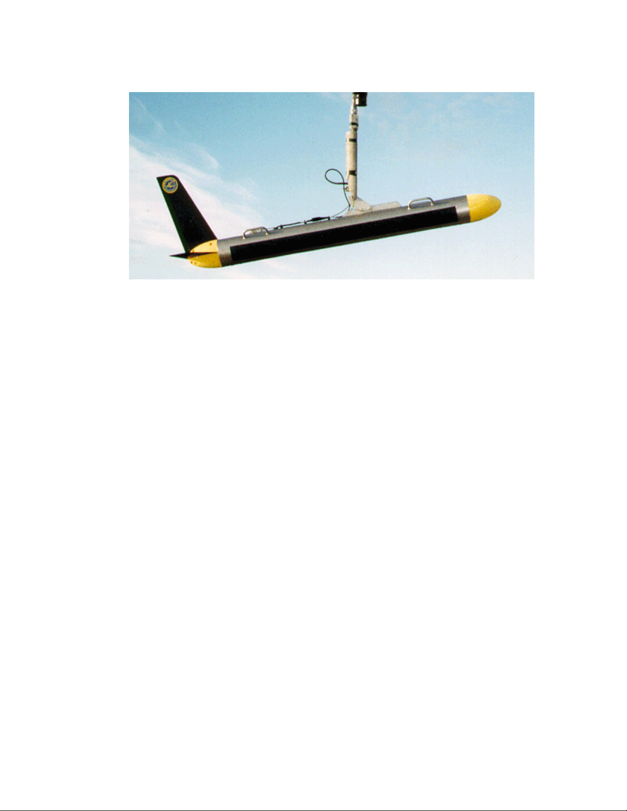
1.3.2 Subsurface Equipment
The subsurface equipment comprises the towfish, as shown in Figure 1-2, and a
tow cable.
Towfish. The Towfish consists of a negatively buoyant tow body containing
port and starboard sonar transducers, processing and control electronics for
sonar operation, a downlink demultiplexer for control signals, and an uplink
multiplexer for sonar and auxiliary sensor data.
Tow Cable. The tow cable is a complete assembly consisting of a coaxial tow
cable with a copper conductor, an electro-mechanical termination on the
towfish end, and an electrical underwater connector . The tow cable is available
1-4 CHAPTER 1 Overview
in either a lightweight polyurethane jacketed Kevlar reinforced design or a
double armored steel design. The lightweight design is used for operations
with cable lengths of 300 meters and under . The double armored design is used
for cable lengths longer than 300 meters.
Figure 1-2: Towfish
1.4 Theory of Operation
This section provides a detailed functional description of the Series 5000 Sonar
System operation.
1.4.1 Introduction
The Series 5000 Sonar System is a simultaneous multiple swath-forming,
side-looking sonar intended for high speed, high resolution survey use. The two
primary drawbacks of conventional side-looking sonars, along-track resolution
and towing speed limitation, have been addressed by simultaneously forming
multiple dynamically focused beams per side, per ping. This allows greater towing
speeds without the usual loss of bottom coverage, while maintaining high
resolution. Also, the formed swaths are focused dynamically with across-track
range, thereby offering an inherently improved along-track resolution over
unfocused systems.
Series 5000 Sonar System Operations and Maintenance Manual P/N 11210060, Rev. 16

Theory of Operation 1-5
The Series 5000 departs from previous multibeam systems in that the swath
forming process is implemented digitally using digital signal processing (DSP),
rather than analog delay lines, phase shifters, or multipliers and adders. The
primary advantage of this technique is a reduction in the size and weight of the
towfish. This affords a concomitant reduction in the size of the required survey
vessel and ancillary equipment, such as a winch and crane. Other advantages
include more flexibility in the swath processing, allowing software control of
operating parameters. Previously this would have required hardware changes.
The Series 5000 architecture is composed of the towfish, the tow cable, the
computer, and the TPU. The towfish contains the transducer arrays and electronic
subsystems for transmission, reception and data acquisition, and telemetry. The
towfish also includes standard and optional sensors for the monitoring of towfish
position and motion dynamics, pressure, depth and altitude (acoustically
measured), temperature, and other pertinent information.
The tow cable is simply a coaxial cable that provides power transfer and duplex
communications between the towfish and the TPU.
The TPU processes the data from the towfish, producing multiple simultaneously
focused swaths. The TPU outputs this data via a proprietary parallel port. Sonar
processor control of the TPU is done via the local area network (LAN).
1.4.2 Towfish
The towfish is composed of the towfish housing, which has external brackets for
cable attachment, the transducer arrays (one for each side), the nose cone, the tail
section, and a pressure housing containing attitude and environmental sensors and
electronics. In a typical operation the towfish is towed behind the survey vessel by
means of the tow cable. The depth at which the towfish runs below the surface of
the water is a function of both the length of the deployed cable and the tow speed.
NOTE The transducers are side specific and are not interchangeable.
The two transducer arrays are each composed of 12 piezoelectric ceramic
sub-arrays that operate as both transmit and receive elements. Each set of
12 sub-arrays is arranged into a continuous line array spanning an overall aperture
of 1.2 meters.
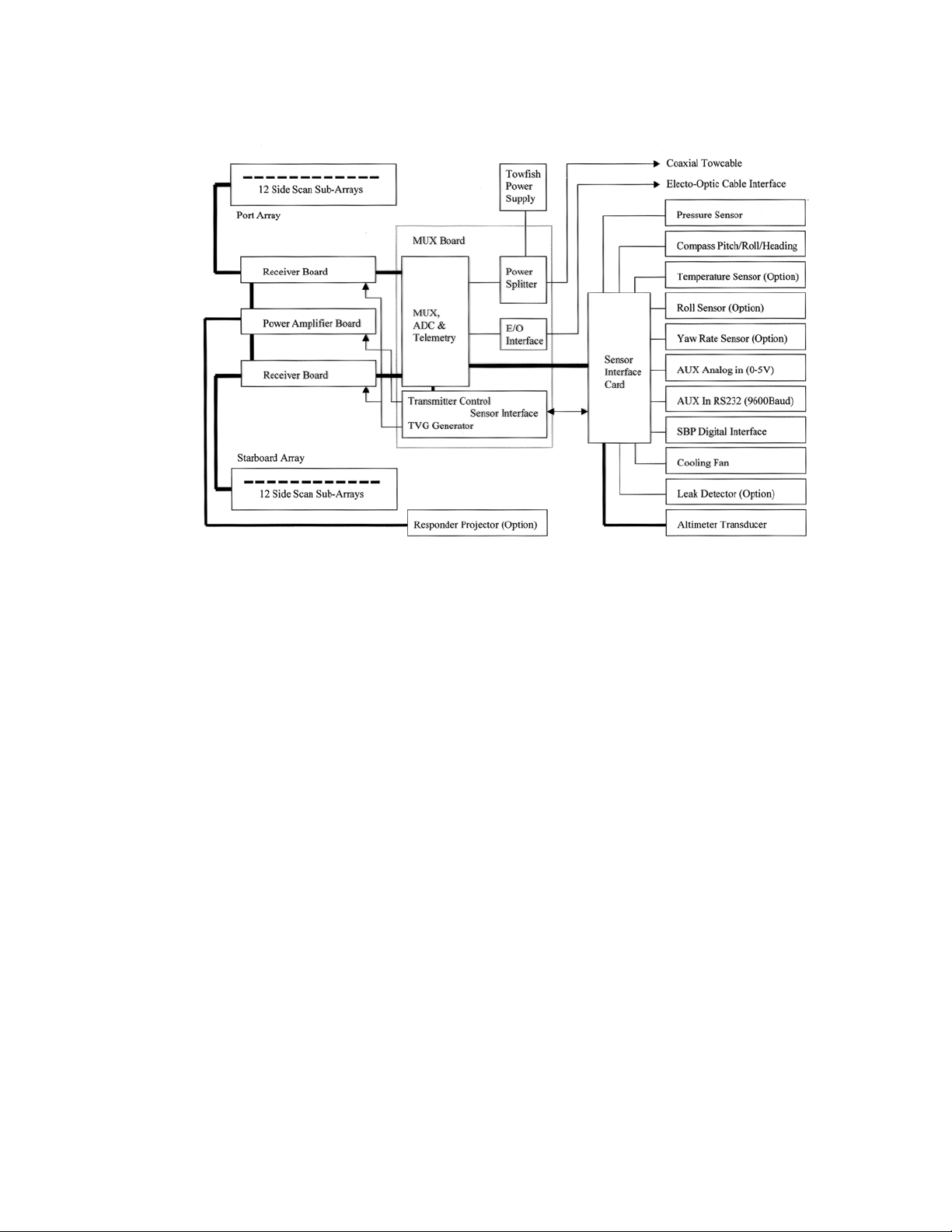
The towfish electronics is divided into five individual boards: a T ransmitter board,
two Receiver boards, a Sensor Interface board, and a Multiplexer board. A block
diagram of the towfish is shown in Figure 1-3.
1-6 CHAPTER 1 Overview
Figure 1-3: Towfish Block Diagram
Transmitter board.
The Transmitter board produces a transmit pulse, at the
start of a swath, that illuminates the sea floor over a defined footprint. The
pulse length is nominally 100 µs. The Transmitter board is composed of six
individual transmitting channels, each of which is connected to two sub-arrays
of both the port and starboard transducer. The six transmitters operate at a
center frequency of 455 kHz while independently providing phase modulation
to reduce coherence in the transmit pulse to mitigate the effects of speckle in
the received data. The transmitters are Class-D switching types coupled
through a double tuned transformer to the transducer sub-arrays.
The Transmitter board also contains two additional auxiliary transmitters, one
for an optional externally mounted responder and one for the downward
looking altimeter.
Receiver boards. The Receiver boards process the backscatter information
by applying fixed gain, time varied gain (TVG) and frequency filtering to the
input voltage signals received from the individual sub-arrays in the transducer
arrays. There are two Receiver boards, one for the port array and one for the
starboard array.
The Receiver boards first process the transducer data by isolating the input
preamplifier electronics from the high voltage transmit signal via a
transmit/receive (T/R) switch. The T/R switch is automatic and requires no
intelligent control. After the transmit waveform has decayed, the switch closes
Series 5000 Sonar System Operations and Maintenance Manual P/N 11210060, Rev. 16

Theory of Operation 1-7
to allow the receive signals to enter a fixed gain low noise preamplifier stage.
The output of the preamplifier is input to a voltage controlled amplifier (VCA)
which performs the TVG function. The gain versus time relationship, TVG,
that is applied identically to all channels is digitally synthesized from a
predefined curve stored in a PROM on the Multiplexer board. Provision has
been made for the storage of alternate TVG curves but in practice it has been
found that the use of these has been limited to test procedures.
Each of the receiver channels is bandpass filtered with tightly matched filters
providing a -3dB bandwidth of 20 kHz, centered at 455 kHz. The filtered
signal is then output to the Multiplexer board for subsequent sampling.
Sensor Interface board. The Sensor Interface board conditions sensor data
from the compass board, depth pressure sensor, altimeter, and optional devices
for subsequent multiplexing and transmission to the TPU.
Multiplexer board. The Multiplexer board digitizes the signals from each of
the transducer sub-array channels along with the signals from the sensors,
encodes the data, and transmits a high baud rate digital data stream to the TPU
via the tow cable. The Multiplexer board also receives the trigger signal and
command messages which instruct the T rans mitte r board to fire the arrays and
configure aspects of towfish operation. The Multiplexer board also acts as a
motherboard for the other boards providing the connections and distributing
power.
The Multiplexer board uses a proprietary sampling scheme that preserves the
phase of the individual channel signals, but only requires a single A/D
converter, thereby reducing cost and power consumption while eliminatin g the
phase mismatch between converters of alternate dual converter schemes. The
output of the A/D is input to the data encoder and converted to serial data for
subsequent transmission up the tow cable.
A full duplex hybrid allows data transmission up the cable while
simultaneously receiving the FSK trigger signals and power. The downlink
signals are input to FSK demodulators, and the baseband outputs are routed to
the Transmitter board, indicating when to fire the main array, and to a micro
controller that handles towfish configuration.
Towfish connector. The towfish connector pinouts are shown in Table 1-1,
and the connector is shown in Figure 1-4. Only two pins are used.
Table 1-1: Towfish Connector—at Towfish
PIN NO. LABEL FUNCTION
1
2 Shield Power and data return
Power/Data +200 VDC power and multiplexed data
1-8 CHAPTER 1 Overview
Figure 1-4: Towfish Connector—at Towfis h
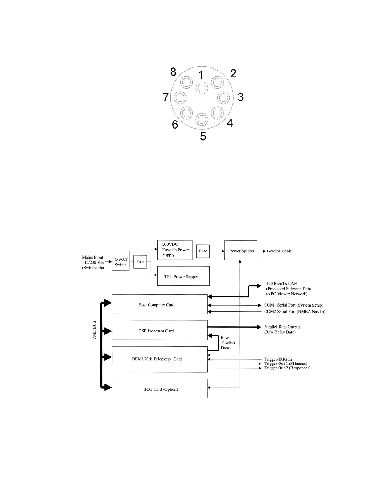
1.4.3 Transceiver and Processing Unit
The TPU provides signal processing along with the system control and data
telemetry functions. The TPU is composed of three circuit boards: an embedded
CPU board, a Demultiplexer board, and a Digital Signal Processor (DSP) board.
The TPU also contains a 200-volt towfish power supply and a TPU power supply.
A block diagram of the TPU is shown in Figure 1-5.
Figure 1-5: TPU Block Diagram
Series 5000 Sonar System Operations and Maintenance Manual P/N 11210060, Rev. 16
 Loading...