

Klegg electronic M6 501P User Manual

DIGITAL DECODER

Acknowledgement & Trademark
Acknowledgment & Trademark
All contents are subject to change at any time without notice. No
responsibility is assumed for its use; or for infringements of patents
or other rights of third parties and no patent or license is implied
hereby. All trademarks are the property of their respective owners.
Manufactured under license from Dolby Laboratories. "Dolby",
"ProLogic " and the double-D symbol are trademarks of Dolby
Laboratories. Confidential Unpublished Works. (c)1992 - 1997
Dolby Laboratories, Inc. All rights reserved.
Manufactured under license from Digital Theater Systems, Inc. US
Pat. No. 5,451,942, 5,956,674, 5,974,380, 5,978,762 and other
world-wide patents issued and pending. “DTS” and “DTS Digital
Surround” are reg istered trademarks of Digital Theater Systems, Inc.
Copyright 1996, 2000 Digital Theater Systems, Inc. All Rights
Reserved.
Sony and PlayStation? are trademarks of Sony Corporation.
Nintendo? is a trademark of Nintendo America, Inc.
FCC Compliance Statement
The equipment has been tested and found to comply with the limits for a Class B digital
device, pursuant to Part 15 of the FCC Rules. These limits are designed to provide
reasonable protection against harmful interference in residential installation. This
equipment generates, uses, and can radiate radio frequency energy and, if not installed and
used in accordance with the instructions, may cause harmful interference to radio
communications. However, there is no guarantee that interference will not occur in a
particular installation. If this equipment does cause interference to radio or television
reception, which can be determined by turning the equipment off and on. The user is
encouraged to try to corr ect the interference by one or more of the following measures:
1

?? Reorient or relocate the receiving antenna.
?? Increase the separation between the equipment and receiver.
?? Connect the equipment into an outlet on a circuit different from that to which the
receiver is connected.
?? Consult your dealer or an experienced radio/TV technician for help.
Notice
This device complies with Part 15 of the FCC rules. Operation is subject to the following two
conditions: (1) this device may not cause harmful interference, and (2) this device must
accept any interference received, including interference that may cause undesired operation.
Shielded cables and I/O cords must be used for this equipment to comply with the relevant
FCC regulations.
2

Table of Contents
Introduction ----------------------------------------------------------------- 4
Checking Package Contents --------------------------------------------------- 4
M6 501P Features ----------------------------------------------------------- 5
Important Safety Instructions -------------------------------------------------- 5
Installation ------------------------------------------------------------------6
M6 501P Front Panel ---------------------------------------------------------7
M6 501P Rear Panel --------------------------------------------------------- 8
Connecting M6 501P (with External Power Amplifier) ----------------------------- 9
Connecting M6 501P (to the Klegg M6 501R Theater System) --------------------- 10
M6 501P Remote Control ----------------------------------------------------- 12
M6 501P Operation
LCD & LEDs ------------------------------------------------------------------------- 13
LCD Display ------------------------------------------------------------------------- 14
Mode Selection ---------------------------------------------------------------------- 14
Input Selection ----------------------------------------------------------------------- 15
Test Mode --------------------------------------------------------------------------- 16
Mute Mode -------------------------------------------------------------------------- 17
Master Volume Control --------------------------------------------------------------- 17
Balance Setting ---------------------------------------------------------------------- 18
Delay Calibration --------------------------------------------------------------------- 19
Time Delay Adjustment of Center Channel Speaker ------------------------------------- 20
Time Delay Adjustment of Surround Speakers ------------------------------------------ 21
Pro Logic Mode ---------------------------------------------------------------------- 22
Speaker Mode with Bass Manager ------------------------------------------------------23
Saving Presets ----------------------------------------------------------------------- 25
Loading Presets ---------------------------------------------------------------------- 26
Sound Field Processing -------------------------------------------------------------- 27
Equalization -------------------------------------------------------------------------- 28
DRC (Dynamic Range Compression) -------------------------------------------------- 29
Resetting ---------------------------------------------------------------------------- 30
Troubleshooting --------------------------------------------------------------31
Warranty ------------------------------------------------------------------- 32
In case of an insurance claim, please make sure you record the Model Number and Serial
Number printed on the real panel of the cabinet. The space below is provided this
information.
Model Number: Serial Number:
Purchase Date: Dealer Name:
3

Introduction
Thank you for purchasing the Klegg M6 501P Surround Sound Decoder. This versatile audio
surround sound system has been precisely designed to bring you the most advanced
surround modes including DTS, Dolby Digita l & Dolby Pro Logic. This system will reproduce
six discrete channels of encoded sound tracks with true fidelity and sonic excellence. The
M6 501P automatically detects the type of signal present at each input and decodes it based
on the original encoded software. The M6 501P allows you to connect virtually any audio
input source such as TV, VCR, CD- ROM, DVD Player, LD Player, Stereo Receiver, PC and
Game Consoles (Nintendo?, Sony PlayStation?, and SEGA?). The Klegg M6 501P is a
truly a dynamic multimedia theater center.
Checking Package Contents
Carefully unpack the Klegg M6 501P Surround Sound Decoder from the package and locate
its contents.
M6 501P Surround Sound Decoder x 1
M6 501P Owner’s Manual x 1
M6 501P Remote Control x 1
AC Adapter for Decoder (DC 12V, 1A) x 1
Note: Be sure to inspect the M6 501P for signs of damage resulting from shipping and
handling. If you notice any damage or find any items missing, please contact your local
dealer immediately.
4

M6 501P Features
- DTS
- Dolby Digital
- Dolby Pro Logic
- Bass Management
- Sound Field Processing
- Equalization
Important Safety Instructions
To ensure your safety, please read these instructions before operating this unit.
1. Note all instructions and warnings marked on the unit.
2. Always use the correct line voltage. Please refer to page 6 and locate the correct power
requirement for your area. Please note that different operating voltages may require the
use of different adapters.
3. Do not install the unit in an unventilated rack or directly above heat producing
equipment such as power amplifiers.
4. Do not block the openings on either side of the case.
5. To avoid shock or fire hazard, do not expose the unit to rain or moisture or operate it
where it will be exposed to water.
6. Do not attempt to operate the unit if it has been dropped, damaged, exposed to liquids,
or if it exhibits a distinct change in performance indicating the need for inspection.
7. Only qualified service personnel should open this unit.
8. Removing covers will expose you to hazardous voltages.
9. Do not overload wall outlets or extension cords as this can result in a risk of fire or
electrical shock.
10. Route power supply cords so that they are not likely to be trodden on or pinched by
items placed on or against them, paying particular atten tion to plug fittings at the wall
outlets and at the point at which they exit from the unit.
5

Safety Voltage Chart:
The following chart details the correct AC adapter for your country:
Device
M6 501P
Voltage Frequency
AC 100 V 50/60 Hz DC 12V, 1A Japan
AC 120 V 60 Hz DC 12V, 1A
AC 230 V 50 Hz DC 12V, 1A Europe/UK
Input
Output Area
North America/
Taiwan
Installation
?? Turn off any electrical or computer device that you plan to connect to the M6 501P.
?? Carefully unpack the M6 501P and its accessories from the transit packaging.
?? Place the M6 501P on a flat, stable surface, preferably on a TV shelf or similar. Allow at
least 10cm clear on all sides of the unit for ventilation.
?? Locate the M6 501P near your source equipment so you can use the shortest possible
interconnect cables. Keep your M6 501P away from moisture sources such as open
windows and heat sources such as hot air ducts or radiators. Also, keep the unit away
from direct sunlight since it could interfere with the remote control sensor.
?? The M6 501P Surround Sound Decoder has been designed to be ultimately flexible
accepting both digital and analog audio signals from CD Players, VCR, DVD players, TV
monitor, Computer and Game Consoles (Nintendo N64, Sega Dream Cast, SONY
PlayStation II etc.)
?? The M6 501P can also be connected to an external amplifier, or the Klegg M6 501R
Amplified Home Theater Speaker System as detailed on page 9 and 10.
6
de frequency range that contains bass signals between 20Hz to 120Hz. A
channels should be set to narrow frequency bandwidth and should display GREEN (see
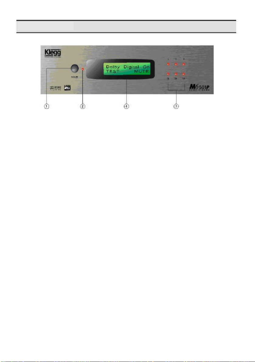
M6 501P Front Panel
1. The POWER Button
This button turns M6 501P ON or OFF.
2. The POWER Indicator
This LED lights up when you plug in DC-12V.
3. Speaker Configuration LEDs
Each LED represents the status of an individual channel. When a particular channel is
active, the LED lights up. A RED LED light means this particular channel has been set
to output a wi
GREEN LED light means this particular channel does not contain the bass signal
between 20Hz to 120Hz. When connecting to the Klegg M6 501R Home Theatre
Speaker System the Subwoofer channel should be the only RED LED. All other
page 23).
4. Front Panel Display
This display provides you with important information regarding system status and
settings. It is imp ortant to be familiar with all the indicators on the display in order to
ensure correct operation of the system.
7
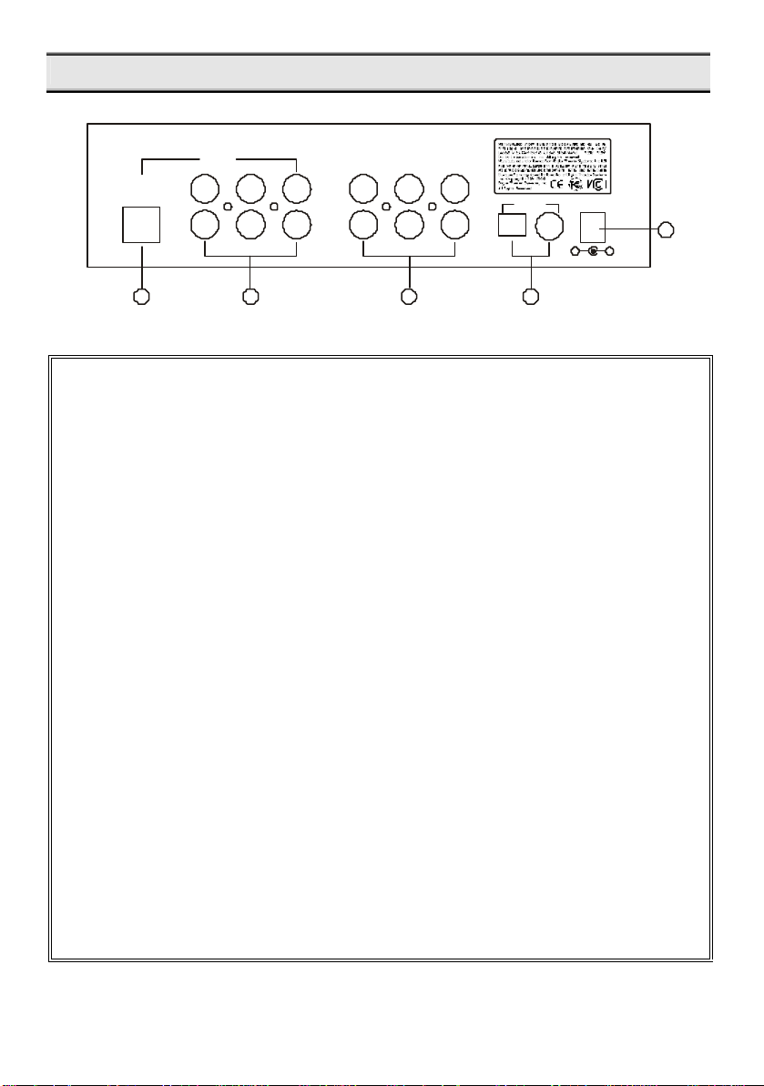
M6 501P Real Panel
DC+12V
3
415
+
_
(c)
OUTPUT
L
G9
SL
R
SRCSW
2
L
R
M6 501P Real Panel
1. G9 Audio Output:
This output feeds 6 channels audio signals; L (Front Left), R (Front Right), SL
(Surround Left), SR (Surround Right), C (Center) & SW (Subwoofer) to the matching
inputs on a control center or power amplifier via G9 (DIN) cable.
2. Main Outputs:
The Six outputs feed audio signals to the matching inputs on a control center or
power amplifier.
L (Front Left)
R (Front Right)
SL (Surround Left)
3. Auxiliary and Line Inputs:
These inputs accept signals from stereo analog signal sources.
4. S/PDIF Digital Inputs:
M6 501P accepts two types of digital inputs. One optical input and another coaxial
input. Connect the digital outputs of the sound sources to these inputs.
5. DC 12V Power Input:
Connect the M6 501P’s adapter to an AC outlet. Please refer to page 6 to determine
the correct voltage in your area.
LINEAUX 1AUX 2
L
L
S/PDIF
R
R
SR (Surround Right)
C (Center)
SW (Subwoofer)
8
S/PDIF
DC+12V
LINE
Coaxial
Digital
Audio Out
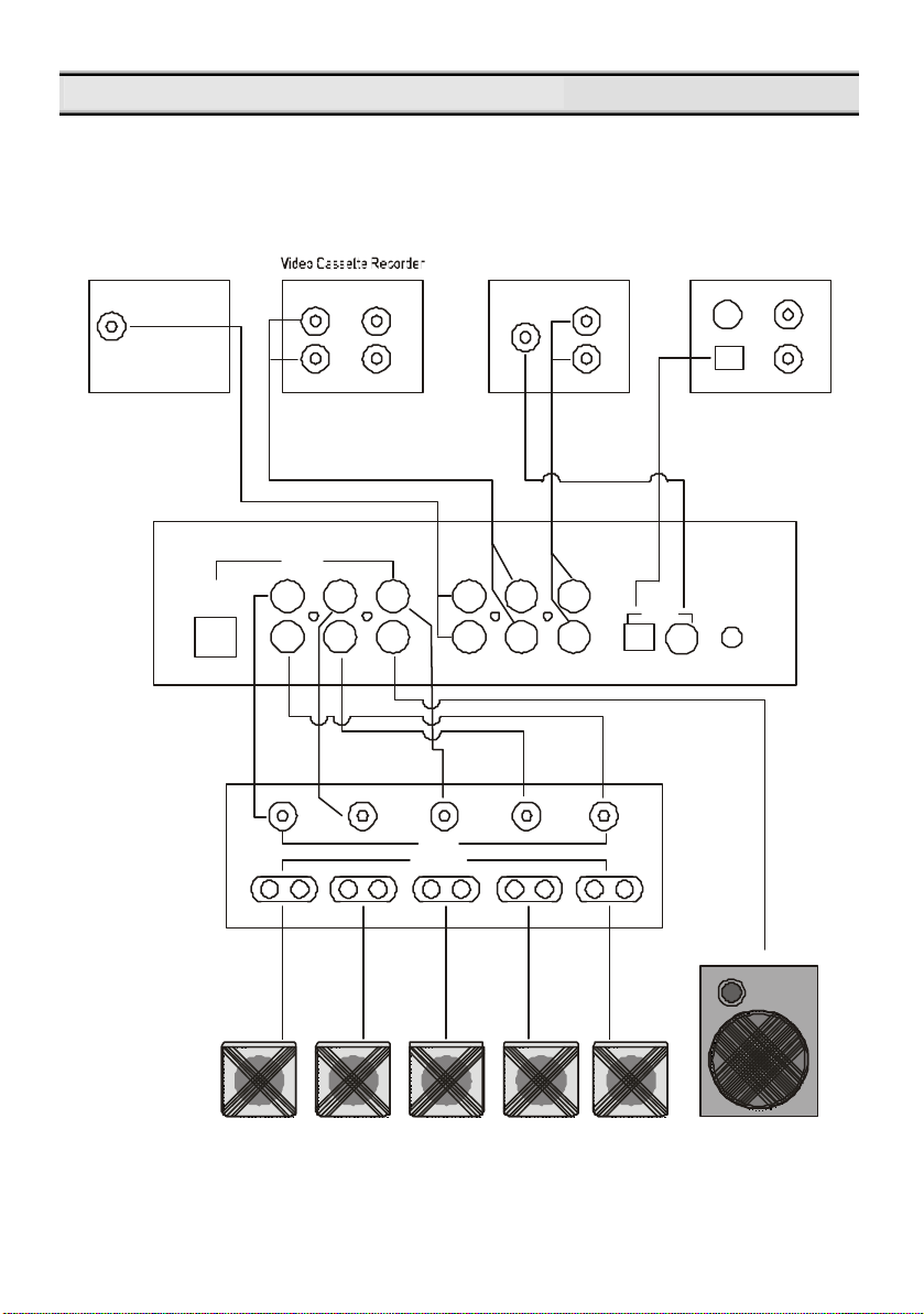
CD player
DVD Player
+_+_Left
Surround
Surround
External
Amplifier
Output
Powered
Subwoofer
Connecting M6 501P (with External Power Amplifier)
Game Consoles
Audio Out
Phone Jack
G9
Audio Out
Play
L
R
L
R
L
R
Rec
SLSRC
digital Output
AUX 1AUX 2OUTPUT
L
L
SW
R
R
L
R
L
R
Coaxial
Optical
L
R
L SL C SR R
Input
_
+
+
Left
_
_
+
Center
Right
9
Right
 Loading...