

Kleenmaid TX768A User Manual

model : TX768A


3
Contents
Pages
Unpacking your machine............................................................................ 4 & 5
Installing the machine ................................................................................ 5 & 6
Connecting up your machine .................................................................... 6 & 7
Fabric care symbols .................................................................................. 8
Sorting the washing.................................................................................... 9
Fabric care advice ...................................................................................... 9
Dealing with difficult stains ........................................................................ 10
Loading the laundry and the washing powder/liquid ................................ 11
Selecting a wash programme ....................................................................12 to 14
Automatic safety devices .......................................................................... 14
Programme examples ................................................................................ 15
Routine maintenance..................................................................................16 to 18
Possible incidents ...................................................................................... 19
Warranty and Service ................................................................................ 20
Before using your machine, carefully read these instructions which will
enable you to quickly become familiar with the way it works.
4
Unpacking your machine
BEFORE ATTEMPTING TO USE THE MACHINE, YOU MUST FOLLOW THE PROCEDURE
DESCRIBED BELOW
These operations involve removing the metal transit bracket and the blocks which
immobilise the tank of your machine during the transportation, as well as the supports
which hold up the hoses and the electric cable.
These operations, known as "unpacking", are necessary for your machine to
operate correctly and also for complying with current safety standards.
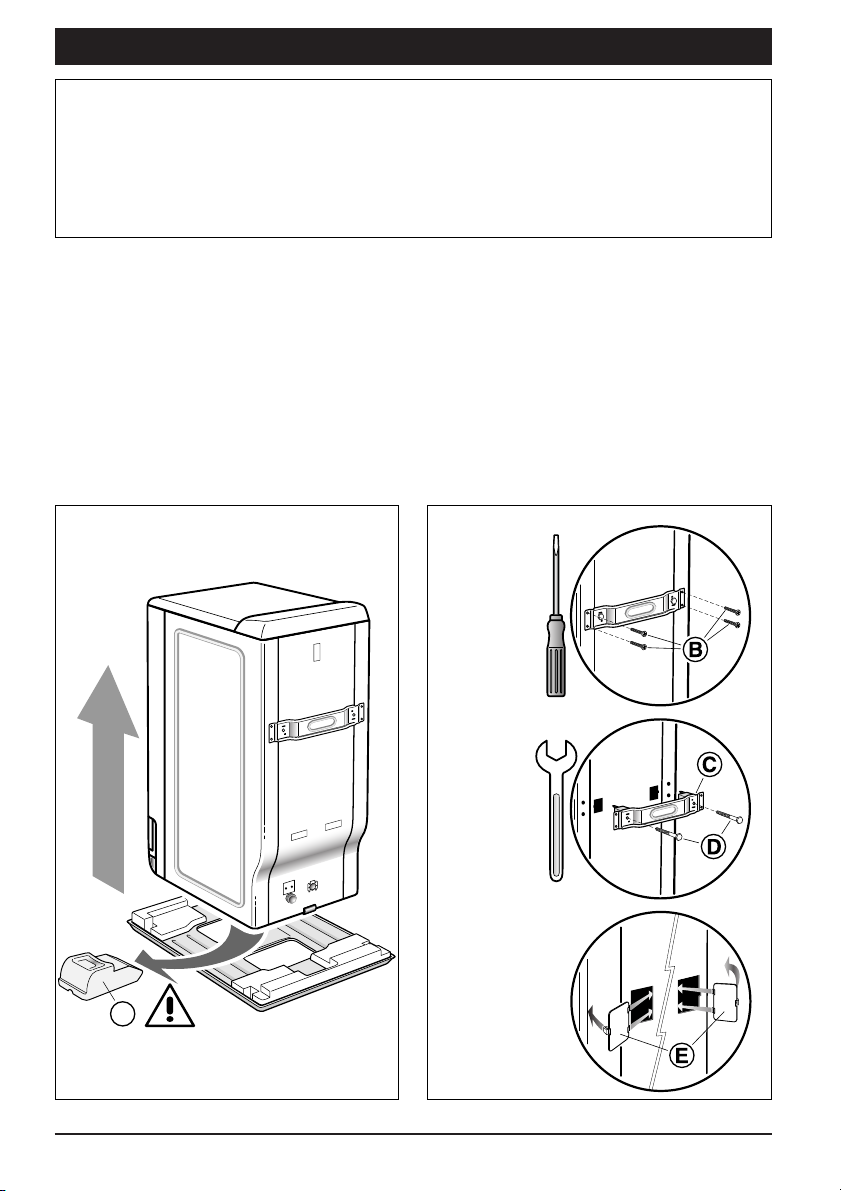
1 - Remove the washing machine from its
base (check that the block «A» that
retains the motor is not stuck under
the machine) (Diagram 1)
2 - Remove the four screws «B» with a
screwdriver (Diagram 2.1)
3 - Remove the bracket «C» by removing
the two bolts «D» with a 13 mm spanner
(Diagram 2.2)
(Make sure that the two plastic
spacers attached to the bar are
removed at the same time).
Replace screws «B» in their original
position.
4 - Blank off the two holes using the plugs
«E» (provided in bag of accessories)
(Diagram 2.3)
Diagram 1 Diagram 2.1
Diagram 2.2
Diagram 2.3
13
1
1
2
2
A

5
Unpacking your machine
Please keep all packing components as they must be replaced if the machine is
to be shipped elsewhere
All these parts and the components of your machine are made of recyclable
materials. Please bear this in mind when the time comes to dispose of your machine
Your machine was inspected before leaving the factory. You may therefore find traces
of water in the tank or in the detergent compartment
Installing the machine
We advise against installing your machine on a carpeted floor. If this is unavoidable,
take all precautions to avoid preventing air circulation at the base, to ensure that
the internal parts are well ventilated.
Machine location
If you locate your machine next to another
appliance or an item of furniture, you should
leave space between them to allow air to
circulate (Diagram 5).
Diagram 5
5 - Remove the block that immobilises the
drum and tub (Diagram 3).
To do this:
- raise the machine lid;
- if your machine comes with a packing
wedge «F», remove it;
- remove the block «G» by rotating it
through 90°;
- open the doors of the drum which are
locked in the low position, by pushing
both flaps at the same time.
6 - Lift up the hoses support clamps
➀
and
do not fall to block the holes using
plugs
➁
(provided in the accessories
bag) (Diagram 4).
Diagram 3
a
b
a
b
➀
➁
Diagram 4
F
G
6
Installing the machine
Connecting up your machine
Moving the machine
using the castors
To extend the castors, move the lever at
the bottom of the machine from right to left
(Diagram 6).
The machine should not be used while
standing on its "front" castors: do not forget
to return the lever to its original position.
Levelling
Use a spirit level to check that the ground
is horizontal: the maximum allowable slope
is 2° which gives a difference in height of
about 1 cm across the width of the machine
and 1.5 cm from front to rear.
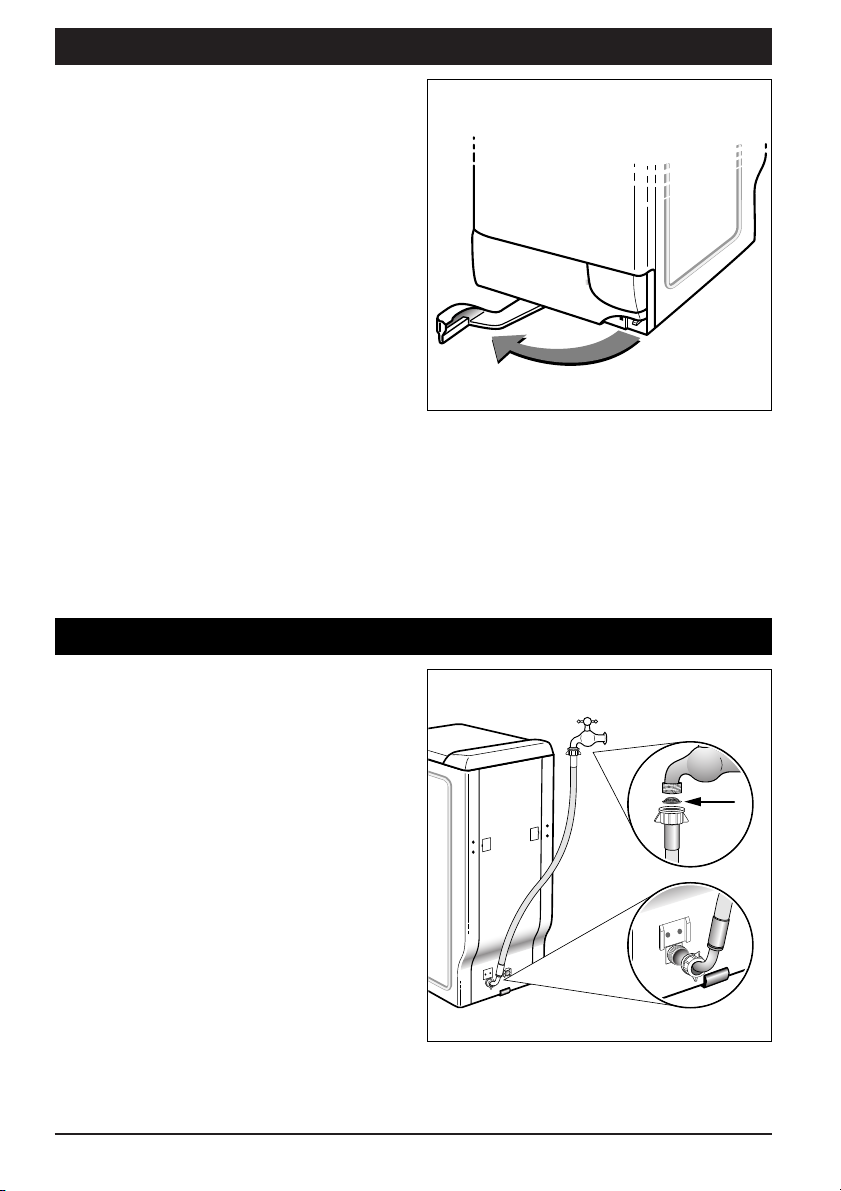
Cold water supply
Connect up the hose (Diagram 7):
- connect the 90° elbow end to the union
at the back of the machine;
- connect the other end to a tap fitted with
a threaded end diameter 3/4 BSP, not
forgetting to insert the filter washer
supplied in the bag of accessories.
Diagram 6
Diagram 7
Water inlet :
- Minimum water pressure: 70 kPa
- Maximum water pressure : 1000 kPa
 Loading...