

Page 1

Rangehood
Collection
Instructions for Use
and Warranty Details
MENHIR
Island Rangehood
Page 2

the best you can own.
Congratulations on the purchase of your new Kleenmaid
rangehood. This
has been designed and manufactured to give you years of reliable performance.
the kleenmaid story.
More than one million Australians enjoy using Kleenmaid appliances daily. Selected because of
their unique design, outstanding performance, excellent quality and unquestionable reliability,
each one is value-for-money, 100 per-cent guaranteed and at the top of its class.
attention to detail.
We are proud of our reputation for product innovation and service excellence. By dealing direct, we
can ensure that you consistently receive a high standard of customer service.
Free delivery, dedicated customer service and after-sales service team plus free kitchen design and
planning seminars are just a few of the ways we are setting new benchmarks for customer service
and experience.
satisfaction guaranteed.
Your new
appliance is covered by a written five-year parts and labour warranty,
guarantee, and a unique best value guarantee.
best results.
For best results, carefully read the enclosed instructions on how to install your new rangehood.
Correct installation will avoid delays and unnecessary service calls.
This booklet provides you with comprehensive information to help you get to know the controls and
the features of your new rangehood.
congratulations
rangehood
1
no lemon
Page 3
INSTRUCTION ON MOUNTING AND USE
7
6
1
3
1
2
5
4
2
g
g
j
i
h
g
g
4
3
A
2
Page 4
INSTRUCTION ON MOUNTING AND USE
3
4
273
244
273
214
14,5
190
4
4
4
4
4
6
6
7
5
6
9
7
7
7
8
8
7
2
2
2
2
5
3
Page 5

INSTRUCTION ON MOUNTING AND USE
G
13a
13b
F
13a
10F
13b
10A
13a
14a
14b
14a
14b
12
12
6
11
11
4
Page 6

17
INSTRUCTION ON MOUNTING AND USE
18-
5
18-
6
16b
18-
18-
16b
18-
1
2
3
17
17
18-
18-
7
18-
4
8
16a
8
7
4
3
2
1
6
5
18
7
5
Page 7

INSTRUCTION ON MOUNTING AND USE
X
X
19
20
19
8
6
Page 8

INSTRUCTION ON MOUNTING AND USE
Consult the designs in the front pages referenced in the text by
alphabet letters. Closely follow the instructions set out in this
manual. All responsibility, for any damages or fires caused by not
complying with the instructions in this manual, are the responsibility
of the user.
The Rangehood must be placed at a minimum distance of 50 cm from
the cooking plane for electric cookers and 65cm for gas or mixed
cookers.
The hood can be installed above these heights but for optimum
performance it should be installed at the distance quoted for the
appropriate heat source.
Do not tile, grout or silicone this appliance to the wall. Surface
mounting only.
The hood is equipped with a top air outlet B for discharge of fumes to
the outside (Ducting version – exhaust pipe and pipe fixing clamps
not provided).
If it is not possible to discharge cooking fumes and vapour to the
outside, the Rangehood can be used in the filter version, fitting an
activated carbon filter and the deflector F
on the support (bracket) G, fumes and vapours are recycled through
the top grille H by means of an exhaust pipe connected to the top air
outlet B and the connection ring mounted on the deflector F (exhaust
pipe and pipe fixing clamps not provided).
The models with no suction motor only operate in ducting mode, and
must be connected to an external suction device (not supplied).
Expansion wall plugs are provided to secure the Rangehood to most
types of walls/ceilings. However, a qualified technician must verify
suitability of the materials in accordance with the type of wall/ceiling.
The wall/ceiling must be strong enough to take the weight of the
Rangehood.
Do not tile, grout or silicone this appliance to the wall. Surface
mounting only.
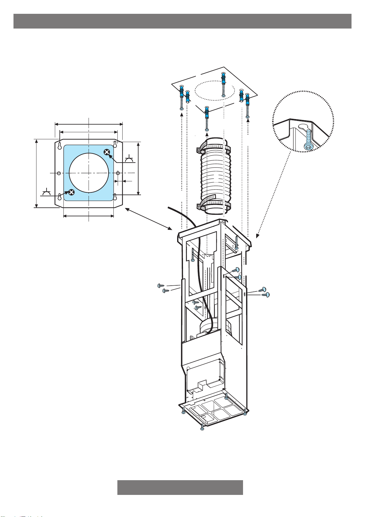
Installation - Fig. 5-6-7-8
Preliminary information for installing the Rangehood
During electrical connection ensure the power supply is disconnected
at the domestic main switch.
1. Adjust extension of the Rangehood support structure, as the final
height of the Rangehood depends on this, and remember that
with installation completed the Rangehood must be at least 50 cm
above the cook-top for electric cookers and 65 cm for gas
cookers.
2. Fix the two sections of the structure using 8 screws.
3. Place the ceiling hole diagram directly above the cook-top (the
center of the diagram must match the center of the cook-top and
the edges must be parallel to the sides of the cook-top – the side
of the diagram with the wording FRONT corresponds to the
control panel side). Prepare the electrical connection.
4. Drill as shown (6 holes for 6 wall plugs – 4 plugs for fixture), screw
the outer screws leaving a space of about 1 cm between the
screw head and the ceiling.
5. Fit an exhaust pipe inside the truss and connect it to the motor
compartment connection ring (exhaust pipe and fixing brackets
are not supplied).
6. Hook the frame onto the 4 screws (see step 4).
CAUTION! The side of the truss with connection box corresponds
to the side of the control panel with Rangehood assembled.
7. Tighten the 4 screws.
8. Insert and tighten another 2 screws in the remaining free holes for
secure fixing.
9. Carry out the electrical connection to the mains power supply,
7
only turn on the power supply upon completion of assembly.
10. For extractor versions (10A), connect the other end of the exhaust
pipe to the flue.
For filter versions (10F), fit deflector F to the truss and secure it
to the bracket supplied using 4 screws, then connect the exhaust
pipe to the connection ring located on the deflector.
11. Remove the fixing tabs placed on the lower part of the chimney
flue, set aside the tabs and screws.
12. Apply the tabs to the inside of the upper section of the chimney
flue using one screw for each tab.
13. Fix the upper sections of the telescopic chimney flue (13a) to the
pylon (13b).
The upper sections are recognizable by the air exit perforations
for use in the filter version.
14. Block the sections with 2 screws (14a) to be inserted on the tabs
already mounted on one section of the chimney flue (14b – see
also the mounting sequence 11 -12).
15. Remove the grease filter and slide in the lower section of the
Rangehood (during this operation slightly widen the two sections
to ease the insertion).
The front side of the Rangehood is recognizable by the slit
opening provided for the control panel.
Attention! During this operation ensure to extract the control
panel plate and the electrical connection cables for the lamps
through the slit opening.
16. Fix the lower section of the Rangehood to the pylon from the
bottom using 6 screws (16a), and on the sides using 4 screws
(16b).
17. Introduce the cables CONNECTED to the lamps and connect the
control panel to the plate.
ATTENTION! THE PLATE CABLE CONNECTOR IS
PROVIDED WITH A SIDE PIN THAT MUST COINCIDE WITH
THE PERFORATION FOUND ON THE SIDE OF THE
CONNECTOR LOCATED ON THE BACK OF THE CONTROL
PANEL.
18. The double sided adhesive tape supplied should be cut into 8
segments, then remove the protection covering from both sides
and apply the segments close to the screws that fix the chimney
flues to the structure (see illustration for correct positioning).
19. Apply the 4 masks (supplied) to cover the fixing points of the lower
sections of the chimney flue (ATTENTION THE MASKS FOR
THE LOWER CHIMNEY FLUE ARE RECOGNIZABLE BY THEIR
NARROWER WIDTH).
The wider masks are to be used for the upper chimney flue, and
should be cut to size.
20. Hook the control panel to the opening slit so that the ON/OFF
light switch is facing downwards.
Remount the grease filter, turn on the power supply via the central
electrical panel and check that the Rangehood functions correctly.
Only for products supplied in stainless steel and aluminum:
Remove the protective covering taking care not to damage the metal
and finish (glazing).
Electrical connection
The electrical tension must correspond to the tension noted on the
label placed inside the Rangehood. Connect the electrical plug, where
provided, to an easily accessible outlet in conformity with local
standards in force.
Where an electrical plug is not provided (for direct connection to
electrical network) place a standards approved bipolar switch with an
aperture distance of not less than 3mm (accessible) from the contacts.
Page 9

INSTRUCTION ON MOUNTING AND USE
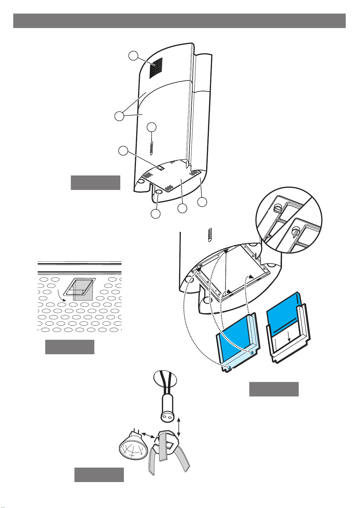
Description of the hood - Fig. 1
1 Control panel
2 Grease filter
3 Grease filter release handle
4 Halogen lamp
5 Vapour screen
6 Telescopic chimney
7 Air outlet (used for filter version only)
Operation
Description of control panel and hood operation
A. on/off light switch
B. on/off aspiration switch and minimum power
selection
B+C. medium power selection aspiration switch
B+D. maximum power selection aspiration switch
Use the high suction speed in cases of concentrated
kitchen vapours. It is recommended that the Rangehood
suction is switched on for 5 minutes prior to cooking and
to leave in operation during cooking and for approximately
D
C
B
A
the Rangehood and replacement of the filters may cause fire risks.
Therefore we recommend observing these instructions.
another 15 minutes after terminating cooking.
Maintenance
Prior to any maintenance operation ensure that the
Rangehood is disconnected from the power supply.
Cleaning
The Rangehood should be cleaned regularly internally
and externally.
For cleaning use a cloth moistened with denatured alcohol
or neutral liquid detergents. Avoid abrasive detergents.
Warning:
Failure to carry out the basic standards of the cleaning of
out).
Eliminate excess water without damaging the filter, then remove the
mattress located inside the plastic frame and put it in the oven for 10
minutes at 100° C to dry completely. Replace the mattress every 3
years and when the cloth is damaged.
Remove the filter holder frame by turning the knobs (g) 90° that affix
the chimney to the Rangehood (Fig. 3).
Insert the pad (i) of activated carbon into the frame (h) and fit the whole
back into its housing (j).
Replacing lamps - Fig. 4
Firstly check that the lamps are well cooled prior to replacing them.
Use a small screwdriver as a lever on the borders of the lamp in order
to remove the lightbulb.
Unthread the connector A.
Slide out the lightbulb to be replaced and replace with a new 12V 20W
30° Ø35 12V GU4 PHILIPS STANDARD LINE code 425409.
Carry out the replacement and mount the new lightbulb by following
instructions in the reverse.
If the lights do not work, make sure that the lamps are fitted
properly into their housings before you call for technical
assistance.
Caution
The appliance is not intended for use by young children or infirm
persons without supervision.
Young children should be supervised to ensure that they do not play
with the appliance.
Do not use the Rangehood where the grill is not correctly fixed! The
suctioned air must not be conveyed in the same channel used for
fumes discharged by appliances powered by other than electricity.
The environment must always be adequately aerated when the
Rangehood and other appliances powered by other than electricity
are used at the same time. Flambé cooking with a Rangehood is
prohibited. The use of a free flame is damaging to the filters and may
cause fire accidents, therefore free flame cooking must be avoided.
Frying of foods must be kept under close control in order to avoid
overheated oil catching fire. Carry out fumes discharging in accordance
with the regulations in force by local laws for safety and technical
restrictions.
Grease filter
This must be cleaned once a month using non aggressive detergents,
either by hand or in the dishwasher, which must be set to a low
temperature and a short cycle.
When washed in a dishwasher, the grease filter may discolour slightly,
but this does not affect its filtering capacity.
To remove the grease filter, pull the spring release handle (f) - (Fig. 2).
Charcoal filter (filter version only)
It absorbs unpleasant odours caused by cooking.
The charcoal filter can be washed once every two months using hot
water and a suitable detergent, or in a dishwasher at 65°C (if the
dishwasher is used, select the full cycle function and leave dishes
8
Page 10

warranty
and service
domestic warranty - full five year warranty
In addition to all statutor y rights which you, the Consumer, have under the relevant laws in respect of this appliance,
during the first five years of ownership as the original purchaser of this Kleenmaid appliance, we guarantee that any
fault caused by faulty material or workmanship becoming apparent will be rectified free of charge for parts and labour,
provided that all service is performed during normal working hours by Kleenmaid or their designated Agents. Where
the appliance is installed outside the normal servicing area of the above, the Purchaser must pay for the cost of
transporting the appliance to and from the Agent or the Agent’s travelling cost to and from the Purchaser’s home.
commercial warranty - one year warranty
When this appliance is installed in a commercial application, you, the Consumer, have under the relevant laws in
respect of this appliance, during your first one year of ownership as the original purchaser of this Kleenmaid appliance,
we guarantee that any fault caused by faulty material or workmanship becoming apparent, will be rectified free of
charge for parts and labour, provided that all service is performed during normal working hours by Kleenmaid or their
designated Agents. Where the appliance is installed outside the normal servicing area of the above, the Purchaser
must pay for the cost of transporting the appliance to and from the Agent or the Agent’s travelling cost to and from
the Purchaser’s home.
what these warranties do not cover
We are not responsible for any damage or malfunction unless caused by a defect in material or workmanship. This
includes but is not limited to abuse, misuse, improper installation and transportation damage. We are not responsible
for any consequential damages from any malfunction.
The Consumer must make the appliance available for servicing and shall bear any costs incurred for any
de-installation and/or re-installation required to make the appliance available for servicing. Kleenmaid is not liable for
any consequential damage incurred during de-installation or reinstallation.
warranty does not cover replacement of light globes or glass breakage due
to impact
In case of fractured glass do not use your appliance.
warranty registration
Please complete warranty details below. Please retain together with your proof of purchase document. These
documents will need to be viewed by our a member of our Service team should you request in warranty service.
service assistance
To assist you when phoning our Customer Service number to arrange a service call please complete
the following details and have them ready when you call.
Model Number _____________________________________ Date of Purchase _______________________________
Kleenmaid Store Purchased From ______________________ Date of Installation ______________________________
KLEENMAID CUSTOMER SERVICE - 1300 652 100
9
Page 11

appliances available
in the Kleenmaid range
the best products we can find.
We search the globe for products that meet our high standards of functionality, style and quality and
are proud of our innovative range sourced from countries throughout the world.
Washing Machines
Dryers
Dishwashers
Ovens
Cooktops
Outdoor Cooking Centres
Built-In Coffee Machines
Rangehoods
Freestanding Ovens and Cooktops
Sinks
Waste Disposals
Taps
Cookware
Refrigerators
Wine Cellars
Vacuum Cleaners
To find your nearest Kleenmaid Showroom
telephone 13 13 08.
10
Page 12

LI2X5A
 Loading...