

Page 1
D311IE3A
Installation Instructions
for Automatic Clothes Dryers
KEEP THESE INSTRUCTIONS FOR FUTURE REFERENCE. (If the dryer changes ownership, be sure
this manual accompanies the dryer.)
NOTE: The elec trical installation in the site shall comply wi th the latest edition of the Australian Electrical
Standards AS3000 - SAA wiring rules and such local regulations that might apply.
The gas dryer installation must conform with the local regulations and AG601, Installation Code for Gas
Burning Appliances.
Read complete Installation and Operation Instructions before using dryer.
The maximum clothes drying load (dry weight) shall not exceed 9 kg (20 pounds).
Part No. 510955
August 1999
Page 2

Page 3
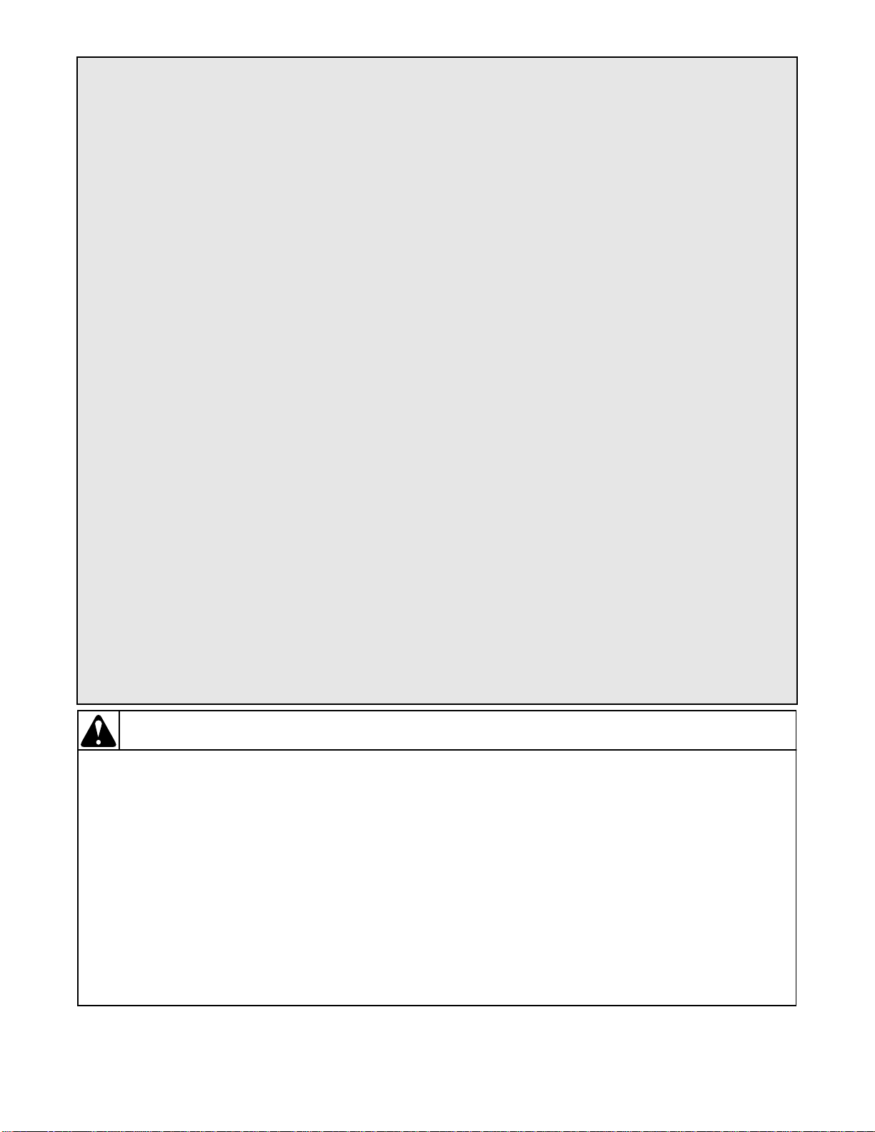
Table of
Contents
Replacement Parts .....................................................................................2
Roughing In Dimensions ...........................................................................3
Before You Start
Tools ..................................................................................................... 4
Exhaust .................................................................................................. 4
Electrical................................................................................................ 4
Gas......................................................................................................... 4
Location................................................................................................. 4
Installing the Dryer
STEP 1 (Position and Level the Dryer) ................................................ 5
STEP 2 (Connect Dryer Exhaust System).............................................5
STEP 3 (Connect Gas Supply Pipe)......................................................6
STEP 4 (Wipe Out Inside of Dryer)......................................................7
STEP 5 (Plug in the Dryer) ...................................................................7
STEP 6 (Check Installation).................................................................. 7
Heat Check .................................................................................................8
Burner Flame ............................................................................................. 8
Reversing Door Procedure ........................................................................ 9
Manufactured (Mobile) Home Installation ........................................... 10
Electrical Requirements (Electric Dryers) ............................................ 11
Electrical Requirements (Gas Dryers) ..................................................12
Gas Service ............................................................................................... 13
Location Requirements .......................................................................... 15
Dryer Exhaust Requirements
Exhaust System Materials ................................................................... 16
Make Up Air Requirements................................................................. 16
Exhaust System ................................................................................... 17
Exhaust Direction................................................................................17
Exhaust System Maintenance..............................................................18
Dryer Airflow......................................................................................18
Reduced Clearance Elbow................................................................... 18
User-Maintenance Instructions
Lubrication ........................................ ....... ........ ................................... 19
Care of Your Dryer.............................................................................. 19
Exhaust System ................................................................................... 19
Wiring Diagram (Electric Dryers)..........................................................20
Wiring Diagram (Gas Dryers) ................................................................ 21
Information for Handy Reference ..........................................................22
Installer Check .......................................................................... Back Cover
W ARNING
FOR YOUR SAFETY, the information in this manual must be followed to minimize the risk of
fire or explosion or to prevent property damage, personal injury or death.
• Do not store or use gasoline or other flammable vapors and liquids in the vicinity of this or
any other appliance.
• WHAT TO DO IF YOU SMELL GAS:
– Do not try to light any appliance.
– Do not touch any electrical switch; do not use any phone in your building.
– Clear the room, building or area of all occupants.
– Immediately call your gas supplier from a neighbor’s phone. Follow the gas supplier’s
instructions.
– If you cannot reach your gas supplier, call the fire department.
• Installation and service must be performed by a qualified in staller, service agency or the gas
supplier .
© Copyright 1999, Alliance Laundry Systems LLC
All rights reserved. No part of the contents of this book may be reproduced or transmitted in any form or by any means without
the expressed written consent of the publisher.
510955 1
W033
W052
Page 4

Replacement Parts . . .
If replacement parts are required, contact the source
where you purchased your dryer.
2 510955
Page 5
Roughing In Dimensions . . .
20.3 cm
59.7 cm
(23.5")
(8.0")
11.4 cm
(4.5")
71.1 cm
(28")
*109.2 cm (43")
*91.4 cm (36")
10.2 cm
(4.0")
1.1 cm
(0.4")
39.1 cm
(15.4")
68.3 cm
(26.9")
* WITH LEVELING LEGS TURNED INTO BASE
20.3 cm
(8.0")
11.4 cm
(4.5")
59.7 cm
(23.5")
* WITH LEVELING LEGS TURNED INTO BASE
71.1 cm
ELECTRIC DRYERS
*91.4 cm (36")
1.1 cm
(0.4")
(28")
*109.2 cm (43")
10.2 cm
(4.0")
68.3 cm
(26.9")
D616IE2A
39.1 cm
(15.4")
7 cm
(2.8")
6 cm (2.3")
3/8" NPT
GAS CONNECTION
D617IE2A
GAS DRYERS
510955 3
Page 6
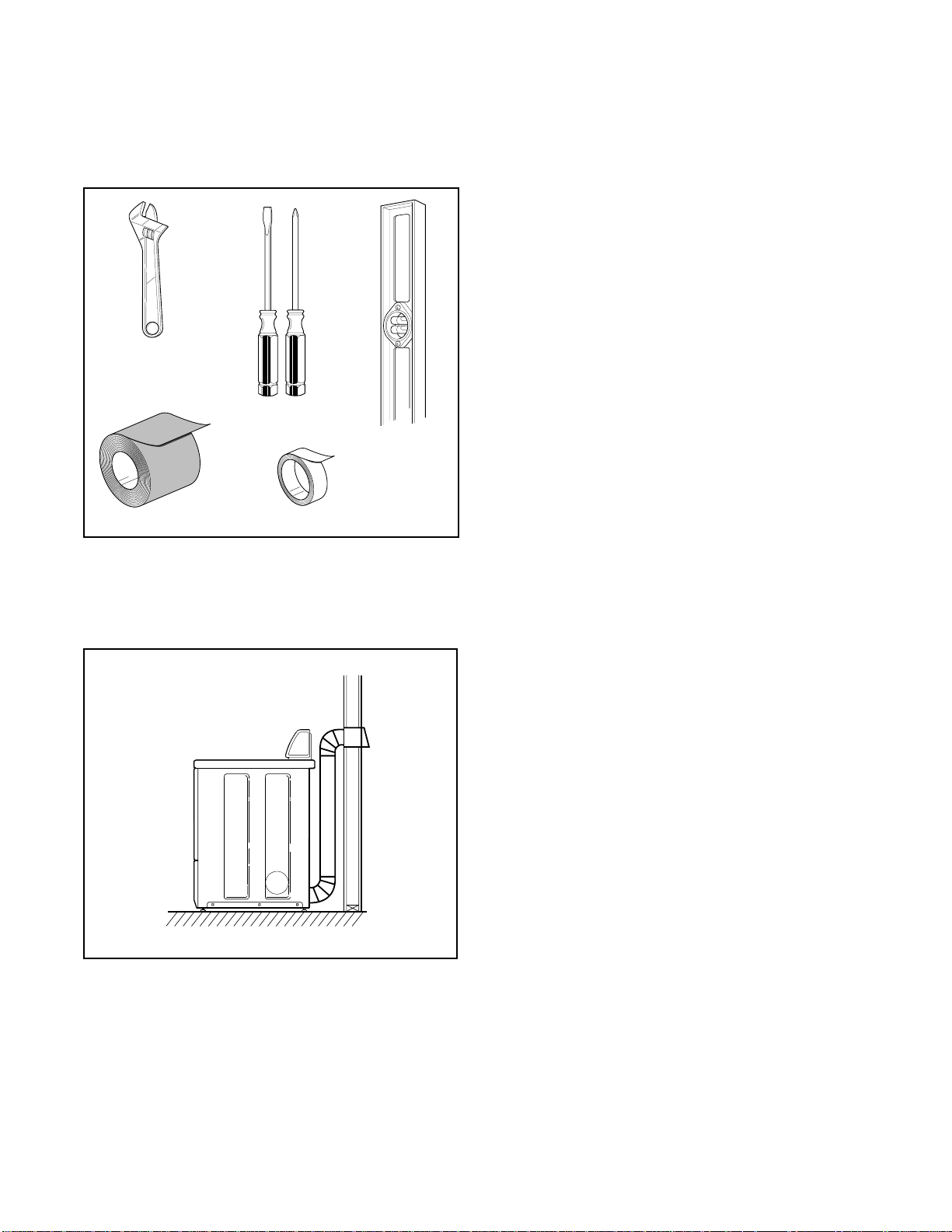
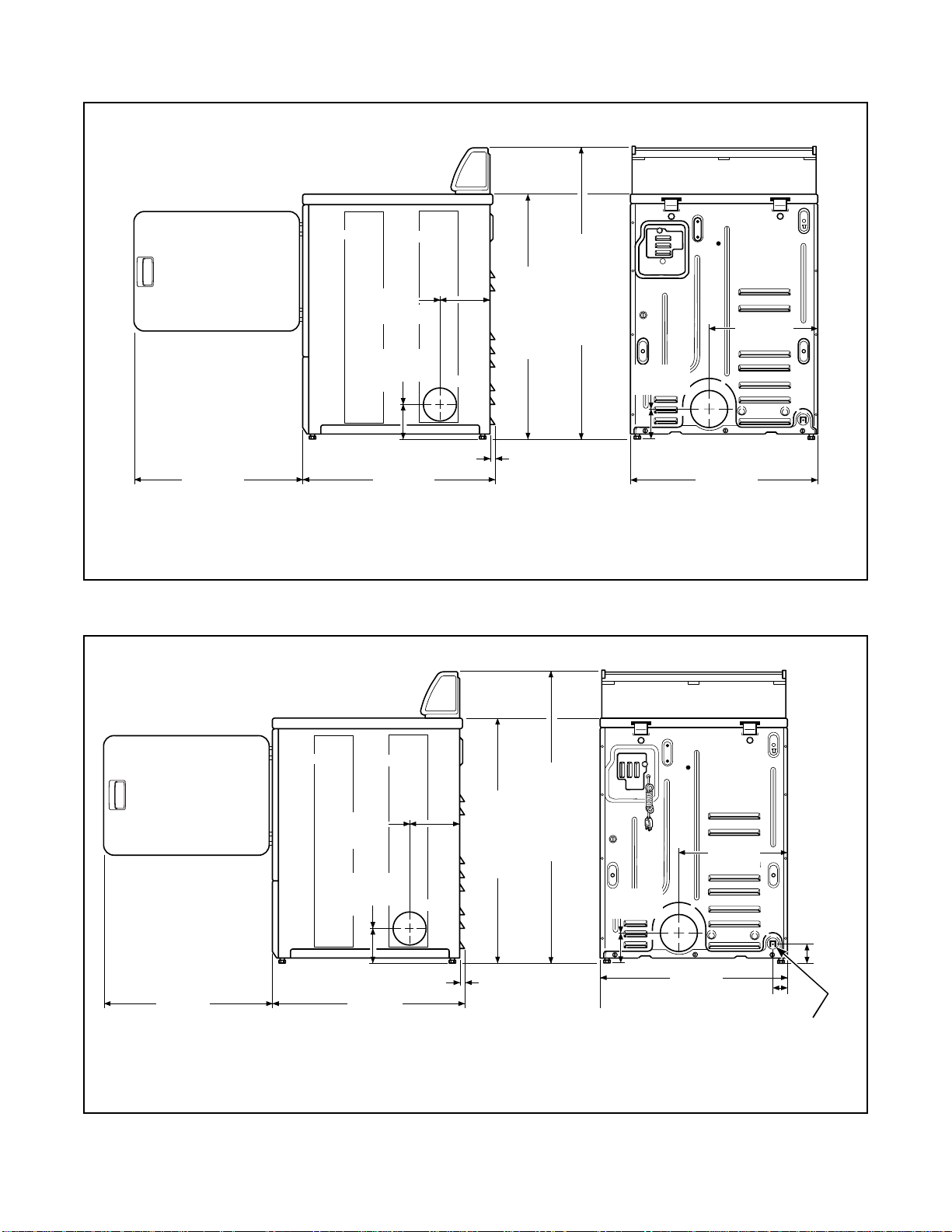
Before You Start . . .
D074IE1F
DUCT TAPE
TEFLON TAPE
WRENCH
LEVEL
SCREWDRIVERS
Tools
For most installat ions, the basic to ols you will need are:
Exhaust
Electrical
• ELECTRIC DRYER
Dryer needs a 2 wire plus earth, 250 Volt, 50 Hertz,
20 Amp, single phase electrical supply.
• GAS DRYER
Dryer needs a 2 wire plus earth,250 Volt, 50 Hertz,
10 Amp, single phase electrical supply.
NOTE: For more detailed information, refer to
Section on Electrical Requirements.
Gas
Dryer is equipped for Natural Gas with a 3/8" NPT gas
supply connection. For more detailed information,
refer to Sec tion on Gas Requirements.
Location
Place the dryer on a solid floor with an adequate air
supply . For mo re detail ed informat ion, refer to Section
on Location Requirements.
Use rigid metal duct and exhaust the dryer to the
outside by the shortest route possible.
D314IE0A
NOTE: For more detailed information, refer to
Section on Dryer Exhaust Requirements.
4 510955
Page 7
Installing the Dryer . . .
A clothes dryer produces combustible lint.
To reduce the risk of fire and combustion
gas accumulation the dryer MUST be
exhausted to the outdoors.
W116
WARNING
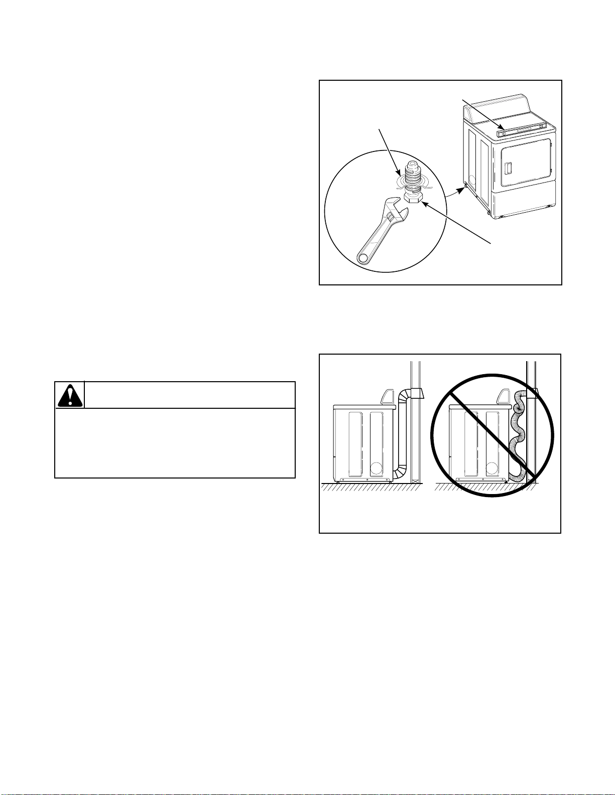
Step 1:
Position and Level
the Dryer
For further assistance refer to Section on Location
Requirements.
Install dryer before washer. This allows room for
attaching exhaust duct.
Place the dryer in position , and adj ust the l egs unt il the
dryer is level from side to side and front to back.
Step 2:
Connect Dryer Exhaust System
DRYER
BASE
D259I
LEVEL
LEVELING
LEG
D669IE1A
For further assis tance refer to Sections on Location
Requirements and Dryer Exhaust Requirements.
• DO NOT use plastic or thin foil flexible ducting.
• Locate dryer so exhaust duct is as short as possible.
• Be certain old ducts are cleaned before installing
your new dryer.
• Use 4" (10.2 cm) diameter rigid or flexible metal
duct.
• The male end of each section of duct must point
away from the dryer.
• Use as few elbows as possible.
• Use duct tape on all duct joints.
D314IE0C
DO
NOTE: Venting materials are not suppli ed with the
dryer (obtain locally).
DON'T
D315IE0C
• Ductwork that runs through unheated areas must be
insulated to help reduce condens ation and lint build -up
on pipe walls.
• Failure to exhaust dryer properly will void
warranty.
510955 5
Page 8
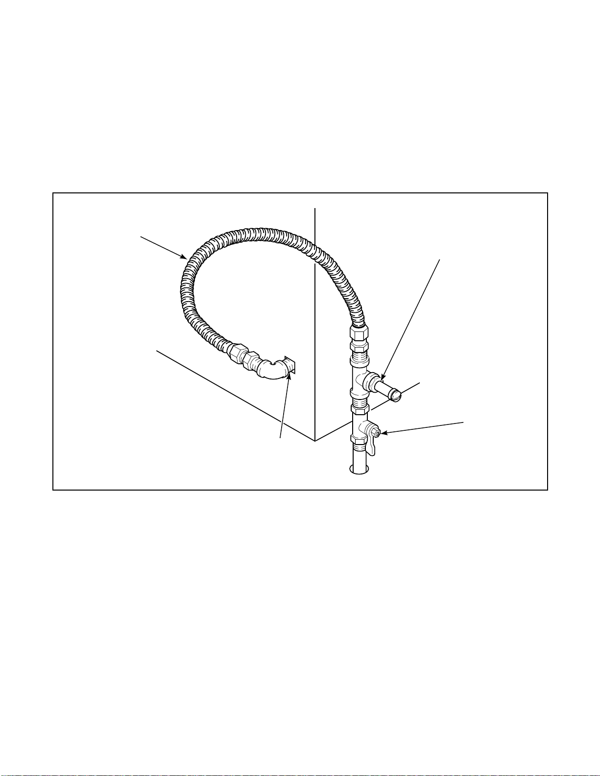
Step 3: (Gas Dryer ONLY)
Connect Gas Supply Pipe
For further assistance, refer to Section on Gas Requirements.
1. Make certain your dryer is equipped for use with
the type of gas in your laundry room. Dryer is
equipped at the factory for Natural Gas with a 3/
8" NPT gas connection.
2. Remove the shipping cap from the gas connection
at the rear of the dryer. Make sure you do not
damage the pipe threads when removing the cap.
NEW
STAINLESS
STEEL
FLEXIBLE
CONNECTOR
USE ONLY
IF ALLOWED
BY LOCAL
CODES
(Use
Design AGA
Certified
Connector)
3. Conne ct to gas sup ply pipe.
4. Tighten all connections securely. Turn on gas and
check all pipe connections (internal & external ) for
gas leaks with a non-corrosi ve leak detec tion fluid.
5. For L.P. ( propan e) g as c onnect ion , ref er to Sec tion
on Gas Requirements.
PRESSURE
TEST
POINT
3/8" NPT
GAS CONNECTION
SHUT-OFF
VALVE
D246IE3B
6 510955
Page 9
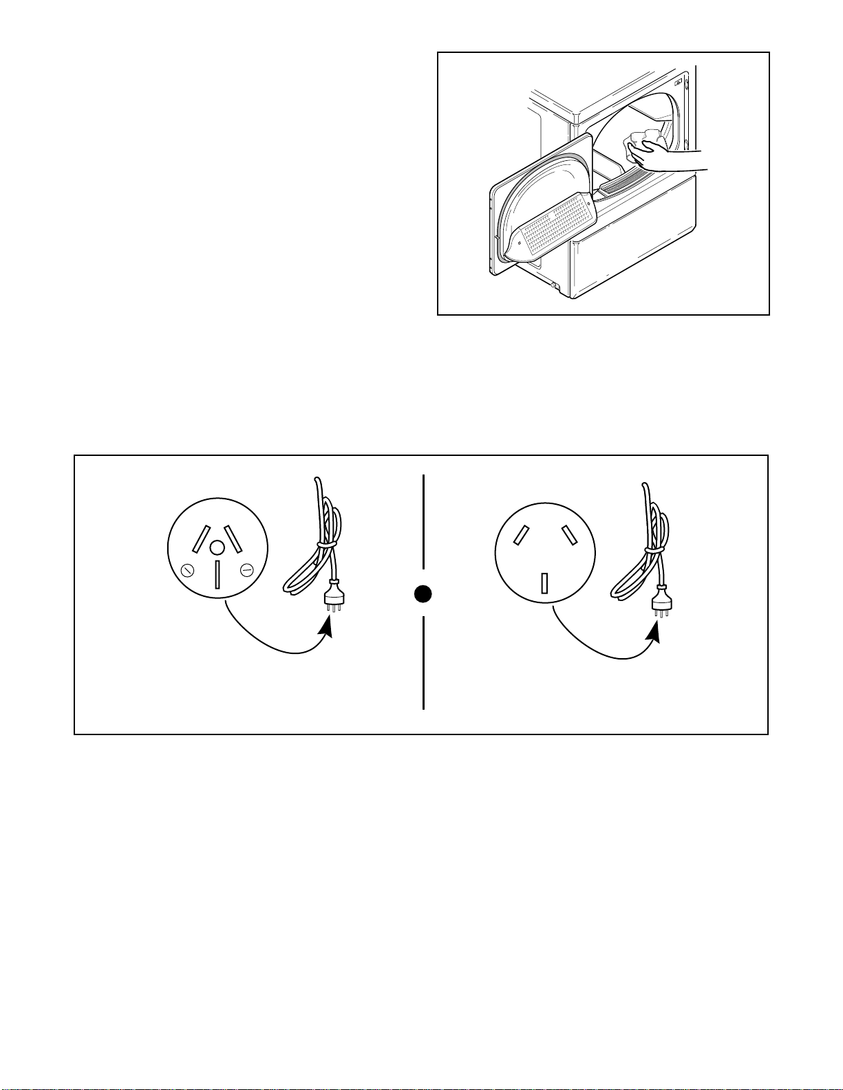
Step 4:
Wipe Out Inside Of Dryer
Before using dryer for the first time, use an all-purpose
cleaner, or a detergent and water solution, and a damp
cloth to remove shipping dust from inside dryer drum.
Step 5:
Plug in the Dryer
Refer to Section on Electrical Requirements, and
connect the dryer to an electrical power source.
D618I
20 A
250 V
D670I
ELECTRIC GAS
Step 6:
Check Installation
Refer to Installer Check on the back cover of this
manual and make sure that dryer is installed correctly.
250 V
10A
D671I
510955 7
Page 10

Heat Check . . .
(Electric Dryers)
Close the loading door and start the dryer in a heat
setting (refer to the Operating Instructions supplied
with the dryer). After the dryer has operated for three
Burner Flame . . .
(Gas Dryers)
IMPORTANT: This operation to be conducted by qualified personnel only.
T o view the burner flame, remove the lower front panel
of the dryer.
Close the loading door, start the dryer in a heat sett ing
(refer to the Operating Instructions supplied with the
dryer); the dryer will start, the ig niter will glo w red and
the main burner will ignite.
IMPORTANT: If ignitor is not lit, make sure gas i s
turned on.
IMPORTANT: If all air is not purged out of gas
line, gas igniter may go off before gas is ignited. If
this happens, after approximately one minute,
igniter will again attempt gas ignition. If ignition
does not occur after the fourth ignition attempt, the
control will lock out and red light wi ll flash (see
figure at right). If lockout occurs, open loading
door for one minute to reset control. When control
is properly reset, flashing will stop.
minutes, the exhaust air or exhaust pipe should be
warm.
c. After the air shutter is adjusted for p roper flame,
tighten the air shutter lockscrew securely.
d. Reinstall the lower front panel.
WARNING
T o reduce t he risk of serious injury or death,
the lower front panel must be in place
during normal operation.
W158
After the dryer has operated for approximately three
minutes, exhaust air or exhaust pip e should be warm.
WR
After the dryer has operated for approximately five
minutes, observe burner flame through lower front
DISCONNECT POWER BEFORE
SERVICINGGDGHDHJD DHJD DHD HD
HD HD HDGFJGFKGK GFJHGJ FHFH
F KJFJF KH GJHJF JDAPALS DK KF
DISCONNECT POWER
BEFORE SERVICING
DISCONNECT POWER
BEFORE SERVICING
DISCONNECT POWER
BEFORE SERVICING
DIAGNOSTIC INDICATOR
BEFORE SERVICING
DISCONNECT POWER
DISCONNECT POWER
BEFORE SERVICING
DISCONNECT POWER
DISCONNECT POWER
BEFORE SERVICING
BEFORE SERVICING
WARNING
WR
MODEL 50A72-203.
DISCONNECT POWER BEFORE
SERVICING SERVICEING OK
IMPORTANT
WHITE - ROGERS DIV.
EMERSON ELECTRIC CO.
panel. Adjust the air shutter to obtain a soft, uniform
blue flame. (A lazy, yellow-t ipped flame indica tes lack
of air. A harsh, roaring, very blue flame indicates too
much air.) Adjust the air s hutter as foll ows:
a. Loosen the air shutter lockscrew.
b. Turn the air shutter to the left to get a luminous
yellow-ti pped flame, then turn it back slo wly to the
RED
LIGHT
D251IE1A
right to obtain a steady, soft blue flame.
8 510955
Page 11

Reversing Door Procedure . . .
1
Remove four hinge
attaching screws.
D268PE1A
Pull bottom of
door liner out,
then pull down,
removing door
liner from door
panel.
3
B
A
D276PE1B
5
Remove door strike
from door liner
and reinstall on
opposite side.
D270PE1B
7
Reinstall nine screws
removed in Step 2.
The door on this dryer is completely reversible. To reverse door proceed as follows:
2
Remove all nine screws.
D675I
4
Rotate door panel
180 degrees
as shown.
6
Insert liner under
flange on bottom of
door, then push
top of door
liner into place.
D272PE1A
D273PE1C
B
A
D269PE1C
510955 9
8
Using a screwdriver,
remove two door
plugs, and reinstall on
opposite side of door
opening.
D620I
9
Reinstall four hinge
attaching screws
removed in Ste p 1.
D623I
Page 12

Manufactured (Mobile) Home
To reduce the risk of fire and combustion
gas accumulation, the dryer MUST BE
EXHAUSTED TO THE OUTDOORS. Refer to
Section on Dryer Exhaust Requirements.
W047
WARNING
Installation . . .
IMPORTANT: Installation must conform to
the Manufactured Home Construction and
Safety Standards, Title 24 CFR, Part 32-80 or
Standard CAN/CSA-Z240 MH.
The dryer can be installed in a manufactured (mobile)
home by following these instructions:
1. IMPORTANT: Gas dryers MUST be
permanently attached to the fl oor at the time of
installation. Order No. 526P3 Dryer Installat ion
Kit for a manufactured (mobile) home
installation. Follow the instructions supplied
with the kit.
2. Venting—Dryer MUST be exhausted to the
outdoors.
• The dryer can be exhausted to the outdoors through
the back, left, right or bottom panel. Gas dryers
cannot be exhausted out the left side because of the
burner housing.
• The dryer exhaust duct must be secured to the
mobile home structure.
• Exhaust duct must not be connected to any other
duct, vent or chimney.
• Dryer exhaust duct MUST NOT terminate under the
mobile home.
• For proper operation, it is important that the dryer
has an ample amount of outside make-up air. The
free area of any opening for the introduction of
outside air must be at least 25 in
• When exhausti ng the dryer to the outdoo rs, the dr yer
can be installed with “0” inch clearance at the sides
and rear. Clearance of the duct from combustible
construction must be a minimum of 2 inches (5.08
cm).
• Venting materials are not supplied with the dryer
(obtain locally).
2
(163 cm2).
W ARNING
To reduce the risk of fire, the exhaust duct
and weather hood MUST be fabricated of a
material that will not support combustion.
Rigid or flexible metal pipe is recommended
for a clothes dryer.
W048
• Exhaust ducts MUST NOT be connected with sheet
metal screws or fasteners which extend into the duct.
10 510955
Page 13

dF4a4"dF¤aFh Fm
20 A
250 V
LEAD-IN
EARTH
SCREW
CORD
EARTH
D672IE1A
LEAD-IN
CORD PLUG
(Electric Dryers)
NOTE: The wiring diagram is located inside the
control hood.
IMPORTANT: The electrical i nstallation in the site
shall comply with the latest edition of Australian
Electrical Standards , AS30 00, SAA wirin g rules ,
and such local regulations that might apply.
This dryer is designed to be operated on a two wire,
plus earth, 240 Volt, 50 Hertz, single phase circuit,
fused at 20 amperes.
Insert the dryer’s lead-in cord plug into an earthing
three-slot-plus earth, wall receptacle on a separate
circuit. DO NOT OPERATE OTHER APPLIANCES
ON THE SAME CIRCUIT WHEN THE DRYER IS
OPERATING. DO NOT USE AN EXTENSION
CORD.
If the supply cord is damaged, it must be replac ed by a
special cord or assembly available from the
manufactu rer o r its service agent.
510955
11
Page 14

Electrical Requirements . . .
10A
250 V
LEAD-IN
EARTH
SCREW
CORD
EARTH
D676IE1A
LEAD-IN
CORD PLUG
(Gas Dryers)
NOTE: The wiring diagram is located inside the
control hood.
IMPORTANT: The electrical inst allation in th e site
shall comply with the latest edition of Australian
Electrical Standards, AS3000, SAA wiring rules,
and such local regulations that might apply.
This dryer is designed to be operated on a two wire,
plus earth, 240 Volt, 50 Hertz, single phase circuit,
fused at 10 amperes.
Insert the dryer’s lead-in cord pl ug into an ear t hing
three-slot wall receptacle on a separate circuit. DO
NOT OPERATE OTHER APPLIANCES ON THE
SAME CIRCUIT WHEN THE DRYER IS
OPERATING. DO NOT USE AN EXTENSION
CORD.
Earthing Instructions
The dryer must be eart hed. I n the e v ent of malfu nctio n
or breakdown, earthing will reduce the risk of electric
shock by provi ding a path of least resist ance for electric
current. The dryer is equipped with a cord having an
equipment-earthing conductor and a 3-prong earthing
plug. The plug must be plugged into an appropriate
outlet that is properly installed and earthed in
accordance with local codes and ordinances.
WARNING
Improper connection of the equipmentearthing conductor can result in a risk of
electric shock. Check with a qualified
electrician or serviceman if you a re in do ubt
as to whether the dryer is properly earthed.
W159
Do not modify the plug provide d with the drye r—if it
will not fit the outlet, have a proper outlet installed by
a qualified electrician.
If your home’s electrical supply does not meet the
above spec ificati ons and/or y ou are not sure your home
has an effective earth, have a qualified electrician or
your local electrical utility company check it and
correct any problems.
If the supply cor d is da maged, it must be repla ced b y a
special cord or assembly available from the
manufacturer or its service agent.
12 510955
Page 15

Gas Service . . .
(Gas Dryers)
NOTE: The gas service to a gas dryer must conform
with the local codes and ordinances and AG601,
Installation Code for Gas Burning Applia nces. In
the absence of local codes and ordinances,
applicable National codes should be followed.
Connection of Gas Supply Pipe
1. Install the dryer with sufficient clearance for
adequate air circulation, and for the ease of the
dryer installation, servicing and operation. For
maximum drying performance, we recommend
you allow more clearance than the clearances that
are listed throughout this manual.
2. Remove the shipping cap from the gas connection
at the rear of the dryer. Make sure you do not
damage the pipe threads when removing the cap.
3. Make certain your dryer is equipped for use with
the type of gas in your laundry room.
3
NOTE: Natural gas, 1,000 Btu/ft
service must be supplied at 6.5 ± 1.5 inch (1.6 ± .4
kPa) water column pressure. Do not connect the
dryer to L.P. (propane) gas service without
converting the gas valve. A No. 401P3 L.P.
(propane) Gas Conversio n Kit must be i nst al led by
the Manufacturer’s Authorized Dealers,
Distributors, or local service personnel.
NOTE: L.P. (propane) gas, 2,500 Btu/ft
3
), service must be supplied at 10 ± 1.5 inch (2. 5 ±
m
.4 kPa) water column pressure and a vent to the
outdoors must be provided.
4. If local codes allow the use of flexible ga s tubing,
connect the 3/8 inch NPT (National Pipe Th read)
gas connec tion at the rear of the dryer to the
laundry room’s gas line wit h ne w fl exib le stai nless
steel tubing (usi ng d esi gn certified Australian Gas
Association connector only).
(37.3 MJ/m3),
3
(93.1 MJ/
WARNING
To reduce the risk of gas leaks, fire or
explosion:
• The dryer must be connected to the type of
gas as shown on nameplate located in the
door recess.
• Use a new flexible stainless steel
connector.
• Use pipe joint compound insoluble in LP
(propane) Gas, or Teflon tape, on all pipe
threads.
• Purge air and sediment from gas supply
line before connecting it to the dryer.
Before tightening the connection, purge
remaining air from gas line to dryer until
odor of gas is detected. This step is
required to prevent gas valve
contamination.
• Do not use an open flame to check for gas
leaks. Use a non-corrosive leak detection
fluid.
NEW
STAINLESS
STEEL
FLEXIBLE
CONNECTOR
USE ONLY
IF ALLOWED
BY LOCAL
CODES
(Use
Design AGA
Certified
Connector)
PRESSURE
3/8" NPT
GAS CONNECTION
W114R1
TEST
POINT
SHUT-OFF
VALVE
D246IE1C
IMPORTANT: Use local codes of practice for gas
installation.
This dryer is equipped with jet for Natural gas.
Gas Consumption Natural 21.9 MJ
L.P. (propane) 21.9 MJ
Gas Pressure Natural 0.88 kPa
L.P. (propane) 2.75 kPa
510955 13
Page 16

NOTE: When connecting gas supply li ne, a pressure
test point must be installed downstream from the
shutoff valve for checking inlet gas pressure.
5. The gas line to yo ur laundr y room sho uld be made
of black iron pipe. A 3/8 inch (9.5 mm) pipe with
an inside diameter of .46” (11.7 mm) will be
adequate if len gth of su pply l ine is not ov er 20 feet
(6 m). If length exceeds this, use 1/2” (12.7 mm)
pipe. If copper semi-rigid tu bing is used it must be
internally tinned or equivalently treated to resist
sulfur corrosion.
NOTE: The dryer and its appliance main gas valve
must be disconnected from the gas supply piping
system during any pres sure testing of tha t system at
test pressures in excess of 1/2 psig (3.45 kPa).
Natural Gas Altitude Adjustments
The dryer must be isolated from the gas supply piping
system by closing the equipment shutoff valve during
any pressure te sting of the ga s sup ply pipi ng syst em at
test pressure equal to or less than 1/2 psig (3.45 kPa).
6. Check all pipe connections (internal and external)
for gas leaks with a soapy solution. Gas
connections should be checked annually for
leakage.
7. Be sure the shut off valve in your dryer is OPEN.
Your dryer is shipped with the valve open.
8. The dryer gas v alve is equipped with a pressure test
point for checking manifold pressure.
For proper ope rat ion a t alt itude s abo v e 3,000 fe et (915
m) the natural gas valve spud orifice size must be
reduced to en sure complete combustion. Se e table
below.
Altitude Orifice Size
ft m # Inches mm
3000 915 43 0.0890 2.26 503778
6000 1830 44 0.0860 2.18 58719
8000 2440 45 0.0820 2.08 503779
9000 2740 46 0.0810 2.06 503780
10000 3050 47 0.0785 1.99 503781
Part
Number
14 510955
Page 17

Location Requirements . . .
Select a location with a solid floor.
No other fuel burning appliance should be installed in
the same closet with the dryer.
The dryer must not be installed or stored in an area
where it will be exposed to water and/or weather.
Leveling legs can be adjusted from inside the dryer
CLOSET
DOOR
B
with a 1/4" driver. All four legs must rest firmly on the
floor so the weight of the dryer is evenly distributed.
The dryer must not rock.
The dryer needs sufficient clearance and an adequate
air supply for pr oper operat ion a nd v enti lati on, an d for
easier instal lation and servicing. ( Minimum clea rances
are shown below.)
F
CENTERED
AIR
D
A
E
**42"
OPENINGS (G)
(2 Openings
Minimum)
A
FRONT VIEW
(w/o Closet Door)
AREA DESCRIPTION FREE STANDING / ALCOVE
A Dryer sides and rear clearance 0" (0 cm) 0" (0 cm)
B Dryer top clearance 12" (30.5 cm) 12" (30.5 cm)
C Dryer front clearance Not Applicable 2" (5.1 cm)
D Exhaust duct clearance to
E Weather hood to ground clearance 12" (30.5 cm) 12" (30.5 cm)
F Distance from floor or ceiling to
G* Area of centered air openings in
AC
SIDE VIEW
INSTALLATION
(See Illustration)
2" (5.1 cm) 2" (5.1 cm)
combustible material
Not Applicable 3" (7.6 cm)
hole edge
Not Applicable 40 sq. in./open (260 sq. cm)
closet door
OUTER
WALL OF
ENCLOSURE
FRONT VIEW
(Closet Door)
CLOSET INSTALLATION
(See Illustration)
*Louvered door with equivalent air openings is acceptable. (Minimum clearances are shown.)
F
D317IE3A
**NOT E: For new inst allations, locate top of wall vent 42 inches above floor to make venting easier to
connect.
510955 15
Page 18

Dryer Exhaust Requirements . . .
A clothes dryer produces combustible lint.
To reduce the risk of fire and combustion
gas accumulation the dryer MUST be
exhausted to the outdoors.
W116
This gas appliance contains or produces a
chemical or chemicals which can cause
death or serious illness and which are
known to the State of California to cause
cancer , birth defects, or other reproductive
harm. T o r educe the risk fr om substances in
the fuel or from fuel combustion, make sure
this appliance is installed, operated, and
maintained according to the instructions in
this manual.
W115
To reduce the risk of fire and the
accumulation of combustion gases, DO NOT
exhaust dryer air into a window well, gas
vent, chimney or enclosed, unventilated
area, such as an attic, wall, ceiling, crawl
space under a building or concealed space
of a building.
W045
To reduce the risk of fire, DO NOT use
plastic pipe or flexible plastic pipe to
exhaust the dryer.
W041
WARNING
DO
D314IE0C
DON'T
D315IE0C
Exhaust System Materials
Exhaust duct must be four i nches (10.2 cm) in diamete r
having no obstructions. Rigid metal duct is
recommended. Non-combustible semi-rigid flexible
metal duct is acceptable. Do not use plastic pipe or
flexible plastic pipe, because it contributes to poor
drying performance a nd collects li nt, which ca n lead to
a fire hazard.
DO NOT use sheet met al screws on exhaust pi pe joints
or other fastening means which extend into the duct
that could catch lint and reduce the efficiency of the
exhaust system. Secure all joints with duct tape.
Make-Up Air Requirements
For proper operation it is important t hat you locate the
dryer in an area that has an ample amount of make-up
air to replace the amount exhausted by the dryer.
Energy efficient homes with low air infiltration rates
should be equipped with an air exchanger that can
accommodate on demand make-up air needs in the
home. These devices can be obtained through your
building contractor or building material suppliers.
Never install flexible duct in concealed spaces, such as
a wall or ceiling.
16 510955
Page 19

Exhaust System
IMPORTANT: Keep exhaust duct as short as
possible.
Exhausting the dryer through sides or bottom can be
accomplished by installing a DK1 Sales Accessory
(Directional Exhaust Kit 528P3) available as optional
equipment at extra cost.
NOTE: Be certain old ducts are cleaned before
installing your new dryer.
For best dr ying results, recomme nded maximum length
of exhaust system is shown in table below.
To prevent backdraft when dryer is not in operation,
outer end of exhaust pipe must have a weather hood
with hinged dampers (obtain locally).
NOTE: Weather hood should be installed at least
12 inches (30.5 cm) above the ground. Larger
clearances may be necessary for inst allations where
heavy snowfall can occur.
Exhaust Direction
The dryer can be e xhausted to the o utdoors thr ough the
back, left, right o r bottom of the drye r . EXCEPTION:
Gas dryers cannot be vented out the left side
because of the burner housing.
Dryer is shipped from factory ready for rear exhaust;
no kits required.
Number of
90° Elbows
Recommended Use only for short run installations
IMPORTANT: Do not block the airflow at the
bottom of the dryer’s front panel with laundry,
rugs, etc. Blockage will decrease airflow through
the dryer, thus reducing the efficiency of the dryer.
D328IE0A
528P3 Directional Exhaust Kit
Weather Hood Type
4"
(10.2 cm)
4"
(10.2 cm)
D673IE1A
2-1/2"
(6.35 cm)
D011IE2E
Maximum length of 4" (10.2 cm) diameter rigid metal duct.
0 65 feet (19.8 m) 55 feet (16.8 m)
1 55 feet (16.8 m) 47 feet (14.3 m)
2 47 feet (14.3 m) 41 feet (12.5 m)
3 36 feet (11.0 m) 30 feet (9.1 m)
4 28 feet (8.5 m) 22 feet (6.7 m)
Maximum length of 4" (10.2 cm) diameter flexible metal duct.
0 45 feet (13.7 m) 35 feet (10.7 m)
1 35 feet (10.7 m) 27 feet (8.2 m)
2 30 feet (9.1 m) 21 feet (6.4 m)
3 25 feet (7.6 m) 17 feet (5.2 m)
4 20 feet (6.1 m) 15 feet (4.5 m)
NOTE: Deduct 6 feet (1.8 m) for each additional elbow.
510955 17
Page 20

Exhaust Sys tem Maintenance
To reduce the risk of electric shock,
disconnect the electrical servic e to the dryer
before cleaning.
W043
WARNING
521P3 Flexible Metal Vent Kit
Dryer Airflow
The dryer interior and the complete exhaust system
should be inspected af ter one year of use and cleaned if
necessary. Inspect and clean exhaust duct every one to
two years as required thereafter. The weather hood
should be checke d frequently to ma ke sure the damper s
move freely, dampers are not pushed in and that
nothing has been set against them. This maintenance
work should be done by a qualified service person.
Exhausting the drye r i n hard-to-reach locations can be
accomplished by installing the 521P3 Flexible Metal
Vent Kit, available a s opti onal e quipment at e xt ra c ost.
The kit comes in two halves that can be separately
attached to the dr yer and wall ou tlet. Once attached, the
dryer can be sli d b ack into position and the two halves
can be connected from the front.
Effi cient dr yer operat ion requi res prope r dryer ai rflo w.
Proper dryer ai rflow ca n be ev aluate d by measu ring the
static pressure.
Static pressure i n the dryer’s exhaust duct sho uld be no
greater than that sh own in the ch art below. (Check with
dryer running and no load.)
NOTE: This can be measured with a manometer
placed on the exhaust duct approximately two feet
(61 cm) from the dryer, see illustration below.
MAXIMUM STATIC
PRESSURE IN
WATER COLUMN
.4 INCHES (0.1 kPa)
MANOMETER
D615I
EXHAUST
DUCT
D012IE0A
Reduced Clearance Elbow
Installing the dryer in shallow closets can be
accomplished by using an Elbow, Part No. 62688,
which is one inch narrower than a standard venting
elbow.
D319IE0A
18 510955
Page 21

User-Maintenance Instructions . . .
Lubrication
All moving parts are sealed in a permanent supply of
lubricant or are equipped with oilless bearings.
Additional lubrication will not be necessary.
Care of Your Dryer
Label all wires prior to disconnection when
servicing controls. Wiring errors can cause
improper and dangerous operation.
CAUTION
W049
Clean the lint filter after drying each load. The lint filter
may be washed if needed. Annually remove lint filter
and screw to vacuum the duct under it.
Ordinarily, the dryer cylinder will need no care.
Wipe the dryer cabinet as needed. If detergent, bleach
or other washing products have been spilled on the
dryer, wipe immediately. Some products will cause
permanent damage if spilled on the cabinet.
Do not allo w sharp or rou gh ob jects to le an ag ai nst th e
dryer. The finish could be damaged.
Use only a damp or sud sy cloth for clea ning the control
panel. Some spray prewash products may harm the
finish on the control panel.
NOTE: The wiring diagram is located inside the
control panel.
Exhaust System
The exhaust duct sh ould be in spe cted af ter one year of
use and cleaned if necessary. Inspect and clean exhaust
duct every one to two years as required thereafter.
The weather hood should be checked frequently to
make sure the dampers move freely, dampers are not
pushed in a nd that nothing has been set against them.
Keep dryer area clear and free from combustible
materials, gasoline and other flammable vapors and
liquids.
Do not obstruct the flo w of combusti on and ventil ation
air .
NOTE: Verify proper operation after servicing.
510955 19
Page 22

Wiring Diagram
(Electric Dryer)
20 510955
Page 23

Wiring Diagram
(Gas Dryer)
510955 21
Page 24

Information for Handy Reference . . .
Date Purchased
Model Number Serial Number
Store Name
Store Address Phone Number
Service Agency
Service Agency Address Phone Number
NOTE: Record the above information and keep your sales slip . Model and serial numbers are locate d
on the nameplate.
Customer Care Centre and
Information Freecall:
1-800-072-144
22 510955
Page 25

Page 26

Page 27

Page 28

Installer Check . . .
Fast Track for Installing the Dryer
(Refer to the manual for more detailed information)
➊
• Position and Level
the Dryer.
LEVEL
CHECK
➋
• Connect Dryer Exhaust System.
➍
➎
CHECK
•Plug In
the
Dryer.
D618IE0A
20 A
250 V
D670IE0A
ELECTRIC
•Wipe Out
Inside of
Dryer.
10A
250 V
D671IE0A
GAS
CHECK
➌
GAS ONLY
• Connect Gas
Supply Pipe.
• Check for Gas
Leaks.
CHECK
CHECK
510955
 Loading...