

Page 1
IICCKK6666XX --
600 mm Induction Cooktop
IICCKK8800XX --
800 mm Induction Cooktop
IICCKK9900XX --
900 mm Induction Cooktop
Instructions for fitting and using your
induction
and
Warranty Details
The best you can own
Copie de 99636771_EN_A.qxd 20/05/05 09:34 Page 1
Page 2
2
As part of our commitment to constantly improving our products, we reserve the right to make
changes to them based on technological advances to their technical, functional and/or aesthetic properties.
Attention
BBeeffoorree iinnssttaalllliinngg aanndd uussiinngg yyoouurr aapppplliiaannccee,, pplleeaassee ccaarreeffuullllyy rreeaadd tthhiiss GGuuiiddee ttoo
IInnssttaallllaattiioonn aanndd UUssee,, wwhhiicchh wwiillll aallllooww yyoouu ttoo qquuiicckkllyy ffaammiilliiaarriissee yyoouurrsseellff wwiitthh iittss ooppeerraattiioonn..
Young children should be supervised to ensure that they do not play with the appliance.
The appliance is not intended for use by young children or infirm person without supervision.
If the supply cord is damaged, it must be replaced by the manufacturer or its service agent or a similarly qualified person in order to avoid hazard.
Congratulations on the purchase of your new appliance.
This appliance has been
designed and manufactured to give you years
of reliable performance.
For best results,carefully read the instructions on how to
install your new appliance. Correct installation will avoid
delays and unnecessary service calls.
Once installation is complete, read this booklet
carefully and get to know the controls and the
features of your new appliance.
We reserve the right to alter the specifications
with no influence on the operation of the
appliance.This instruction manual cannot be
reason for a claim.
Copie de 99636771_EN_A.qxd 20/05/05 09:34 Page 2
Page 3

3
TABLE OF CONTENTS
• Safety Guidelines
____________________________________________________
04
•
Description of Your Appliance
_________________________________________
05
• Environmental Protection
_____________________________________________
05
1 / INSTALLING YOUR APPLIANCE
• Proper positioning
___________________________________________________
06
• Building in
__________________________________________________________
06
• Hook-up
___________________________________________________________
07
2 / USING YOUR APPLIANCE
• Description of the top
_________________________________________________
10
• Cookware for induction
_______________________________________________
11
• Which cooking zone should you use based on your cookware?
_____________
11
• Description of control panel
___________________________________________
12
• Powering on
________________________________________________________
12
• Adjusting the power
_________________________________________________
12
• Setting the timers
____________________________________________________
12
• Using the "child safety device"
_________________________________________
12
• Safeties during operation
_____________________________________________
13
3 / DAILY CARE OF YOUR APPLIANCE
• Protecting your appliance
_____________________________________________
14
• Maintaining your appliance
____________________________________________
14
4 / SPECIAL MESSAGES, DIFFICULTIES
• During initial use
____________________________________________________
15
•
When powering on
___________________________________________________
15
• During operation
____________________________________________________
15
5 / COOKING CHART
• Cooking chart for food types
__________________________________________
16
Copie de 99636771_EN_A.qxd 20/05/05 09:34 Page 3
Page 4

4
SAFETY GUIDELINES
We have designed this cooking hob for use by
private persons in their homes.
These cooking hobs are meant to be used
exclusively for cooking beverages and foodstuffs and do not contain any asbestos-based
materials.
••
Residual heat
A cooking zone can remain hot for several
minutes after use.
An
""HH""
is displayed during this period.
Avoid touching the hot areas during this time.
••
Child safety device
Your hob is equipped with a child safety device that locks its operation after use or during
cooking (See "Using the Child Safety Device"
section).
Do not forget to unlock it before using the
hob again.
••
For users of pacemakers and acti-
ve implants
The functioning of the hob conforms to current electromagnetic interference standards
and thus is in total compliance with legal
requirements (89/336/CEE directives).
In order to avoid interference between your
cooking hob and a pacemaker, your pacemaker must be designed and programmed in
compliance with the regulations that apply to
it.
Consequently, we can only guarantee that our
own product is compliant.
With regard to the compliance of the pacemaker or any potential incompatibility, you
can obtain information from the manufacturer
or your attending physician.
Electrical Danger
Ensure that the power cables of any
electrical appliances plugged in close to
the hob are not in contact with the cooking
zones.
If a crack appears in the glass worktop,
immediately disconnect your appliance to
avoid the risk of electric shock.
To do this, remove the fuses or use the circuit breaker.
Do not use your hob until you have replaced the glass worktop.
••
Copie de 99636771_EN_A.qxd 20/05/05 09:34 Page 4
Page 5
5
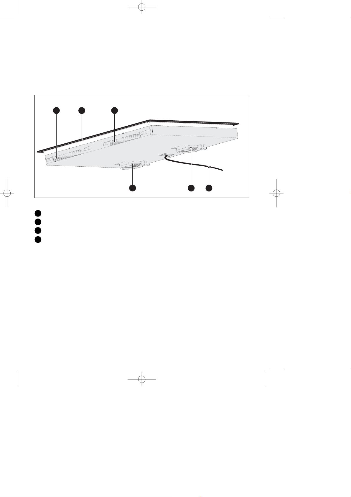
DESCRIPTION OF YOUR APPLIANCE
Air intake
Air outlet
Vitroceramic glass
Power cord
A
B
C
••
••
ENVIRONMENTAL PROTECTION
The packing materials can be recycled.
Dispose of them in containers provided for this purpose based on their individual recycling symbols.
Used appliances should be disposed of in compliance with the regulations in effect in your place
of residence.
D
Copie de 99636771_EN_A.qxd 20/05/05 09:34 Page 5
B
C
B
A
A
D
Page 6
6
11
/ INSTALLING YOUR APPLIANCE
••
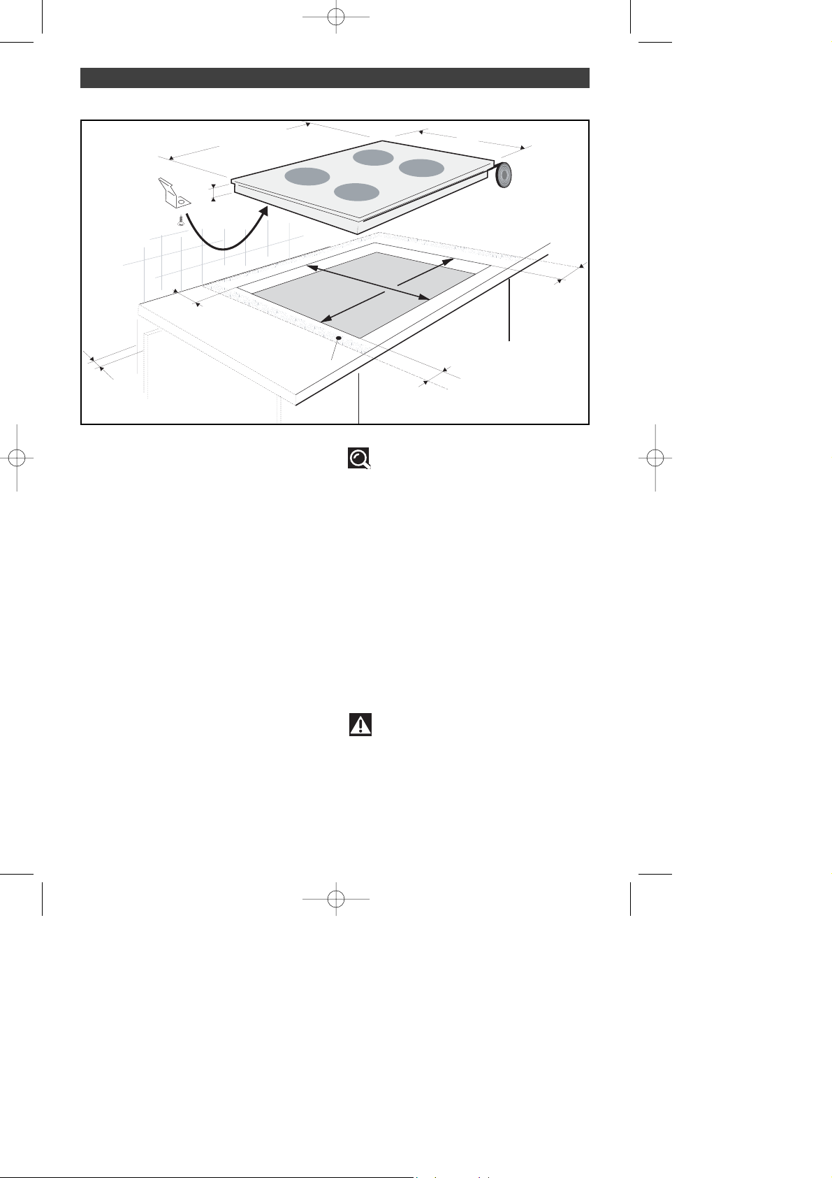
PROPER POSITIONING
Your appliance should be positioned so that
the plug-in unit is accessible.
The distance between the edge of your
appliance and the side and rear walls (or partitions) must be at least four centimetres (area
A).
Your appliance can be easily integrated above
a cabinet, an oven or a build-in-ready household appliance. You must simply ensure that
the air intakes and air outlets are clear (See
"Description of Your Appliance" section).
BUILD-IN
Follow the diagram above.
Glue the foam seal underneath your appliance
by following the outline of the worktop upon
which your appliance will rest. This will allow
you to achieve an airtight seal with the worktop.
Attach the clips to the hob.
ventilation
space
Tip
If your oven is located below your
hob, the hob's thermal safety measures forbid the simultaneous use of the hob and the
pyrolysis program of your oven.
Your hob is equipped with an anti-overheating safety device.
This safety can be activated, for example,
when the hob is installed over an oven that
is not sufficiently insulated. If this occurs, a
series of small lines appear in the control
panel. In this case, we recommend that you
increase the ventilation of your hob by creating an opening in the side of your cabinet
(8 cm x 5 cm) and/or that you install the
oven insulation kit (reference 75X1652) that
is available from the Post-Sales Service
Department.
Warning
You must ensure that the air intakes
located under your cooking appliance
remain clear at all times.
For all types of installation, your induction
hob needs proper ventilation.
5522
••
6600//7799//9944
66..44
4499
5566//7755//9900
Copie de 99636771_EN_A.qxd 20/05/05 09:34 Page 6
4 cm
4 cm
A
4 cm
4 cm
Page 7
7
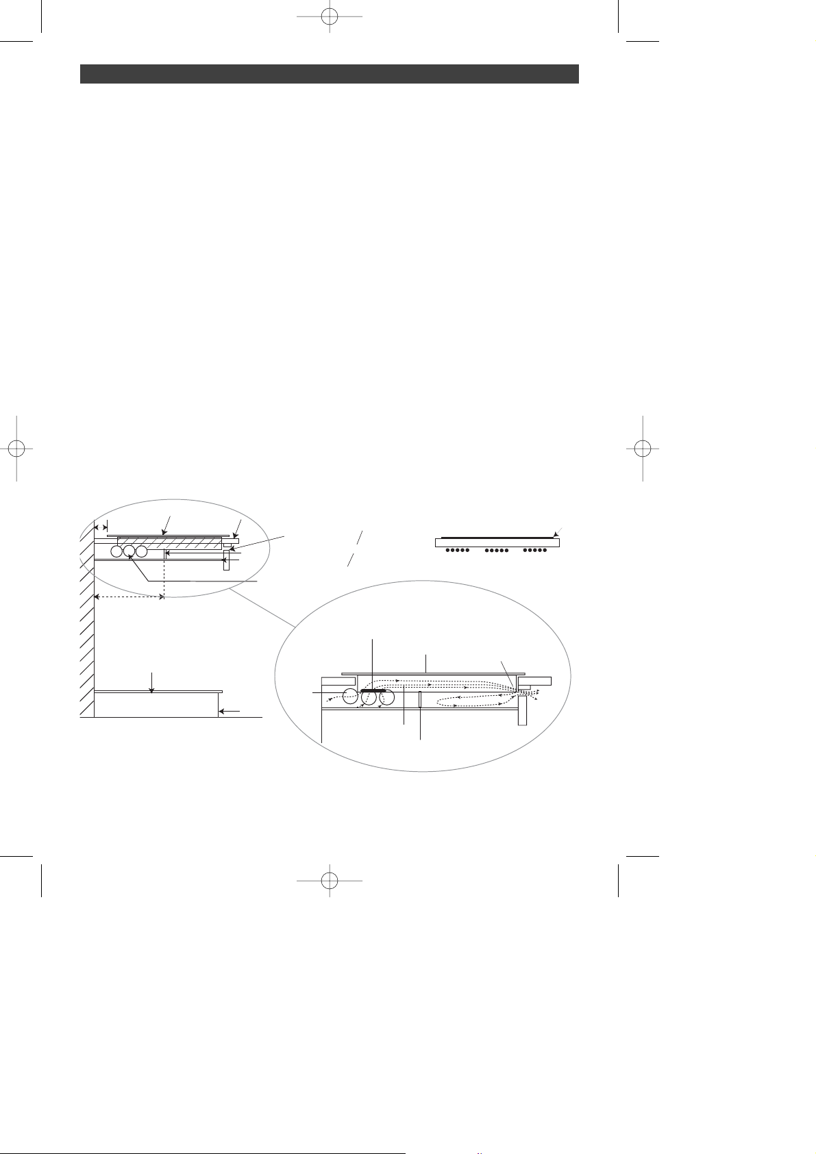
INSTALLATION/VENTILATION
REQUIREMENTS
When installing an induction hob above an
underbench oven, cupboard or drawer unit,
the following ventilation requirements must
be observed:
• Heat Shield (heat resistent material, eg.
melamine timber veneer) is to be positioned
at least 50mm below hob.
• Cooktop must be isolated from underbench area. Heat Shield edges to be sealed
to surrounding surfaces
• A Vertical Division (heat resistent material,
eg. melamine timber veneer) is to be positioned between the Heat Shield and the underside of the hob approximately 300mm from
back of cupboard. Length of Vertical Division
needs to be equal to
11
/ INSTALLING YOUR APPLIANCE
••
width of Heat Shield. Vertical Division must .t
tightly and act as a barrier to air .owing back
towards the cooling fan in hob (as per diagram).
• Ventilation holes must be drilled into side
of adjoining cupboards to allow fresh air
supply to cooktop.
•When installing into a granite worktop, drill
holes below worktop (as per diagram).
Insulation kit as shown in owners manual is
not required when installation is carried out
according to these speci.cations (this is not
supplied by Kleenmaid).
WWAARRNNIINNGG:: TThhee iinndduuccttiioonn ccooookkttoopp ccaannnnoott bbee
iinnssttaalllleedd aabboovvee aa ffrriiddggee,, ddiisshhwwaasshheerr oorr wwaass--
hhiinngg mmaacchhiinnee..
IInnccoorrrreecctt iinnssttaallllaattiioonn oorr ffaaiilluurree ttoo ffoollllooww
iinnssttrruuccttiioonnss mmaayy rreessuulltt iinn pprreemmaattuurree ffaaiilluurree
ooff ccooookkttoopp aanndd wwiillll vvooiidd wwaarrrraannttyy..
Copie de 99636771_EN_A.qxd 20/05/05 09:34 Page 7
40 mm minimum
300 mm
Induction Hob
UNDERBENCH
AREA
Bottom Shelf
Bench Top
Kick Board
aminated Worktop
Vertical Divider
Heat Shield
Drill 50 mm ventholes into
cabinet on both sides
VENT HOLES
4mm minimum
air outlet full
width of cooktop
Granite Worktop
Drill 5 mm vent
OR
holes below the
width of cooktop
worktop full
Granite Worktop
Underbench
COOLING FAN IN HOB
INDUCTION HOB
50 mm
Air vents in hob to allow warm
air to be expelled from hob.
There must be a gap so air
flow is not restricted
COOLING AIR FLOW
Vertical Divider - prevents air
flow cycle - ensures fresh
air enters cooling fan.
Induction cooktop
Page 8

90 cm Induction Hob Power Connection
(before April 2006)
23 March 2006
Page 9

90 cm Induction Hob Power Connection
(after April 2006)
23 March 2006
Page 10

90 cm Induction Hob Power Connection
(after April 2006)
23 March 2006
Page 11

8
•
400 V 2N triphase hook-up
1166
-amp fuse.
Separate the two phase wires (L1 and L2)
before hooking up.
11
/ INSTALLING YOUR APPLIANCE
NNeeuuttrraall
GGrroouunndd
PPhhaassee
NN
LL
Green/yellow
Blue
Black
Brown
NNeeuuttrraall
GGrroouunndd
PPhhaassee 22
PPhhaassee 11
NN
LL11
LL22
Blue
Green/yellow
Black
Brown
•
220-240 V monophase hook-up
3322
-amp fuse.
Warning
If the power cable is damaged, it
should be replaced by the manufacturer, its
after-sales service department or by a person with similar qualifications to avoid danger.
For a 400 V 2N triphase hook-up, if your hob
malfunctions, check that the neutral conductor is properly connected.
These hobs must be connected to the power
grid via an electrical outlet that complies with
EIC publication 60083 or an all-pole cut-off
device that complies with installation regulations in effect.
When power is first supplied to your hob, or
after an extended power outage, an indicator
light will appear on the control panel. It automatically disappears after approximately 30
seconds, or as soon as any touch control on
the control panel is pressed. This display is
normal and, if needed, serves as an indication
to the after-sales service staff. In all cases, the
user of the hob should disregard it.
HOOK-UP ICK66X-ICK80X
••
Copie de 99636771_EN_A.qxd 20/05/05 09:34 Page 8
Page 12

9
11
/ INSTALLING YOUR APPLIANCE
The appliance is to be installed in compliance
with the current Australian Electrical Standards.
The ICK90X has a total current draw of 48
amps.
Electrical Connections :
400V 3N
16 amps per phase 1.5 mm2cable
220-240 V 3
32 amps per phase 2.5mm2cable
220-240 V
- 40 amps per phase 6.0mm2cable
- The cooktop can be wired with 2 sepa-
rate circuits.
16 amp circuit line 1
32 amp circuit lines 2 & 3
HOOK-UP ICK90X
••
220-240 V
220-240 V
220-240 V 3
400V 3N
When power is first supplied to your hob, or
after an extended power outage, an indicator
light will appear on the control panel. It automatically disappears after approximately 30
seconds, or as soon as any touch control on
the control panel is pressed. This display is
normal and, if needed, serves as an indication
to the after-sales service staff. In all cases, the
user of the hob should disregard it.
Copie de 99636771_EN_A.qxd 20/05/05 09:34 Page 9
400V 3N
1
2
3
4
5
L1
L2
L3
N
1,5mm²
1,5mm²
1,5mm²
1,5mm²
1,5mm²
230 V3
1
2
3
4
5
L1
L2
L3
2,5mm²
2,5mm²
2,5mm²
2,5mm²
16A
16A
16A
16A
32A
32A
32A
16A
16A
32A
32A
230V - 1 cable
230V - 2 cables
1
40A
L1
N1
N2
6mm²
L
40A
6mm²
N
6mm²
1,5 mm²
1,5 mm²
1,5 mm²
2,5 mm²
2,5 mm²
2,5 mm²
2
3
4
5
1
2
3
4
5
Page 13

10
22
/ USING YOUR APPLIANCE
DESCRIPTION OF THE TOP
••
IICCKK6666XX
Ø 16 cm
50 W - 2200 W
Ø 18 cm
50 W - 2800 W
Ø 18 cm
50 W - 2800 W
Ø 21 cm
50 W - 3100 W
IICCKK9900XX
Ø 16 cm
50 W - 2200 W
Ø 18 cm
50 W - 2800 W
Ø 18 cm
50 W - 2800 W
Ø 21 cm
50 W - 3100 W
Ø 28 cm
50 W - 3600 W
IICCKK8800XX
Ø 16 cm
50 W - 2200 W
Ø 18 cm
50 W - 2800 W
Ø 21 cm
50 W - 3100 W
Ø 21 cm
50 W - 3100 W
Copie de 99636771_EN_A.qxd 20/05/05 09:34 Page 10
Page 14

11
Tip
To check the suitability of your cookware:
Place the vessel on a cooking zone at
power level 4.
If the display remains on, your cookware is
compatible.
If the display flashes, your cookware cannot
be used with induction cooking.
You can also use a magnet to test the cookware.
If a magnet "sticks" to the bottom of the
cookware, it is compatible with induction.
22
/ USING YOUR APPLIANCE
••
WHICH COOKING ZONE
SHOULD YOU USE BASED ON
YOUR COOKWARE?
••
COOKWARE FOR INDUCTION
••
The induction principle
The principle of induction is based on a
magnetic phenomenon.
When you place your cookware on a cooking
zone and you turn it on, the electronic boards
in your cooking hob produce "induced" currents in the bottom of the cookware and
instantly raise its temperature. This heat is
then transferred to the food, which is simmered or seared depending on your settings.
••
Cookware
Most cookware is compatible with induction.
Only glass, terra cotta, aluminium without a
special finish on the bottom, copper and
some non-magnetic stainless steels do not
work with induction cooking.
We recommend that you select cookware
with a thick, flat bottom. The heat will be distributed better and cooking will be more uniform.
By choosing cookware that displays this logo
on its bottom or on its packaging, you can be
certain that it is perfectly compatible with
your hob under normal operating conditions.
To help you choose, a list of cookware is provided with this guide.
Inductor
Electronic board
Induced electric current
A
B
C
Cooking Cookware to use
zone
1166 ccmm 1100 .......... 1188 ccmm
1188 ccmm 1122 .......... 2222 ccmm
2211 ccmm 1188 .......... 2244 ccmm
2288 ccmm 1122 .......... 3322 ccmm
Copie de 99636771_EN_A.qxd 20/05/05 09:34 Page 11
C
A
B
+
-
Page 15

12
••
••
••
SETTING THE TIMER
The timer functions when the cooking zone in
question is in use.
To turn on the timer, press the - or + timer
touch controls.
To adjust the timer setting, press the - or +
touch controls.
To manually stop the timer, press until "0" is
displayed.
When cooking is complete,
""00""
is displayed
and a
bbeeeepp
notifies you; to cancel these indications, press any touch control for the
cooking zone in question.
Otherwise, these indications will automatically
stop after approximately one minute.
USING THE "CHILD SAFETY DEVICE"
Your cooking hob is equipped with a child
safety device that locks its operation after use
(e.g. so the hob can be cleaned) or during
cooking (e.g. to guard your settings).
For safety reasons, the "off" touch control is
always active and allows you to shut off a heating zone, even if it is locked.
••
How do you lock the control panel?
Identify the touch controls used for locking
((-- ++))
located above a padlock icon.
Press both of these touch
controls simultaneously
((-- ++))
until the symbol is
displayed.
The display disappears after a
few seconds.
Any attempt to adjust the touch control reactivates this display.
••
How do you unlock the control
panel?
Simultaneously press the - and + touch
controls for locking until the locking icon disappears from the display.
Warning
Remember to unlock your hob before
using it again (See the "Using the Child
Safety Device" section).
22
/ USING YOUR APPLIANCE
POWERING ON
Press the start/stop touch control for the
zone you want to use. A flashing
""00""
indicates
that the zone is on. You can then choose the
desired power level.
If you do not select a power level, the cooking
zone will automatically shut off.
ADJUSTING THE POWER
Press the + or - power touch controls.
DESCRIPTION OF THE CONTROL
PANEL
••
Start/stop touch control.
Power - + touch controls.
Timer touch controls.
••
A
B
C
A
B C
Tip
For simultaneous use, favour the use
of cooking zones located on opposite sides
of the hob.
On the same side, the use of a cooking
zone at maximum power results in an automatic limitation of the other cooking zone
on that side, which is indicated in the power
level display.
low heat
66 ssiimmmmeerr
moderate heat
1100 ccooookk
maximum power
bbooiill
Copie de 99636771_EN_A.qxd 20/05/05 09:34 Page 12
Page 16

13
SAFETY DURING OPERATION
•Residual heat
After intensive use, the cooking zone that you
have just used can remain hot for several minutes.
An
""HH""
is displayed during this period.
Avoid touching the hot areas during this time.
•Temperature limiter
Each cooking zone is equipped with a safety
sensor that constantly monitors the temperature of the bottom of the cookware. In the
event that an empty vessel is left on a cooking
zone that is on, this sensor automatically
adjusts the power output of the hob, thereby
avoiding any risk of damage to the cookware
or the hob.
•"Small Items" safety
A small object (such as a fork, a spoon, a ring,
etc.) left alone on the hob is not detected as a
piece of cookware.
The display flashes and no heat is produced.
Warning
Several small objects together on a
cooking zone may be detected as cookware.
If the display remains on: power may be
supplied and the objects may be heated.
22
/ USING YOUR APPLIANCE
•Protection against overflows
The hob may shut down (with
the adjacent symbol in the
display) automatically in any
of these three situations:
--
Overflow that spills onto the touch controls.
- Damp towel placed over the touch controls.
- Metallic object placed on the touch controls.
Clean the hob or remove the object, then
begin cooking again.
•Auto-Stop system
If you forget to turn off a cooking zone, your
hob is equipped with an
""AAuuttoo--SSttoopp ssyysstteemm""
safety measure that will automatically shut off
the forgotten cooking zone after an amount
of time pre-set at the factory (see the table
below).
In the event that this safety measure is triggered, the powering off of the cooking zone
is indicated by an
""AASS""
displayed in the control panel. Simply pressing on any of the
touch controls will cancel this display.
••
Power level used
The cooking zone
automatically shuts off after
between
11
and
77 88
hours
between
88
and
1111 22
hours
for
1122
and
MMaaxx 11
hour
Copie de 99636771_EN_A.qxd 20/05/05 09:34 Page 13
Page 17

14
PROTECTING YOUR APPLIANCE
Avoid hard shocks from cookware:
The vitroceramic glass worktop is very sturdy;
however, it is not unbreakable.
Do not place any hot lids flat on your cooking
hob. A suction effect may damage the vitroceramic surface.
Avoid dragging cookware across the surface,
which may in the long-term result in the
degradation of the decorative finish of the
vitroceramic top.
Avoid placing cookware on the frame or cover
(depending on the model).
Avoid using cookware with rough or bumpy
bottoms: they can capture and transfer particles that may produce stains or scratches on
your hob.
These defects that do not result in appliance malfunction or do not make it unsuitable
for use are not covered by the warranty.
33
/ DAILY CARE OF YOUR APPLIANCE
MAINTAINING YOUR APPLIANCE
Do not store cleaning products or flammable
products in the cabinet underneath your
cooking hob.
Do not heat unopened canned goods; they
may burst.
Of course, this precaution applies to all types
of cooking.
Never use a sheet of aluminium for cooking.
Never place items wrapped in aluminium foil
or packaged in aluminium dishes on your
cooking hob.
The aluminium will melt and permanently
damage your cooking appliance.
Objects not intended for cooking should
never be placed on the hob (risk of powering
on, scratches, etc.).
Steam cleaning should never be used. The
steam jet could damage your hob.
TTYYPPEE OOFF SSTTAAIINNSS//SSPPOOTTSS
Light.
Accumulation of bakedon soil.
Overflow of sugary preparations, melted plastic.
Rings and hard water
residue.
Shiny metallic streaks.
Weekly maintenance.
WWHHAATT TTOO DDOO
Thoroughly moisten the zone to be cleaned with hot water, then wipe off.
Thoroughly moisten the zone to be cleaned with hot water. Use a scraper for
glass to remove the large bits, follow with
a sponge, and then wipe off.
Apply warm white vinegar to the stain, let
stand, then wipe with a soft cloth.
Apply a cleaning agent for vitroceramic
glass (preferable one with silicone for its
protective properties) to the surface.
UUSSEE
Soft sponges.
Soft sponges.
Scraper for glass.
White spirit vinegar.
Cleaning agent for
vitroceramic glass.
Cream
Special soft sponge for deli-
cate dishes
Scouring sponge
Powder
••
••
Copie de 99636771_EN_A.qxd 20/05/05 09:34 Page 14
Page 18

15
44
/ SPECIAL MESSAGES, DIFFICULTIES
Warning
In the event that there is a break, crack or opening--even minor--in the vitroceramic
glass, immediately disconnect your appliance to avoid the risk of electric shock.
Contact the After-Sales Service Department.
YOU OBSERVE THAT: POSSIBLE CAUSES: WHAT SHOULD YOU DO:
An indicator light appears.
Your installation blows a fuse.
Only one side works.
The hob produces an odour
during the first cooking sessions.
Working normally.
The electrical hook-up of your
hob is incorrect.
New appliance.
Nothing.
Verify the connections.
See the "Hook-Up" section.
Operate each cooking
zone for 30 minutes with a
saucepan full of water.
The hob is not working and the
indicator lights on the control
panel are not on.
The table is not working and
another message is displayed.
The appliance is not receiving
electricity. The electrical supply is defective or the hook-up
is incorrect.
The electronic board is functioning poorly.
Inspect the electrical circuit breaker and fuses.
Call the After-Sales
Service Department.
The hob stops working and it
emits a beep approximately
every 10 seconds and a or
"F7" is displayed.
A series of small or "F7" is
displayed.
After turning on a heating zone,
the indicator lights on the
control panel continue to flash.
The saucepans make noise
during cooking.
Your hob makes a clicking
sound during cooking.
The fan continues to function a
few minutes after your hob is
turned off.
There was an overflow or an
object is in contact with the
control panel.
The electronic boards heated
up.
The cookware used is not suitable for induction or is less
than 12 cm in diameter (10 cm
for the 16-cm cooking zone).
This is normal with some types
of cookware. This is caused by
the transfer of energy from the
hob to the cookware.
Cooling of the electronic components.
Working normally.
Clean the hob or remove
the object, then begin
cooking again.
See "Built-In" section.
See section on cookware
for induction.
Nothing. There is no risk,
neither to your hob nor to
your cookware.
Nothing.
•During operation
•When powering on
•During initial use
YOU OBSERVE THAT: POSSIBLE CAUSES: WHAT SHOULD YOU DO:
YOU OBSERVE THAT: POSSIBLE CAUSES: WHAT SHOULD YOU DO:
Copie de 99636771_EN_A.qxd 20/05/05 09:34 Page 15
Page 19

16
66
/ COOKING CHART
COOKING CHART
••
BROTHS
THICK SOUPS
COURT BOUILLON
FROZEN FOODS
THICK
, FLOUR-BASED
BUTTER
-BASED WITH EGGS
(BEARNAISE
, HOLLANDAISE)
PREPARED SAUCES
ENDIVES, SPINACH
DRIED BEANS
BOILED POTATOES
GOLDEN BROWN POTATOES
SAUTEED POTATOES
DEFROSTING VEGETABLES
MEAT, NOT TOO THICK
S
TEAKS,
IN SKILLET
G
RILLED MEATS
(CAST IRON GRILL)
FROZEN FRENCH FRIES
FRESH FRENCH FRIES
PRESSURE COOKER
(ONCE IT STARTS WHISTLING)
COMPOTES
CRÊPES
CRÈME ANGLAISE
MELTED CHOCOLATE
JAMS
MILK
EGGS, FRIED
PASTA
JARS OF BABY FOOD
(DOUBLE BOILER)
MEAT STEW
SPANISH RICE
RICE PUDDING
FFRRYY CCOOOOKK//BBRROOWWNN CCOOOOKK//SSIIMMMMEERR KKEEEEPP
BRING TO RETURN TO BOILING
WWAARRMM
A BOIL BOILING LIGHT BROTHS
SOUPS
FISH
SAUCE
VEGETABLES
MEAT
FRYING
MISCELLA-
NEOUS
1122 1111 1100 77 66 44 33 22 11
1122 1111 1100 77 66 44 33 22 11
1122 1111 1100 77 66 44 33 22 11
Copie de 99636771_EN_A.qxd 20/05/05 09:34 Page 16
Page 20

17
NNOOTTEESS
..............................................................................................................................
..............................................................................................................................
..............................................................................................................................
..............................................................................................................................
..............................................................................................................................
..............................................................................................................................
..............................................................................................................................
..............................................................................................................................
..............................................................................................................................
..............................................................................................................................
..............................................................................................................................
..............................................................................................................................
..............................................................................................................................
..............................................................................................................................
..............................................................................................................................
..............................................................................................................................
..............................................................................................................................
Copie de 99636771_EN_A.qxd 20/05/05 09:34 Page 17
Page 21

18
NNOOTTEESS
..............................................................................................................................
..............................................................................................................................
..............................................................................................................................
..............................................................................................................................
..............................................................................................................................
..............................................................................................................................
..............................................................................................................................
..............................................................................................................................
..............................................................................................................................
..............................................................................................................................
..............................................................................................................................
..............................................................................................................................
..............................................................................................................................
..............................................................................................................................
..............................................................................................................................
..............................................................................................................................
..............................................................................................................................
Copie de 99636771_EN_A.qxd 20/05/05 09:34 Page 18
Page 22

19
DDOOMMEESSTTIICC WWAARRRRAANNTTYY -- FFUULLLL FFIIVVEE YYEEAARR WWAARRRRAANNTTYY
In addition to all statutory rights which you, the Consumer, have under the relevant laws in
respect of this appliance, during the first five years of ownership as the original purchaser of
this Kleenmaid appliance, we guarantee that any fault caused by faulty material or workmanship becoming apparent will be rectified free of charge for parts and labour, provided that all
service is performed during normal working hours by Kleenmaid or their designated Agents.
Where the appliance is installed outside the normal servicing area of the above, the Purchaser
must pay for the cost of transporting the appliance to and from the Agent or the Agent’s travelling cost to and from the Purchaser’s home.
CCOOMMMMEERRCCIIAALL WWAARRRRAANNTTYY -- OONNEE YYEEAARR WWAARRRRAANNTTYY
When this appliance is installed in a commercial application, you, the Consumer, have under
the relevant laws in respect of this appliance, during your first one year of ownership as the
original purchaser of this Kleenmaid appliance, we guarantee that any fault caused by faulty
material or workmanship becoming apparent, will be rectified free of charge for parts and
labour, provided that all service is performed during normal working hours by Kleenmaid or
their designated Agents. Where the appliance is installed outside the normal servicing area of
the above, the Purchaser must pay for the cost of transporting the appliance to and from the
Agent or the Agent’s travelling cost to and from the Purchaser’s home.
WWHHAATT TTHHEESSEE WWAARRRRAANNTTIIEESS DDOO NNOOTT CCOOVVEERR
We are not responsible for any damage or malfunction unless caused by a defect in material
or workmanship. This includes but is not limited to abuse, misuse, improper installation and
transportation damage. We are not responsible for any consequential damages from any
malfunction. The Consumer must make the appliance available for servicing and shall bear any
costs incurred for any de-installation and/or re-installation required to make the appliance available for servicing. Kleenmaid is not liable for any consequential damage incurred during deinstallation or reinstallation.
WWAARRRRAANNTTYY DDOOEESS NNOOTT CCOOVVEERR RREEPPLLAACCEEMMEENNTT OOFF LLIIGGHHTT
GGLLOOBBEESS OORR GGLLAASSSS BBRREEAAKKAAGGEE DDUUEE TTOO IIMMPPAACCTT
In case of fractured glass do not use your appliance.
WWAARRRRAANNTTYY RREEGGIISSTTRRAATTIIOONN // SSEERRVVIICCEE AASSSSIISSTTAANNCCEE
Please complete warranty details below and retain together with your proof of purchase docu-
ment
These documents will need to be viewed by our Service Representative should you request in
warranty service.
To assist you when phoning our After Sales Service number to arrange a service call please
complete
the following details and have them ready when you call.
Model Number_____________________________Date of purchase ___________________
Kleenmaid Store purchased from_________________________Date of installation _________
KKLLEEEENNMMAAIIDD AAFFTTEERR SSAALLEESS SSEERRVVIICCEE
11330000 665522 110000
WWAARRRRAANNTTYY AANNDD SSEERRVVIICCEE
Copie de 99636771_EN_A.qxd 20/05/05 09:34 Page 19
Page 23

99996633 66777711
03/05
Other products available in the Kleenmaid
Range of appliances
Washers
Dryers
Dishwashers
Ovens
Cooktops
Outdoor Cooking Centres
Built In Espresso Coffee Machines
Rangehoods
Freestanding Ranges
Sinks
Waste Disposals
Tap s
Cookware
Refrigerators
Freezers
Wine Cellars
Vacuum Cleaners
For sales information on the full range of quality appliances
Phone 13 13 08
Copie de 99636771_EN_A.qxd 20/05/05 09:34 Page 20
 Loading...