

Page 1

BUILT-IN HOBS
INSTRUCTIONS FOR USE AND INSTALLATION
Gas cooktop CH80X (stainless steel)
CH80W (white)
CH80E (black)
MANUFACTURED BY
Page 2
PART 2 FOR THE INSTALLER
G
ENERAL INFORMATION P
. 5
- Building in
- Preliminary remarks
E
LECTRICAL CONNECTION P
. 8
G
AS CONNECTION P
. 9
- Preliminary remarks
- Connection options
C
HANGING GAS P
. 10
- Preliminary remarks
-
Changing from natural gas to LPG
- Changing from LPG to natural gas
- Gas rating table
W
ARRANTY ANDSERVICE P
. 14
PART 1 FOR THE USER
T
HE LAYOUTOFYOURHOB P
. 1
U
SING THE GAS BURNERS P
. 2-3
- Which pans to use on the gas burners
C
LEANING YOUR HOB P
. 4
- Care of the enamel on the stainless steel
- Care of the gas burners
- Precautions for use
- Usuel care
S
AFETY WARNING P
. 4
Congratulations on purchasing one of our hobs.
To get the best from your new appliance we advise you to read very carefully the information
contained in this instruction booklet. It is in two parts:
Hobs with one or more gas burners must be installed in accordance with current regulations of the Australian Gas
Association (gas installation code AG601) and used only in a well-ventilated place.
Please read this instruction booklet before installing and using the hob.
These hobs have been designed for use by private individuals in a residential building.
Page 3
1
•
“ALL GAS” HOBS ARE PRE-ADJUSTED FOR
NATURAL GAS
•
Use of a gas cooking appliance leads to the production of
heat and humidity in the premises in which it is installed.
•
Make sure your kitchen is well ventilated.
Keep open any natural ventilation outlets or install a
mechanical ventilation device (mechanical ventilation hood).
•
Intensive and prolonged use of the appliance may
necessitate additional ventilation, for example opening a
window, or more effective ventilation, for example
increasing the power of the mechanical ventilator, if one
has been installed (an air flow of 2 m
3
/hr per kW of power
is required).
•
We recommend that before any repairs or maintenance
to your hob take place, it is disconnected from the
electrical supply.
•
As a safety precaution, after use remember to turn off
the tap at source for mains gas or the tap on the LPG
bottle.
Recommendations
PPaarrtt 11:: FFoorr tthhee uusseer
r
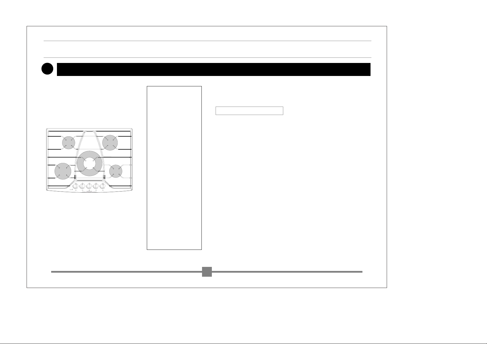
The layout of your hob
1. Burner / control hob
semi-fast
2. Burner / control hob
fast
3. Burner / control hob
large fast
4. Burner / control hob
auxiliary
5. Burner / control hob
double crown
2
4
2
1
3
1
3
4
5
5
Page 4
2
PPaarrtt 11:: FFoorr tthhee uusseer
r
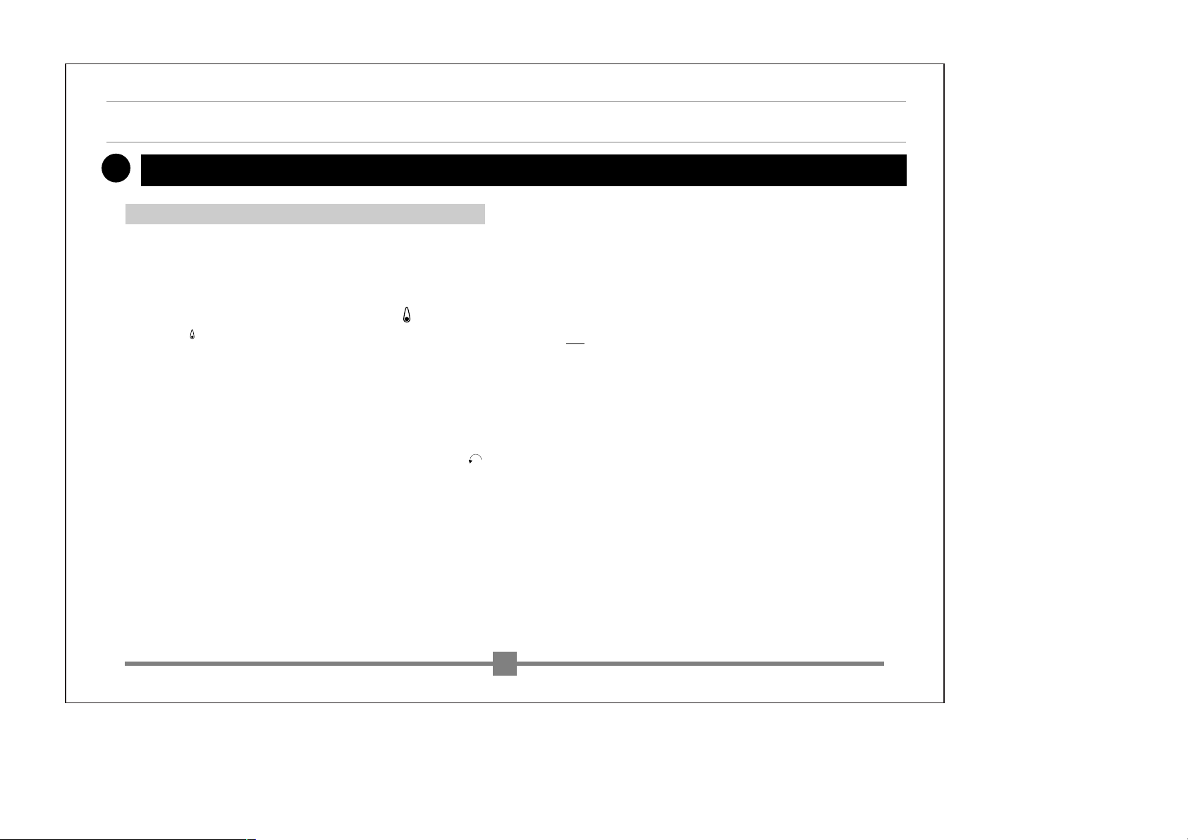
Using the gas burners
•
Each burner is controlled by a tap with a safety locking
device which, in the event of accidental extinction of the
flame (spillage, draught...) quickly cuts off the gas supply
and prevents any from escaping.
A lower setting is achieved between the symbol and
the symbol. The dot (
●) corresponds
to the off position for the knob.
•
Burner safety is effected by a metal rod located directly
adjacent to the flame.
•
Select the burner required, using the symbols located
near the control knobs as a guide.
•
To light a burner, push in the knob and turn it in the
direction to maximum setting.
Maintain pressure for a few seconds after the flame
has appeared, to engage the safety system.
•
In the event of a power cut, a burner can still be lit by placing a lighted match next to it while keeping the corresponding control knob at maximum setting.
In the event of accidental extinction of the flame, just relight in the usual way, following the lighting instructions.
Ignition with gas safety device
NB
: the burner flames nearest to the tips of the pan sup-
port are smaller, to protect the enamel of the pan
support.
Page 5
3
PPaarrtt 11 :: FFoorr tthhee uusseer
r
Using the gas burners
•
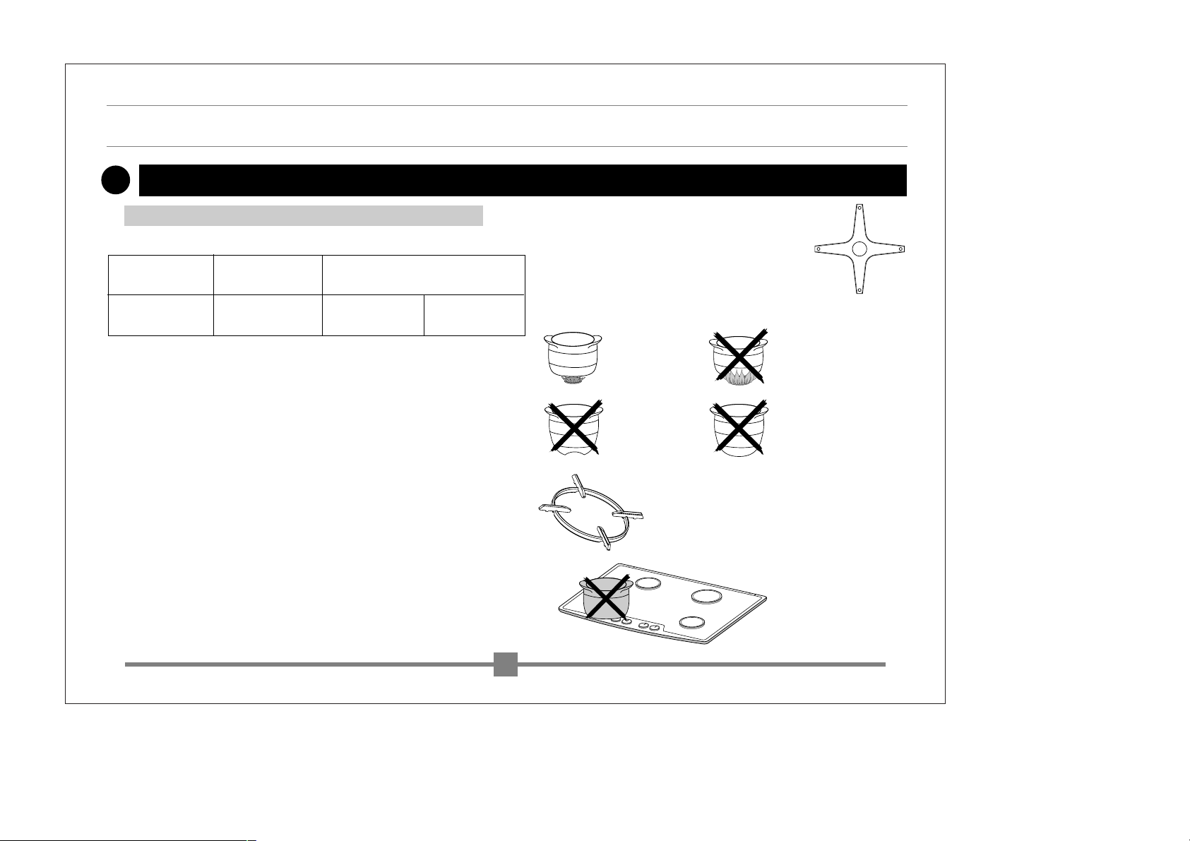
Suggested pan diameters
•
Adjust the burner to prevent the flames from coming up
the side of the pan
•
Do not use pans with a concave or convex base.
•
Only the 5-burner gas hobs are fitted with a special
“WOK” type pan support which can only be used on the
central “Double Crown” burner.This “WOK” pan support
enables the use of pans with a concave base. In combination with the “Double Crown” burner, it enables improved flame distribution around large recipients such as large diameter woks and paella pans.
•
Do not use pans with a large diameter near the control
knobs.
Which pans to use on the gas burners
Small burners Medium burner Large burners
(fast) (Large fast) (Double crown)
12 cm to 24 cm 16 cm to 28 cm 18 cm to 28 cm 20 cm to 30 cm
WRONGRIGHT
CONCAVECONVEX
•
Your appliance is equipped with a removable
support grid for small pans.
It can be used on all the burners of your appliance excepted on the front left large rapid
burner and on the central “double crown” burner of the 5 burner hobs.
Page 6

4
•
Do not store CLEANING PRODUCTS or INFLAM-
MABLE ITEMS in the unit under your hob.
•
Change the gas supply hose before its expiry date.
Usual care
Precautions for use
•
Never clean your hob while it is in operation; however,
cleaning your hob will be made easier if you do this
before it has completely cooled.
•
For cleaning the enamel on the hob or the pan support,
use a cream cleaner. Polish with a dry cloth.
•
To clean the stainless steel areas on the hob, use a sponge and soapy water or a commercial cleaner designed
for stainless steel.
•
Never allow acid liquids such as lemon juice, vinegar
etc., to remain on the enamel.
•
The gas injector is located at the centre of the burner
which is in the form of a pot. Take care never to block it
during cleaning as this will adversely affect your hob's
performance.
•
Use soapy water to clean the burner caps. For stubborn
stains, you can use a small amount of non-abrasive
cream cleaner on a sponge, then rinse with clean water.
Dry the burner caps carefully before using your hob
again. If the burner holes or the igniters become dirty,
clean them using a small, stiff brush.
Care of the gas burners
Care of the enamel on the stainless steel
PPaarrtt 11:: FFoorr tthhee uusseer
r
Cleaning your hob
SAFETY WARNING :
D
ANGER :
D
O NOT SPRAY AEROSOLS IN THE VICINITY OF THIS APPLIANCE
WHILE IT IS IN OPERATION
.
- W
HERE THIS APPLIANCE IS INSTALLED IN MARINE CRAFT OR IN
CARAVANS, IT SHALL NOT BE USED AS A SPACE HEATER.
Page 7

5
•
As a general rule, installation should be carried out by
qualified installers and technicians.
•
Before installation, make sure that local distribution
conditions (gas type and pressure) are compatible
with the appliance's adjustment.
•
This hob has been designed for use by private individuals
in a residential building. Adjustment conditions are noted
on a label enclosed in the wallet and attached to the
packaging.
•
As it is not connected to a device for the evacuation of
the products of combustion, it must be installed in
accordance with current regulations and used in a
well-ventilated location. Particular attention must be paid
to the regulations on ventilation.
•
Further to this, as combustion is only possible due to the
oxygen in air, this air must be constantly renewed and
the products of combustion must be evacuated (an air
flow of 2 m3/hr per kW of power is required).
PPaarrtt 22:: FFoorr tthhee iinnssttaalllleer
r
General information
This hob is rated type X (under standard EN 60.335.2.6) insofar
as the heating of units is concerned.
Building inInstallation
TYPE :
N˚ SER. :
1
2
34
MANUFACTURED BY
Identification plate :
- 1 Serial number.
- 2 Appliance Type.
- 3 Operating voltage.
- 4 Total output.
Warning : keep this instruction book in a safe place near your
appliance with the identification label glued to the cover.
Page 8

6
•
The hob should be fitted into the work surface of a
supporting unit. The work surface must be a minimum of
3 cm thick and made of heat resistant material or
covered with such a material.
•
In order not to make the manoeuvring of pans difficult,
there should not be a unit or a wall to the left or right of
the hob closer than 30 cm.
•
If a horizontal partition is fitted underneath the hob, it
should be located at a distance of 100 to 150 mm from
the top of the work surface. Never place sprays or pressurised containers in any compartment underneath the
hob.
•
Non combustible material to a minimum height of 30 cm.
49 cm
3 cm mini
30 cm mini
30 cm mini
56 cm
5,3 cm mini
70 cm mini
Preliminary remarks
PPaarrtt 22:: FFoorr tthhee iinnssttaalllleer
r
General information
Page 9

7
•
Glue on the seal supplied in the wallet before installing
the hob:
1 - Remove the pan supports, the burner caps and the
burner heads, noting their positioning.
2 - Turn over the hob and place it carefully over the cutout in the unit to avoid damaging the control knobs and
the igniters.
3 - Glue the foam seal, supplied with the appliance, arround the outside edge of the base plate. This seal ensures watertightness with the worktop.
•
Place the hob into the cut-out in the unit, taking care to
centre it properly in the cut-out.
•
Replace the pan support, the caps and the burner heads.
•
Connect the hob’s power supply cable to the mains supply in your kitchen (see “Electrical connection” of the
hob).
PPaarrtt 22:: FFoorr tthhee iinnssttaalllleer
r
Installing the hob
General information
You can immobilise your hob in the worktop in accordance
with the illustration below using the 4 fixing brackets and
screws supplied in the wallet.
Fixing the hob in place
FIXING BRACKET
FIXING BRACKET
APPLIANCE
VIEWED
FROM
BENEATH
FRONT
REAR
WORKTOP
Page 10

8
PPaarrtt 22:: FFoorr tthhee iinnssttaalllleer
r
Electrical connection
•
These hobs are supplied with a power supply cable (ty-
pe H05VVF-T105 or type H05V2V2F-T90, with a cross-section of 1 mm2) with 3 cores (2 phase + earth) and should be
connected to the 230 V mains supply by means of a 2 phase + earth plug and socket conforming to EEC 7 or a double
pole isolator switch with a contact gap of at least 3 mm.
If this power supply cable is damaged, it should only be replaced by your After Sales Service, as special tools are required.
Important note: the earth wire (green/yellow) is connected to the appliance's earth terminal and must be
connected to the mains earth terminal .
H05VVF-T105 cable
or H05V2V2F-T90 cable
Cross-section of cores
in mm2
Fuse
230 V - 50 Hz
Gas
3 cores of which
1 earth
1
10 A
CROSS-SECTION OF CABLE TO BE USED
Page 11

9
•
If the hob is installed above an oven or if the proximity of
other heating elements might cause the connection to
heat up, it is essential that rigid connections are used.
•
Whatever type of connection is chosen, check its
air-tightness after installation using soapy water.
•
Mains gas (natural gas) or LPG.
•
Back right hand corner 1/2 inch male BSP thread.
•
Rigid pipe connection
.
Installation to be in accordance with AG 601.
Make the connection at the end of the elbow fitted onto
the appliance.
PPaarrtt 22:: FFoorr tthhee iinnssttaalllleer
r
Gas connection
Preliminary remarks
Connection options
Page 12

PPaarrtt 22:: FFoorr tthhee iinnssttaalllleer
r
Changing gas
10
•
This hob is supplied pre-adjusted for natural gas.The injectors required for adapting it to butane/propane are in the wallet
with the instruction booklet.
•
Each time the gas is changed, tick the new gas setting on the label to be found in the wallet.
❶
ADAPT THE GAS CONNECTION (P9)
❷
CHANGE THE INJECTORS
❸
ADJUST THE LOW FLAME SETTING OF THE TAPS
❷
CHANGE THE INJECTORS, proceeding as follows :
•
Remove the pan supports and all the burner caps and heads.
•
Fig.1: Using the spanner② provided, unscrew and remove the injec-
tors① located in the bottom of each pot③.
•
Fig.2: Assemble the injectors provided in the pouch and
screw them by hand until blocked.
•
Fig.3: Engage the spanner fully on the injector.
•
Fig.4: Draw a line④ on the base plate with a pencil on the pla-
ce shown.
•
Fig.5: Turn the spanner② until the line④ appears on the other
side of the spanner.
•
Replace the burner heads and caps and the pan supports.
•
Retain the natural gas injectors, replacing them in the wallet.
Changing from natural gas to LPG
Preliminary remarks
Pan support
Cap
Head
Pot
Base plate
①
②
②
③
④
④
fig.1
fig.3
fig.2
fig.4
fig.5
Page 13

11
•
Using the small screwdriver, supplied in the bag,
screw fully the brass, adjustment screw (yellow) (see figure below) clockwise.
•
Replace the airtight seals, then the control knobs, ma-
king sure they turn in the correct direction.
3 -
ADJUST THE LOW FLAME SETTING OF THE TAPS, located un-
der the knobs, proceeding as follows:
•
Remove the control knobs by pulling them upwards.
•
Remove the airtight seals, marking their fitting
direction beforehand: pull the seal upwards, twisting it to
release it.
•
Work on each tap in turn.
PPaarrtt 22:: FFoorr tthhee iinnssttaalllleer
r
Airtight seal
Control
shaft
of tap
Stainless
steel
Changing gas (cont.)
Low flame
adjuster screw
Page 14

12
3 - ADJUST THE LOW FLAME SETTING OF THE TAPS, located un-
der the control knobs, proceeding as follows:
Working on each burner in turn.
•
Light the burner at maximum position.
•
Remove the control knob for the corresponding tap as
well as the airtight seal.
•
Using the screwdriver, supplied in the bag, unscrew
the yellow, brass, adjustment screw (see drawings opposite) turning it round twice, anti-clockwise.
•
Replace the control knob and turn it to low flame setting.
•
Remove the control knob again, then turn the adjuster
screw clockwise to the lowest position before the flame
goes out, replace the control knob and the airtight seal
and turn the tap from full on to low flame several times to
check the adjustment : the flame should not go out ;
otherwise, adjust the setting by tightening or loosening
the adjuster screw slightly until a steady flame is obtained when the knob is operated.
•
Replace the airtight seals and the control knobs, making sure they turn in the correct direction.
To carry out this operation you must do the following in order:
1- ADAPT THE GAS CONNECTION (p.9)
2- C
HANGE THE INJECTORS
3- ADJUST THE LOW FLAME SETTING OF THE TAPS
2 - CHANGE THE INJECTORS, proceeding as follows:
•
Remove the pan supports and all the burner caps and
heads.
•
Using a 7 socket, supplied in the wallet, unscrew the
injectors located in the base of each burner pot and
remove them.
•
Replace them, in accordance with the table on page
14, screwing them down manually, then, using the socket, screw in a quarter turn at the most.
•
Replace the burner heads and caps and the pan
supports.
PPaarrtt 22:: FFoorr tthhee iinnssttaalllleer
r
Changing gas (cont.)
Changing from LPG to natural gas
Page 15

GGaass rraattiinng
g
AAfftteerr--ssaallee sseerrvviicce
e
13
Natural gas
107
133
80
158
166
Low flame
adjuster
screw
Don’t forget me
Page 11
IMPORTANT :
•
To benefit from the guarantee on your hob, do not
forget to have your Guarantee Certificate dated and
signed by your retailer-installer.
•
All repairs must be carried out by a qualified technician. The distributors of our make are the only
people who :
-H
AVE COMPLETE KNOLEDGE OF YOUR APPLIANCE AND
ITS OPERATION
,
-F
ULLY EMPLOY OUR TECHNIQUES OF ADJUSTEMENT,
MAINTENANCE AND REPAIR,
-U
SE EXCLUSIVELY GENUINE SPARE PARTS.
•
Any repair carried out as a result of installation
or use which is not in conformity with the instructions in this booklet will not accepted under
the terms of the manufacturer’s guarantee which will be terminated.
•
In the event of a complaint or to order spare parts
from your distributor, give him the complete reference details for your appliance (appliance model
and type and full serial number). This information
appears on the identification plate fixed to the casing of the appliance or on the guarantee certificate.
•
The descriptions and technical data which appear
in this booklet are for information only and are not
legally binding. In the interests of product quality,
we reserve the right to carry out any necessary
changes and improvements without prior notice.
Réf. : CH80X
CH80W
CH80E
Appliance designed for installation in LPG Natural
Australia : gas
2.75 kPa 1 kPa
F
RONT RIGHT AUXILIARY BURNER
Indicator marked on injector 50 80
Heat output/HCP (MJ/hr) 3.4 3.4
R
EAR RIGHT FAST BURNER
Indicator marked on injector 78 133
Heat output/HCP (MJ/hr) 7.6 8.0
F
RONT LEFT LARGE FAST BURNER
Indicator marked on injector 85 158
Heat output/HCP (MJ/hr) 9.7 11.5
R
EAR LEFT SEMI-FAST BURNER
Indicator marked on injector 62 107
Heat output/HCP (MJ/hr) 4.9 5.4
D
OUBLE CROWN BURNER
Indicator marked on injector 95 166
Heat output/HCP (MJ/hr) 11.5 12.5
107
133
166
158
80
LPG
107
133
80
158
166
62
78
95
85
50
Page 16

W
Waarrrraannttyy aanndd SSeerrvviiccee
In addition to all statutory rights which you, the Consumer, have
under the relevant laws in respect of this appliance, during the
first five years of ownership as the original purchaser of the
Kleenmaid appliance, we guarantee that any fault caused by
faulty material or workmanship becoming apparent will be rectified free of charge for parts and labour, provided that all service
is performed during normal working hours by Kleenmaid or their
designated Agents. Where the appliance is installed outside the
normal servicing area of the above, the Purchaser must pay for
the cost of transporting the appliance to and from the Agent or
the Agent’s travelling cost to and from the Purchaser’s home.
In case of fractured glass do not use your appliance.
Please complete the enclosed warranty card and post it to us
or phone our After Sales Service.
To assist you when phoning our After Sales Service to arrange
a service call please have the following details ready.
Model Number:
Date of Purchase:
Kleenmaid Store purchased from:
Date of installation:
In addition to all statutory rights which you, the Consumer, have under the relevant laws in respect of this appliance, during
your first one year of ownership as the original purchaser of the
Kleenmaid appliance, we guarantee that any fault caused by
faulty material or workmanship becoming apparent, will be rectified free of charge for parts and labour, provided that all service is performed during normal working hours by Kleenmaid or
their designated Agents. Where the appliance is installed outside the normal servicing area of the above,the Purchaser must
pay for the cost of transporting the appliance to and from the
Agent of the Agent’s travelling cost to and from the Purchaser’s
home.
We are not responsible for any damage or malfunction unless
caused by a defect in material or workmanship. This includes,
but is not limited to abuse, misuse, improper installation and
transportation damage. We are not responsible for any consequential damages from any malfunction.
DOMESTIC WARRANTY - Full Five Year Warranty
COMMERCIAL WARRANTY - Full One Year Warranty
WARRANTY REGISTRATION
SERVICE ASSISTANCE
WHAT THESE WARRANTIES DO NOT COVER
KLEENMAID AFTER SALES SERVICE
1300 652 100
WARRANTY DOES NOT COVER REPLACEMENT OF LIGHT
GLOBES OR GLASS BREAKAGE DUE TO IMPACT
87X2214 - 9960-3833 - 05/00
 Loading...