

Page 1
Manual for installation and utilisation
of Gas Cooking Hobs
CH600X, CH600FFX
CH600W, CH600FFW
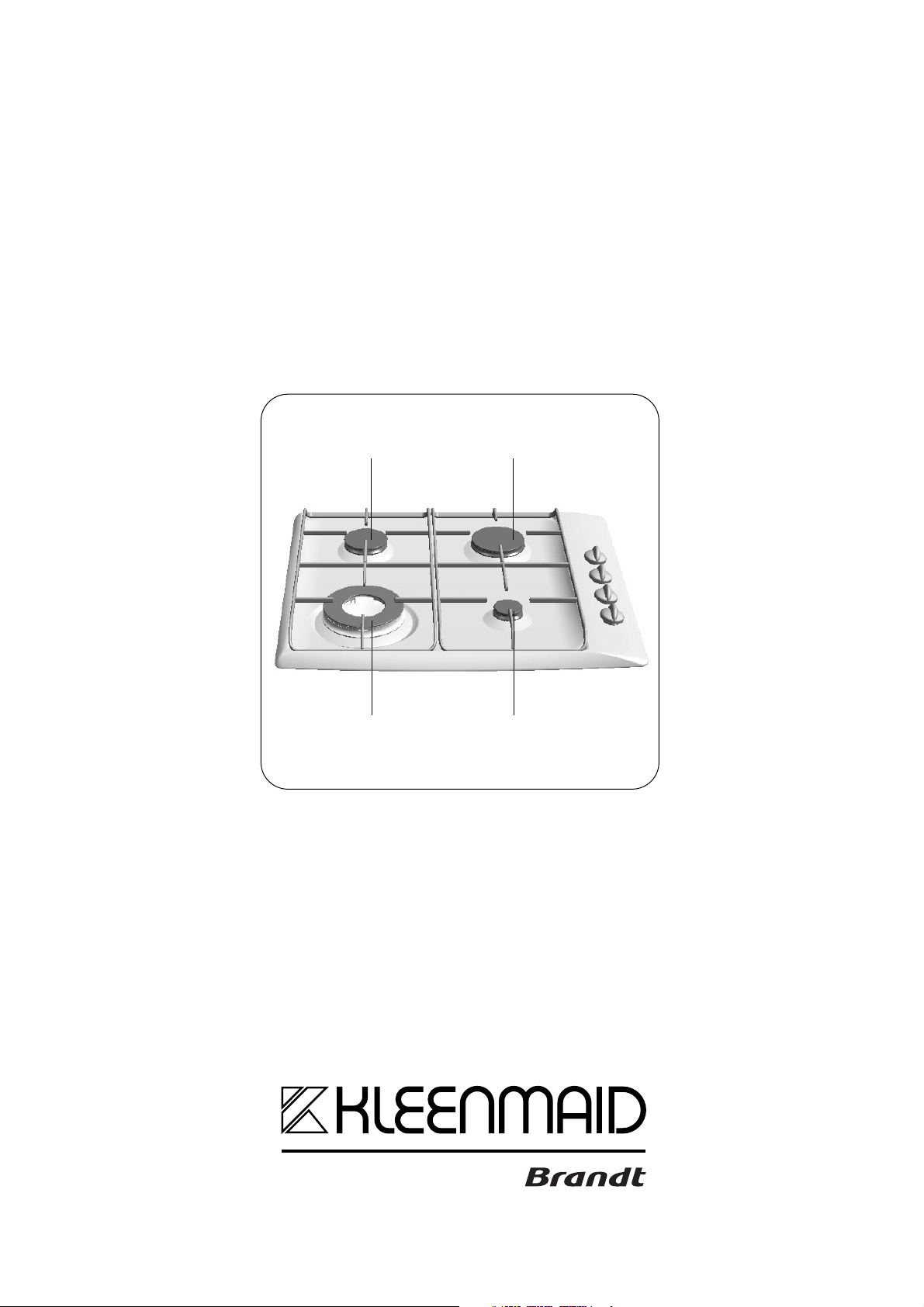
Semi-fast
burner
Double crown
burner
Fast
burner
Auxiliary
burner
MANUFACTURED BY
Page 2
We would like to congratulate you for buying one of our hobs.
To get the best out of your new appliance we strongly advise you to read carefully all the information
contained in this instruction manual :
P AR T 1 FOR THE INSTALLER
GENERAL INFORMATION P.3
BUILDING THE HOB IN P. 3
HOW TO INSTALL THE HOB P. 4
HOW TO FASTEN THE HOB P. 4
HOW TO CONNECT THE COOKING HOB
TO THE ELECTRICAL SUPPLY P. 4
GAS CONNECTION P. 5
HOW TO MAKE THE CHANGE OF GAS TYPE
FOR THE COOKING HOB
GAS RATING P. 11
COOKING GUIDE P. 12
. P. 6-7
Look out for...
P AR T 2 FOR THE USER
HOW TO USE THE GAS BURNERS P. 8
WHICH SAUCEPANS TO USE ON THE GAS BURNERS P. 9
HOW TO CLEAN YOUR HOB P. 10
QUESTIONS/ANSWERS P. 10
AFTER-SALES SERVICE P. 12
tips
warnings
things to read
contacts
YOUR COOKING HOB IS DELIVERED REGULA TED
FOR MAINS GAS (NA TURAL GAS).
Hobs with one or several gas burners must be installed in conformity with current regulations and used solely in an area that is
well aired. These hobs have been designed to be used by householders in domestic premises.
Please read these instructions before installing and using your cooking hob.
With a view to the constant improvement of our products, we reserve the right to make any changes in their technical,
functional or aesthetic characteristics as a result of technical evolution.
These hobs are designed exclusively for the cooking of drinks and foodstuffs.
These products do not contain any asbestos-based component parts.
-2-
Page 3
PPaarrtt 11:: FFoorr tthhee IInnssttaalllleer
This height should be in accordance with
Local Gas Authorities and the manfacturer
of the rangehood
r
●
GENERAL INFORMATION
THIS APPLIANCE SHOULD BE INSTALLED BY A QUALIFIED TECHNICIAN / INSTALLER.
•
•
Prior to installation, ensure that the local
distribution conditions (nature of the gas and gas
pressure) and the adjustment conditions of the
appliance are compatible.
•
These hobs are designed to be used by
private individuals in their homes. the adjustment
conditions are stated on a label in the bag and also on
the packaging.
•
Since this appliance is not connected to a
combustion products evacuation device, it must be
installed in accordance with current installation
regulations and used in a well-ventilated place.
particular attention should be given to the relevant
requirements regarding ventilation.
●
BUILDING THE HOB IN
On this subject, combustion can take place only
if oxygen from the air is present, so this air must be
constantly renewed and the combustion products
must be evacuated (a minimum air input of 2 m3/hour
per kw of gas energy is required)..
•
The hob must be built into the worktop of a
support cupboard. This worktop must be at least 3
cm thick and heat-resistant or else coated with a heat
resistant material.
•
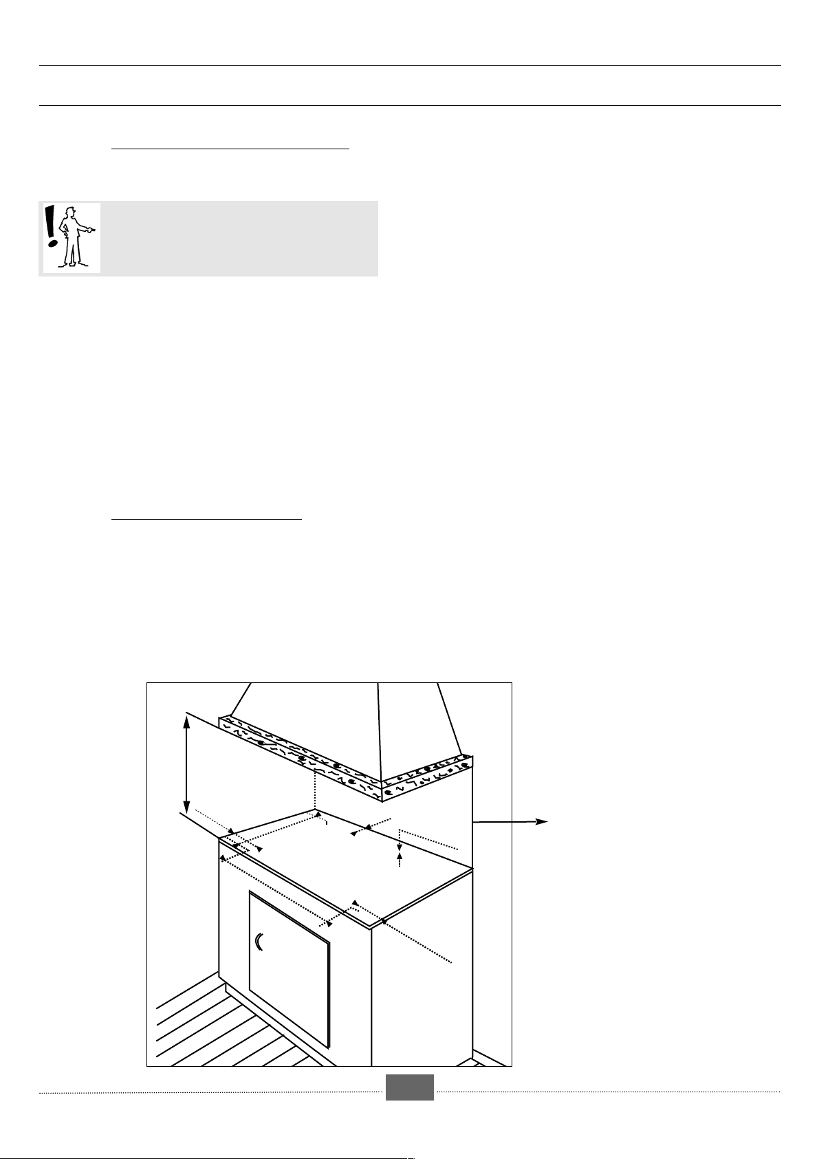
A side-clearance of at least 30 cm should be left
to the right and left of the hob. A tall cupboard or
partition too close to the hob would hinder free
movement of kitchen utensils.
65 cm mini
30 cm mini
49 cm
56 cm
•
must be placed between 10 and 15 cm from the
bottom of the work top. In any case, do not keep any
sprays or pressurized containers in the compartment
which could be just under the hob.
5,3 cm mini
3 cm mini
30 cm mini
If a horizontal partition is put under the hob, it
-3-
Page 4
PPaarrtt 11:: FFoorr tthhee IInnssttaalllleer
r
●
●
HOW TO INSTALL THE HOB
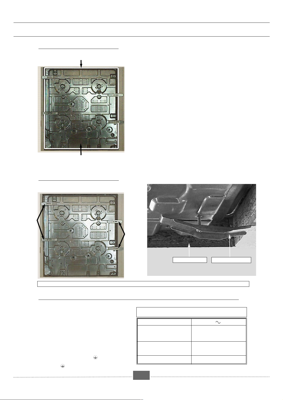
Joint
Under surface of the
hob (carter).
HOW TO FASTEN THE HOB
•
Glue the joint supplied in the sachet before
installing the hob.
Before inserting the hob:
1- Turn over the hob and pose it with precaution
above the opening of the support in order not to
damage the knobs, lighting stubs and the metal gas
security rods.
2- Glue the foam joint delivered with the apparatus to
the external rim of the carter. This joint ensures
sealing between the cooking hob and the work
surface
3- Place the cooking hob in the opening of the support
unit taking care to centre it well in the cut-out..
4- Fit the burner heads, burner caps and the grids..
5- Connect the hob power supply cable to the
electrical installation of the kitchen. See "How to
connect the cooking hob to the electrical supply".
6- Connect the gas. See "How to connect the
cooking hob to mains gas" or "How to connect to
connect the cooking hob to Butane /Propane
gas".
Fastening
bracket
●
Fastening
bracket
Worktop
If you wish to clamp the hob, ensure that the four fixation plates supplied in the sachet are used.
Fastening bracket
HOW TO CONNECT THE COOKING HOB TO THE ELECTRICAL SUPPLY.
•
The cooking hob must be connected to 240v
single phase mains supply by the intermediary of a
two phase + earth homologated EEC 7 plug or a
single pole cut-off device with a contact opening by at
least 3mm.
If the mains connection cable is damaged it must
be replaced by your After-Sales Service
because special tools are needed
Warning: The protection wire (green /yellow) is
connected to the earth terminal of the apparatus
and must be connected to the
earth terminal of the installation.
.
Cable H05V2V2F - T90
.
Cross section of
conductors in mm2
Fusible
CROSS SECTION OF THE CABLE TO USE
Network
240 V - 50 Hz
3 conductors of which 1 is
to be earthed
10 A
1
-4-
Page 5
PPaarrttiiee 11:: FFoorr tthhee IInnssttaalllleer
GAS CONNECTION
●
•
If the hob is installed above an oven or if
the proximity of other heating elements might cause the connection to heat up, it is essential that rigid connections are used.
•
Whatever type of connection is cho-
sen, check its air-tightness after installation
using soapy water.
•
Mains gas (natural gas) or LPG.
•
Back right hand corner 1/2 inch male BSP
thread.
•
Rigid pipe connection.
Installation to be in accordance with AG 601.
Make the connection at the end of the elbow
fitted onto the appliance.
- Duplicate data plates should be
attached to adjacent surfaces
- The operation of the appliance must
be tested before leaving.
- If the appliance cannot be adjusted to
perform correctly contact the local gas authority.
- The test point pressure should be set with the
semi-rapid and the rapid burners operating
at maximum.
r
PRELIMINARY REMARKS
CONNECTION OPTIONS
-5-
Page 6

PRELIMINARY REMARKS
•
Your cooking hob is delivered regulated for
network gas (natural gas).
The injectors necessary for adaptation to LPG can be
found in the bag containing the
manual.
When carrying out this operation, you should
successively:
PPaarrtt 11:: FFoorr tthhee IInnssttaalllleer
ADAPT THE HOB CONNECTION to the new gas adjustment
HOW TO MAKE THE CHANGE OF GAS TYPE FOR THE COOKING HOB
●
r
Disconnect the apparatus before intervention
NETWORK GAS
(NATURAL GAS)
Meter
BUTANE/PROPANE
Pressure regulator
compulsory
propane
butane
propane
fig.1
Injector
Dish
Spanner
Angle spanner
Hearthplate
fig.2
Line
CHANGING FROM NETWORK GAS (NATURAL
GAS - AN AIR PROPANE / BUTANE MIXTURE
TO THE BUTANE/PROPANE GAS (FIG. 1)
➊
ADAPT THE GAS CONNECTION
❷
CHANGE THE INJECTORS
❸
ADJUST THE RETARDER ON THE TAPS
➊
Refer to the paragraph “Gas connection”.
❷
CHANGE THE INJECTORS in the following way:
•
Remove the supports, and all the burner caps and
heads.
•
Using the spanner supplied, unscrew the injectors
at the bottom of each dish and remove them (fig. 2).
•
Replace these with the injectors supplied in the
bag, in accordance with the gas characteristics
table; To do this:
➪ First, screw them by hand.
➪ Put the spanner well onto the injector.
➪ Screw them right in without forcing.
➪ With a pencil draw a line on the hearth plate as
ndicated (fig. 3).
➪ Turn the spanner clockwise until the line appears on
the other side (fig. 4).
•
Remount the heads, caps and grids of all the
burners.
Tap axis
fig.5
Adjustment
screw
❸
ADJUST THE RETARDER ON THE TAPS located under the
knobs. Proceed as follows:
•
Pull up the knobs and remove them.
•
Using a small screwdriver, screw fully the brass,
adjustment screw (yellow) (fig.5) clockwise.
•
Work on one tap at a time.
•
Put the knobs back in place making sure they are
turned in the right direction.
-6-
Page 7

PPaarrtt 11:: FFoorr tthhee IInnssttaalllleer
- ADAPT THE HOB CONNECTION to the new gas
HOW TO MAKE THE CHANGE OF GAS TYPE FOR THE COOKING HOB
●
r
Disconnect the apparatus before intervention
NETWORK GAS
(NATURAL GAS)
Meter
Injector
Dish
Spanner
BUTANE/PROPANE
Pressure regulator
compulsory
butane
propane
Angle spanner
Hearthplate
propane
Line
fig.1
fig.2
CHANGING FROM BUTANE / PROPANE GAS
TO NETWORK GAS (NATURAL GAS) (FIG. 1)
When carrying out this operation, you should
successively:
➊
ADAPT THE GAS CONNECTION
❷
CHANGE THE INJECTORS
❸
ADJUST THE RETARDER ON THE TAPS
➊
adjustment. Refer to the paragraph “Gas connection"
❷
CHANGE THE INJECTORS in the following way:
•
Remove the supports, and all the burner caps and
heads.
•
Using the spanner supplied, unscrew the injectors
at the bottom of each dish and remove them (fig. 2).
•
Replace these with the injectors supplied in the bag, in
accordance with the gas characteristics table at the
end of this instruction manual. To do this:
➪ First, screw them by hand.
➪ First, screw on the injector tightly by hand.
➪ Screw them right in without forcing.
➪ With a pencil draw a line on the hearth plate as
ndicated (fig. 3).
➪ Turn the spanner clockwise until the line appears on
the other side (fig. 4).
•
Remount the heads, caps and grids of all the
burners.
fig.3
Tap axis
fig.5
Line
fig.4
Adjustment
screw
Spanner
❸
ADJUST THE RETARDER ON THE TAPS located under
the knobs. Proceed as follows:
•
Work on one burner at a time:
- light the burner and turn the knob to maximum
position
- remove the knob of the corresponding tap,
- using a screwdriver, unscrew the yellow, brass, adjustment screw (fig.5) turning it round twice, anti-
clockwise.
- put back the knob, and turn it to minimum
position,
- emove the knob again then turn the adjustment
screw clockwise as low as possible without
extinguishing the flames,
- put back the knob then turn it several times from
maximum position to minimum position : the fla-
me must not be extinguished. Otherwise, re-adjust it by slightly screwing or unscrewing the
adjustment screw so that a stable flame is
obtained when the knob is turned from maximum
to minimum position.
-7-
Page 8

PPaarrtt 22:: FFoorr tthhee UUsseer
Do not spray aerosols in the vicinity of this appliance while it
is in operation. Where this appliance is installed in in
marine craft or in caravans, it shall not be used as a space
heater.
HOW TO USE THE GAS BURNERS
●
r
LIGHTING THE HOB WITHOUT GAS SECURITY DEVICE
(DEPENDING ON MODEL)
•
Select the required burner by referring to the
symbols located near the knobs (e.g: for the
front right-hand burner).
•
Each burner is supplied by a tap. To turn this on,
press it down and turn it anti-clockwise .
The gas is turned off when the knob points to (●)
•
To turn the gas down he knob should be tur-
ned from to .
•
Your hob is equipped with a burner ignition
device integrated into the knobs: To ignite a burner,
press down and turn the knob anti-clockwiseuntil
it is pointing to the maximum position .
LIGHTING THE HOB WITH GAS SECURITY DEVICE
(DEPENDING ON MODEL)
Select the required burner by referring to the symbols located near the knobs (e.g. : for the
front right-hand burner).
•
A tap equipped with a gas safety device
controls each burner and if the flame is
accidentally extinguished (spills, draughts etc…)
this device automatically closes down the gas
supply and prevents gas escaping.
•
Your hob is equipped with a burner ignition
device integrated into the knobs.
•
To ignite a burner, press down and turn the
knob anti-clockwise until it is pointing to
the maximum position
•
To turn the gas down the knob should be
turned from to
Keep the knob pressed down to activate a
series of sparks until the burner lights.
Ignition
plug
Gas safety
device
(depending
on model)
NOTE :
■ If the flame is accidentally extinguished just re-light it normally following the ignition instructions.
■ Your hob is equipped with an integrated ignition device ; it is, therefore, normal that a series of sparks is produced
on all the burners.
■ If it becomes difficult to turn a knob DO NOT FORCE IT. Have the installer see to it immediately.
■ In the case of a power cut, automatic lighting will not work. In these circumstances, matches may be used
When the flame appears keep the knob well
pressed down for 3 to 5 seconds to activate
the safety device.
-8-
Page 9

PPaarrtt 22:: FFoorr tthhee UUsseer
r
●
CHOOSING THE RIGHT SAUCEPAN FOR THE GAS BURNERS
•
Use saucepans with the following diameters
Auxiliary
burner
12 to 16 cm
RIGHT
CONVEX CONCAVE
Semi-fast
14 to 22 cm
WRONG
burner
Fast
burner
16 to 26 cm
Double crown
burner
20 to 30 cm
•
Adjust the flames so that they do not lick up
the side of the saucepan.
•
Do not use a saucepan with a convex or
concave base
•
Do not leave an empty saucepan on the gas.
•
Do not use saucepans that partially cover the
knobs.
•
Only cooking tables with "Double crown"
burners are equipped with a specific "Wok" grid
support.
Wok grid
This grid allows using receptacles with a concave
bottom. Associated with a "Double crown" burner,
it gives a better distribution of flames over large
receptacles such as Woks.
RECOMMANDATIONS :
■ Using a gas-cooking appliance produces heat and humidity in the room in which it is installed. Your kitchen
should be well ventilated.
Keep all natural vents open or install a mechanical ventilation device (mechanical cooker hood).
■ Intensive and prolonged use of the appliance may necessitate extra ventilation - opening a window for example
or producing more efficient ventilation by increasing the power of the existing mechanical ventilation (a minimum
air input of 2 m3/hour per kW of gas energy is required).
■ As a safety measure, remember to turn offthe network gas mains or the tap on the butane/propane cylinder after use.
-9-
Page 10

PPaarrtt 22:: FFoorr tthhee UUsseer
r
●
HOW TO CLEAN YOUR HOB.
It is easier to clean your hob before it has completely cooled. However, you should never clean your appliance while it is on. Turn all the switches to the zero position.
MAINTENANCE OF THE PAN
SUPPORTS AND GAS
BURNERS
QQuueessttiioonnss // aannsswweerrs
Q
UESTIONS
HOW TO PROCEED
• For difficult stains use a non-abrasive paste, then
rinse with clean water. Wipe the burner caps
carefully before using your hob again. If the gas
holes on the burner get clogged or the ignition
plugs get dirty clean them with a small hard-bristled
brush (non-metallic).
•The gas injector is the pot-shaped part in the middle
of the burner. Be careful not to obstruct it when cleaning, as this would interfere with the performance of
your hob.
s
PRODUCTS AND
ACCESSORIES TO USE
•A mild paste cleaner.
•Kitchen sponge.
•Small hard-bristled brush
A
NSWERS
•
Lighting the burners:
- When the knob or button is pressed, there are no sparks,
- When one knob is pressed, the ignition plugs spark on all the
burners at once,
- There are sparks but the burners do not light.
•
The retarder ( reduced flow) on the burners does not stay
alight or else is too strong.
●DEFECTS IN APPEARANCE THAT DO NOT LEAD TO THE NON-FUNCTIONING OF THE HOB OR THE IMPOSSIBILITY OF USING IT ARE
NOT COVERED BY THE GUARANTEE
.
- Check the electrical connection of the hob.
- Check that the ignition plugs are clean.
- Check that the burners are correctly assembled and clean.
- This is normal. The ignition function is centralised and controls all the burners simultaneously.
- Check that the gas supply has been turned on.
-If your gas is supplied by a bottle or a tank, check that these are not empty.
- If you have just installed the hob or changed the bottle of gas, keep the
knob pressed down and turned to the highest position for 3 to 5 seconds
until the gas reaches the burners.
Light the burner by placing the knob between maximum and
minimum gas flow .
Check that the injectors fitted correspond to the gas being used (see the
markings on the injectors: chapter, "Gas characteristics" at the end of part
one).
Remember: the hob comes pre-adjusted for mains gas (natural
gas).
- Check that the retarders have been adjusted correctly (see the
chapter "Changing the gas" in instruction manual).
RECAUTIONS: Do not arrange cleaning products or inflammable products (aerosols or recipients under
P
pressure) in the support furniture under the cooking hob. This also applies to paper and cookery books.
-10-
Page 11

GGaass rraattiinng
g
AUSTRALIA
Appliance designed for installation LPG NATURAL
in AUSTRALIA : GAS
2.75 kPa 1 kPa
AUXILIARY BURNER
Indicator marked on injector 50 80
Heat output/HCP (MJ/hr) 3.4 3.4
FAST BURNER
Indicator marked on injector 78 133
Heat output/HCP (MJ/hr) 7.6 8.0
SEMI-FAST BURNER
Indicator marked on injector 62 107
Heat output/HCP (MJ/hr) 4.9 5.4
DOUBLE CROWN BURNER
Indicator marked on injector 95 160
Heat output/HCP (MJ/hr) 11.5 12
NATURAL GAS
107
160
133
80
62
95
LPG
78
50
-11-
Page 12

CCooookkiinngg gguuiiddee:
WARRANTY AND SERVICE
DOMESTIC WARRANTY - Full Five Year Warranty
In addition to all statutory rights which you, the Consumer, have under the relevant laws in respect of this appliance,
during the first five years of ownership as the original purchaser of the Kleenmaid appliance, we guarantee that any fault
caused by faulty material or workmanship becoming apparent will be rectified free of charge for parts and labour, provided that all service is performed during normal working hours by Kleenmaid or their designated Agents. Where the appliance is installed outside the normal servicing area of the above, the Purchaser must pay for the cost of transporting
the appliance to and from the Agent or the Agent’s travelling cost to and from the Purchaser’s home.
COMMERCIAL WARRANTY - Full One Year Warranty
In addition to all statutory rights which you, the Consumer, have under the relevant laws in respect of this appliance,
during your first one year of ownership as the original purchaser of the Kleenmaid appliance, we guarantee that any fault
caused by faulty material or workmanship becoming apparent, will be rectified free of charge for parts and labour, provided that all service is performed during normal working hours by Kleenmaid or their designated Agents. Where the appliance is installed outside the normal servicing area of the above,the Purchaser must pay for the cost of transporting
the appliance to and from the Agent of the Agent’s travelling cost to and from the Purchaser’s home.
WHAT THESE WARRANTIES DO NOT COVER
We are not responsible for any damage or malfunction unless caused by a defect in material or workmanship. This includes, but is not limited to abuse, misuse, improper installation and transportation damage. We are not responsible for
any consequential damages from any malfunction.
WARRANTY DOES NOT COVER REPLACEMENT OF LIGHT GLOBES OR GLASS BREAKAGE DUE TO IMPACT
In case of fractured glass do not use your appliance.
WARRANTY REGISTRATION
Please complete the enclosed warranty card and retain it with your receipt of purchase.
SERVICE ASSISTANCE
To assist you when phoning our Customer Call Centre number to arrange a service call please have the following details ready.
Model Number: ................................................................................................................................................................................
Date of Purchase: .............................................................................................................................................................................
Kleenmaid Store purchased from: ....................................................................................................................................................
Date of installation: ...........................................................................................................................................................................
KLEENMAID APPLIANCE SERVICE & SPARE PARTS
CONTACT NUMBER 1300 652 100
PLEASE NOTE: ALL SERVICING SHALL BE CARRIED OUT ONLY BY AUTHORISED PERONNEL.
:
Réf. : CH600/*
DEPENDING ON MODEL
PREPARATIONS TIME DOUBLE EXTRA FAST SEMI- AUXILIARY
SOUPS
FISH C
SAUCES H
VEGETABLES E
MEAT Steak X X
FRYING
DESERTS
ROTHS
B
HICK SOUPS
T
OURT-BOUILLON
RILLED
G
OLLANDAISE, BEARNAISE
B
ECHAMEL, AURORE
SPINACH
NDIVES
,
EAS IN SAUCE
P
ROVENCE TOMATOES
P
RIED POTATOES
F
ASTA
P
B
LANQUETTE
RIED ESCALOPE
F
T
OURNEDOS
HIPS
C
RITTERS
F
ICE PUDDING
R
TEWED FRUIT
S
ANCAKES
P
C
HOCOLATE
USTARD
C
C
OFFEE(SMALL COFFEE-POT
, O
SSO-BUCCO
(CAST IRON GRILL)
8-10
MINUTES
8-10
MINUTES
8-10
MINUTES
10
MINUTES
25-30
MINUTES
15-20
MINUTES
90
MINUTES
10-12
MINUTES
10
MINUTES
25
MINUTES
3-4
MINUTES
3-4
MINUTES
10
) X
MINUTES
CROWN FAST FAST
XX
XX
XX
XX
XX
XX
XX
PPaarrtt 22:: AAfftteerr--SSaalleess SSeerrvviiccee
X
X
XX
XX
XX
XX
XX
X
X
XX
XX
XX
X
X
-12-
9961-8632 - 10/00
Page 13

ongratulations on the purchase of your new appliance. This appliance
has been designed and manufactured to give you years of reliable
C
install your new appliance. Correct installation will avoid delays and
unnecessary service calls.
Once installation is complete, read this booklet carefully and get to know the
controls and the features of your new appliance.
We reserve the right to alter the specifications with no influence on the
operation of the appliance. This instruction manual cannot be reason for
claim.
performance. For best results, carefully read the instructions on how to
For appliance please phone
1300 652 100
Kleenmaid St George Store
131308
Page 14

Other products in Kleenmaid St George
range of world’s best appliances:
Washers
Dryers
Dishwashers
Ovens
Cooktops
Rangehoods
Sinks
Waste Disposals
Taps
Cookware
Refrigerators
Freezers
Vacuum Cleaners
For sales information on the full range of quality kitchen and laundry
appliances, phone 13 13 08.
For service related enquires, phone 1300 652 100
 Loading...