

Page 1
ELECTRIC HOB
OPERATING AND
INSTALLATION INSTRUCTIONS
9961-8621 - 09/00
MANUFACTURED BY
RATING PLATE:
CH600SW
CH600SX
DB00645-00-1
Page 2
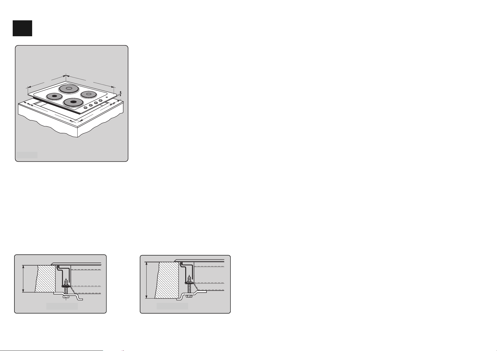
INTO THE WORKTOP
All our cooking hobs are designed to be
fitted into worktops, whether made of
wood or laminated plastic, provided it is
of a heat resistant surface. For building
in it is sufficient to make a hole in the
worktop as shown in Fig. 1 (560 mm x
490 mm) keeping a minimum distance
of 40/50 mm from the rear and from the
right wall and 40 mm from the side
walls to avoid damage by heat.
It is necessary to place a shelt beneath
the hob top, at a distance of at least
90 mm below that of the work surface.
Installation:
If there is a false floor under the hob, it has to be removable for installation purposes.
Insert hob into the worktop opening from above. Make sure that the hob connection cable is
directed to the rear.
Using 4 brackets, tension hob against the worktop in such a way that the entire seal fits tightly
to the worktop.
1
DB00662-00-1
30
DB00663-00-1
40
Figure 2 a
Figure 2 b
FOR THE INSTALLER
POSITION OF TENSIONING BRACKETS
2
GB
Figure 1
DB00642-00-
510
50
560
580
min 60
490
35
Page 3
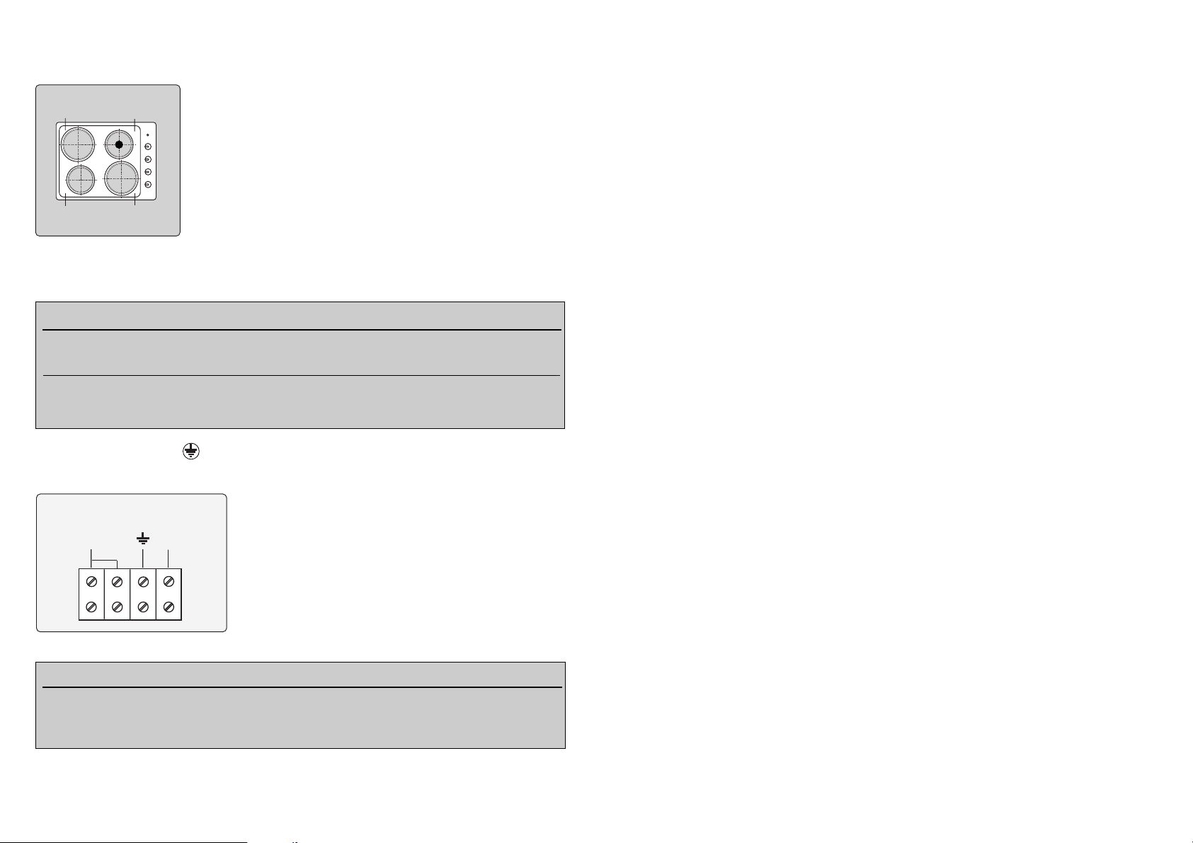
The present hob has 4 tensioning brackets with fastening claws. For their positions see figure
below.
Warning:
For safety purposes, the delivered tensioning brackets must be
used. The contact protection is guaranteed only after installation!
Do not use the hob before it has been built-in. The surfaces of
heating and cooking appliances become hot when in use.
Therefore keep children away. Be careful when preparing food in
hot fat or oil because overheated fat or oil could catch fire easily!
Do not leave the appliance unattended when preparing food
with fat or oil (e.g. chips)!
The mains cables of other appliances (e.g. hand mixers) must not
get into contact with the hot hob surface.
The following cable types can be used for connecting to the mains:
The line marked green and yellow (PE) is to be connected to the terminal showing the protective conductor symbol !
Connect the mains cable in the appliance as follows:
Depending on the power and type of connection, the
appliance has to be fuse - protected by the installation of
the house as follows:
The electric installation of the house must provide an allpole isolator with a minimum contact gap of 3 mm (e.g.
line safety switch, circuit-breaker, contactor).
If the appliance is provided with a superposed residual-current-operated breaker, this breaker has to be sensitive to
pulsed currents.
The protection against accidental contact is only effective after the appliance has been completely built-in.
1
CONNECTION TO MAINS
3
Figure 3
connection type power as per nameplate fuse
220-240 V
~
5,0 kW 1 x 16 A
220-240 V
~
5,5 ............7,0 kW 1 x 25 A
Figure 4
connection type cable type
400 V 2 N
~
H 05 RR F4G 1,5 (4 x 1,5 mm2) or
(two-phase) H 05 VV F4G 1,5 (4 x 1,5 mm2)
220-240 V
~
H 05 RR F3G 2,5 (3 x 2,5 mm2) or
(single-phase) H 05 VV F3G 2,5 (3 x 2,5 mm2)
X
X
X
X
DB00641-00-
220 V-240 V
L
~
DB00648-00-1
N
Page 4

To obtain good cooking results, it is important to use high-quality pots with an even
bottom suited for electric hobs. Make sure
that the diameter corresponds to the size of
the hotplate (1).
Pots with an uneven bottom (2 + 3) consume unnecessarily more energy, cause
overheating of the hotplate and thus reduce
its lifetime.
Too small pots (4) cause a considerable loss
of heat = waste of energy. Besides, spilt food
might get the hotplate dirty and encrusted.
If the pot is too big for the hotplate, the bottom of the pot might get damaged (5).
Hotplates turned on without a pot (6) can
overheat so much that their surfaces develop
cracks, which might lead to total destruction
of the plate.
Size relation of hotplate and pots:
hotplate 145 mm Ø 180 mm Ø
bottom of pot 160 mm Ø 200 mm Ø
Use mild cleaning agents only. Do not scour or scratch. Do not use steam cleaners. They could
cause water to enter the appliance, which is a safety risk.
Since the nameplate on your appliance with all the important data and information is no more accessible
after building in, we have enclosed a second nameplate. It is self-adhesive. Please stick onto the installation instructions to make it available whenever you need the appliance data.
If the power cord of the appliance is damaged, it has to be replaced by a qualified person only.
1
2
3
4
56
CHOOSING THE RIGHT POTS AND PANS
CLEANING
NAMEPLATE
Figure 5
4
Page 5

WARRANTY AND SERVICE
DOMESTIC WARRANTY - Full Five Year Warranty
In addition to all statutory rights which you, the Consumer, have under the relevant laws in
respect of this appliance, during the first five years of ownership as the original purchaser of
the Kleenmaid appliance, we guarantee that any fault caused by faulty material or
workmanship becoming apparent will be rectified free of char ge for parts and labour, provided
that all service is performed during normal working hours by Kleenmaid or their designated
Agents. Where the appliance is installed outside the normal servicing area of the above, the
Purchaser must pay for the cost of transporting the appliance to and from the Agent or the
Agent’s travelling cost to and from the Purchaser’s home.
COMMERCIAL WARRANTY - Full One Year Warranty
In addition to all statutory rights which you, the Consumer, have under the relevant laws in
respect of this appliance, during your first one year of ownership as the original purchaser of
the Kleenmaid appliance, we guarantee that any fault caused by faulty material or
workmanship becoming apparent, will be rectified free of charge for parts and labour,
provided that all service is performed during normal working hours by Kleenmaid or their
designated Agents. Where the appliance is installed outside the normal servicing area of the
above,the Purchaser must pay for the cost of transporting the appliance to and from the Agent
of the Agent’s travelling cost to and from the Purchaser’s home.
WHAT THESE WARRANTIES DO NOT COVER
We are not responsible for any damage or malfunction unless caused by a defect in material
or workmanship. This includes, but is not limited to abuse, misuse, improper installation and
transportation damage. We are not responsible for any consequential damages from any
malfunction.
WARRANTY REGISTRATION
Please complete the enclosed warranty card and retain it with your proof of purchase.
SERVICE ASSISTANCE
To assist you when phoning our Customer Call Centre number to arrange for a service call
please have the following details ready.
Model Number: ...........................................................................................................................
Date of Purchase: .......................................................................................................................
Kleenmaid Store purchased from: ..............................................................................................
Date of installation: .....................................................................................................................
KLEENMAID APPLIANCE SERVICE & SPARE PARTS
CONTACT NUMBER 1300 652 100
5
Page 6

ongratulations on the purchase of your new appliance.
This appliance has been designed and man u factur ed
C
results, carefully read the instructions on how to install your
new appliance. Correct installation will avoid delays and
unnecessary service calls.
Once installation is complete, read this booklet carefully and
get to know the controls and the features of your new
appliance.
We reserve the right to alter the specifications with no
influence on the operation of the appliance. This instruction
manual cannot be reason for claim.
to give you years of reliable performance. For best
For appliance please phone
1300 652 100
Kleenmaid St George Store
131308
Page 7

Other products in Kleenmaid St George
range of world’s best appliances:
Washers
Dryers
Dishwashers
Ovens
Cooktops
Rangehoods
Sinks
Waste Disposal
Taps
Cookware
Refrigerators
Freezers
Vacuum Cleaners
For sales information on the full range of quality kitchen
and laundry appliances, phone 13 13 08.
For service related enquires, phone 1300 652 100
 Loading...