

Page 1

Instructions for installing
and using
your vitroceramic hob
hob
reference CH 600 CE
Page 2
PART 2 FOR THE USER
HOW TO USE THE ZONES P. 8
SAFETY P. 9
QUESTIONS AND ANSWERS P. 9
HOW TO CLEAN YOUR COOKING HOB P. 10
PRECAUTIONS FOR USE P. 11
COOKING TIPS AND GUIDE P. 12-13
VOTRE TABLE DE CUISSON EST LIVRÉE
PREREGLEE POUR LE GAZ DE RESEAU ( GAZ NATUREL)
PART 1 FOR THE INSTALLER
WHAT YOUR HOB LOOKS LIKE P. 3
HOW A VITRO
-CERAMIC HOB WORKS P. 3
GENERALINFORMATION P.4
FITTINGINTOAUNITP. 4
FIXING CLIPS P. 5
CHOOSING YOUR INSTALLATION P
.6
CHARACTERISTICS P. 7
HOW TO CONNECT YOUR COOKING HOB P. 7
These hobs have been designed for private use in the home.
Please read these instructions before installing and using your hob.
With a view to the constant improvement of our products, we reserve the right to make any changes in their
technical, functional or aesthetic characteristics as a result of technical evolution.
These hobs are designed exclusively for the cooking of drinks and foodstuffs.
These products do not contain any asbestos-based component parts.
-2-
Look out for
tips
warnings
things to read
contacts
Page 3
PPPPrrrreeeesssseeeennnnttttaaaattttiiiioooonn
nn
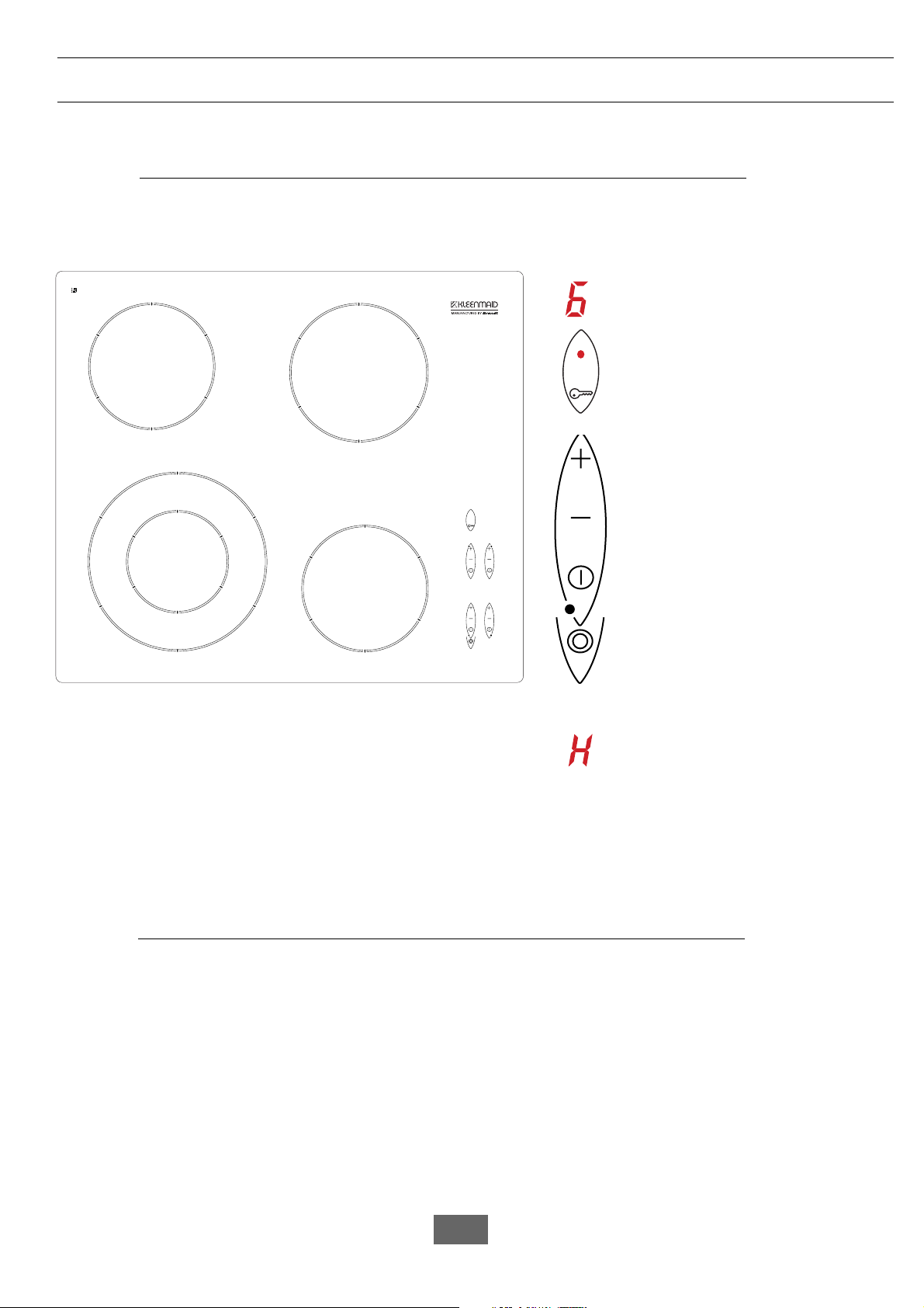
WWHHAATT YYOOUURR HHOOBB LLOOOOKKSS LLIIKKEE
●●
1800 W
Indicator (1 to 9) of power required for
each heating zone.
Lock indicator
Lock key
Adjustment of power (+ or -) for each
heating zone.
On/off control for each heating zone.
Symbol indicating the heating zone on
the hob.
start key for the additional zone
Residual heat indicator
1200 W
1200 W
750/2200 W
The FAST RADIANT rings are comprised of a ribbon heating element fitted with a temperature limiter.
These rings transmit heat by conduction to the vitro-ceramic glass, to the pan, and then to the food.
HHOOWW AA VVIITTRROO--CCEERRAAMMIICC HHOOBB WWOORRKKSS
●●
-3-
1
2
1
2
3
3
Page 4
Please keep to the following points most carefully :
PPPPaaaarrrrtttt 1111:::: FFFFoooorrrr tttthhhheeee iiiinnnnssssttttaaaalllllllleeeerr
rr
•
The hob should not be fitted above a washing
machine, a fridge or a freezer.
•
Wall surfaces above the work surface and in
the immediate vicinity of the cooking hob must be
heat resistant.
•
Laminated surfaces and the adhesive used
for fixing them must be heat resistant in order to
avoid any damage.
•
Protection of cut-outs:
The chipboard used for work surfaces swells
relatively quickly when in contact with dampness.
Apply a varnish or a special glue to the edges of the
cut-out to protect them from dampness or
condensation which may occur underneath the work
surface underneath the table.
Protection against overheating - type Y -
to CEI 335-2-6.
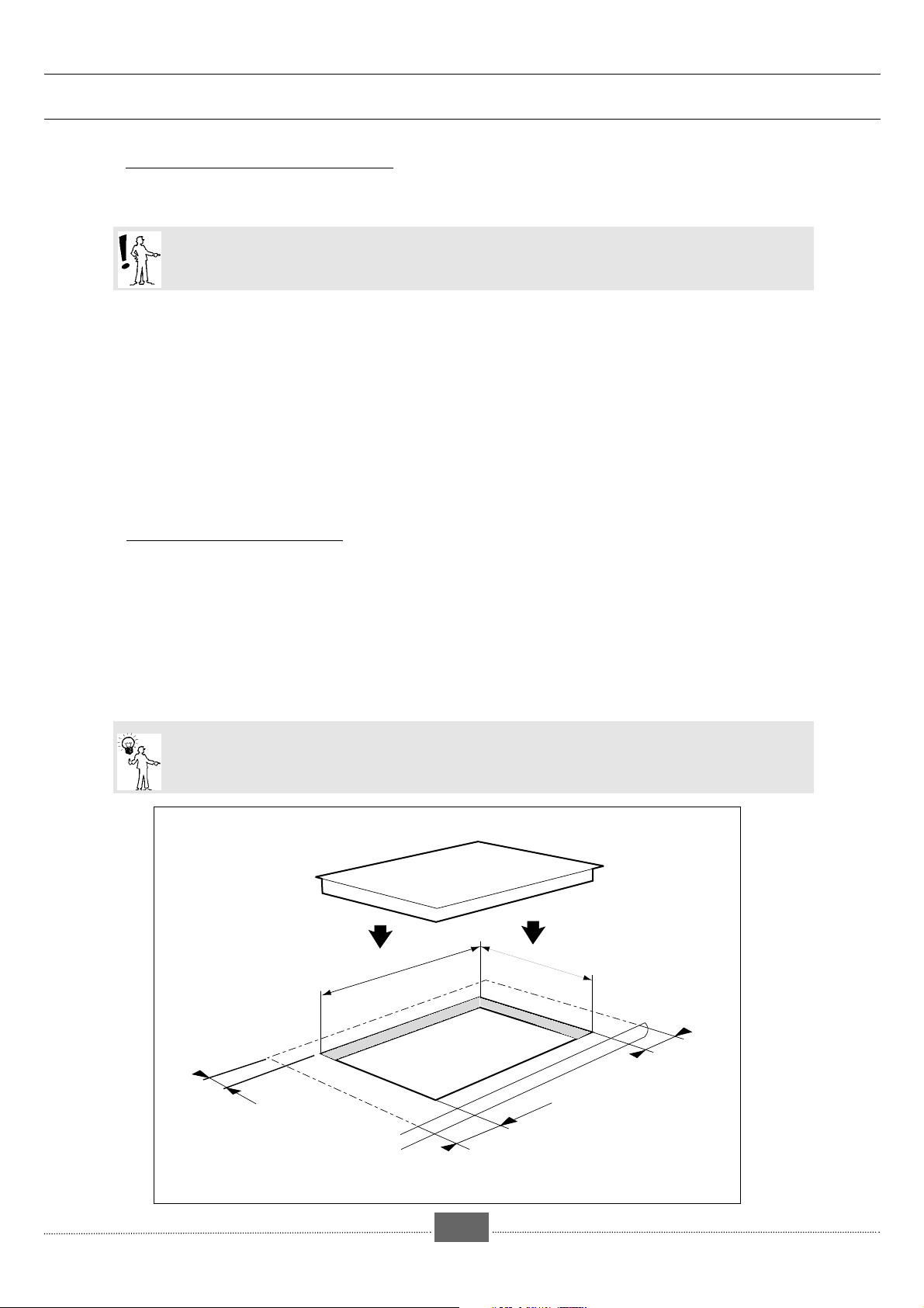
•
Cut a hole in the work surface to the required
size. The measurement of at least 40 mm should be
measured from the wall and the sides (rear and/or
sides).
•
The cooking hob should be fitted into the top
surface of a unit at least 3 cm thick, in heat-resistant
material or surfaced with heat-resistant material.
•
To fix the hob, use the fasteners which you will find
in the wallet .
•
Stick the seal under the hob to ensure a watertight
seal between the hob and the work surface (see
fig. below).
-4-
FITTING SHOULD NORMALLY ONLY BE CARRIED OUT BY A QUALIFIED FITTER OR TECHNICIAN.
GGEENNEERRAALL IINNFFOORRMMAATTIIOONN
●●
FFIITTTTIINNGG IINNTTOO AA UUNNIITT
●●
So that cooking utensils can be used easily, there should be no unit or vertical surface within 30 cm of the
cooking hob.
49 cm
56 cm
4 cm mini
4 cm mini
4 cm mini
Page 5
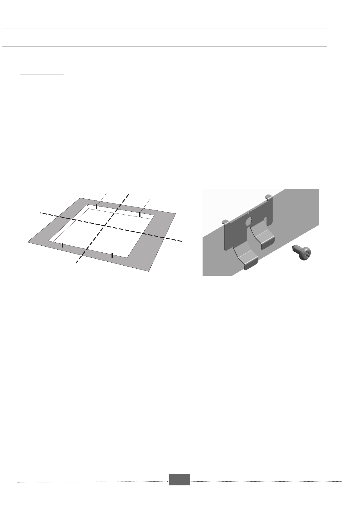
Fixing clips
Screw the clips as shown on
drawing below
PPPPaaaarrrrtttt 1111:::: FFFFoooorrrr tttthhhheeee iiiinnnnssssttttaaaalllllllleeeerr
rr
-5-
600
216
216
Page 6

● over an empty unit or drawer
● over an oven
CCHHOOOOSSIINNGG YYOOUURR IINNSSTTAALLLLAATTIIOONN
●●
Over an empty unit or drawer
The hob may be fitted directly into the work surface over an oven in the upper position (minimum
distance 10 mm).
Vitro-electronic hobs are fitted with thermal security devices for protection in the event of
overheating; these put the hob on "hold" while it cools down.
Over an oven
vide
sanitaire
AVANT MEUBLE
10 mm
FRONT OF UNIT
Gap
-6-
Page 7

-7-
HHOOWW TTOO CCOONNNNEECCTT YYOOUURR CCOOOOKKIINNGG HHOOBB TTOO TTHHEE PPOOWWEERR SSUUPPPPLLYY
●●
PPPPaaaarrrrtttt 1111:::: FFFFoooorrrr tttthhhheeee iiiinnnnssssttttaaaalllllllleeeerr
rr
When your hob is first
connected, or after a
lengthy power failure,
coded lights appear on
the control panel. These
disappear automatically
after about 30 seconds, or as soon as
any of the controls are touched. This
display is perfectly normal; if
necessary, it provides information for
your After-Sales Service.
Operating voltage..........................................................................
Total electrical power absorbed..................................................
Dimensions for cut-out in unit......................................................width
depth
Max. space taken up under the work surface......................................
Overall dimensions under the work surface.................................width
depth
Overall dimensions above the work surface...............................width
depth
height
Weight .................................................................................................
Constructor ......................................................................................
CCHHAARRAACCTTEERRIISSTTIICCSS
●●
These hobs must be connected to the electricity supply by means of:
- A 05 RRF-type power cable with 3, 2.5 sq.mm. conductors, or 5 1.5 sq.mm. conductors (including 1 earth
wire - green/yellow);
- A plug which complies with publication EEC 7 or an omnipolar cutout device with a contacts gap of at least 3 mm.
Neutral
Earth
Live
230 V single-phase supply
230 V
∼∼
50 Hz
6400 W
560 mm
490 mm
41 mm
555 mm
488 mm
580 mm
510 mm
4mm
10 Kg
N°419
230V
1
2
L1
3
N
4
Page 8

PPPPaaaarrrrtttt 2222:::: FFFFoooorrrr tttthhhheeee uuuusssseeeerr
rr
Look for the controls which correspond to the
zone where you have put your pan.
•
Press the key.
The power indicator shows 0, the hob is switched
on.
•
Adjust the heating power you want
- For a fast adjustment, keep your finger on
the - or + control.
After you have pressed the key, if you
do not select a power level the instruction
will be automatically cancelled after 10
seconds.
•
Adjust the power during cooking
You can adjust the heating power from 1 to 9 at
any time during cooking using the
+ keys.
-8-
HHOOWW TTOO UUSSEE TTHHEE CCOOOOKKIINNGG ZZOONNEESS
●●
•
Press the key for
the appropriate zone.
Key to lock / unlock the controls.
This key locks the controls while they are in use or
during cleaning.
To lock: Press the key for 3 seconds,
There is a bleeping sound and
the lock indicator lights up, confirming that the
operation has been registered.
The controls can be locked when the rings are off,
or while they are in use (current instructions will still
apply and the settings indicated will remain active).
To unlock: Press on the key until the light goes
out (approx. 1 or 2 seconds) and 2 bleeps sound,
confirming that the operation has been registered.
SWITCHING ON
TURNING A HEATING ZONE OFF
LOCKING
•
Press the key to switch on the
additional zone.
The additional heating zone can not be
switched on without the main cooking
zone.
Adjust the heating power if necessary.
•To stop the additional zone press once
more the. key
Adjust the heating power if necessary.
USING THE ADDITIONAL ZONE
Page 9

PPPPaaaarrrrtttt 2222:::: FFFFoooorrrr tttthhhheeee uuuusssseeeerr
rr
-9-
IMPORTANT : If you have an oven underneath your cooking hob (see possible configurations for building
in), the thermal security devices will not allow the hob to be used at the same time as the oven is being
cleaned by pyrolysis.
SSEECCUURRIITTYY DDEEVVIICCEE OONN TTHHEE VVIITTRROO--CCEERRAAMMIICC HHEEAATTIINNGG AARREEAA
●●
•
Residual heat indicator
The indicator displays H :
Do not touch the corresponding heating zones - you could be burned.
After a prolonged power failure, there may be a display on the control panel; this will go out as soon as any key is
touched. The cooking zones may nevertheless still be very hot.
•
Thermal cutout device
The indicator displays E :
To avoid any risk of damage in certain cases of intensive use, the security device will limit the operation of your hob.
When the display goes out (approx. 30 mins.), you will be able to use your hob once more.
•
Security device on the controls
If a pan (or anything else) covers the keys for more than 10 seconds, the power supply to the cooking zones may cut
out.
•
Note
When your hob is first connected, a display may appear on the control panel. This will go out of its own accord after
30 seconds or after touching any of the controls.
This is quite normal; if necessary, it provides information for your After-Sales Service.
The user of the hob should disregard it.
QQ
UUEESSTTIIOONNSS
•
The hob isn't working. There is no display.
•
When the hob is turned on, the power to it cuts out.
AA
NNSSWWEERRSS
There is no power supply (faulty supply or connection).
Check the fuses and the electricity cut out switch.
- The electronic circuit is not working properly:
Call the After-Sales Service.
- The connection to the hob is faulty.
Check the connection or that the hob has been properly installed
Page 10

-10-
PPPPaaaarrrrtttt 2222:::: FFFFoooorrrr tttthhhheeee uuuusssseeeerr
rr
TYPE OF DIRT
Slight
Accumulation of burner-on
grime
Rings and lime scale
Burnt-on sugary food, melted
aluminium or plastic
WHAT TO DO
OTHER PRODUCTS TO
USE
Soak the area to be cleaned with hot
water, then wipe.
Ordinary sponge
Soak the area to be cleaned with hot
water, wipe with the abrasive side of a
sponge if necessary, then wipe.
Ordinary sponge
• Apply hot white vinegar to the
mark, leave to work, then wipe with a
soft cloth.
• Or use a special product available
in the shops.
Special paste for
vitro-ceramic glass
• Use a special scraper for glass
surfaces to remove as much residue as
possible
•Or apply a special product for
vitro-ceramic glass, preferably one
which contains silicones (to protect the
glass).
Special product for
vitro-ceramic glass
Never clean your
hob while it is on.
Turn all the controls
to 0 first.
HHOOWW TTOO CCLLEEAANN YYOOUURR HHOOBB
●●
cream
ordinary sponge
or special sponge for delicate
items
powder
abrasive-backed
sponge
If sugar, jam, jelly, etc boils over, the spills should be scraped
off the hot cooking zone immediately to prevent damage to the
surface of the hob.
•
Use pans designed for use on an electric
cooker.
Use pans with flat bases which remain in
contact with the surface of the ring:
- in stainless steel with a thick three-ply or
"sandwich" base.
AACCCCEESSSSOORRIIEESS
●●
•
in aluminium with a thick smooth base. Please
check with the manufacturer that they are
suitable to use on ceramic hobs.
- in enamelled steel
Pans with very rough bases may pick up and
carry material which could stain or scratch the hob.
Page 11

PPPPaaaarrrrtttt 2222:::: FFFFoooorrrr tttthhhheeee uuuusssseeeerr
rr
-11-
PPRREECCAAUUTTIIOONNSS FFOORR UUSSEE
●●
•
The vitro-ceramic surface is very tough, but it is
not unbreakable; don't bang pans down onto it.
•
Pan bases which are very rough may trap and
carry substances which may mark or scratch the
hob.
•
Avoid friction; over a period of time, this may
damage the pattern on the vitro-ceramic top.
As these faults do not stop the hob working or
render it unfit for use, they are not covered by
the guarantee.
Nothing should ever be left lying on the hob.
•
Do not store
C
LEANING PRODUCTS
or
F
LAMMABLE ITEMS
in
the unit underneath your cooking hob.
•
When plugging electric appliances into sockets
near the hob, make sure that the flex does not
come into contact with a heating zone.
•
It is not a good idea to leave an empty pan on a
heating zone.
•
Pans should be placed in the centre of the heating
zone.
•
Never heat up a sealed tin of food, as it may
explode. This of course applies to all cooking
methods.
CCOOOOKKIINNGG TTIIPPSS FFOORR UUSSIINNGG TTHHEE VVIITTRROO--CCEERRAAMMIICC HHEEAATTIINNGG ZZOONNEE
●●
•
Never leave a pan containing hot oil or fat on any
of the cooking zones without supervision.
•
Don't put any plastic items or aluminium foil on the
cooking surfaces while they are still hot.
•
You will obtain the best result by using a pan with
a diameter close to the size of the ring marked on
the glass top.
•
Wipe the outside base of the pan before using it
on the vitro-radiant heating zone.
•
Automatic adjustment of rings:
The radiant ring adjusts itself automatically,it comes
on and goes off in order to maintain the power selected.
Thus the temperature remains constantly suited to the
food you are cooking.
Lastly, the frequency of adjustment varies according to
the power selected.
Page 12

Cooking tips
Green vegetables (spinach, broccoli, sorrel, etc) or vegetables rich in sulphur compounds (cabbage, onions, etc)
should be cooked without a lid in plenty of boiling water; they
will cook more quickly, and will keep their green colour (some
vegetables only), vitamin and minerals content.
Pasta, rice, cereals, etc absorb water during cooking and
increase in volume; cook them in plenty of boiling salted
water in order to dilute the starch they contain. Make sure
you use a sufficiently large pan to avoid boiling over; cook
without a lid (there is a risk of foaming and therefore of the
pan boiling over).
Mushrooms should be poached in a small quantity of boiling
water, with salt, butter and lemon juice.
Hints
As soon as the water boils, turn the cooking zones down to a
lower setting; this will help prevent pans boiling over.
Whenever possible, use a lid on saucepans; this will help
save energy.
-12-
Looking after your pans
•
Stainless steel pans :
Appearance of white marks
:
Cause : salt added to cold water.
Solution : add salt when the water boils.
Appearance of specks :
Cause : hard water.
Solution : boil diluted vinegar in the pan, then
rinse and dry.
Abrasive products should never be used on stainless steel
pans. They should be washed with a sponge.
Burned food stuck to the bottom of the pan
:
Cause : temperature too high.
Solution : leave the pan to soak, or boil soapy
water in it (1 part washing-up liquid to 10 parts of
water).
____________
Cast-iron pans should only be cleaned with a sponge or
nylon brush or a non-abrasive washing-up product. If
marks remain on the base, don't try to rub them off; boil a
litre of water plus a glassful of bleach in the pan. Wipe
with a little vinegar to regain the pan's shine. This also
works for colour-enamelled cast iron. For "matt black"
items, use vinegar instead of bleach, then oil carefully and
wipe with kitchen roll.
____________
Cooking will be a pleasure if you stick to a few rules and
look after your hob.
PPPPaaaarrrrtttt 2222:::: FFFFoooorrrr tttthhhheeee uuuusssseeeerr
rr
CCOOOOKKIINNGG TTIIPPSS
●●
Should a crack appear in the surface of the glass, disconnect the appliance from the
electricity supply immediately by removing the fuses or using the circuit-breaker
Do not use any part of the hob before the vitro-ceramic top has been changed.
KLEENMIAD APPLIANCE SERVICE & SPARE PARTS CONTACT NUMBER
1300 652 100
Page 13

-13-
When cooking, never use kitchen foil and never put items wrapped in kitchen foil straight
onto the hob.
The aluminium would melt and do irreparable damage to your appliance.
CCOOOOKKIINNGG GGUUIIDDEE FFOORR UUSSIINNGG TTHHEE IHEEAATTIINNGG ZZOONNEE
●●
•
A higher setting is needed when :
- your pan contains a large quantity of food;
- there is no lid on the pan;
- you use a glass or ceramic pan.
•
A lower setting is needed when :
- you are cooking foods which tend to burn easily (start on a lower setting than the one shown in
the table below - you can increase the setting subsequently if necessary);
- the pan boils over (take the lid off or remove the pan, then turn the setting down).
•
Energy saving :
To finish cooking, press the "stop" control and leave the pan on the hob to make use of the
residual heat (thereby saving energy).
Use a lid as often as possible in order to reduce heat lost by evaporation.
To obtain full satisfaction, follow the examples in the guide above, bearing in mind that settings 9 and 8
are maximum positions
and should only be used for deep frying and bringing up to the boil quickly.
SOUPS
T
HIN SOUPS
5
T
HICK SOUPS
4
FISH
C
OURT-BOUILLON
7
D
EEP FRIED
5
SAUCES
T
HICK, FLOUR-BASED SAUCES
3
B
UTTERY SAUCES CONTAINING EGGS
2
(
BÉARNAISE, HOLLANDAISE
)
VEGETABLES
S
PINACH
65
P
ULSES
, 3
B
OILED POTATOES
4
C
ARROTS
65
S
AUTÉ POTATOES
65
F
ROZEN VEGETABLES
4
MEAT
T
HIN CUTS OF MEAT
9
F
RIED STEAK
8
G
RILLED MEAT(USING CAST-IRON GRILL-PAN
)9
DEEP
F
ROZEN CHIPS
9
FRYING
F
RESH CHIPS
9
OTHER
P
RESSURE COOKER
TYPES OF
S
TEWED FRUIT
4
COOKING
P
ANCAKES
98
C
USTARD
2
T
O MELT CHOCOLATE
1
J
AM
4
M
ILK
7
F
RIED EGGS
7
P
ASTA
4
R
E-HEATING GLASS JARS OF BABY FOOD(IN A PAN OF WATER
)
S
TEWS
R
ICE PUDDING
2
K
EEPING FOOD WARM
1
SIMMERING KEEPING
PREPARATIONS
VERY FAST
FAST MEDIUM SLOW RE-HEATING WARM
9 8 7 6 5 4 3 2 1
Page 14

ongratulations on the purchase of your new appliance. This appliance
has been designed and manufactured to give you years of reliable
C
install your new appliance. Correct installation will avoid delays and
unnecessary service calls.
Once installation is complete, read this booklet carefully and get to know the
controls and the features of your new appliance.
We reserve the right to alter the specifications with no influence on the
operation of the appliance. This instruction manual cannot be reason for
claim.
performance. For best results, carefully read the instructions on how to
For appliance please phone
1300 652 100
Kleenmaid St George Store
131308
Page 15

Other products in Kleenmaid St George
range of world’s best appliances:
Washers
Dryers
Dishwashers
Ovens
Cooktops
Rangehoods
Sinks
Waste Disposals
Taps
Cookware
Refrigerators
Freezers
Vacuum Cleaners
For sales information on the full range of quality kitchen and laundry
appliances, phone 13 13 08.
For service related enquires, phone 1300 652 100
Page 16

9961 8563 10/00
WW
WWaaaarrrrrrrraaaannnnttttyyyy aaaannnndddd SSSSeeeerrrrvvvviiiicccceeee
In addition to all statutory rights which you, the Consumer, have under the relevant laws in respect of this appliance, during the first five years of ownership as the original purchaser of the
Kleenmaid appliance, we guarantee that any fault caused by faulty material or workmanship
becoming apparent will be rectified free of charge for parts and labour, provided that all service is performed during normal working hours by Kleenmaid or their designated Agents.
Where the appliance is installed outside the normal servicing area of the above, the Purchaser
must pay for the cost of transporting the appliance to and from the Agent or the Agent’s travelling cost to and from the Purchaser’s home.
In case of fractured glass do not use your appliance.
Please complete the enclosed warranty card retain it with your purchase docket.
To assist you when phoning our Kleenmaid Appliance Service to arrange a service call please have the following details ready.
Model Number:
Date of Purchase:
Kleenmaid Store purchased from:
Date of installation:
In addition to all statutory rights which you, the Consumer, have under the relevant laws in respect of this appliance, during your first one year of ownership as the original purchaser of the
Kleenmaid appliance, we guarantee that any fault caused by faulty material or workmanship
becoming apparent, will be rectified free of charge for parts and labour, provided that all service is performed during normal working hours by Kleenmaid or their designated Agents.
Where the appliance is installed outside the normal servicing area of the above,the Purchaser
must pay for the cost of transporting the appliance to and from the Agent of the Agent’s travelling cost to and from the Purchaser’s home.
We are not responsible for any damage or malfunction unless caused by a defect in material
or workmanship. This includes, but is not limited to abuse, misuse, improper installation and
transportation damage. We are not responsible for any consequential damages from any
malfunction.
DOMESTIC WARRANTY - Full Five Year Warranty
COMMERCIAL WARRANTY - Full One Year Warranty
WARRANTY REGISTRATION
SERVICE ASSISTANCE
WHAT THESE WARRANTIES DO NOT COVER
KLEENMAIDAPPLIANCE SERVICE & SPARE PARTS CONTACT NUMBER
1300 652 100
WARRANTYDOESNOTCOVERREPLACEMENTOFLIGHTGLOBESORGLASS
BREAKAGEDUETOIMPACT
 Loading...