

Page 1

Instructions for Use
and Warranty Details
Gas Cooktops CH24 - 60cm White
CH25 - 60cm Stainless Steel
CH26 - 60cm Black
CH35 - 90cm Stainless Steel
CH84
W
- 60cm White - Flame Failure
CH85S - 60cm Stainless Steel - Flame Failure
CH86B - 60cm Black - Flame Failure
CH95S - 90cm Stainless Steel - Flame Failure
Page 2
• 2 •
ongratulations on the purchase of your new
Kleenmaid appliance. This appliance has been
designed and manufactured to give you years of
reliable performance. For best results, carefully
read the instructions on how to install your
new appliance. Correct installation will avoid delays and
unnecessary service calls.
Once installation is complete, read this booklet and get to
know the controls and the features of your new appliance.
If you need further information call our
Customer Call Centre
1 800 072 144.
We reserve the right to alter the specifications with no
influence on the operation of the appliance. This instruction
manual cannot be reason for a claim.
Page 3
• 3 •
CAUTION:
✓ This appliance must be installed in accordance with
these installation instructions and the requirements of
the local gas authority or the appropriate installation
code issued by the A.L.P.G.A. and A.G.A. (Refer to
AG601 Code), or the Building Authority requirements.
✓ This appliance shall only be serviced by authorized
personnel.
WARNING:
✓ This appliance is to be installed only by an authorised
person.
✓ This appliance must be used only for the task it has
explicitly been designed for, that is for cooking
foodstuffs. Any other form of usage is to be
considered as inappropriate and therefore dangerous.
✓ Do NOT place combustible materials or products on
this appliance at any time.
✓ Do NOT spray aerosols in the vicinity of this
appliance while it is in use.
Natural Gas LPG
Test Point
1.0 2.75
Pressure (kPa)
Burner Injector Orifice Gas Consumption Injector Orifice Gas Consumption
[mm] [MJ/h] [mm] [MJ/h]
Simmer 0.70 2.4 0.47 2.9
Semi-rapid no.1 0.90 4.0 0.60 4.7
Semi-rapid no.2 1.15 6.5 0.76 7.5
Rapid 1.35 9.3 0.83 9.0
Wok burner 1.45 11.0 0.90 10.4
Fish warmer 1.45 11.0 0.90 10.4
(Note: Gas type sticker and data plate are attached to the underside of the base of the appliance.)
NOMINAL GAS CONSUMPTION AND INJECTOR SIZES (Table 1):
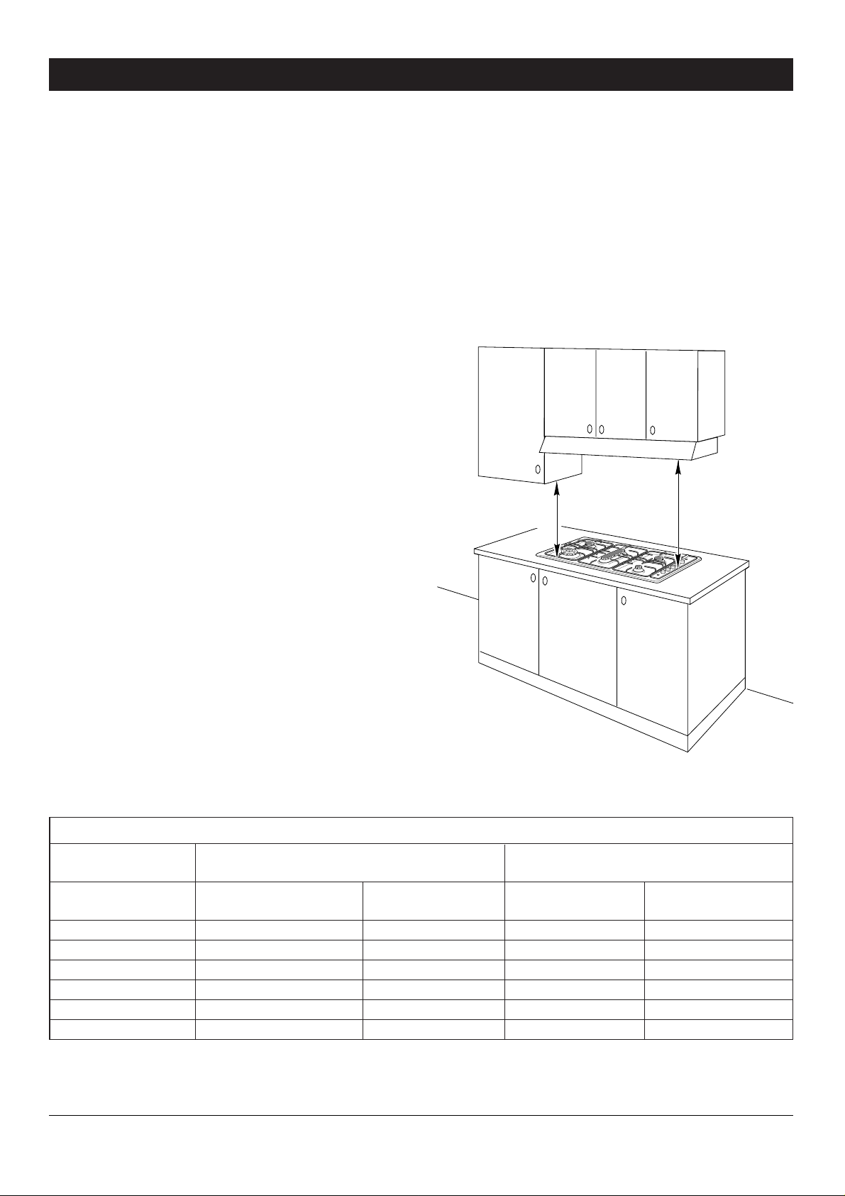
CLEARANCES:
Installation clearances and protection of combustible
surfaces shall comply with section 5.12 of AG 601 - 1995.
Figure 1
650 mm
450 mm
INSTALLATION
Page 4
• 4 •
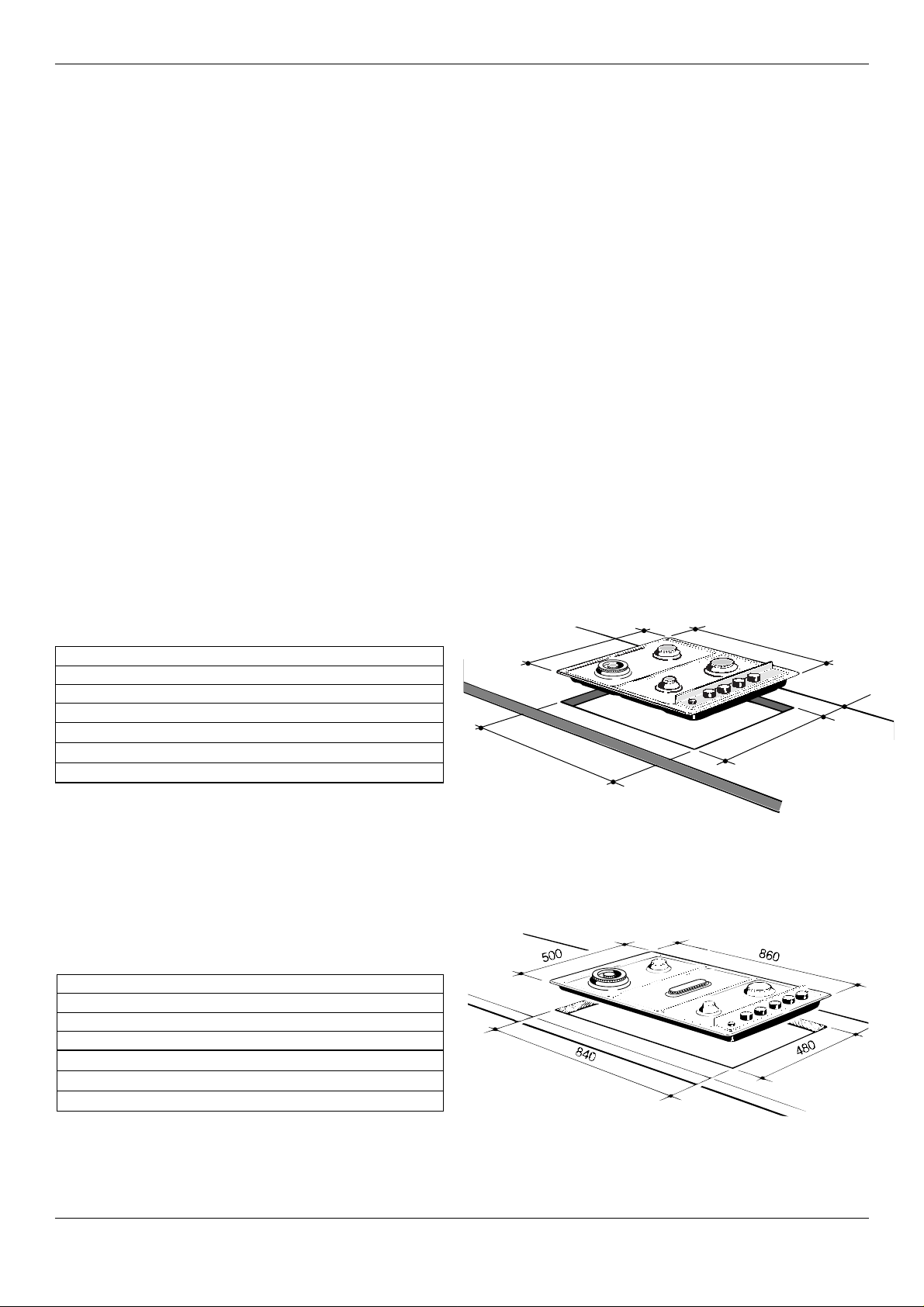
DIMENSIONS (Table 3):
Models: CH35 - CH95S
(Note: Also refer to Figure 3 side)
General Dimensions
Width 860 mm
Depth 500 mm
Depth Below Mounting Surface 30 mm
Cut-out Dimensions
Width 840 mm
Depth 480 mm
Figure 3
General Dimensions
Width 580 mm
Depth 500 mm
Depth Below Mounting Surface 30 mm
Cut-out Dimensions
Width 560 mm
Depth 480 mm
Figure 2
The installation shall comply with the dimensions in
Figures 2 and 3, bearing in mind that:
✓ A minimum clearance of 20 mm has to be kept
between the bottom of the cooking hob and the top
of an appliance or a shelf.
✓ A partition between the base of the hob and the
cupboard below should be fitted 100 mm below the
workbench surface if the cupboard is to be used for
storage.
✓ Overhead clearances - In no case shall the clearance
between the highest part of the hob and a range hood
be less than 600 mm, or for an overhead exhaust fan,
750 mm. Any other downward facing combustible
surface less than 600 mm above the highest part of the
hob shall be protected for the full width and depth of
the cooking surface area in accordance with Clause
5.12.1.2 of AG 601. However, in no case shall this
clearance to any surface be less than 450 mm.
✓ Side clearances - Where the dimension from the
periphery of the nearest burner to any vertical
combustible surface is less than 200 mm, the surface
shall be protected in accordance with Clause 5.12.1.2
of AG 601 to a height of not less than 150 mm above
the hob for the full dimension (width or depth) of the
cooking surface area.
✓ Protection of combustible surfaces - AG 601 Clause
5.12.1.2 specifies that where required protection shall
ensure that the surface temperature of the combustible
surface does not exceed 50 °C above ambient. The
fixing of 5 mm thick ceramic tiles to the surface or
attaching fire resistant material to the surface and
covering with sheet metal with minimum thickness of
0.4 mm would satisfy this requirement.
DIMENSIONS (Table 2):
Models: CH24 - CH25 - CH26
CH84W - CH85S - CH86B
(Note: Also refer to Figure 2 side)
560
500
580
50
480
Page 5

• 5 •
INSTALLATION
(Refer to Figures 4 and 5):
1. Spread out the gasket “C” over the workbench at the
edge of the cut out taking care to overlap the gasket
at the corners.
2. Slot in the cooking hob into the cut out of the
workbench and locate it correctly.
3. Adjust the clamps “A” and tighten the screws “B” until
the hob is firmly secured.
4. Using a sharp tool, trim any excess gasket which
protrudes from the edge of the hob.
5. Assemble the three piece burners. Take care to
properly locate the assembled burner on the burner
base.
B
C
A
Figure 4
20 mm min.
40 mm max.
B
C
A
GAS SUPPLY:
✓ This appliance is suitable for use with Natural Gas or
LPG. (Check the “gas type” sticker attached to the
appliance).
✓ For Natural Gas models the gas supply is connected to
the pressure regulator which is supplied with the
appliance. Adjust the regulator to obtain a test point
pressure of 1 kPa with the two largest burners
operating.
✓ For LPG models connect the gas supply directly to the
appliance inlet connection and ensure that the supply
pressure is regulated to 2.75 kPa.
✓ Do NOT force the “elbow” rotation prior to
loosening the nut.
✓ Do NOT over tighten the nut at the “elbow”.
1. After connecting the gas supply, check the piping and
connections for leaks using a soap and water solution.
The presence of bubbles indicates a leak, tighten or
replace connections as appropriate.
2. Adjust the test point pressure or supply pressure to
the value which is appropriate for the gas type.
3. Turn on the appliance gas controls and light each
burner. Check for a well defined blue flame without
any yellow tipping. If any abnormality is evident then
check that the burner cap is located properly and the
injector nipple is aligned correctly.
4. Check the minimum burner setting by quickly rotating
the gas control knob from the maximum to the
minimum position, the flame must not go out. If
adjustment is required carry out the “minimum burner
setting adjustment" procedure described below.
5. If satisfacfory performance cannot be obtained isolate
the appliance and contact the local gas authority for
advice and assistance.
Figure 5
20 mm min.
40 mm max.
Page 6

• 6 •
INJECTOR REPLACEMENT:
This appliance is suitable for use with Natural Gas or
LPG. (Check the “gas type” sticker attached to the
appliance.) The nominal gas consumption and injector size
details are provided in Table 1 on page 3.
To replace injectors
1. Remove the knobs and ignition push button
2. Unscrew the “A” screw in Figure 6
3. Remove the control panel “B” in Figure 6
4. With a wrench “C” replace the injectors “J” with
those suitable for the gas to be used (see Figure 7).
A
B
Figure 7
Figure 6
C
J
J
MINIMUM BURNER SETTING
ADJUSTMENT:
To regulate the flame follow the instructions below:
• Light the burner
• Set the cock valve to minimum
On gas valves provided with adjustment screw in
the centre of the shaft (fig. 8a):
• Using a screwdriver with max. diameter 3 mm, turn the
screw inside the tap until the correct setting is
obtained.
On gas valves provided with adjustment screw on
the valve body (fig. 8b):
• Turn the screw “A” to the correct setting with a
screwdriver.
Figure 8b
Figure 8a
A
Page 7

• 7 •
ELECTRICAL REQUIREMENTS:
WARNING:
✓ THIS APPLIANCE MUST BE EARTHED.
CAUTION:
✓ Ensure that the power outlet is properly earthed
before connecting the appliance.
✓ Disconnect power before servicing the appliance.
The appliance is provided with a standard 240VAC three
pin plug and power cable (3X0.75 mm2).
The wires in the power cable are coloured in accordance
with the following code: Green/Yellow = Earth, Blue =
Neutral, Brown = Active.
If the colours of the wires in the power cable to the
appliance do not correspond with the coloured markings
identifying the terminals in the junction terminal, proceed
as follows:
1. The wire which is coloured green and yellow must be
connected to the terminal marked E (Earth) or
coloured Green.
2. The wire which is coloured blue must be connected to
the terminal marked N (Neutral) or coloured Black.
3. The wire which is coloured brown must be connected
to the terminal marked L (Live) or A (Active) or
coloured Red.
WIRING DIAGRAM:
IGNITION
MODULE
240 VAC
50 Hz
0.5 VA
DANGER 240 VAC
Ignition
Switch
To Electrodes
A
N
E
CH24 - CH25 - CH26
CH84W - CH85S - CH86B
CH35 - CH95S
Figure 9
Figure 10
REPLACEMENT OF IGNITION
MODULE/ELECTRODES/GAS COCKS:
1. Turn off and disconnect gas supply and electricity.
2. Lift off trivets and burner heads, and pull off igniter
and control knobs.
3. Undo the screws “B” and remove the clamps “A”
shown in Figure 4 and remove the hob.
4. Remove screws securing the top of the hob to the
base pan and lift it off.
5. To replace the electrode, unhook the locking spring
and remove the electrode and cable.
6. To remove the igniter module, disconnect the
electrodes, power and igniter switch wires, undo the
two retaining screws and remove the module.
7. To remove the gas cock undo the two screws which
secure it to the gas manifold. On re-assembly ensure
that the injectors are aligned with the burner venturi.
8. Reassemble in reverse order
9. Check all connections for gas leaks with soapy water
(including gas cocks if they have been removed).
GAS COCK LUBRICATION:
1. Turn off gas supply and disconnect electricity.
2. Remove the knobs and ignition push button
3. Unscrew the “A” screw in Figure 6
4. Remove the control panel “B” in Figure 6
5. Unscrew the two screws on top of the gas cock
6. Lift out the valve cone, clean it with solvent and regrease it with high temperature grease
7. Replace the valve cone, move it around and remove
excess grease. Remove it once again and check that
internal holes or galleries are not blocked.
8. Replace and reassemble in reverse order.
9. Check for gas leaks with soapy water.
Ignition
Switch
A
N
E
DANGER 240 VAC
IGNITION
MODULE
240 VAC
50 Hz
0.5 VA
To Electrodes
Page 8

• 8 •
CAUTION:
✓ This appliance must be used only for the task it has
explicitly been designed for, that is for cooking
foodstuffs. Any other form of usage is to be
considered as inappropriate and therefore dangerous.
Do not use this appliance as a space heater.
✓ Do NOT place combustible materials or products on
this appliance at any time.
Operates right rear burner
Operates left rear burner
Operates middle burner
Operates left front burner
Operates right front burner
Ignition
Semi rapid
burner no. 1
Semi rapid
burner no. 1
Wok
burner
Wok
burner
Fish
warmer
Simmer
burner
Simmer
burner
Semi rapid
burner no. 2
Semi rapid
burner no. 2
Figure 12
CH35 - CH95S
Operates right rear burner
Operates left rear burner
Operates left front burner
Operates right front burner
Ignition
Figure 11
CH24 - CH25 - CH26
CH84W - CH85S - CH86B
✓ Do NOT spray aerosols in the vicinity of this appliance
while it is in use.
✓ Before using for the first time, clean the cooktop with
warm soapy water.
✓ Use the coffee pot support to ensure that small
cooking utensils are stable.
USE and CARE
Page 9

• 9 •
✓ Check that the electricity is switched on to allow
spark ignition.
✓ Make sure that all controls are turned to zero.
✓ The gas flow to the burner is controlled by a knob
operating on a safety tap. You control the flow by
turning the knob indicator to line up with the following
symbols:
symbol ● : Off
symbol : full on (nominal rate)
symbol : reduced rate
✓ To ignite automatically, simply push the required knob
down and turn it to maximum, then press ignition
continuously until the burner lights. When the flame is
lit, you can control the temperature by the knob.
✓ To switch off, turn the knob clockwise until you hear
the safety click.
✓ Note that, if you are using a burner at the minimum
setting, you turn the knob clockwise past the maximum
setting before reaching the off position.
COOKING HINTS FOR GAS HOBS
✓ The burners are different sizes, and can be used in
different ways.
✓ The largest can be used for boiling, to seal meat or
foods that are cooked quickly, and the smallest for
stews and sauces.
✓ Always ensure that you use the correct size of
saucepan.
✓ For fast boiling, make sure the flame just reaches the
edge of the pan. Flames going up the side of the pan
means wasted heat and the contents of the pan will
take longer to boil.
Figure 13
CORRECT USE OF DOUBLE-RING
BURNER
✓ The flat-bottomed pans are to be placed directly onto
the pan-support.
✓ To use the WOK you need to place the proper stand
in order to avoid any faulty operation of the wok
burner.
WRONG
Figure 14
Figure 15
CORRECT
To ignite the burners with flame failure device:
1. Turn the knob counter-clockwise to the “full on” position,
then maintain this pressure
2. Press ignition continuously until the burner lights.
3. Wait for about 10 seconds after the gas burner has been lit
before letting go of the knob (security valve activation
delay)
4. You can control the temperature by the knob.
If the burner flame should go out for same reason, the safety
valve will automatically stop the gas flow.
Page 10

• 10 •
CLEANING AND MAINTENANCE
GENERAL ADVICE
✓ It is advisable to clean when the appliance is cold and
especially when cleaning the enamelled parts.
✓ Avoid leaving alkaline or acidic substances (lemon juice,
vinegar, etc.) on the surfaces.
✓ Avoid using cleaning products with a chlorine or acidic
base.
ENAMELLED PARTS
✓ All of the enamelled parts must be washed only with a
sponge and soapy water or with non-abrasive products.
Dry, preferably, with a soft cloth or chamois.
STAINLESS STEEL
✓ Clean with a suitable product. Always dry fully with a
soft cloth or chamois.
BURNERS AND RACKS
✓ These parts may be removed and washed with suitable
products.
✓ The burners and their caps must be well dried after
cleaning and put back perfectly into their slots. It is
very important to verify the positioning of the burnercaps because a misplacing in their slots can cause
serious damage.
✓ In the appliances with electrical ignition for the
burners, verify that the electrode is always cleaned well
to permit a regular spark.
SERVICE AND MAINTENANCE
If the ignition spark fails to operate or does not light the
gas check the following items before calling the authorized
service agent:
✓ Burner is reassembled and located correctly.
✓ Spark electrode and white ceramic are clean and dry.
✓ 240 VAC power supply is connected.
Contact the local gas utility or the authorized service
agent if:
✓ You can smell gas when all burners are turned on.
✓ The burners do not remain alight at the minimum
marked setting
✓ The burner flame is yellow or emits an unusual odour
Note that a bi-annual inspection of the appliance by an
authorized service agent or your local gas utility will
ensure many years of trouble free operation of your
appliance.
Page 11

• 11 •
WARRANTY AND SERVICE
DOMESTIC WARRANTY - FULL FIVE YEAR WARRANTY
In addition to all statutory rights which you, the Consumer, have under the relevant laws in respect of this appliance,
during the first five years of ownership as the original purchaser of this Kleenmaid appliance, we garantee that any fault
caused by faulty material or workmanship becoming apparent will be rectified free of charge for parts and labour, provided
that all service is performed during normal working hours by Kleenmaid or their designated Agents. Where the appliance
is installed outside the normal servicing area of the above, the Purchaser must pay for the cost of transporting the
appliance to and from the Agent or the Agent’s travelling cost to and from the Purchaser’s home.
COMMERCIAL WARRANTY - ONE YEAR WARRANTY
When this appliance is installed in a commercial application, you, the Consumer, have under the relevant laws in respect
of this appliance, during your first one year of ownership as the original purchaser of the Kleenmaid appliance, we
garantee that any fault caused by faulty material or workmanship becoming apparent, will be rectified free of charge for
parts and labour, provided that all service is performed during normal working hours by Kleenmaid or their designated
Agents. Where the appliance is installed outside the normal servicing area of the above, the Purchaser must pay for the
cost of transporting the appliance to and from the Agent or the Agent’s travelling cost to and from the Purchaser’s home.
WHAT THESE WARRANTIES DO NOT COVER
We are not responsible for any damage or malfunction unless caused by a defect in material or workmanship. This
includes but is not limited to abuse, misuse, improper installation and transportation damage. We are not responsible for
any consequential damages from any malfunction.
WARRANTY DOES NOT COVER REPLACEMENT OF LIGHT GLOBES OR GLASS
BREAKAGE DUE TO IMPACT
In case of fractured glass do not use your appliance.
WARRANTY REGISTRATION
Please complete the enclosed warranty card and post it to us or phone our Customer Call Centre.
SERVICE ASSISTANCE
To assist you when phoning our Customer Call Centre number to arrange a service call please complete the following
details and have them ready when you call.
Model Number:.................................................................................... Date of purchase:.....................................................
Kleenmald Store purchased from:.................................................. Date of installation:..................................................
KLEENMAID CUSTOMER CALL CENTRE
CONTACT NUMBER
1 800 072 144
Page 12

• Ed. 2 - 1101156.1 •
ß8
 Loading...