

Page 1

RANGEHOOD
c o l l e c t i o n
Instructions for Use
and Warranty Details
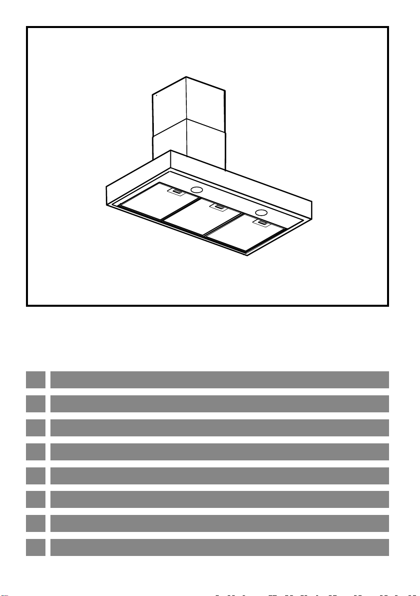
BOX90 - Wallmounted Canopy 900mm
BOX120 - Wallmounted Canopy 1200mm
Page 2
E Montaje y modo de empleo
P Instruções para montagem e utilização
F Prescriptions de montage et mode d’emploi
GB Instruction on mounting and use
D Montage- und Gebrauchsanweisung
I
Istruzioni di montaggio e d’uso
CZ
RU
LI1VBB Ed. 07/02
NÁVOD K MONTÁI A POUITÍ
ИНСТРУКЦИИ ПО УСТАНОВКЕ И ПОЛЬЗОВАНИЮ
Page 3

ongratulations on the purchase of
your new appliance. This
appliance has been designed and
I
C
results, carefully read the instructions on how to
install your new appliance. Correct installation
will avoid delays and unnecessary service calls.
Once installation is complete, read this booklet
carefully and get to know the controls and the
features of your new appliance.
We reserve the right to alter the specifications
with no influence on the operation of the
appliance. This instruction manual cannot be
reason for a claim.
I
manufactured to give you years of
reliable performance. For best
Page 4

10
1
5
6
8
9
B
4
9
9
3
2
9
8
8
1
7
7
Fig. 1 - Abb. 1 -
Obr. 1 - Ðèñ. 1
Page 5
11
14
15
15
12
13
Fig. 2 - Abb. 2 -
16
Obr. 2 - Ðèñ. 2
Page 6
6
f1
3
2
Fig. 3 - Abb. 3 -
4
2
3
Obr. 3 - Ðèñ. 3
1
4
2
5
3
Fig. 4 - Abb. 4 -
f2
Obr. 4 - Ðèñ. 4
Fig. 5 - Abb. 5 -
Obr. 5 - Ðèñ. 5
Fig. 6 - Abb. 6 -
Obr. 6 - Ðèñ. 6
Page 7
E
Instalación - Fig. 1-2
La campana tiene que tener una distancia mínima de los
fuegos de 50 cm en las cocinas eléctricas y de 75 cm en
las cocinas a gas o mixtas.
La campana se suministra dotada de una salida de aire superior B
para la descarga de los humos hacia el exterior (Versión aspirante
- tubo de descarga y abrazaderas de fijación no suministrados).
Si no es posible descargar los humos y los vapores de cocción al
exterior, se puede utilizar la campana en versión filtrante montando
un filtro de carbones activos; de esta manera, los humos y los
vapores se reciclan.
Informaciones preliminares para instalar la campana:
La campana está dotada con tacos de fijación adecuados
a la mayor parte de paredes/techos. De cualquier modo,
conviene consultar a u técnico calificado para tener la
certeza de que los materiales son adecuados a su parede/
techo. La/El parede/techo debe ser lo suficientemente fuerte
para sostener el peso de la campana.
Desconectar la campana interviniendo en el cuadro general
doméstico, en las fases de conexión eléctrica.
Quitar el filtro o los filtros antigrasa.
1. Con un lápiz, trazar una línea en la pared, hasta el techo,
que corresponda a la línea central para facilitar las
operaciones de instalación.
2. Aplicar el esquema de taladrado en la pared: la línea central
vertical impresa en el esquema tiene que coincidir con la línea
central trazada en la pared; además, el borde inferior de la
plantilla de taladrado tiene que coincidir con el borde inferior de
la campana: téngase en cuenta que el lado inferior de la
campana, terminada la instalación, tiene que quedar a 50 cm de
la placa de cocción, si ésta es eléctrica, o a 75 cm si la placa es
de gas o mixta.
3. Apoyar la brida de soporte sobre el esquema de taladrado de
manera que coincida con el rectángulo con trazo discontinuo,
marcar los dos orificios externos y taladrar. Quitar el esquema
de taladrado, poner los 2 tacos de pared y fijar la brida de
soporte de la campana con 2 tornillos de 5x45 mm.
4. Colgar la campana en la brida.
5. Regular la distancia de la campana a la pared.
6. Regular la posición horizontal de la campana.
7. Marcar los 4 orificios para la fijación definitiva de la campana
con un lápiz. Quitar la campana de la brida.
8. Efectuar los orificios (Ø 8 mm) y poner 4 tacos, sujetar la
campana a la brida inferior.
9. Fijar definitivamente la campana a la pared con 4 tornillos de
5x45 mm (ABSOLUTAMENTE NECESARIO).
10. Conectar el tubo para la descarga de los humos (tubo y
abrazaderas no suministrados, se tienen que comprar) al anillo
de conexión ubicado encima de la unidad del motor aspirante.
El otro extremo del tubo tiene que conectarse a un dispositivo
de expulsión de los humos hacia el exterior en caso de uso de
la campana en versión aspirante.
MONTAJE Y MODO DE EMPLEO
Efectuar la conexión eléctrica.
11. Fijar la brida de soporte de la sección inferior de la chimenea con
2 tornillos (uno por lado - la brida inferior se reconoce porque es
más corta que la brida superior) y apoyar la sección inferior de
la chimenea encima de la campana de manera que cubra el
compartimiento del motor aspirante.
12. Tras controlar que la campana quede bien colocada
(véanse también las operaciones 4 y 5), marcar, con
un lápiz, los 2 orificios para fijar la brida, quitar la
chimenea, efectuar los orificios (Ø 8 mm) y poner 2 tacos
de pared.
13. Introducir la sección superior de la chimenea dentro de la
sección inferior y controlar que los lados con los orificios queden
orientados hacia arriba.
Volver a colocar las chimeneas encima de la campana y fijar la
sección inferior a la pared mediante la brida y 2 tornillos.
14. Utilizar la brida superior como plantilla de taladrado y, con un
lápiz, marcar dos orificios en la pared, efectuar los orificios (Ø
8 mm), poner dos tacos de pared y fijar la brida superior.
Téngase en cuenta que la brida se tiene que fijar cerca del
techo, en la vertical de la brida inferior de soporte de las
chimeneas.
15. Fijar la sección superior de la chimenea a la brida con dos
tornillos (uno por lado).
16. Fijar la sección inferior de la chimenea a la campana
utilizando 7 tornillos. Volver a montar la pantalla protectora
interna.
Montar el filtro/los filtros antigrasa y controlar que la campana
funcione perfectamente.
Conexión eléctrica
La corriente de la red debe corresponder a la corriente señalada en
la etiqueta de las características situada en el interior de la campana.
Si contiene un enchufe conecte la campana a una toma de corriente
conforme a las normas vigentes situada en una zona accesible. Si
contiene un enchufe(conexión directa a la red, aplique un interruptor
bipolar a norma con una distancia de los contactos en abertura no
inferior a 3 mm ( accesible.).
Consulte tambien los dibujos de las primeras páginas con las referencias alfabéticas del texto explicativo.
Aténgase estrictamente a las instrucciones del presente manual. Se declina cada responsabilidad por eventuales inconvenientes, daños o incendios
provocados al aparato originados por la inobservancia de las instrucciones colocadas en este manual.
Page 8
E
Descripción de la campana- Fig. 3
1 Cuadro de control
2 Filtro antigrasa
3 Manija de desenganche del filtro antigrasa
4 Lámpara halógena
5 Protección contra vapores
6 Chimenea telescópica
Funcionamiento
Descripción del cuadro de control y funcionamiento
de la campana
MONTAJE Y MODO DE EMPLEO
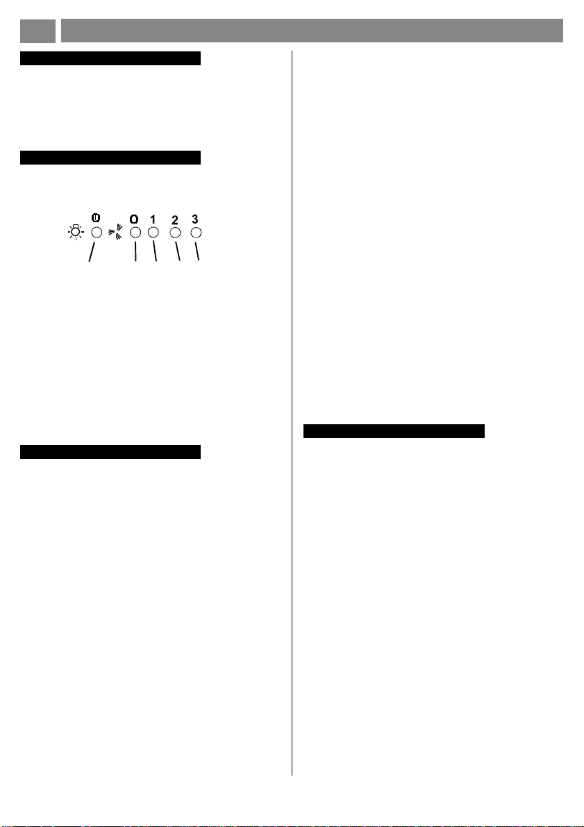
abcde
Filtro al carbón activo (solamente para la versión
filtrante)
Sirve para disolver los vahos y olores que emanan las
comidas durante su cocción.
El filtro al carbón activo no debe ser lavado.
El filtro de carbón tiene que ser reemplazado cada 4 meses
cuando la campana se usa normalmente.
Para montar el filtro de carbón - Fig. 5:
1. Desenchufe la campana o quite la corriente.
2. Saque el filtro antigrasa.
3. Coloque filtro al carbón activo fijándolo mediante los dos
tornillos que vienen en correspondiente dotación.
4. Vuelva a colocar el filtro antigrasa.
Para substituir el filtro de carbón - Fig. 5:
1. Desenchufe la campana o quite la corriente.
2. Saque el filtro antigrasa.
3. Saque el viejo filtro al carbón activo y substitúyalo con
uno nuevo.
4. Vuelva a colocar el filtro antigrasa.
a. Botón ON/OFF luces.
b. Botón OFF/ON aspiración
c. Botón seleccción potencia mínima.
d. Botón selección potencia de aspiración media.
e. Botón selección potencia de aspiración máxima.
Usar la potencia de aspiraciòn mayor en caso de particular
concentraciòn de vapores de cocina. Aconcejamos de
encender la aspiraciòn 5 minutos antes de iniciar a cocinar
y dejarla en funciòn por otros 15 minutos aproximadamente.
Mantenimiento
Antes de cualquier trabajo de mantenimiento desconectar la
campana de la corriente.
Limpieza
La campana debe ser limpiada con frecuencia tanto
externamente como internamente. Para limpiarla use un
paño empapado de alcohol desnaturalizado y detergentes
líquidos neutros. Evite el uso de productos que contengan
abrasivos.
Atención:
Si no se respetan las normas de limpieza de la campana
y del cambio y limpieza de los filtros puede haber riesgo de
incendio. Rogamos se atenga a las instrucciones indicadas.
Filtro antigrasa
Debe limpiarse una vez al mes con detergentes no agresivos,
manualmente o bien en lavavajillas a bajas temperaturas
y con ciclo breve.
Con el lavado en el lavavajilla el filtro antigrasa metálico
puede desteñirse pero sus características de filtrado no
cambian absolutamente.
Para desmontar el filtro antigrasa, tire de la manilla de
desenganche con muelle primero hacia atrás (f1) y después
hacia abajo (f2). (Fig 4).
Sustitución de la lámpara - Fig. 6
Utilice un destornillador u otro utensilio para hacer palanca,
extraiga el plafón. Cambie la lámpara estropeada. Utilice
solamente lámparas halógenas de 20W máx, teniendo
cuidado de no tocarlas con las manos.
Vuelva a montar el plafón (sujeción a resorte).
Si la iluminación no funciona, antes de llamar al
servicio de asistencia técnica, controlar que las
lámparas estén bien montadas en su sede.
Advertencias
No use nunca la campana sin haber montado correctamente
la rejilla. El aire aspirado no debe ser canalizado en un
conducto usado para la descarga de humos de aparatos
alimentados con energía que no sea eléctrica.Hay que
realizar anteriormente una adecuada aireación del local
cuando se usen al mismo tiempo la campana y los aparatos
alimentados con otra energía que no sea eléctrica. Está
rigurosamente prohibido cocinar alimentos a la llama debajo
de la campana. El empleo de la llama libre daña los filtros
y puede provocar incendios, por lo tanto debe evitarse en
cualquier caso. Cuando se fríen los alimentos se debe tener
cuidado de que el aceite no se caliente en exceso y se
incendie. Para las medidas técnicas y de seguridad que
haya que adoptar para la descarga de los humos aténgase
rigurosamente a lo que diga el reglamento de las autoridades
locales competentes.
Consulte tambien los dibujos de las primeras páginas con las referencias alfabéticas del texto explicativo.
Aténgase estrictamente a las instrucciones del presente manual. Se declina cada responsabilidad por eventuales inconvenientes, daños o incendios
provocados al aparato originados por la inobservancia de las instrucciones colocadas en este manual.
Page 9

P
Instalação - Fig. 1-2
A coifa deve ficar a uma distância mínima do plano de
cozimento de 50 cm, no caso de cozinhas elétricas e de 75
cm, no caso de cozinhas a gás ou mistas.
O exaustor é fornecido com uma saída de ar superior B para a
descarga da fumaça ao exterior (Versão aspirante- tubo de descarga
e braçadeiras de fixação não fornecidos).
Se não for possível descarregar a fumaça e os vapores de cozedura
para o exterior, o exaustor poderá ser utilizado na versão filtrante,
desde que se monte um filtro de carvão activo. Nesta configuração,
a fumaça e os vapores são reciclados.
Informações preliminares para a instalação do
exaustor:
O fornecimento do exaustor inclui buchas de fixação,
adequadas para a maior parte dos tectos/paredes. Contudo,
é necessário contactar um técnico habilitado para verificar
a idoneidade dos materiais segundo o tipo de tecto/parede.
O tecto/parede deve ser suficientemente robusto para
suportar o peso do exaustor.
Desligue a rede eléctrica no quadro geral doméstico nas
fases da ligação eléctrica.
Tire os filtros de gorduras.
1. Com um lápis, trace uma linha na parede, até ao tecto,
2. Aplique o esquema de perfuração na parede: a linha vertical no
3. Apoie a peça de suporte no esquema de perfuração fazendo
4. Pendure o exaustor no suporte.
5. Regule a distância entre o exaustor e a parede.
6. Regule o nivelamento horizontal do exaustor.
7. Marque os 4 furos para a fixação definitiva do exaustor com um
8. Faça os furos (Ø 8 mm) e introduza 4 buchas de expansão.
9. Fixe o exaustor definitivamente na parede com 4 parafusos
10. Faça a ligação de um tubo (o tubo e as braçadeiras não são
INSTRUÇÕES PARA MONTAGEM E UTILIZAÇÃO
correspondente ao centro do exaustor: isto irá facilitar as
operações de instalação.
centro, impressa no esquema de perfuração, deverá coincidir
com a linha central traçada na parede; além disso, a borda
inferior do esquema de perfuração corresponde à borda inferior
do exaustor. Lembre-se de que o lado inferior do aparelho,
concluída a instalação, deve ficar afastado pelo menos 50 cm
da placa de cozedura se esta possuir discos eléctricos e 75 cm
se os queimadores forem a gás ou mistos.
com que coincida com o rectângulo traçado. Marque os dois
furos exteriores e faça os furos. Tire o esquema de perfuração,
introduza 2 buchas de expansão na parede e fixe a peça de
suporte do exaustor com 2 parafusos 5x45 mm.
lápis. Tire o exaustor do suporte.
Prenda o exaustor no suporte inferior.
5x45 mm (ABSOLUTAMENTE NECESSÁRIO).
fornecidos, devendo ser comprados) para a descarga da fumaça
no anel de conexão posto acima da unidade do motor aspirante.
A outra extremidade do tubo deverá ser ligada a um dispositivo
de expulsão da fumaça para o exterior, caso o exaustor seja
utilizado na versão aspirante.
Faça a ligação eléctrica.
11. Fixe a peça de suporte da secção inferior da chaminé
com 2 parafusos (um de cada lado – reconhece-se a
peça de suporte inferior porque é mais curta do que a
superior) e apoie a secção inferior da chaminé em cima
do exaustor, cobrindo o compartimento do motor de
aspiração.
12. Tendo controlado o perfeito nivelamento do exaustor (ver
também as operações 4 e 5), marque com um lápis os 2 furos
para a fixação do suporte. Tire a chaminé, faça os furos
(Ø 8 mm) e introduza 2 buchas de fixação na parede.
13. Enfie a secção superior da chaminé dentro da secção
inferior, verificando se os lados com os furos estão
virados para cima.
Recoloque as secções da chaminé em cima do exaustor e fixe
a secção inferior na parede, por intermédio do suporte, com 2
parafusos.
14. Fixe o suporte superior na vertical da peça inferior de suporte
das secções da chaminé, perto do tecto. Utilize o próprio
suporte como esquema de perfuração: marque dois furos com
um lápis, faça os furos (Ø 8 mm) e introduza duas buchas de
fixação na parede.
15. Fixe a secção superior da chaminé no suporte usando dois
parafusos (um de cada lado).
16. Fixe a secção inferior da chaminé no exaustor utilizando
7 parafusos. Reinstale o painel de protecção interno.
Reinstale os filtros de gorduras e controle o funcionamento
perfeito do exaustor.
Conexão elétrica
A tensão de rede deve corresponder à tensão indicada na etiqueta
de características situada na parte interna da coifa. Se completo de
plug conectar a coifa a uma tomada, conforme as normas vigentes,
posta em zona acessível.
Se não completo de plug (conexão direta à rede) aplicar um
interruptor bipolar conforme normas com uma distância entre
contactos em abertura não inferior a 3mm (acessível).
Consultar também os desenhos nas primeiras páginas com as referências alfabéticas indicadas no texto explicativo.
Ater-se especificamente às instruções indicadas neste manual. Declina-se qualquer responsabilidade por eventuais inconvenientes, danos ou
incêndios provocados ao aparelho, derivantes da inobservância das instruções indicadas neste manual.
Page 10

P
Descrição do exaustor – Fig. 3
1 Painel de controlo
2 Filtro antigordura
3 Puxador para libertar o filtro antigordura
4 Lâmpada de halogéneos
5 Protecção contra os vapores
6 Chaminé telescópica
Funcionamento
Descrição do painel de controlo e funcionamento do
exaustor
INSTRUÇÕES PARA MONTAGEM E UTILIZAÇÃO
abcde
a. botão ON/OFF luzes
b. botão OFF aspiração
c. botão de seleção da potência mínima
d. botão de seleção da potência de aspiração média
e. botão de seleção da potência de aspiração máxima
Usar a potência de aspiração no caso de uma maior
concentração de vapores de cozimento. Aconselhamos
ligar a aspiração 5 minutos antes de iniciar a cozinhar e de
deixá-la em funcionamento por aproximadamente 15 minutos
após o término do cozimento.
Filtro de carvão activo (só para a versão filtrante)
Serve para eliminar os cheiros e vapores, durante a
cozedura.
Serve para eliminar os cheiros e vapores, durante a
cozedura.
O filtro de carvão activo não é lavável.
O filtro de carvão activo deve ser substituído cada 4 meses,
em condições de utilização norma.
Para montar o filtro de carvão activo- Fig. 5:
1. Tirar a ficha ou desligar a corrente.
2. Tirar o filtro antigordura.
3. Montar o filtro de carvão activo fixando-o com os dois
parafusos fornecidos com o aparelho.
4. Recolocar o filtro antigordura.
Para substituir o filtro de carvão activo- Fig. 5:
1. Tirar a ficha ou desligar a corrente.
2. Tirar o filtro antigordura.
3. Retire o filtro de carvão activo velho e substitua-o.
4. Recolocar o filtro antigordura.
Substituição das lâmpadas - Fig. 6
Utilizar uma chave de fenda ou outra ferramenta adequada
para fazer alavanca, extrair a lâmpada embutida. Substituir
a lâmpada danificada. Utilizar apenas lâmpadas halógenas
de 20W máx, tendo o cuidado de não tocá-las com as mãos.
Remontar a lâmpada embutida (fixação de engate).
Se a iluminação não funcionar, verifique se as lâmpadas
foram correctamente instaladas na sua sede antes de
chamar a assistência técnica.
Manutenção
Antes de qualquer trabalho de manutenção desconectar a
coifa da rede elétrica.
Limpeza
A coifa deve ser limpa freqüentemente.
Para a limpeza utilizar um pano umedecido em detergentes
líquidos neutros.
Evitar o uso de produtos que contenham substâncias
abrasivas.
Atenção
A inobservância das normas de limpeza da coifa e da
substituição e limpeza dos filtros comporta riscos de
incêndio. Recomendamos seguir atentamente as
instrucções e os avisos.
Filtro antigrasa
Debe limpiarse una vez al mes con detergentes no agresivos,
manualmente o bien en lavavajillas a bajas temperaturas
y con ciclo breve.
Con el lavado en el lavavajilla el filtro antigrasa metálico
puede desteñirse pero sus características de filtrado no
cambian absolutamente.
Para desmontar o filtro anti-gorduras, puxar a alça de
desengate de mola, antes para trás (f1) em seguida para
baixo (f2). Fig. 4.
Consultar também os desenhos nas primeiras páginas com as referências alfabéticas indicadas no texto explicativo.
Ater-se especificamente às instruções indicadas neste manual. Declina-se qualquer responsabilidade por eventuais inconvenientes, danos ou
incêndios provocados ao aparelho, derivantes da inobservância das instruções indicadas neste manual.
Advertências
Nunca utilizar a coifa sem a grelha corretamente montada!
O ar aspirado não deve ser transportado em um duto usado
para a descarga de fumos de aparelhos alimentados por
energia que não seja elétrica. Deve ser sempre prevista
uma aeração do local quando uma coifa e aparelhos
alimentados com energia diferente da elétrica são usados
contemporaneamente. É severamente proibido cozinhar
alimentos diretamente na chama sob a coifa. O emprego da
chama livre é danoso aos filtros e pode ocasionar incêndios,
portanto deve ser sempre evitado. A fritura deve ser feita
sob controle de maneira a evitar que o óleo superaquecido
se incendeie. Para as medidas técnicas e de segurança a
serem adotadas para a descarga dos fumos ater-se a quanto
previsto pelos regulamentos das autoridades competentes
locais.
Page 11

PRESCRIPTIONS DE MONTAGE ET MODE D’EMPLOI
F
Installation - Fig. 1-2
Si vous possédez un plan de cuisson entièrement électrique,
la hotte doit etre installée a une distance de 50 cm , de 75
cm dans le cas d’un plan de cuisson mixte ou a gaz.
La hotte est équipée d’une sortie de l’air supérieure B pour l’évacuation
des fumées vers l’extérieur (Version aspirante – tuyau d’évacuation
et colliers de fixation non fournis).
Dans l’éventualité où il ne serait pas possible d’évacuer les fumées
et les vapeurs de cuisson vers l’extérieur, il est possible d’utiliser la
hotte dans la Version filtrante, en effectuant le montage d’un filtre
à charbon actif, les fumées et les vapeurs sont recyclées.
Informations préliminaires pour l’installation de la
hotte:
Débrancher la hotte, en intervenant sur le tableau électrique
général domestique, pendant les phases de branchement
électrique.
La hotte est équipée de chevilles de fixation convenant à la
plupart des parois/plafonds. Il est cependant nécessaire de
s’adresser à un technicien qualifié afin de s’assurer que le
matériel est approprié au type de paroi/plafond. Le paroi/
plafond doit être suffisamment solide pour supporter le poids
de la hotte. Retirer le/s filtre/s anti-graisse.
1. Au moyen d’un crayon, tracer une ligne sur la paroi, jusqu’au
plafond, en correspondance de la ligne médiane afin de faciliter
les opérations d’installation.
2. Appliquer le schéma de perçage contre la paroi: la ligne médiane
verticale imprimée sur le schéma de perçage devra correspondre
à la ligne médiane dessinée sur le mur. Le bord inférieur du
schéma de perçage devra également correspondre au bord
inférieur de la hotte: il faut tenir compte du fait que, après avoir
terminé l’installation, le côté inférieur de la hotte doit se trouver
à 50 cm. au moins de distance par rapport au plan de cuisson,
en cas de fourneaux électriques, et à 75 cm. en cas de
fourneaux à gaz ou mixtes.
3. Poser la bride de support sur le schéma de perçage, en le faisant
coïncider avec le rectangle hachuré, marquer les deux trous
externes puis percer les trous, retirer le schéma de perçage,
insérer 2 chevilles pour le mur et fixer la bride de support de la
hotte à l’aide de 2 vis de 5x45 mm.
4. Suspendre la hotte sur la bride.
5. Régler la distance de la hotte par rapport à la paroi.
6. Régler la position horizontale de la hotte.
7. Marquer à l’aide d’un crayon les 4 trous pour la fixation définitive
de la hotte. Retirer la hotte de la bride.
8. Percer les trous (Ø 8 mm), insérer les 4 chevilles, insérer 4
chevilles pour le mur. Accrocher la hotte sur la bride inférieure.
9. Fixer définitivement la hotte contre la paroi à l’aide de 2 vis de
5x45 mm. (ABSOLUMENT NECESSAIRE).
10. Effectuer la connexion entre le tuyau (tuyau et colliers de fixation
non fournis, à acheter séparément) pour l’évacuation des
fumées et la bague de connexion qui se trouve au-dessus de
l’unité moteur d’aspiration.
L’autre extrémité du tuyau devra être connectée à un dispositif
d’évacuation des fumées vers l’extérieur, en cas d’emploi de la
hotte dans la version aspirante.
11. Fixer la bride de support de la section inférieure de la
cheminée à l’aide de deux vis (une pour chaque côté
– on peut facilement reconnaître la bride inférieure ; étant
donné qu’elle est plus courte par rapport à la bride
supérieure), poser la section inférieure de la cheminée
sur la hotte pour recouvrir le logement du moteur
d’aspiration.
12. Après avoir vérifié que la hotte soit parfaitement alignée (voir
également opérations 4 et 5), marquer les deux trous pour la
fixation de la hotte à l’aide d’un crayon, retirer la cheminée,
percer les trous (Ø 8 mm.) et introduire 2 goujons muraux.
13. Enfiler la section supérieure de la cheminée dans la section
inférieure, veiller à ce que les côtés avec les trous soient
orientés vers le haut.
Repositionner les cheminées sur la hotte, puis fixer la section
Inférieure contre la paroir avec deux vis, au moyen de la bride.
14. Sur la verticale de la bride inférieure de support des cheminées,
à proximité du plafond, fixer la bride supérieure, utiliser ladite
bride en tant que schéma de perçage, marquer les deux trous
à l’aide d’un crayon, percer les trous (Ø 8 mm.), insérer deux
goujons muraux.
15. Fixer la section supérieure de la cheminée contre la bride à
l’aide de deux vis (une de chaque côté).
16. Fixer la section inférieure de la cheminée sur la hotte au
moyen de 7 vis. Remonter l’écran de protection interne.
Remonter les filtres anti-graisse, puis contrôler le fonctionnement
parfait de la hotte.
Branchement électrique
La tension du réseau doit correspondre à la tension indiquée sur
l’étiquette des caractéristiques située dans la hotte. Si la hotte est
fournie avec une fiche, la raccorder à une prise accessible conforme
aux normes en vigueur. Si la hotte est fournie sans fiche ( branchement
direct sur le réseau), la raccorder à un interrupteur bipolaire normalisé
ayant une distance des contacts supérieure à 3 mm (accessible).
Consulter les dessins de la première page avec les références alphabétiques que l’on retrouvera dans le texte explicatif.
Suivre strictement les instructions de cette notice. Le constructeur décline toute responsabilité pour tous les inconvenients, dommages ou incendies
provoquès à l’appareil et dus à la non observation des instructions de la présente notice.
Page 12

PRESCRIPTIONS DE MONTAGE ET MODE D’EMPLOI
F
Description de la hotte – Fig. 3
1 Panneau de contrôle
2 Filtre anti-graisse
3 Poignée de décrochage du filtre anti-graisse
4 Lampe halogène
5 Écran vapeurs
6 Cheminée télescopique
Fonctionnement
Description du panneau de contrôle et fonctionnement
de la hotte
abcde
a.touche ON/OFF éclairage
b.touche OFF aspiration
c.touche sélection puissance minimum
d.touche selection puissance d’aspriration moyenne
e.touche selection puissance d’aspiration maximum
Utiliser la puissance d’aspiration maximum en cas de
concentration très importante des vapeurs de cuisson. Nous
conseillons d’allumer le dispositif d’aspiration 5 minutes
avant de commencer la cuisson et de le faire fonctionner
encore pendant 15 minutes environ après avoir terminé la
cuisson.
Entretien
Veillez a débrancher la hotte du réseau electrique avant toute
intervention sur celle- ci.
Nettoyage
La hotte doit etre regulièrement nettoyée à l’intérieur et à
l’extérieur.
Pour le nettoyage, utiliser un chiffon humide imbibé d’alcool
dénaturé ou de détergents liquides neutres. Eviter d’utiliser
des produits abrasifs.
Attention:
Le non respect des règles de nettoyage de la hotte, de la
substitution et du nettoyage des filtres comporte des risques
d’incendie.
Nous recommandons donc vivement de respecter ces
instructions.
Filtre anti-gras
Le filtre doit être nettoyé une fois par mois, avec des
détergents non agressifs, à la main ou dans le lave-vaisselle
à faibles températures et cycle rapide.
Le lavage du filtre anti-graisse métallique au lave-vaisselle
peut en provoquer la décoloration.
Toutefois, les caractéristiques de filtrage ne seront en aucun
cas modifiées.
Pour démonter le filtre à graisses, tirer la poignée de
décrochage à ressort d’abord en arrière (f1) ensuite vers le
bas (f2). Fig. 4.
Consulter les dessins de la première page avec les références alphabétiques que l’on retrouvera dans le texte explicatif.
Suivre strictement les instructions de cette notice. Le constructeur décline toute responsabilité pour tous les inconvenients, dommages ou incendies
provoquès à l’appareil et dus à la non observation des instructions de la présente notice.
Filtre à charbon actif (uniquement pour version
recyclage)
Retient les odeurs désagréables de cuisson.
Il ne faut jamais laver le filtre à charbon actif.
Le filtre à charbon actif doit être remplacé tous les 4 mois dans
des conditions d’utilisation normale.
Pour monter le filtre à charbon actif - Fig. 5:
1. Débrancher la fiche de la hotte ou couper le courant.
2. Enlever le filtre anti-grais.
3. Montez le filtre à charbon actif en le fixant à l’aide des
deux vis correspondantes fournies avec l’appareil.
4. Remettre le filtre anti-grais.
Pour remplacer le filtre à charbon actif - Fig. 5:
1. Débrancher la fiche de la hotte ou couper le courant.
2. Enlever le filtre anti-grais.
3. Enlever le filtre à charbon actif périmé et le remplacer par
un nouveau.
4. Remettre le filtre anti-grais.
Remplacement des lampes – Fig. 6.
Utiliser un tournevis à découpe ou autre ustensile adéquat
pour soulever et extraire la plafonière. Remplacer la lampes
abîmée. Utiliser uniquement des lampes halogènes de 20
W max, en ayant la bonne intention de ne pas les toucher
avec les mains.
Remonter la plafonière (fixation à cran).
Dans l’éventualité où l’éclairage ne devait pas
fonctionner, vérifier si les lampes ont été introduites
correctement dans leur logement, avant de contacter
le service après-vente.
Attention
Ne jamais utiliser la hotte sans avoir installé correctement
la grille! L’air aspiré ne doit pas etre expulsé dans un conduit
utilisé pour l’échappement des fumées d’appareils alimentés
avec une énergie autre que l’énergie électrique. Il faut prévoir
une bonne aération du local lorsque l’on utilise simultanément
une hotte et des appareils alimentés avec une autre énergie
que l’electricité. Il est strictement défendu de faire flamber des
aliments sous la hotte. Toute flamme sous la hotte peut
endommager les filtres et causer un incendie. La friture doit
etre surveillée pour éviter que l’huile surchauffée ne
s’enflamme. Pour des raisons techniques et de sécurité
veuillez suivre scrupuleusement les réglementations locales
relatives à l’évacuation des fumées.
Page 13

GB
INSTRUCTION ON MOUNTING AND USE
Installation - Fig. 1-2
The cooker hood must be placed at a minimum distance of
50 cm from the cooking plane for electric cookers and 75cm
for gas or mixed cookers.
The hood is equipped with a top air outlet B for discharge of fumes
to the outside (Ducting version – exhaust pipe and pipe fixing
clamps not provided).
Should it not be possible to discharge cooking fumes and vapour to
the outside, the hood can be used in the filter version, fitting an
activated carbon filter, fumes and vapours are recycled.
Preliminary information for installation of the hood:
Disconnect the hood during electrical connection, by turning
the home mains switch off.
Expansion wall plugs are provided to secure the hood to
most types of walls/ceilings. However, a qualified technician
must verify suitability of the materials in accordance with the
type of wall/ceiling. The wall/ceiling must be strong enough
to take the weight of the hood.
Do not tile, grout or silicone this appliance to the wall.
Surface mounting only.
Remove the grease filter/s.
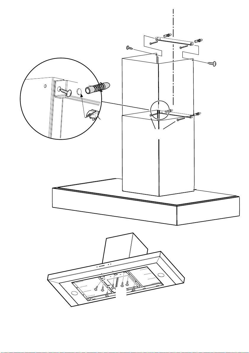
1. Using a pencil, draw a line on the wall, extending up to
the ceiling, to mark the centre. This will facilitate
installation.
2. Rest the drilling template against the wall: the vertical centre line
printed on the drilling template must correspond to the centre
line drawn on the wall, and the bottom edge of the drilling
template must correspond to the bottom edge of the hood: bear
in mind that, when installation is complete, the underside of the
hood must be at least 50 cm above the cooker top in the case
of electric cookers, and at least 75 cm above the cooker top in
the case of gas or mixed cookers.
3. Rest the support bracket on the drilling template so that it
coincides with the dotted rectangle, mark the two outer holes
and drill them, remove the drilling template, insert 2 wall plugs
and fix the hood support bracket into place using two 5x45mm
screws.
4. Hang the hood on the bracket.
5. Adjust the distance of the hood from the wall.
6. Adjust the horizontal position of the hood.
7. Mark the 4 holes to be used for final fixing of the hood. Remove
the hood from the bracket.
8. Dril the holes (Ø8mm), insert 4 wall plugs. Insert 4 wall plugs.
Hook the hood onto the bottom bracket.
9. Fix the hood into its final position on the wall using 2 5x45mm
screws (ABSOLUTELY ESSENTIAL).
10. Connect a pipe (pipe and pipe clamps not provided, to be
purchased separately) for discharge of fumes to the connection
ring located over the suction motor unit.
If the hood is to be used in ducting version, the other end of the
pipe must be connected to a device expelling the fumes to the
outside. Make the electrical connections.
11. Fix the bracket supporting the bottom section of the
chimney using 2 screws (one on each side – the bottom
bracket can be recognised because it is shorter than the
top bracket), rest the bottom section of the chimney over
the hood so that it covers the suction motor compartment.
12. After checking that the hood is perfectly positioned (see also
operations 4 and 5), use a pencil to mark the 2 holes used to fix
the bracket, remove the chimney, drill the holes (Ø 8 mm) and
insert 2 wall plugs.
13. Thread the top section of the chimney into the bottom
section, checking that the sides with the holes face
upwards.
Position the chimney sections over the hood once more, and
fasten the bottom section to the wall, through the bracket, using
2 screws.
14. Fix the top bracket on the vertical line of the bottom chimney
support bracket, close to the ceiling; using the bracket itself as
a boring template, use a pencil to mark two holes, drill them (Ø
8 mm), then insert two wall plugs.
15. Fix the top section of the chimney to the bracket using two
screws (one on each side).
16. Fix the bottom section of the chimney to the hood using
7 screws. Replace the protective internal screen.
Refit the grease filter/s and check that the hood is operating
correctly.
Electrical connection
The electrical tension must correspond to the tension noted on the
label placed inside the cooker hood. Connect the electrical plug,
where provided, to the an easily accessible outlet in conformity with
local standards in force.
Where an electrical plug is not provided (for direct connection to
electrical network) place a standards approved bipolar switch with
an aperture distance of not less than 3mm (accessible) from the
contacts.
Consult the designs in the front pages referenced in the text by alphabet letters. Closely follow the instructions set out in this manual. All responsibility,
for any eventual inconveniences, damages or fires caused by not complying with the instructions in this manual, is declined.
Page 14

GB
INSTRUCTION ON MOUNTING AND USE
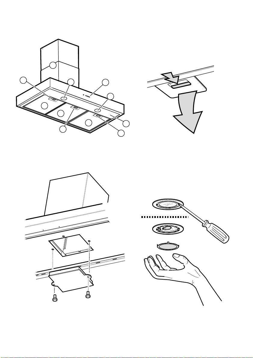
Description of the hood - Fig. 3
1 Control panel
2 Grease filter
3 Grease filter release handle
4 Halogen lamp
5 Vapour catcher
6 Telescopic chimney
Operation
Description of control panel and hood operation
abcde
a. on/off light switch
b. off aspiration switch
c. minimum power selection aspiration switch
d. medium power selection aspiration switch
e. maximum power selection aspiration switch
Use the high suction speed in cases of concentrated kitchen
vapours. It is recommended that the cooker hood suction
is switched on for 5 minutes prior to cooking and to leave
in operation during cooking and for another 15 minutes
approximately after terminating cooking.
Maintenance
Prior to any maintenance operation ensure that the cooker
hood is disconnected from the power supply.
Cleaning
The cooker hood should be cleaned regularly internally and
externally.
For cleaning use a cloth moistened with denatured alcohol
or neutral liquid detergents. Avoid abrasive detergents.
Warning:
Failure to carry out the basic standards of the cleaning
of the cooker hood and replacement of the filters may
cause fire risks. Therefore we recommend oserving these
instructions.
Grease filter
This must be cleaned once a month using non aggressive
detergents, either by hand or in the dish-washer, which must
be set to a low temperature and a short cycle.
When washed in a dish-washer, the grease filter may
discolour slightly, but this does not affect its filtering capacity.
Pull the spring release handle backwards firstly (f1) , then
downwards (f2) in order to dismantle the grease filter. Fig.4.
Charcoal filter (filter version only)
It absorbs unpleasant odors caused by cooking.
The charcoal filter must never be washed.
The charcoal filter should be replaced every 4 months under
normal use.
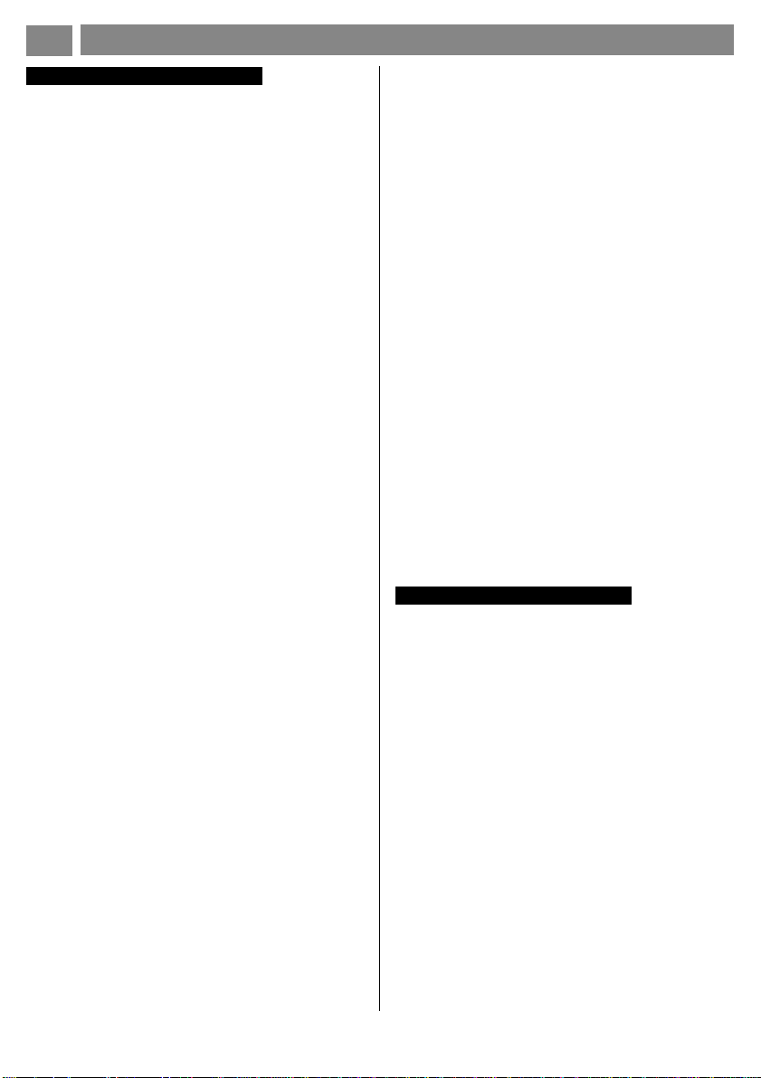
To fit the charcoal filter - Fig. 5:
1. Disconnect the hood from the electricity.
2. Remove the grease filters.
3. Fit the charcoal filter and fix it to the body of the hood with
two supplied screws
4. Put the grease filter back into place.
To replace the charcoal filter - Fig. 5:
1. Disconnect the hood from the electricity.
2. Remove the grease filters.
3. Remove the old charcoal filter and replace it.
4. Put the grease filter back into place.
Replacing lamps - Fig. 6
Use a one-edged screwdriver or any other appropriate tool
to lift and remove the overhead light fixture. Replace the
damaged lamp. Use only halogenous lamps of a maximum
of 20W, avoiding contact with hands. Return the light fixture
to its position (snap fastening).
If the lights do not work, make sure that the lamps are
fitted properly into their housings before you call for
technical assistance.
Caution
This appliance is designed to be operated by adults. Children
should not be allowed to tamper with the controls or play with
the appliance.
Do not use the cooker hood where the grill is not correctly
fixed! The suctioned air must not be conveyed in the same
channel used for fumes discharged by appliances powered
by other than electricity. The environment must always be
adequately aerated when the cooker hood and other
appliances powered by other than electricity are used at the
same time. Flambé cooking with a cooker hood is
prohibited. The use of a free flame is damaging to the filters
and may cause fire accidents, therefore free flame cooking
must be avoided. Frying of foods must be kept under close
control in order to avoid overheated oil catching fire. Carry
out fumes discharging in accordance with the regulations in
force by local laws for safety and technical restrictions.
Consult the designs in the front pages referenced in the text by alphabet letters. Closely follow the instructions set out in this manual. All responsibility,
for any eventual inconveniences, damages or fires caused by not complying with the instructions in this manual, is declined.
Page 15

D
Installierung - Abb. 1-2
Die Küchenhaube muss in einem Abstand von mindestens
50 cm über einem Elektroherd und von mindestens 75 cm
über einem Gasherd oder kombinierten Herd angebracht
werden.
Die Haube verfügt über einen oberen Luftaustritt B zum Ableiten der
Küchengerüche nach außen (Abluftbetrieb- Abluftrohr und
Rohrschellen werden nicht geliefert).
Ist eine Ableitung von Rauch und Kochdämpfen ins Freie nicht
möglich, kann die Haube mit Umluftbetrieb arbeiten; in diesem Fall
muss ein Aktivkohlefilter montiert werden; auf diese Weise wird die
Luft durch das obere Gitter H mit Hilfe eines Abluftrohres, das an den
oberen Luftaustritt B angeschlossen ist, und eines Anschlussrings
am Umleitgitter F (Abluftrohr und Rohrschellen werden nicht geliefert)
rückgeführt.
Einleitende Informationen zur Installation der
Dunstabzugshaube:
Vor dem Anschluss des Gerätes die Haube mit Hilfe der
Hauptschalttafel der Wohnung stromlos setzen.
Die Abzugshaube ist mit Dübeln ausgestattet, die für die
meisten Wände/Decken geeignet sind. Trotzdem sollte ein
qualifizierter Techniker hinzugezogen werden, der
entscheidet, ob die Materialien für die jeweilige Wand/Decke
geeignet sind. Außerdem muß die Wand/Decke das Gewicht
der Abzugshaube tragen können.
Vor dem Anschluss des Gerätes die Haube mit Hilfe der
Hauptschalttafel der Wohnung stromlos setzen.
Den/die Fettfilter entfernen
1 . Mit einem Bleistift an der Wand eine Linie bis zur Decke
kennzeichnen, die mit der Mittellinie übereinstimmen muss und
die Montage erleichtert.
2 . Den Bohrplan an die Wand legen: die vertikale Mittellinie des
Bohrplans muss mit der an der Wand gekennzeichneten Linie
übereinstimmen; ferner muss die untere Bohrplankante der
unteren Kante der Haube entsprechen: hierbei ist zu
berücksichtigen, dass die Unterseite der Haube nach erfolgter
Montage bei Elektrokochmulden mindestens 50 cm bzw. bei
Gas- oder gemischten Kochmulden 75 cm entfernt sein muss.
3 . Den Haltebügel auf den Bohrplan legen, wobei dieser mit dem
gestrichelten Rechteck übereinstimmen muss; die beiden
äußeren Bohrlöcher kennzeichnen und bohren; den Bohrplan
entfernen und 2 Mauerdübel einfügen; dann den Haltebügel der
Haube mit 2 Schrauben 5x45 mm fixieren.
4 . Die Haube beim Bügel einhaken.
5 . Die Distanz der Haube zur Wand regeln.
6 . Die Haube horizontal ausrichten.
7. Mit einem Bleichstift die 4 Fixierbohrlöcher für die
Dunstabzugshaube kennzeichnen. Die Haube vom Bügel
nehmen.
8. Die gekennzeichnete Stellen bohren (Ø8mm) und 4 Dübel
einfügen. Die Haube beim unteren Bügel einhängen.
9. Die Dunstabzugshaube definitiv mit 2 Schrauben 5x45mm
(UNBEDINGT NOTWENDIG) an der Wand fixieren.
10. Den Rohranschluss zum Ableiten des Rauchs am Anschlussring
an der Oberseite des Saugmotors vornehmen (Rohr und
Rohrschellen werden nicht mitgeliefert, sondern müssen gekauft
werden).
Bitte auch die Abbildungen auf den ersten Seiten mit den alphabetischen Bezugnahmen, die im Text wiedergegeben sind, zu Hilfe nehmen. Die Instruktionen, die in diesem
Handbuch, gegeben werden, bitte ganz streng einhalten. Es wird keinerlei Haftung übernommen für mögliche Mängel, Schäden oder Brände der Küchenhaube, die
auf die Nichtbeachtung der Vorschriften in diesem Handbuch zurückzuführen sind.
MONTAGE- UND GEBRAUCHSANWEISUNG
Das andere Rohrende muss bei Abluftbetrieb an eine
Vorrichtung angeschlossen werden, die den Rauch in
Freie leitet. Den Elektroanschluss vornehmen.
11. Den Haltebügel des unteren Kaminsteils mit 2 Schrauben (eine
pro Seite – der untere Bügel ist daran erkennbar, dass er kürzer
als der obere Bügel ist) fixieren; den unteren Kaminteil auf der
Haube über dem Saugmotorraum positionieren.
12. Nachdem die Haube perfekt ausgerichtet wurde (siehe
auch Arbeitsgänge 4 und 5), mit einem Bleistift 2
Bohrlöcher zur Fixierung des Bügels kennzeichnen,
den Kamin entfernen, die Löcher bohren (Ø 8 mm) und
zwei Mauerdübel einfügen.
13. Den oberen Kaminteil in den unteren schieben und überprüfen,
dass die Seiten mit den Bohrungen nach oben gerichtet sind.
Die Kaminteile auf der Haube positionieren, den unteren Teil mit
Hilfe des Bügels und zwei Schrauben an der Wand fixieren.
14. Vertikal zum unteren Kaminhaltebügel den oberen Bügel in
Deckennähe fixieren, wobei der Bügel als Bohrschema benutzt
wird; die beiden Bohrungen mit einem Bleistift kennzeichnen,
die Löcher bohren (Ø 8 mm) und zwei Mauerdübel einfügen.
15. Den oberen Kaminteil mit zwei Schrauben (eine pro Seite) am
Bügel fixieren.
16. Den unteren Kaminteil an der Haube mit 7 Schrauben
fixieren. Den internen Schutzschirm wieder montieren.
Die Fettfilter wieder montieren und den ordnungsgemäßen
Haubenbetrieb prüfen.
Elektrischer Anschluss
Die Netzspannung muss der Spannung entsprechen, die auf dem
Typenschild im Inneren der Küchenhaube angegebenen ist. Wenn
die Küchenhaube mit einem Netzstecker ausgestattet ist, diesen an
eine den gültigen Normen entsprechende, jederzeit zugängliche
Steckdose anschliessen. Wenn die Küchenhaube nicht mit einem
Netzstecker ausgestattet ist, muss sie direkt an das Stromnetz
angeschlossen werden. Dazu einen zweipoligen normierten Schalter
anbringen, dessen geöffnete Anschlusstellen mindestens 3 mm
auseinanderliegen müssen (gut zugänglich).
Page 16

D
Beschreibung der
Dunstabzugshaube - Abb. 3
1 Bedienfeld
2 Fettfilter
3 Griff zum Aushaken des Fettfilters
4 Halogenlampe
5 Dampfabscheider
6 Teleskopkamin
7 Luftaustritt (nur bei Umluftbetrieb)
Betrieb
Beschreibung des Bedienfelds und der Funktionen
MONTAGE- UND GEBRAUCHSANWEISUNG
abcde
a. Schalter ON/OFF Beleuchtung
b. Schalter OFF der Absaugfunktion und zum Einschalten
der geringsten Saugstärke
c. Schalter zum Einschalten der geringsten Saugstärke
d. Schalter zum Einschalten der mittleren Saugstärke
e. Schalter zum Einschalten der maximalen Saugstärke
Im Falle einer sehr intensiven Küchendunstkonzentration
die höchste Saugstärke einschalten. Es wird empfohlen, die
Küchenhaube schon fünf Minuten vor Beginn des
Kochvorganges einzuschalten und sie nach dessen
Beendigung noch ungefähr 15 Minuten weiterlaufen zu
lassen.
Wartung
Vor sämtlichen Wartungsarbeiten muss die Stromzufuhr der
Küchenhaube unterbrochen werden.
Reinigung
Die Küchenhaube muss sowohl innen als auch aussen
häufig gereinigt werden.
Zur Reinigung ein mit denaturiertem Alkohol oder flüssigem
Neutralreiniger getränktes Tuch verwenden. Keine Produkte
nehmen, die Scheuermittel enthalten.
Zur beachtung:
Die Nichtbeachtung der Anweisungen, die die Reinigung der
Dunstabzugshaube und das Auswechseln und die Reinigung
der Filter betreffen, können Brandgefahr verursachen.
Wir empfehlen daher die folgenden Anweisungen zu
beachten.
Fettfilter
Dieser muss einmal monatlich gewaschen werden.
Das kann mit einem milden Waschmittel von Hand,
oder in der Spülmaschine bei niedriger Temperatur
und kurzspülgang erfolgen.
Der Metallfettfilter kann bei der Reinigung in der Spülmaschine
abfärben, was seine Filtermerkmale jedoch in keiner Weise
beeinträchtigt.
Um den Fettfilter zu entfernen muss der Griff mit dem
Federmechanismus zuerst nach hinten gedrückt (f1) und
dann nach unten (f2) gezogen werden. Abb. 4.
Aktivkohlefilter (nur bei der Umluftversion)
Dieser Filter bindet die unangenehmen Gerüche, die beim
Kochen entstehen.
Der Aktivkohlefilter ist weder wasch-, noch regenerierbar.
Der Aktivkohlefilter muß mindestens alle 4 Monate ausgewechselt werden.
Montage des Aktivkohlefilters - Abb. 5:
1. Den Stecker herausziehen oder den Strom abstellen.
2. Die Fettfilter abnehmen.
3. Fixieren Sie den Aktivkohlefilter mit der mitgelieferten 2
Schrauben.
4. Die Fettfilter wieder anbringen.
Auswechseln des Aktivkohlefilters - Abb. 5:
1. Den Stecker herausziehen oder den Strom abstellen.
2. Die Fettfilter abnehmen.
3. Den alten Aktivkohlefilter herausnehmen und durch
einen neuen einsetzen.
4. Die Fettfilter wieder anbringen.
Ersetzten der Lämpchen - Abb. 6
Einen Schlitzschraubenzieher oder ein anderes geeignetes
Hilfsmittel verwenden, um das Glas der Lampe anzuheben,
dann die Glasabdeckung entfernen. Das kaputte Lämpchen
entfernen. Ausschliesslich Halogenlämpchen von maximal
20 W verwenden, dabei muss darauf geachtet werden, dass
diese nicht mit der Hand berührt werden. Die Glasabdeckung
wieder einsetzen (einrasten lassen).
Sollte die Beleuchtung nicht funktionieren, erst
kontrollieren, ob die Lampen einwandfrei eingedreht
sind, ehe man sich an den Kundendienst wendet.
Warnung
Wenn die Dunstabzugshaube gleichzeitig mit Geräten, die
nicht mit elektrischer Energie betrieben werden, in Betrieb
ist, darf der Unterdruck des Raumes 4 pa (4 x 10⁻⁵ bar) nicht
überschreiten. Die Küchenhaube niemals einschalten, ohne
das Gitter korrekt einzusetzen! Die angesaugte Luft darf nicht
in ein Abluftrohr geleitet werden, in das die Abluft von Geräten
geleitet wird, die an eine andere Energiequelle als an die
elektrische angeschlossen sind. Ein Raum, in dem gleichzeitig
eine Küchenhaube und Geräte in Betrieb sind, die an eine
andere Energiequelle als an die elektrische angeschlossen
sind, muss immer gut belüftet werden. Es ist strengstens
verboten, unter der Küchenhaube Speisen auf offener
Flamme zuzubereiten. Offenes Feuer schädigt die Filter und
kann einen Brand verursachen, daher muss dieses in jedem
Falle vermieden werden. Beim Frittieren muss das erhitzte
Öl ständig kontrolliert werden, um zu vermeiden, dass es
in Brand gerät. Was die technischen Abstände und die
Sicherheitsabstände betrifft, die bei der Ableitung der Dämpfe
beachtet werden müssen, so sind die Angaben der
zuständigen örtlichen Behörden strengstens einzuhalten.
Bitte auch die Abbildungen auf den ersten Seiten mit den alphabetischen Bezugnahmen, die im Text wiedergegeben sind, zu Hilfe nehmen. Die Instruktionen, die in diesem
Handbuch, gegeben werden, bitte ganz streng einhalten. Es wird keinerlei Haftung übernommen für mögliche Mängel, Schäden oder Brände der Küchenhaube, die
auf die Nichtbeachtung der Vorschriften in diesem Handbuch zurückzuführen sind.
Page 17

I
Installazione - Fig. 1-2
La cappa deve avere una distanza minima dal piano cottura
di 50 cm in caso di cucine elettriche e di 75 cm in caso di
cucine a gas o miste.
La cappa è fornita di una uscita d‘aria superiore B per lo scarico dei
fumi verso l'esterno (Versione aspirante- tubo di scarico e fascette
di fissaggio non fornite).
Nel caso non sia possibile scaricare i fumi e vapori della cottura verso
l‘esterno, si può utilizzare la cappa in versione filtrante montando un
filtro ai carboni attivi, i fumi e vapori vengono riciclati nella cucina
Informazioni preliminari per l‘installazione della
cappa:
Scollegare la cappa agendo sul quadro generale domestico
nelle fasi del collegamento elettrico.
La cappa è dotata di tasselli di fissaggio adatti alla maggior
parte di pareti/soffitti. E’ tuttavia necessario interpellare un
tecnico qualificato per accertarVi sull’idoneità dei materiali a
seconda del tipo di parete/soffitto. Il parete/soffitto deve
essere sufficientemente robusto da sostenere il peso della
cappa.
Togliere il/i filtro/i grassi.
1. Con una matita, eseguire una linea sulla parete, sino al
2. Applicare lo schema di foratura al muro: la linea verticale di
3. Appoggiare la staffa di supporto sullo schema di foratura
4. Appendere la cappa alla staffa.
5. Regolare la distanza della cappa dalla parete.
6. Regolare l’assetto orizzontale della cappa
7. Segnare con una matita4 fori per il fissaggio definitivo della
8. Forare nei punti marcati (Ø 8 mm) inserire 4 tasselli a muro,
9. Fissare definitivamente la cappa alla parete con 4 viti 5x45mm
10. Eseguire la connessione di un tubo (tubo e fascette per il
11. Fissare la staffa di supporto della sezione inferiore del camino
Consultare anche i disegni nelle prime pagine con i riferimenti alfabetici riportati nel testo esplicativo.
Attenersi strettamente alle istruzioni riportate in questo manuale. Si declina ogni responsabilità per eventuali inconvenienti, danni o incendi provocati
all’apparecchio derivati dall’inosservanza delle istruzioni riportate in questo manuale.
ISTRUZIONI DI MONTAGGIO E D’USO
12. Dopo aver controllato il perfetto assetto della cappa (vedi
anche operazione 4 e 5), segnare con una matita i 2 fori
per il fissaggio della staffa, togliere il camino, eseguire
i fori (Ø 8 mm) ed inserire 2 tasselli a muro.
13. Infilare la sezione superiore del camino dentro la sezione
inferiore, controllare che i lati con i fori siano rivolti verso
l‘alto.
Riposizionare i camini sopra la cappa e fissare la sezione
inferiore, tramite la staffa, alla parete con 2 viti.
14. Sulla verticale della staffa inferiore di supporto camini, in
prossimità del soffitto, fissare la staffa superiore, utilizzare la
staffa stessa come schema di foratura, segnare con una matita
due fori, eseguire i fori (Ø 8 mm), inserire due tasselli a muro.
Fissare la staffa superiore con 2 viti 5x45mm.
15. Fissare la sezione superiore del camino alla staffa con due viti
(una per lato).
16. Fissare la sezione inferiore del camino alla cappa
utilizzando 7 viti. Rimontare lo schermo protettivo
interno.
Rimontare il filtro/i grassi e controllare il perfetto funzionamento della
cappa.
soffitto, corrispondente alla linea di mezzeria, faciliterà
le operazioni di installazione.
mezzeria stampata sullo schema di foratura dovrà corrispondere
alla linea di mezzeria disegnata sul muro, inoltre il bordo
inferiore dello schema di foratura corrisponde al bordo inferiore
della cappa: tenere presente che il lato inferiore della cappa , ad
installazione ultimata, deve distare dal piano di cottura almeno
50cm in caso di fuochi elettrici e 75 cm in caso di fuochi a gas
o misti.
facendolo coincidere con il rettangolo tratteggiato, segnare i
due fori esterni e forare, togliere lo schema di foratura, inserire
2 tasselli a muro e fissare con 2 viti 5x45mm la staffa di supporto
della cappa.
cappa.Togliere la cappa dalla staffa.
riappendere la cappa.
(ASSOLUTAMENTE NECESSARIE).
fissaggio non fornite, da acquistare) per lo scarico dei fumi
all’anello di connessione posto sopra l’unità motore aspirante.
L’altra estremità del tubo dovrà essere collegata ad un dispositivo
di espulsione fumi verso l’esterno in caso di utilizzo della cappa
in versione aspirante. Eseguire la connessione elettrica.
con 2 viti (una per lato - la staffa inferiore è riconoscibile perchè
più corta della staffa superiore), appoggiare la sezione inferiore
del camino sopra la cappa a copertura del vano motore
aspirante
Collegamento elettrico
La tensione di rete deve corrispondere alla tensione riportata
sull’etichetta caratteristiche situate all’interno della cappa. Se provvisto
di spina allacciare la cappa ad una presa conforme alle norme vigenti
posta in zona accessibile. Se sprovvisto di spina (collegamento
diretto alla rete) applicare un interruttore bipolare a norme con una
distanza dei contatti in apertura non inferiore a 3mm (accessibile).
Page 18

I
Descrizione della cappa - Fig. 3
1 Pannello di controllo
2 Filtro antigrasso
3 Maniglia di sgancio del filtro antigrasso
4 Lampada alogena
5 Schermo vapori
6 Camino telescopico
Funzionamento
Descrizione pannello di controllo e funzionamento
della cappa
ISTRUZIONI DI MONTAGGIO E D’USO
abcde
a.tasto ON/OFF luci
b.tasto OFF aspirazione
c.tasto selezione potenza minima
d.tasto selezione potenza di aspirazione media
e.tasto selezione potenza di aspirazione massima
Usare la potenza di aspirazione maggiore in caso di
particolare concentrazione di vapori di cucina. Consigliamo
di accendere l’aspirazione 5 minuti prima di iniziare a
cucinare e di lasciarla in funzione a cottura terminata per altri
15 minuti circa.
Manutenzione
Prima di qualsiasi lavoro di manutenzione scollegare la
cappa dalla corrente.
Pulizia
La cappa va frequentemente pulita, sia internamente che
esternamente. Per la pulizia usare un panno inumidito con
alcool denaturato o detersivi liquidi neutri. Evitare l’uso di
prodotti contenenti abrasivi.
Attenzione:
L’inosservanza delle norme di pulizia della cappa e della
sostituzione e pulizia dei filtri comporta rischi di incendi. Si
raccomanda quindi di attenersi alle istruzioni suggerite.
Filtro al carbone (solo per versione filtrante)
Trattiene gli odori sgradevoli derivanti dalla cottura.
Il filtro carbone non può essere assolutamente lavato ne
rigenerato.
Il filtro a carbone attivo deve essere sostituito ogni 4 mesi
in caso di uso normale della cappa.
Per montare il filtro al carbone - Fig. 5:
1. Togliere la spina o staccare la corrente.
2. Togliere i filtri antigrasso.
3. Montare il filtro al carbone fissandolo con le due apposite
viti a corredo.
4. Rimettere i filtri antigrasso.
Per sostituire il filtro al carbone - Fig. 5:
1. Togliere la spina o staccare la corrente.
2. Togliere i filtri antigrasso.
3. Rimuovere il vecchio filtro al carbone e rimpiazzarlo con
uno nuovo.
4. Rimettere i filtri antigrasso.
Sostituzione lampade - Fig. 6
Estrarre la protezione facendo leva con un piccolo giravite
a taglio o simile utensile.
Sostituire la lampada danneggiata.
Utilizzare solo lampade alogene da 20W max (G4), avendo cura di
non toccarle con le mani.
Richiudere la plafoniera (fissaggio a scatto).
Se l‘illuminazione non dovesse funzionare, controllate il corretto
inserimento delle lampade nella sede prima di chiamare
l‘assistenza tecnica.
Avvertenze
Mai utilizzare la cappa senza griglia correttamente montata!
L'aria aspirata non deve essere convogliata in un condotto usato per
lo scarico dei fumi di apparecchi alimentati con energia diversa da
quella elettrica. Deve essere sempre prevista un'adeguata areazione
del locale quando una cappa e apparecchi alimentati con energia
diversa da quella elettrica vengono usati contemporaneamente. E’
severamente vietato fare cibi alla fiamma sotto la cappa. L’impiego
di fiamma libera è dannoso ai filtri e può dar luogo ad incendi,
pertanto deve essere evitato in ogni caso. La frittura deve essere
fatta sotto controllo onde evitare che l’olio surriscaldato prenda
fuoco. Per le misure tecniche e di sicurezza da adottare per lo
scarico dei fumi attenersi strettamente a quanto previsto dai
regolamenti delle autorità locali competenti.
Filtro antigrasso
Deve essere pulito una volta al mese, con detergenti non
aggressivi, manualmente oppure in lavastoviglie a basse
temperature ed a ciclo breve.
Con il lavaggio in lavastoviglie il filtro antigrasso metallico
può scolorirsi ma le sue caratteristiche di filtraggio non
cambiano assolutamente.
Per smontare il filtro grassi tirare la maniglia di sgancio a
molla prima verso dietro (f1) poi verso il basso (f2) - (Fig.
4).
Consultare anche i disegni nelle prime pagine con i riferimenti alfabetici riportati nel testo esplicativo.
Attenersi strettamente alle istruzioni riportate in questo manuale. Si declina ogni responsabilità per eventuali inconvenienti, danni o incendi provocati
all’apparecchio derivati dall’inosservanza delle istruzioni riportate in questo manuale.
Page 19

CZ
Instalace - obr. 1-2
Odsávaè musí být umístìn do minimální vzdálenosti 50 cm od varné plochy
v pøípadì elektrických sporákù a 75 cm v pøípadì plynových èi kombinovaných
zaøízení.
Odsávaè je vybaven vývodem pro vzduch v horní èásti B pro výfuk èi
odvádìní kouøe navenek (Model s odvodem - výfuková hadice a hadice
pro upevòování svorek nejsou souèástí výbavy).
Kdyby nebylo moné odvádìt varné dýmy a páry navenek, je moné pouít
odsávaè ve formì modelu s filtrem, vsunutím filtru s aktivním uhlím,
jeho prostøednictvím dýmy a páry jsou opìt uvádìny do ovzduí.
Pøedbìné informace k montái odsávaèe
Odpojte odsávaè z elektrické sítì prostøednictvím ústøední rozvodné
desky.
Odsávaè je vybaven upevòovacími hmodíky, vhodnými pro vìtinu stìn/
stropù. Nicménì je nezbytné obrátit se na odborného technika a ovìøit si
tak vhodnost materiálù podle typu stìny/stropu. Stìna/strop musí být
dostateènì silná, aby mohla unést váhu odsávaèe.
Vyjmìte filtr/y proti mastnotám.
1. Tukou nakreslete na stìnì èáru, pokraèující a ke stropu, s cílem
vyznaèit støed stìny. Tato operace usnadní instalaci.
2. Na stìnu pøitisknìte ablonu pro vrtání otvorù: støed svislé èáry
nakreslené na ablonì pro vrtání se musí krýt se støedem èáry
nakreslené na stìnì a dolní úhel ablony pro vrtání se musí krýt s
dolním úhlem odsávaèe: mìjte na pamìti skuteènost, e po realizované
instalaci dolní èást odsávaèe se musí nacházet alespoò 50 cm od
horní plochy elektrického sporáku a 75 cm od horní plochy plynového
èi kombinovaného zaøízení.
3. Polote podpùrné konzole na ablonu pro dìrování tak, aby se kryla s
vyznaèeným obdélníkem, nakreslete dva vnìjí otvory a vyvrtejte je,
odstraòte ablonu pro vrtání, vsuòte na kadou stìnu dvì zátky a
upevnìte podpùrné konzole odsávaèe a pouijte pøitom dva rouby 5
x 45 mm.
4. Polote odsávaè na konzole.
5. Regulujte vzdálenost odsávaèe od stìny.
6. Regulujte vodorovnou pozici odsávaèe.
7. Nakreslete 7 otvorù, které musejí být pouity pro koneèné upevnìní
odsávaèe. Sejmìte odsávaè z konzole.
8. Vrtákem vyvrtejte otvory (prùmìr 8 mm), vsuòte ètyøi zátky na kadou
stìnu. Zavìste odsávaè na dolní èást konzole.
9. Upevnìte odsávaè do definitivní pozice na stìnì a pouijte pøitom dva
rouby 5x45 mm (ZÁSADNÌ DÙLEITÉ).
10. Napojte hadici (hadice a svorky pro hadici nejsou souèástí vybavení
a musejí být zakoupeny oddìlenì), pro vývod kouøe ze spojovacího
krouku nacházejícího se na odsávacím motoru.
Jestlie odsávaè musí být pouíván jako model s odsáváním, druhý
konec hadice musí být spojen se zaøízením na vypuzování kouøe mimo
prostøedí. Realizujte elektrické spojení.
11. Upevnìte konzol podpírající dolní èást kouøového kanálu a pouijte
pøitom 2 roubù (jeden po kadé stranì - lze rozeznat dolní konzol,
protoe je kratí ne horní konzol), opøete dolní sekci kouøového
kanálu na odsávaè takovým zpùsobem, aby kryl uloení odsávacího
motoru.
12. Poté co jste si zkontrolovali, e odsávaèe je v perfektní pozici
(podívejte se i na operace 4 a 5), pouijte tuku k vyznaèení dvou
otvorù pouitých pro upevnìní konzole, odstraòte kouøový kanál,
NÁVOD K MONTÁI A POUITÍ
vyvrtejte otvory vrtaèkou (prùmìr 8 mm) a vsuòte obì zátky na stìnu.
13. Vsuòte horní díl kouøového kanálu do dolní sekce a zkontrolujte si, e
strany s dìrami jsou obráceny smìrem nahoru. Upevnìte sekce
kouøového kanálu jetì jednou na odsávaèe a upevnìte dolní sekci na
stìnu prostøednictví konzole a dvou roubù.
14. Upevnìte horní konzol na svislou èáru podpùrné dolní konzole
kouøového kanálu, blízko stropu; pouijte pøitom konzol jako ablonu
pro dìrování, vyznaète dva otvory, vyvrtejte je (prùmìr 8 mm), pak
vsuòte dvì zátky na kadou stìnu.
15. Upevnìte horní sekci kouøového kanálu na konzol a pouijte pøitom
dva rouby (jeden na kadé stranì).
16. Odstraòte ochranný tít.
Vsuòte filtr/y proti mastnotám a zkontrolujte, zda odsávaè správnì funguje.
Elektrické napojení
Elektrické napìtí musí odpovídat napìtí uvedeném na títku uvnitø odsávaèe.
Spojte zástrèku s elektrickou zásuvkou, snadnou pøístupnou podle pouitých
místních standardù.
Pokud elektrická zástrèka není souèástí vybavení (pro pøímé spojení s
elektrickou sítí), namontujte úøednì schválený standardní dvoupólový
spínaè s minimální otevírací vzdáleností 3 mm (dosaitelnou) na kontakty.
Konzultujte plánky na prvních stránkách publikace, identifikovatelné v textu podle abecedních písmen. Ihned poté pøicházejí
instrukce vyloené v této pøíruèce. Vekerá zodpovìdnost za eventuální poruchy, kody èi poáry odpadá, pokud jsou
zpùsobeny postupem v rozporu s instrukcemi v této pøíruèce.
Page 20

CZ
Popis odsávaèe - obr. 3
1. kontrolní panel
2. filtr proti mastnotám
3. rukojeti k uvolnìní filtru proti mastnotám
4. halogenní svítidlo
5. sbìraè par
6. vsuvný kouøový kanál.
Fungování
Popis rozvodní desky a fungování odsávaèe
NÁVOD K MONTÁI A POUITÍ
abcde
a. tlaèítko ON/OFF svìtla
b. tlaèítko OFF odsávání
c. tlaèítko volby minimálního výkonu
d. tlaèítko volby støednì silného odsávacího výkonu
e. tlaèítko volby maximálního odsávacího výkonu
Pouívejte vìtího odsávacího výkonu v pøípadì mimoøádného soustøedìní
kuchyòských par. Doporuèujeme zapnout odsávaè 5 minut pøed vaøením
a ponechat ho v bìhu pøiblinì 15 minut po dovaøení.
Údrba
Døíve ne provedete údrbu, zajistìte si, e odsávaè je odpojen od
elektrické sítì.
Èitìní
Odsávaè musí být pravidelnì èitìn jak zevnì tak uvnitø.
Èistìte také vnitøní pøístupné èásti, poté co jste odstranili filtr proti
mastnotám; odsávaè je naplánován tak aby tento postup mohl být proveden
snadno a bezpeènì.
Nepouívejte nikdy výrobky obsahující brusné látky.
Pouívejte látku navlhèenou denaturovaným lihem anebo neutrálními
rozpustnými tekutými prostøedky. Nepouívejte brusné prostøedky.
Nerespektování procedury pøi èitìní odsávaèe by mohlo zpùsobit poáry
v pøípadì nahrazení èi èitìní filtrù.
Uhlíkový filtr (pouze u filtrující verze)
Zadruje nepøíjemné pachy uvolòované pøi vaøení.
Uhlíkový filtr se nikdy nemyje a neregeneruje.
Filtr s aktivním uhlím musí být vymìòován kadé 4 mìsíce v pøípadì
normálního pouití odsávaèe.
Montá uhlíkového filtru Obr. 5:
1. Vyjmìte zástrèku anebo vypnìte proud
2. Vyjmìte filtry proti mastnotám
3. Namontujte uhlíkový filtr a upevnìte ho pøíslunými dvìma rouby,
které jsou souèástí vybavení
4. Namontujte opìt filtry proti mastnotám
Výmìna uhlíkového filtru Obr. 5:
1. Vyjmìte zástrèku anebo vypnìte proud
2. Vyjmìte filtry proti mastnotám
3. Odstraòte starý uhlíkový filtr a nahraïte ho novým
4. Namontujte opìt filtry proti mastnotám
Výmìna svítidel - obr. 6
Pouijte roubováku èi jiného vhodného nástroje pro zvednutí a nahrazení
pevného elementu svìtla nahoøe. Vymìòte spálenou árovku. Pouívejte
pouze halogenní árovky s maximem 20W a nedotýkejte se jich rukou.
Upevnìte opìt pevný svítivý element (upevòování na západku).
Jestlie svìtla nefungují, ovìøte si zda svítidla jsou správnì vsunuta do
uloení, døíve ne zavoláte servis.
Upozornìní
Tento pøístroj je zkonstruován k obsluhování dospìlými lidmi.Dìtem by
nemìlo být dovoleno zacházet s kontrolním zaøízením èi hrát si s pøístrojem.
Nepouívejte odsávaè tam kde møíka není správnì upevnìna! Nasávaný
vzduch nesmí být nasmìrován do stejného kanálu pouívaného pro
vyfukování kouøù z pøístrojù nepohánìných jinak ne elektøinou. Okolní
prostøedí musí být vdy náleitì ovzdunìno, kdy odsáavè a dalí pøístroje
pohánìné jinak ne elektøinou jsou pouívány souèasné. Je zakázáno vaøit
ve stylu flambé pøi pouití odsávaèe. Nechránìný plamen pokozuje filtr
a mohl by zpùsobit poáry a proto je tøeba se vyhnout vaøení s nechránìným
plamenem. Smaení potravin musí být pod kontrolou a je tøeba se vyhnout
tomu, aby se pøehøátý olej vzòal. Odstraòte kouø odvodem podle platných
místních bezpeènostních pøedpisù a podle technických norem.
Filtr proti mastnotám
Musí být èitìn jednou mìsíènì neagresívními rozpustidly, ruènì anebo
v myèce nádobí o nízké teplotì a v krátkém cyklu.
Pøi mytí v myèce nádobí se kovový filtr proti mastnotám mùe odbarvit, ale
to nejde nikterak na úkor jeho filtraèních vlastností.
K odmontování filtru proti mastnotám je zapotøebí zatáhnout za uvolòovací
rukoje nejdøíve smìrem dozadu (1), pak smìrem dolù(2). (Obr. 4).
Konzultujte plánky na prvních stránkách publikace, identifikovatelné v textu podle abecedních písmen. Ihned poté pøicházejí
instrukce vyloené v této pøíruèce. Vekerá zodpovìdnost za eventuální poruchy, kody èi poáry odpadá, pokud jsou
zpùsobeny postupem v rozporu s instrukcemi v této pøíruèce.
Page 21

ИНСТРУКЦИИ ПО УСТАНОВКЕ И ПОЛЬЗОВАНИЮRU
Установка Рис. 1-2
Вытяжка должна находиться на расстоянии не менее 50 см
от электрической плиты, 75 см от газовой и комбинированной
плиты.
Вытяжка снабжена верхним выводным отверстием В для выброса
дымов наружу (Исполнение с отводом воздуха выводная труба
и хомуты крепления не входят в комплект).
Если отвод дымов и паров наружу невозможен вы можете
пользоваться вытяжкой в режиме рециркуляции при помощи
угольных фильтров; таким образом очищенный от дымовых паров
воздух возвращается в помещение.
Предварительные сведения по установке вытяжки:
Вытяжка снабжена дюбелями, подходящими для крепления в
большинстве стен/потолков. Однако, проверьте с
квалифицированным техником приемлемость используемых
материалов, а также прочность стены/потолка, с учетом данной
массы вытяжки.
При выполнении операции электрического подключения
отсоедините вытяжку, воздействуя на общий выключатель сети.
Снимите фильтр/ы задержки жира.
1. Карандашом, начертите на стене до потолка линию,
соответствующую осевой линии устанавливаемой вытяжки:
это облегчит операции по установке.
2. Прислоните шаблон к стене: средняя вертикальная линия,
нанесенная на шаблон должна совпадать с осевой вертикальной
линией, начерченной на стене; кроме того, нижняя кромка
шаблона соответствует нижней грани вытяжки. Имеете в виду,
что по завершении установки нижняя грань вытяжки должна
находиться на расстоянии не менее 50 см над электрической
плитой, 75 см над газовой и комбинированной плитой.
3. Наложите опорный кронштейн на шаблон в соответствии с
заштрихованным четырехугольником, отметьте положение двух
боковых отверстий и просверлите их, снимите шаблон, вставьте
2 дюбеля в стену и закрепите опорный кронштейн 2-мя шурупами
5х45 мм.
4. Подвесите вытяжку к опорному кронштейну.
5. Отрегулируйте расстояние вытяжки от стены.
6. Отрегулируйте горизонтальное положение вытяжки.
7. Отметьте карандашом положение 4-х отверстий для
окончательного крепления вытяжки. Снимите вытяжку с
кронштейна.
8. По разметке, проделайте отверстия (Ж 8 мм) и вставьте 4
дюбеля в стену. Повторно подвесите вытяжку.
9. Закрепите окончательно вытяжку к стене 4-мя шурупами 5х45
мм (ЭТО НЕПРЕМЕННО НЕОБХОДИМО).
10. Подведите вентиляционную трубу (труба и хомуты крепления
не входят в комплект поставки) к вытяжной втулке,
расположенной над моторным блоком.
Подведите другой конец трубы к системе отвода дымов наружу,
в случае использования вытяжки в режиме отвода воздуха.
Выполните электрическое соединение.
11. Закрепите опорный кронштейн нижней секции камина 2-мя
шурупами ( по 1 с каждой стороны Нижний кронштейн
отдичается тем, что он короче верхнего кронштейна), наложите
нижнюю секцию камина на вытяжку, тем самым покрывая
полость под моторный блок.
12. Проверив корректное размещение вытяжки (см. также опер. 4
и 5), отметьте карандашом положение 2-х отверстий для
крепления кронштейна, снимите камин, просверлите отверстия
(Ш 8 мм) и вставьте 2 дюбеля.
13. Наденьте верхнюю секцию камина в нижнюю секцию и
убедитесь в том, что просверленные стороны камина
обращены кверху.
Повторно установите камины на вытяжку и закрепите нижнюю
секцию в стене при помощи кронштейна 2-мя шурупами.
14. По вертикальной линии нижнего кронштейна под камин, вблизи
от потолка, закрепите верхний кронштейн. При этом, пользуясь
самым кронштейном в качестве шаблона, отметьте
карандашом положение двух отвертсий, просверлите их (Ø 8
мм), вставьте два дюбеля.
Закрепите верхний кронштейн 2-мя шурупами 5х45 мм.
15. Закрепите верхнюю секцию камина к кронштейну двумя
шурупами (по 1 шурупу с каждой стороны).
16. Закрепите нижнюю секцию камина к вытяжке, используя 7
шурупов. Повторно смонтируйте внутренний защитный экран.
Повторно установите фильтры задержки жира и проверьте
исправное функционирование вытяжки.
Электрическое соединение
Напражение сети должно соответствовать указанному на табличке
технических данных, расположенной внутри вытяжки. Если вытяжка
снабжена штепсельной вилкой, подключите ее к токосъемнику,
отвечающему действующим правилам и который должен быть
расположен в легкодоступном месте. Если же вытяжка не снабжена
вилкой (прямое соединение с сетью), примените надлежащий
двухполюсный выключатель, обеспечивающий расстояние между
контактами на размыкание не менее 3 мм (в доступном месте).
Посмотрите также эскизы на первых страницах руководства, с обозначениями, упомянутыми в тексте.
Придерживайтесь строго инструкций, приведенных в руководстве. Изготовитель снимает с себя всякую ответственность за неполадки, ущерб
или пожар, могущие иметь место при использовании прибора вследствие несоблюдения инструкций, приведенных в данном руководстве.
Page 22

ИНСТРУКЦИИ ПО УСТАНОВКЕ И ПОЛЬЗОВАНИЮRU
Описание вытяжки Рис. 3
1 Панель управления
2 Фильтр задержки жира
3 Ручка отцепления фильтра
4 Галогенная лампа
5 Экран пара
6 Камин телескопический
Функционирование
Описание панели управления и функционирования вытяжки
abcde
a. клавиша ВКЛ/ВЫКЛ подсветки
b. клавиша ВЫКЛ вытяжки
c. клавиша переключения минимальной мощности
d. клавиша переключения на среднюю мощность
e. клавиша переключения на максимальную мощность.
Пользуйтесь интенсивным режимом работы вытяжки в случае
особо высокой концентрации кухонных испарений. Мы
рекомендуем включить вытяжку за 5 минут до начала
процесса приготовления пищи и оставить ее включенной в
течение 15 минут приблизительно по окончании процесса.
Óõîä
Прежде чем выполнить любую операцию по уходу отсоедините
вытяжку от электросети.
Очистка
Вытяжка должна подвергаться частой очистке как внутри,
так и снаружи. Для очистки используйте тряпку, смоченную в
техническом спирте или нейтральном моющем средстве.
Избежайте использование абразивных веществ.
Внимание!
Несоблюдение правил по очистке вытяжки и инструкций по
замене и очистке фильтров может стать причиной пожара,
поэтому мы рекомендуем придерживаться вышеуказанных
инструкций.
Жироулавливающий фильтр
Фильтр следует зачищать раз в месяц неагрессивными
моющими средствами, вручную или в посудомоечной машине
при низкой температуре и экономичной программе мытья.
При мойке в посудомоечной машине может произойти легкое
обесцвечивание металлического фильтра, но его
фильтрующая способность остается абсолютно неизменной.
Для снятия фильтра задержки жира тяньте ручку отцепления сперва
кзади (f1), затем книзу (f2) (Ðèñ. 4).
Угольный фильтр (только в режиме рециркуляции)
Задерживает неприятные запахи хукни.
Угольный фильтр абсолютно не поддается промывке и
восстановлению.
При использовании вытяжки в нормальном режиме, заменяйте
угольный фильтр каждые 4 месяца.
Для установки угольного фильтра Рис. 5:
1. Выньте вилку или отключите вытяжку от сети.
2. Снимите фильтр задержки жира.
3. Установите угольный фильтр, фиксируя его соответствующими
двумя шурупами
4. Повторно установите фильтры задержки жира.
Для замены угольного фильтра Рис. 5:
1. Выньте вилку или отключите вытяжку от сети.
2. Снимите фильтры задержки жира.
3. Снимите отработавший угольный фильтр и замените его
новым.
4. Повторно установите фильтры задержки жира.
Замена ламп Рис. 6
Убедитесь в том, что лампы остыли.
Откройте полость лампы выньте защитный колпачок с помощью
мелкой отвертки или подобного инструмента.
Замените перегоревшую лампу.
Используйте только галогенные лампы на 20 Вт макс. (G4), не
прикасаясь к ним руками.
Закройте вновь рассеиватель (крепление с защелкой).
Если система подстветки не будет работать, проверьте корректную
установку ламп в гнездах, прежде чем обратиться в службу
техпомощи.
Внимание!
Категорически запрешается пользоваться вытяжкой, если
решетка неправильно смонтирована!
Выбрасываемый воздух не должен вытягиваться через
дымовую трубу, используемую для отвода дымов от
приборов, работающих с питанием не от электросети. Кроме
того, непременно необходимо обеспечить надлежащий
воздухообмен в помещении, где вытяжка используется
одновременно с приборами, работающими с питанием не от
электросети. Категорически запрещается готовить под
вытяжкой блюда под пламенем. Использование открытого
пламени может повредить фильтры и стать причиной пожара,
поэтому воздерживайтесь от этого в любом случае. Жаренье
в большом количестве масла должно производиться под
постоянным контролем, имея в виду, что перегретое масло
может воспламеняться.
Что касается технических мер и условий по технике
безопасности по части отвода дымов, то придерживайтесь
строго правил, предусмотренных регламентом местных
компетентных властей.
Посмотрите также эскизы на первых страницах руководства, с обозначениями, упомянутыми в тексте.
Придерживайтесь строго инструкций, приведенных в руководстве. Изготовитель снимает с себя всякую ответственность за неполадки, ущерб
или пожар, могущие иметь место при использовании прибора вследствие несоблюдения инструкций, приведенных в данном руководстве.
Page 23

WARRANTY AND SERVICE
DOMESTIC WARRANTY - FULL FIVE YEAR WARRANTY
In addition to all statutory rights which you, the Consumer, have under the relevant laws in respect of this
appliance, during the first five years of ownership as the original purchaser of this Kleenmaid appliance, we
guarantee that any fault caused by faulty material or workmanship becoming apparent will be rectified free of
charge for parts and labour, provided that all service is performed during normal working hours by Kleenmaid
or their designated Agents. Where the appliance is installed outside the normal servicing area of the above,
the Purchaser must pay for the cost of transporting the appliance to and from the Agent or the Agent’s
travelling cost to and from the Purchaser’s home.
COMMERCIAL WARRANTY - ONE YEAR WARRANTY
When this appliance is installed in a commercial application, you, the Consumer, have under the relevant
laws in respect of this appliance, during your first one year of ownership as the original purchaser of this
Kleenmaid appliance, we guarantee that any fault caused by faulty material or workmanship becoming
apparent, will be rectified free of charge for parts and labour, provided that all service is performed during
normal working hours by Kleenmaid or their designated Agents. Where the appliance is installed outside the
normal servicing area of the above, the Purchaser must pay for the cost of transporting the appliance to and
from the Agent or the Agent’s travelling cost to and from the Purchaser’s home.
WHAT THESE WARRANTIES DO NOT COVER
We are not responsible for any damage or malfunction unless caused by a defect in material or workmanship.
This includes but is not limited to abuse, misuse, improper installation and transportation damage. We are
not responsible for any consequential damages from any malfunction.
The Consumer, must make the appliance available for servicing and shall bear any costs incurred for
any de-installation and/or re-installation required to make the appliance available for servicing.
Kleenmaid St George are not liable for any consequential damage incurred during de-installation or
re-installation.
WARRANTY DOES NOT COVER REPLACEMENT OF LIGHT
GLOBES OR GLASS BREAKAGE DUE TO IMPACT
In case of fractured glass do not use your appliance.
WARRANTY REGISTRATION
Please complete the enclosed warranty card and retain it together with your proof of purchase document.
These documents will need to be viewed by our Service Representative should you request
in warranty service.
SERVICE ASSISTANCE
To assist you when phoning our After Sales Service number to arrange a service call please
complete the following details and have them ready when you call.
Model Number ________________________________________Date of purchase_____________________________
Kleenmaid Store purchased from__________________________Date of installation ____________________________
KLEENMAID AFTER SALES SERVICE
1300 652 100
Page 24

Other products in Kleenmaid’s
range of world’s best appliances:
Washers
Dryers
Dishwashers
Ovens
Cooktops
Rangehoods
Sinks
Waste Disposals
Taps
Cookware
Refrigerators
Freezers
Vacuum Cleaners
For sales information on the full range of quality
kitchen and laundry appliances, phone 13 13 08
PO Box 5560 MAROOCHYDORE BC QLD 4558
Kleenmaid Head Office:
 Loading...