

Page 1

CookingCooking
c o l l e c t i o nc o l l e c t i o n
Instructions for Use
and
Warranty Details
AURORA90 - 900mm Wall Mounted Canopy Rangehood
Page 2

ongratulations on the purchase of your new
C
designed and manufactured to give you years
For best results, carefully read the instructions on
how to install your new appliance. Correct installation
will avoid delays and unnecessary service calls.
Once installation is complete, read this booklet
carefully and get to know the controls and the
We reserve the right to alter the specifications
appliance. This instruction manual cannot be
appliance. This appliance has been
of reliable performance.
features of your new appliance.
with no influence on the operation of the
reason for a claim.
Page 3
6
1
4
Abb. 1 - Fig. 1 - afb. 1
3
5
7
f
f1
4
2
f2
Abb. 2 - Fig. 2 - afb. 2
g
j
g
Abb. 3 - Fig. 3 - afb. 3
g
L
g
h
M
X
i
8 Watt
Abb. 4a
X
Abb. 4b
N
13 Watt
8 Watt
Abb. 4 - Fig. 4 - afb. 4
Page 4
17a
17a
1
11
16
15
H
17b
12
17b
G
F
4-13
8
3
2
B
6
5
9
10
7
Fig. 4 - Abb. 4 - Afb. 4
14
Page 5
D
Installierung - Abb. 4
Die Küchenhaube muss in einem Abstand von mindestens
50 cm über einem Elektroherd und von mindestens 75 cm
über einem Gasherd oder kombinierten Herd angebracht
werden.
Die Haube verfügt über einen oberen Luftaustritt B zum Ableiten der
Küchengerüche nach außen (Abluftbetrieb- Abluftrohr und
Rohrschellen werden nicht geliefert).
Ist eine Ableitung von Rauch und Kochdämpfen ins Freie nicht
möglich, kann die Haube mit Umluftbetrieb arbeiten; in diesem Fall
muss ein Aktivkohlefilter bzw. ein Umleitgitter F an der Halterung
(Bügel) G montiert werden; auf diese Weise wird die Luft durch das
obere Gitter H mit Hilfe eines Abluftrohres, das an den oberen
Luftaustritt B angeschlossen ist, und eines Anschlussrings am
Umleitgitter F (Abluftrohr und Rohrschellen werden nicht geliefert)
rückgeführt.
Modelle ohne Saugmotor funktionieren nur mit Abluftbetrieb und
müssen an eine peripherische Saugeinheit (nicht mitgeliefert)
angeschlossen werden.
Einleitende Informationen zur Installation der Dunstabzugshaube:
Vor dem Anschluss des Gerätes die Haube mit Hilfe der
Hauptschalttafel der Wohnung stromlos setzen.
Die Abzugshaube ist mit Dübeln ausgestattet, die für die
meisten Wände/Decken geeignet sind. Trotzdem sollte ein
qualifizierter Techniker hinzugezogen werden, der
entscheidet, ob die Materialien für die jeweilige Wand/Decke
geeignet sind. Außerdem muß die Wand/Decke das Gewicht
der Abzugshaube tragen können.
1. Mit einem Bleistift an der Wand eine Linie bis zur Decke
kennzeichnen, die mit der Mittellinie übereinstimmen muss und
die Montage erleichtert.
2. Den Bohrplan an die Wand legen: die vertikale Mittellinie
des Bohrplans muss mit der an der Wand
gekennzeichneten Linie übereinstimmen; ferner muss
die untere Bohrplankante der unteren Kante der Haube
entsprechen: hierbei ist zu berücksichtigen, dass die
Unterseite der Haube nach erfolgter Montage bei
Elektrokochmulden mindestens 50 cm bzw. bei Gasoder gemischten Kochmulden 75 cm entfernt sein muss.
3. Den Haltebügel auf den Bohrplan legen, wobei dieser mit
dem gestrichelten Rechteck übereinstimmen muss; die
beiden äußeren Bohrlöcher kennzeichnen und bohren;
den Bohrplan entfernen und 2 Mauerdübel einfügen;
dann den Haltebügel der Haube mit 2 Schrauben 5x45
mm fixieren.
4. Die Haube beim Bügel einhaken.
5. Die Distanz der Haube zur Wand regeln.
6. Die Haube horizontal ausrichten.
7. Mit einem Bleistift das Bohrloch für die Fixierung der
Haube in ihrer endgültigen Position kennzeichnen (es
sind zwei Fixierungspunkte notwendig).
8. Die Haube vom Bügel nehmen.
9. Die gekennzeichnete Stelle bohren (Ø8mm – siehe
Arbeitsgang 7).
10. Zwei Wanddübel einfügen.
11. Den Kamin-Haltebügel G an der Wand fixieren (der
Bitte auch die Abbildungen auf den ersten Seiten mit den alphabetischen Bezugnahmen, die im Text wiedergegeben sind, zu Hilfe nehmen. Die
Instruktionen, die in diesem Handbuch, gegeben werden, bitte ganz streng einhalten. Es wird keinerlei Haftung übernommen für mögliche
Mängel, Schäden oder Brände der Küchenhaube, die auf die Nichtbeachtung der Vorschriften in diesem Handbuch zurückzuführen sind.
MONTAGE- UND GEBRAUCHSANWEISUNG
Decke anliegend); hierbei wird der Haltebügel als Bohrplan
verwendet (das kleine Langloch am Haltebügel muss
mit der zuvor an der Wand gekennzeichneten Linie
übereinstimmen - Arbeitsgang 1); mit dem Bleistift 2
Bohrungen kennzeichnen, bohren (Ø8mm) und 2 Dübel
einfügen.
12. Den Kaminhaltebügel mit 2 Schrauben 5x45mm an der
Wand fixieren.
13. Die Haube beim unteren Bügel einhängen.
14. Die Haube mit zwei 5x45mm-Schrauben (ZWINGEND
ERFORDERLICH) in ihrer endgültigen Position an der Wand
befestigen.
15. Den Rohranschluss zum Ableiten des Rauchs am
Anschlussring an der Oberseite des Saugmotors
vornehmen (Rohr und Rohrschellen werden nicht
mitgeliefert, sondern müssen gekauft werden).
Das andere Rohrende muss bei Abluftbetrieb an eine Vorrichtung
angeschlossen werden, die den Rauch in Freie leitet.
Soll die Haube mit Umluftbetrieb arbeiten, wird das
Umleitgitter F am Kaminhaltebügel G mit 2 Schrauben
fixiert und das andere Rohrende am Anschlussring des
Umleitgitters F angeschlossen.
16. Den Elektroanschluss vornehmen.
17. Die Kamine anbringen (17a) und oben mit 2 Schrauben
(17b) an der Kaminhalterung G fixieren.
Den/die Fettfilter wieder montieren und den ordnungsgemäßen
Haubenbetrieb prüfen.
Elektrischer Anschluss
Die Netzspannung muss der Spannung entsprechen, die auf dem
Typenschild im Inneren der Küchenhaube angegebenen ist. Wenn
die Küchenhaube mit einem Netzstecker ausgestattet ist, diesen an
eine den gültigen Normen entsprechende, jederzeit zugängliche
Steckdose anschliessen. Wenn die Küchenhaube nicht mit einem
Netzstecker ausgestattet ist, muss sie direkt an das Stromnetz
angeschlossen werden. Dazu einen zweipoligen normierten Schalter
anbringen, dessen geöffnete Anschlusstellen mindestens 3 mm
auseinanderliegen müssen (gut zugänglich).
Page 6
abc
d
e
D
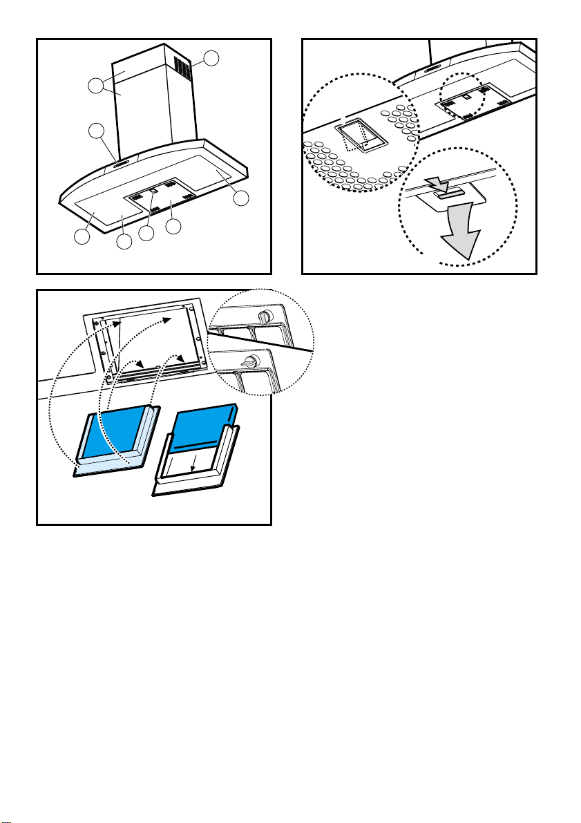
Beschreibung der
Dunstabzugshaube - Abb. 1
1 Bedienfeld
2 Fettfilter
3 Griff zum Aushaken des Fettfilters
4 Lampe
5 Dunstschirm (Ober- und Unterteil)
6 Teleskopkamin
7 Luftaustritt (nur bei Umluftbetrieb)
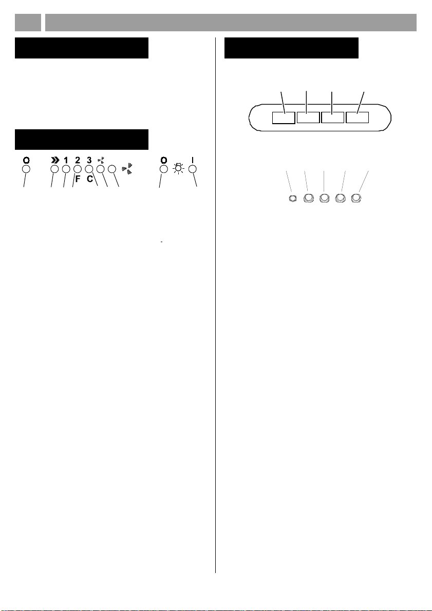
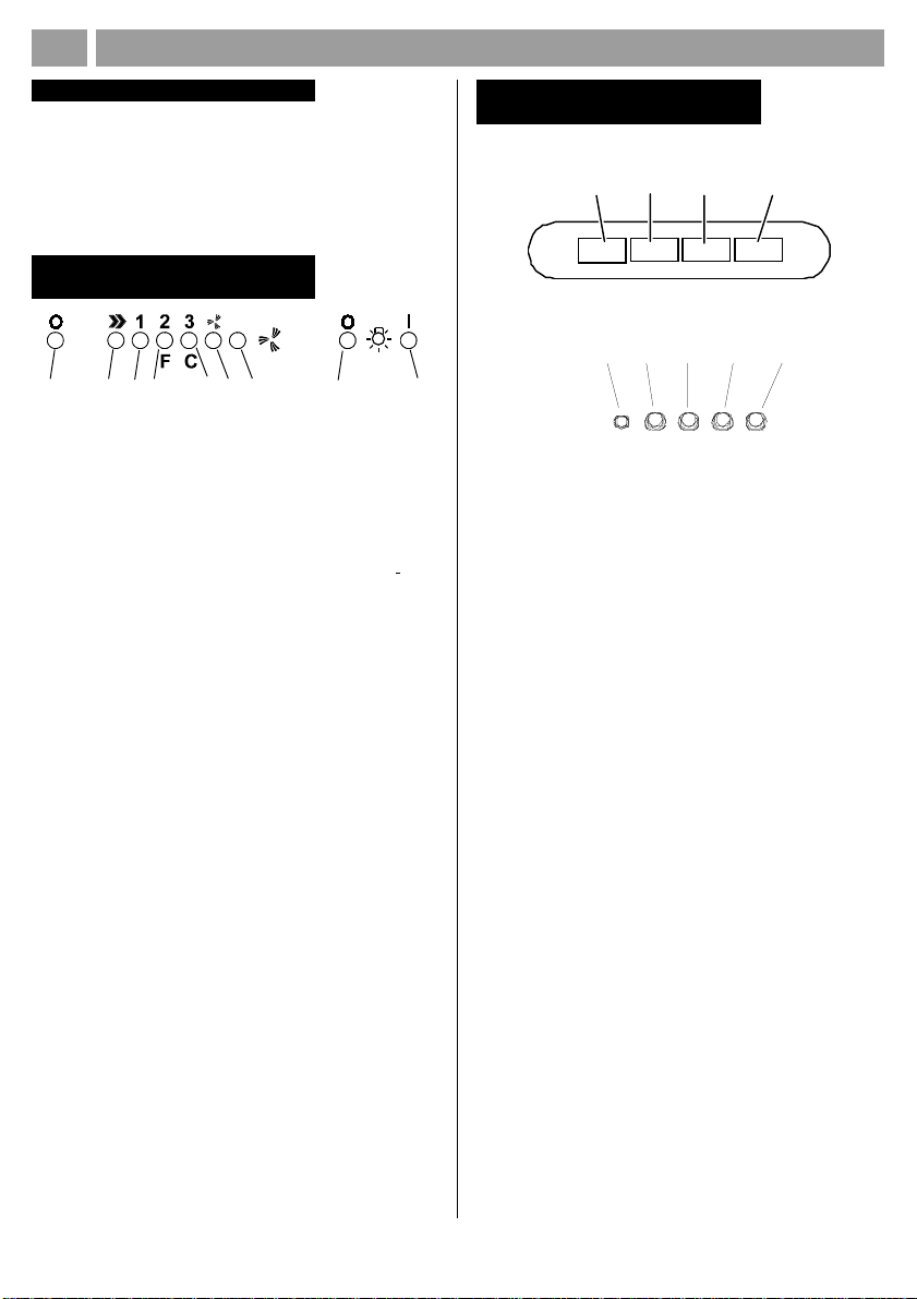
Betrieb – Modell mit
elektronischen Steuerungen
2
1
1. Ausschalter
2. Einschalter und Auswahl der Lüfterstufe 1-2-3-1-2
3. Stufe 1
4. Stufe 2 und Sättigungsanzeige Metallfettfilter (in letzterem Fall
blinkt die Anzeige - siehe Anleitungen zur Reinigung der
Fettfilter).
5. Stufe 3 und Sättigungsanzeige Aktiv-Kohlefilter (LED)(in
letzterem Fall blinkt die Anzeige - siehe Anleitungen zum
Wechsel der Aktivkohlefilter).
Achtung!
Die Sättigungsanzeige des Aktivkohlefilters ist deaktiviert.
Soll die Sättigungsanzeige des Aktivkohlefilters aktiviert werden,
3 Sekunden lang gleichzeitig die Tasten 2 und 7 drücken:
zunächst blinkt nur die LED 4 und nach Ablauf der 3 Sekunden
beginnt auch die LED 5 zu blinken und zeigt so an, daß der
Aktivkohlefilter nun aktiv ist.
Für seine Deaktivierung die beiden Tasten erneut drücken:
nach 3 Sekungen stellt die LED 5 das Blinken ein und die
Vorrichtung ist deaktiviert.
6. Intensivstufe - LED-Anzeige
7. Einschalter Intensivstufe
Die Intensivstufe wird für 5 Minuten in Betrieb genommen.
Danach geht die Dunsthaube zu der vorher eingestellten Stufe
zurück bzw. geht aus, wenn keine Stufe eingestellt ist.
Um die Intensivstufe vor den 5 Minuten zu beenden, drücken
Sie den Knopf 1 oder 2.
8. Ausschalter Beleuchtung
9. Ausschalter Beleuchtung
Die Dunstabzugshaube oder die Bedienungselemente funktionieren
nicht: Für mindestens 5 Sekunden die Stromversorgung der
Dunstabzugshaube unterbrechen und dann die Haube erneut
einschalten. Kann die Störung nicht behoben werden, kontaktieren
Sie bitte den Kundendienst.
MONTAGE- UND GEBRAUCHSANWEISUNG
56
34
7
89
Betrieb –
Modell mit Tastenfeld
Beschreibung des Bedienfelds und der Funktionen
b
a
a. Schalter ON/OFF Beleuchtung
b. Schalter ON/OFF der Absaugfunktion und zum Einschalten
der geringsten Saugstärke
c. Schalter zum Einschalten der mittleren Saugstärke
d. Schalter zum Einschalten der maximalen Saugstärke
e. Funktionskontrolleuchte (bei Modellen mit runden Tasten)
Im Falle einer sehr intensiven Küchendunstkonzentration die höchste
Saugstärke einschalten. Es wird empfohlen, die Küchenhaube
schon fünf Minuten vor Beginn des Kochvorganges einzuschalten
und sie nach dessen Beendigung noch ungefähr 15 Minuten
weiterlaufen zu lassen.
cd
Bitte auch die Abbildungen auf den ersten Seiten mit den alphabetischen Bezugnahmen, die im Text wiedergegeben sind, zu Hilfe nehmen. Die
Instruktionen, die in diesem Handbuch, gegeben werden, bitte ganz streng einhalten. Es wird keinerlei Haftung übernommen für mögliche
Mängel, Schäden oder Brände der Küchenhaube, die auf die Nichtbeachtung der Vorschriften in diesem Handbuch zurückzuführen sind.
Page 7
D
Wartung
Vor sämtlichen Wartungsarbeiten muss die
Stromzufuhr der Küchenhaube unterbrochen werden.
Reinigung
Die Küchenhaube muss sowohl innen als auch aussen
häufig gereinigt werden.
Zur Reinigung ein mit denaturiertem Alkohol oder flüssigem
Neutralreiniger getränktes Tuch verwenden. Keine Produkte
nehmen, die Scheuermittel enthalten.
Zur beachtung:
Die Nichtbeachtung der Anweisungen, die die Reinigung der
Dunstabzugshaube und das Auswechseln und die Reinigung
der Filter betreffen, können Brandgefahr verursachen.
Wir empfehlen daher die folgenden Anweisungen zu
beachten.
Fettfilter
Dieser muss einmal monatlich gewaschen werden (bei
Modellen mit elektronischem Bedienfeld jedes Mal, wenn
die LED 4 zu blinken beginnt - siehe vorhergehende Seite).
Das kann mit einem milden Waschmittel von Hand, oder in
der Spülmaschine bei niedriger Temperatur und kurzspülgang
erfolgen.
Der Metallfettfilter kann bei der Reinigung in der Spülmaschine
abfärben, was seine Filtermerkmale jedoch in keiner Weise
beeinträchtigt.
Zwecks Demontage der Fettfilter den Aushakgriff ziehen (f)
- (Abb. 2).
Nur bei Modellen mit elektronischem Bedienfeld:
Nach erfolgter Reinigung des Fettfilters drücken Sie die
Taste 1 (siehe vorherige Seite) für mindestens 3 Sekunden
ein, bis der Signalton ertönt: die LED 4 schaltet sich ab.
Aktivkohlefilter (nur bei der Umluftversion)
Dieser Filter bindet die unangenehmen Gerüche, die beim
Kochen entstehen.
Der Aktivkohlefilter wird alle zwei Monate (bei Modellen mit
elektronischem Bedienfeld jedes Mal, wenn die LED 5 zu
blinken beginnt – siehe vorhergehende Seite) in warmem
Wasser und geeigneten Waschmitteln oder in der
Spülmaschine bei 65°C gewaschen (in diesem Fall den
ollständigen Spülzyklus – ohne zusätzliches Geschirr im
Inneren der Geschirrspülmaschine - einschalten).
Das überschüssige Wasser entfernen, ohne dabei den Filter
zu beschädigen; danach das Vlies aus dem Plastikrahmen
entfernen und dieses bei 100° für 10 Minuten in den Ofen
legen, um es vollständig zu trocknen. Das Vlies muss alle
3 Jahre ausgewechselt werden und weiterhin jedes Mal
dann, wenn es beschädigt ist.
Das Gestell, das den Filter trägt, abnehmen, dafür die Knäufe
(g), die es an der Haube befestigen, um 90° drehen (Abb.
3).
Das Kohlekissen (i) in den Rahmen (h) schieben und alles
wieder an entsprechender Stelle (j) montieren.
Nur bei Modellen mit elektronischem Bedienfeld:
Nach erfolgtem Aktivkohlefilterwechsel drücken Sie die
Taste 1 (siehe vorherige Seite) für mindestens 3 Sekunden
ein, bis der Signalton ertönt: die LED 5 schaltet sich ab.
MONTAGE- UND GEBRAUCHSANWEISUNG
Warnung
Wenn die Dunstabzugshaube gleichzeitig mit Geräten, die
nicht mit elektrischer Energie betrieben werden, in Betrieb
ist, darf der Unterdruck des Raumes 4 pa (4 x 10⁻⁵ bar) nicht
überschreiten. Die Küchenhaube niemals einschalten, ohne
das Gitter korrekt einzusetzen! Die angesaugte Luft darf nicht
in ein Abluftrohr geleitet werden, in das die Abluft von Geräten
geleitet wird, die an eine andere Energiequelle als an die
elektrische angeschlossen sind. Ein Raum, in dem gleichzeitig
eine Küchenhaube und Geräte in Betrieb sind, die an eine
andere Energiequelle als an die elektrische angeschlossen
sind, muss immer gut belüftet werden. Es ist strengstens
verboten, unter der Küchenhaube Speisen auf offener
Flamme zuzubereiten. Offenes Feuer schädigt die Filter und
kann einen Brand verursachen, daher muss dieses in jedem
Falle vermieden werden. Beim Frittieren muss das erhitzte
Öl ständig kontrolliert werden, um zu vermeiden, dass es
in Brand gerät. Was die technischen Abstände und die
Sicherheitsabstände betrifft, die bei der Ableitung der Dämpfe
beachtet werden müssen, so sind die Angaben der
zuständigen örtlichen Behörden strengstens einzuhalten.
Bitte auch die Abbildungen auf den ersten Seiten mit den alphabetischen Bezugnahmen, die im Text wiedergegeben sind, zu Hilfe nehmen. Die
Instruktionen, die in diesem Handbuch, gegeben werden, bitte ganz streng einhalten. Es wird keinerlei Haftung übernommen für mögliche
Mängel, Schäden oder Brände der Küchenhaube, die auf die Nichtbeachtung der Vorschriften in diesem Handbuch zurückzuführen sind.
Page 8
GB
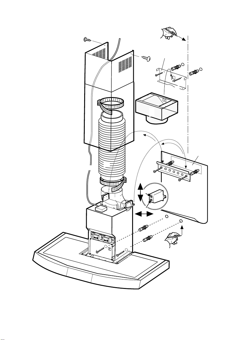
Installation - Fig. 4
The cooker hood must be placed at a minimum distance of 50 cm
from the cooking plane for electric cookers and 75cm for gas or
mixed cookers.
The hood is equipped with a top air outlet B for discharge of fumes
to the outside (Ducting version – exhaust pipe and pipe fixing
clamps not provided).
Should it not be possible to discharge cooking fumes and vapour to
the outside, the hood can be used in the filter version, fitting an
activated carbon filter and the deflector F
on the support (bracket) G, fumes and vapours are recycled through
the top grille H by means of an exhaust pipe connected to the top air
outlet B and the connection ring mounted on the deflector F (exhaust
pipe and pipe fixing clamps not provided).
The models with no suction motor only operate in ducting mode, and
must be connected to an external suction device (not supplied).
Preliminary information for installation of the hood:
Disconnect the hood during electrical connection, by turning the
home mains switch off.
Expansion wall plugs are provided to secure the hood to
most types of walls/ceilings. However, a qualified technician
must verify suitability of the materials in accordance with the
type of wall/ceiling. The wall/ceiling must be strong enough
to take the weight of the hood.
1. Using a pencil, draw a line on the wall, extending up to
2. Rest the drilling template against the wall: the vertical
3. Rest the support bracket on the drilling template so that
4. Hang the hood on the bracket.
5. Adjust the distance of the hood from the wall.
6. Adjust the horizontal position of the hood.
7. Mark the drill hole, using a pencil, for fastening the hood
8. Remove the hood from the bracket.
9. Drill at the point marked (Ø8mm - see operation 7).
10. Insert 2 wall plugs.
11. Rest the chimney support bracket G against the wall,
Consult the designs in the front pages referenced in the text by alphabet letters. Closely follow the instructions set out in this
manual. All responsibility, for any eventual inconveniences, damages or fires caused by not complying with the instructions in
this manual, is declined.
INSTRUCTION ON MOUNTING AND USE
12. Fix the chimney support bracket to the wall using two
5x45mm screws.
13. Hook the hood onto the bottom bracket.
14. Fasten the hood to the wall with 2 x 5x45 mm screws
(ABSOLUTELY NECESSARY).
15. Connect a pipe (pipe and pipe clamps not provided, to
be purchased separately) for discharge of fumes to the
connection ring located over the suction motor unit.
If the hood is to be used in ducting version, the other end of the
pipe must be connected to a device expelling the fumes to the
outside. If the hood is to be used in filter version, fix
deflector F to the chimney support bracket G using 2
screws, and connect the other end of the pipe to the
connection ring on deflector F.
16. Make the electrical connections.
17. Apply the chimney stacks and fasten them (17a) at the
top to the chimney support G (17b) using 2 screws.
Replace the grease filter/s and check that the hood is operating
correctly.
Electrical connection
The electrical tension must correspond to the tension noted on the
label placed inside the cooker hood. Connect the electrical plug,
where provided, to the an easily accessible outlet in conformity with
local standards in force.
Where an electrical plug is not provided (for direct connection to
electrical network) place a standards approved bipolar switch with
the ceiling, to mark the centre. This will facilitate
installation.
centre line printed on the drilling template must correspond
to the centre line drawn on the wall, and the bottom edge
of the drilling template must correspond to the bottom
edge of the hood: bear in mind that, when installation is
complete, the underside of the hood must be at least 50
cm above the cooker top in the case of electric cookers,
and at least 75 cm above the cooker top in the case of
gas or mixed cookers.
it coincides with the dotted rectangle, mark the two outer
holes and drill them, remove the drilling template, insert
2 wall plugs and fix the hood support bracket into place
using two 5x45mm screws.
to the wall (two drill holes are necessary for fastening).
touching the ceiling. Use the support bracket as a drilling
template (the small slot formed on the support must
coincide with the line drawn on the wall as above –
operation 1) and mark 2 holes with a pencil, dril the holes
(Ø8mm), insert 2 wall plugs.
an aperture distance of not less than 3mm (accessible) from the
contacts.
Page 9
abc
d
e
GB
Description of the hood - Fig. 1
1 Control panel
2 Grease filter
3 Grease filter release handle
4 Halogen lamp
5 Vapour screen (superior and inferior)
6 Telescopic chimney
7 Air outlet (used for filter version only)
Operation –
Model with electronic controls
1
1- Motor OFF button
2- ON button and motor speed selection button 1 - 2 - 3 - 1 - 2 -
3- Speed 1 LED
4- Speed 2 LED and metal grease filter saturation LED (in this
5- Speed 3 LED and active carbon filter saturation LED (in this
6 - Intensive speed LED
7 - Intensive speed ON switch
8 - OFF lamp button
9 - ON lamp button
INSTRUCTION ON MOUNTING AND USE
56
2
34
. . . .
latter case, the LED will flash - See instructions on grease filter
cleaning).
latter case, the LED will flash - See instructions on active
carbon filter replacement).
Warning!
The active carbon filter saturation LED is not activated.
In order to activate the active carbon filter saturation indicator,
press buttons 2 and 7 simultaneously for 3 seconds. Initially,
only LED 4 will flash, then after the 3 seconds have passed,
LED 5 will also start flashing, indicating that the active carbon
filter saturation control system is active.
To switch off the system, re-press the same two buttons: after
3 seconds LED 5 will stop flashing and the device will be
switched off.
This speed should be used when the concentration of cooking
fumes or odours is particularly strong (for example when frying,
cooking fish etc.). The fast speed will run for about 5
minutes and then return to the speed previously set automatically
(1, 2 or 3), or switch off if no speed was selected.
To turn off the fast speed, before the end of the 5 minutes, press
button 1 or button 2.
7
89
Operation –
Model with button panel
Description of control panel and hood operation
b
a
a. on/off light switch
b. on/off aspiration switch and minimum power selection
c. medium power selection aspiration switch
d. maximum power selection aspiration switch
e. operating gauge (foreseen in the model with round buttons)
Use the high suction speed in cases of concentrated kitchen
vapours. It is recommended that the cooker hood suction is switched
on for 5 minutes prior to cooking and to leave in operation during
cooking and for another 15 minutes approximately after terminating
cooking.
cd
If the hood fails to operate correctly, briefly disconnect it from the
mains power supply for almost 5 sec. by pulling out the plug. Then
plug it in again and try once more before contacting the Technical
Assistance Service.
Consult the designs in the front pages referenced in the text by alphabet letters. Closely follow the instructions set out in this
manual. All responsibility, for any eventual inconveniences, damages or fires caused by not complying with the instructions in
this manual, is declined.
Page 10

GB
Maintenance
Prior to any maintenance operation ensure that the cooker
hood is disconnected from the power supply.
Cleaning
The cooker hood should be cleaned regularly internally and
externally.
For cleaning use a cloth moistened with denatured alcohol
or neutral liquid detergents. Avoid abrasive detergents.
Warning:
Failure to carry out the basic standards of the cleaning
of the cooker hood and replacement of the filters may
cause fire risks. Therefore we recommend oserving these
instructions.
Grease filter
This must be cleaned once a month (and, for the model with
electronic control panel, every time LED 4 starts to flash –
see preceding page) using non aggressive detergents,
either by hand or in the dish-washer, which must be set to
a low temperature and a short cycle.
When washed in a dish-washer, the grease filter may
discolour slightly, but this does not affect its filtering capacity.
To remove the grease filter, pull the spring release handle
(f) - (Fig. 2).
Only for model with electronic control panel:
Once the grease filters have been cleaned, press button 1
(see preceding page) for about 3 seconds until you hear the
acoustic signal (beep): the LED 4 will now stop flashing.
Charcoal filter (filter version only)
It absorbs unpleasant odours caused by cooking.
The charcoal filter can be washed once every two months
(and, for the model with electronic control panel, every time
LED 5 starts to flash – see preceding page) using hot water
and a suitable detergent, or in a dish-washer at 65°C (if the
dish-washer is used, select the full cycle function and leave
dishes out).
Eliminate excess water without damaging the filter, then
remove the mattress located inside the plastic frame and put
it in the oven for 10 minutes at 100° C to dry completely.
Replace the mattress every 3 years and when the cloth is
damaged.
Remove the filter holder frame by turning the knobs (g) 90°
that affix the chimney to the cooker hood (Fig. 3).
Insert the pad (i) of activated carbon into the frame (h) and
fit the whole back into its housing (j).
INSTRUCTION ON MOUNTING AND USE
Attention
This appliance is designed to be operated by adults. Children
should not be allowed to tamper with the controls or play with
the appliance.
Do not use the cooker hood where the grill is not correctly
fixed! The suctioned air must not be conveyed in the same
channel used for fumes discharged by appliances powered
by other than electricity. The environment must always be
adequately aerated when the cooker hood and other
appliances powered by other than electricity are used at the
same time. Flambé cooking with a cooker hood is
prohibited. The use of a free flame is damaging to the filters
and may cause fire accidents, therefore free flame cooking
must be avoided. Frying of foods must be kept under close
control in order to avoid overheated oil catching fire. Carry
out fumes discharging in accordance with the regulations in
force by local laws for safety and technical restrictions.
Only for model with electronic control panel:
Once you have replaced the charcoal filter, press button 1
(see preceding page) for about 3 seconds until you hear the
acoustic signal (beep).
LED 5 will now stop flashing.
Consult the designs in the front pages referenced in the text by alphabet letters. Closely follow the instructions set out in this
manual. All responsibility, for any eventual inconveniences, damages or fires caused by not complying with the instructions in
this manual, is declined.
Page 11

PRESCRIPTIONS DE MONTAGE ET MODE D’EMPLOI
F
Installation - Fig. 4
Si vous possédez un plan de cuisson entièrement électrique,
la hotte doit etre installée à une distance de 50 cm , de 75
cm dans le cas d’un plan de cuisson mixte ou à gaz.
La hotte est équipée d’une sortie de l’air supérieure B pour l’évacuation
des fumées vers l’extérieur (Version aspirante – tuyau d’évacuation
et colliers de fixation non fournis).
Dans l’éventualité où il ne serait pas possible d’évacuer les fumées
et les vapeurs de cuisson vers l’extérieur, il est possible d’utiliser la
hotte dans la version filtrante, en effectuant le montage d’un filtre
à charbon actif et d’un déflecteur F sur le support (bride) G; les
fumées et les vapeurs sont recyclées à travers le grillage supérieur
H, au moyen d’un tuyau d’évacuation connecté à la sortie d’air
supérieure B et à la bague de connexion montée sur le déflecteur F
(tuyau d’évacuation et colliers de fixation non fournis).
Les modèles sans moteur d’aspiration fonctionnent uniquement
dans la version aspirante et ils doivent être connectés à une unité
périphérique d’aspiration (non fournie).
Informations préliminaires pour l’installation de la hotte:
Débrancher la hotte, en intervenant sur le tableau électrique général
domestique, pendant les phases de branchement électrique.
La hotte est équipée de chevilles de fixation convenant à la
plupart des parois/plafonds. Il est cependant nécessaire de
s’adresser à un technicien qualifié afin de s’assurer que le
matériel est approprié au type de paroi/plafond. Le paroi/
plafond doit être suffisamment solide pour supporter le poids
de la hotte.
1. Au moyen d’un crayon, tracer une ligne sur la paroi,
jusqu’au plafond, en correspondance de la ligne médiane
afin de faciliter les opérations d’installation.
2. Appliquer le schéma de perçage contre la paroi: la ligne
médiane verticale imprimée sur le schéma de perçage
devra correspondre à la ligne médiane dessinée sur le
mur. Le bord inférieur du schéma de perçage devra
également correspondre au bord inférieur de la hotte: il
faut tenir compte du fait que, après avoir terminé
l’installation, le côté inférieur de la hotte doit se trouver
à 50 cm. au moins de distance par rapport au plan de
cuisson, en cas de fourneaux électriques, et à 75 cm.
en cas de fourneaux à gaz ou mixtes.
3. Poser la bride de support sur le schéma de perçage, en
le faisant coïncider avec le rectangle hachuré, marquer
les deux trous externes puis percer les trous, retirer le
schéma de perçage, insérer 2 chevilles pour le mur et
fixer la bride de support de la hotte à l’aide de 2 vis de
5x45 mm.
4. Suspendre la hotte sur la bride.
5. Régler la distance de la hotte par rapport à la paroi.
6. Régler la position horizontale de la hotte.
7. Avec un crayon, tracer un trou pour la fixation définitive
de la hotte (deux points de fixation sont nécessaires pour
la fixation définitive).
8. Retirer la hotte de la bride.
9. Percer un trou en correspondance du point marqué (ø
8 mm. – voir opération 7).
10. Insérer 2 chevilles à mur.
11. Appliquer la bride de support des cheminées G contre
la paroi qui touche le plafond; utiliser la bride de support
en tant que schéma de perçage (le petit oeillet obtenu sur
le support doit coïncider avec la ligne précédemment
tracée sur le mur – opération 1) puis marquer 2 trous à
l’aide d’un crayon, percer les trous (ø 8 mm.), insérer
les deux chevilles.
12. Fixer la bride de support des cheminées contre la paroi,
à l’aide de deux vis de 5x45 mm.
13. Accrocher la hotte sur la bride inférieure.
14. Fixer définitivement la hotte à la paroi avec 2 vis
5x45mm (ABSOLUMENT NECESSAIRE).
15. Effectuer la connexion entre le tuyau (tuyau et colliers
de fixation non fournis, à acheter séparément) pour
l’évacuation des fumées et la bague de connexion qui
se trouve au-dessus de l’unité moteur d’aspiration.
L’autre extrémité du tuyau devra être connectée à un dispositif
d’évacuation des fumées vers l’extérieur, en cas d’emploi de la
hotte dans la version aspirante. Si l’on souhaite utiliser la hotte
dans la version filtrante, il faudra fixer à la bride de support des
cheminées G le déflecteur F, à l’aide de 2 vis et connecter
l’autre extrémité du tuyau à la bague de connexion qui
se trouve sur le déflecteur F.
16. Effectuer le branchement électrique.
17. Appliquer les cheminées et fixer ces dernières en haut
à l’aide de 2 vis (17a) sur le support des cheminées G
(17b).
Remonter le/s filtre/s anti-graisse, puis contrôler le fonctionnement
parfait de la hotte.
Branchement électrique
La tension du réseau doit correspondre à la tension indiquée sur
l’étiquette des caractéristiques située dans la hotte. Si la hotte est
fournie avec une fiche, la raccorder à une prise accessible conforme
aux normes en vigueur. Si la hotte est fournie sans fiche ( branchement
direct sur le réseau), la raccorder à un interrupteur bipolaire normalisé
ayant une distance des contacts supérieure à 3 mm (accessible).
Consulter les dessins de la première page avec les références alphabétiques que l’on retrouvera dans le texte explicatif.
Suivre strictement les instructions de cette notice. Le constructeur décline toute responsabilité pour tous les inconvenients, dommages ou incendies
provoquès à l’appareil et dus à la non observation des instructions de la présente notice.
Page 12

abc
d
e
PRESCRIPTIONS DE MONTAGE ET MODE D’EMPLOI
F
Description de la hotte – Fig. 1
1 Panneau de contrôle
2 Filtre anti-graisse
3 Poignée de décrochage du filtre anti-graisse
4 Lampe halogène
5 Écran vapeurs (supérieur et inférieur)
6 Cheminée télescopique
7 Sortie de l’air (uniquement pour emploi dans la version
filtrante)
Fonctionnement – Modèle
avec contrôles électroniques
56
2
1
1- Bouton pour éteindre le moteur.
2- Bouton d’enclenchement du moteur et de sélection de vitesse
3- DEL de vitesse 1
4- DEL de vitesse 2 et témoin DEL de saturation du filtre anti-
5- DEL de vitesse 3 et témoin DEL de saturation du filtre à
6 - Indicateur DEL de vitesse intensive
7 - Bouton d’enclenchement de vitesse intensive. Cette vitesse
8 - Bouton pour éteindre l’éclairage
9 - Bouton pour allumer l’éclairage
Consulter les dessins de la première page avec les références alphabétiques que l’on retrouvera dans le texte explicatif.
Suivre strictement les instructions de cette notice. Le constructeur décline toute responsabilité pour tous les inconvenients, dommages ou incendies
provoquès à l’appareil et dus à la non observation des instructions de la présente notice.
34
1 - 2 - 3 - 1 - 2 -...
graisse métallique (dans ce dernier cas le témoin clignotera Voir indications relatives au remplacement des filtres à charbon
actif).
charbon actif (dans ce dernier cas le témoin clignotera - Voir
indications relatives au remplacement des filtres à charbon
actif).
Attention!
Le dispositif de signalisation du niveau de saturation du filtre à
charbon actif est désactivé.
Si vous souhaitez activer le dispositif de signalisation du niveau
de saturation du filtre à charbon actif, appuyez simultanément
sur les touches 2 et 7 pendant 3 secondes: lors de la première
phase de cette procédure, la DEL 4 clignotera puis, après 3
secondes, la DEL 5 commencera à clignoter, pour indiquer que
le dispositif de contrôle du niveau de saturation du filtre à
charbon actif est désormais activé.
Si vous souhaitez désactiver le dispositif, appuyez à nouveau
sur les touches 2 et 7.
Après 3 secondes la DEL 5 ne clignotera plus et le dispositif
sera désactivé.
est utilisée lorsque la concentration de vapeurs et d’odeurs
culinaires est particulièrement élevée (en cas de fritures, de
mets à base de poisson, etc.). La hotte fonctionnera à cette
vitesse élevée pendant environ 5 minutes puis reviendra à la
vitesse sélectionnée précédemment (1, 2 ou 3) ou s’éteindra
si aucune vitesse n’a été sélectionnée. Pour désactiver la
vitesse intensive avant les 5 minutes préprogrammées, appuyez
sur le bouton 1 ou le bouton 2.
7
89
Si la hotte ne fonctionne pas correctement, débranchez la
prise pendant environ 5 secondes, puis rebranchez-la. Si
le problème persiste, contactez le service de réparation
compétent.
Fonctionnement – Modèle avec
Tableau à poussoirs
Description du panneau de contrôle et fonctionnement de la hotte
b
a
a.touche ON/OFF éclairage
b.touche OFF/ON aspiration et sélection puissance minimum
c.touche selection puissance d’aspriration moyenne
d.touche selection puissance d’aspiration maximum
e.lampe témoin de fonctionnement (prévue dans le modèle avec
touches rondes)
Utiliser la puissance d’aspiration maximum en cas de concentration
très importante des vapeurs de cuisson. Nous conseillons d’allumer
le dispositif d’aspiration 5 minutes avant de commencer la cuisson
et de le faire fonctionner encore pendant 15 minutes environ après
avoir terminé la cuisson.
cd
Page 13

PRESCRIPTIONS DE MONTAGE ET MODE D’EMPLOI
F
Entretien
Veillez a débrancher la hotte du réseau electrique avant toute
intervention sur celle- ci.
Nettoyage
La hotte doit etre regulièrement nettoyée à l’intérieur et à
l’extérieur.
Pour le nettoyage, utiliser un chiffon humide imbibé d’alcool
dénaturé ou de détergents liquides neutres. Eviter d’utiliser
des produits abrasifs.
Attention:
Le non respect des règles de nettoyage de la hotte, de la
substitution et du nettoyage des filtres comporte des risques
d’incendie.
Nous recommandons donc vivement de respecter ces
instructions.
Filtre anti-gras
Le filtre doit être nettoyé une fois par mois (et, dans le cas
du modèle avec panneau de contrôle électronique, chaque
fois que la DEL 4 clignote – voir page précédente), avec des
détergents non agressifs, à la main ou dans le lave-vaisselle
à faibles températures et cycle rapide.
Le lavage du filtre anti-graisse métallique au lave-vaisselle
peut en provoquer la décoloration.
Toutefois, les caractéristiques de filtrage ne seront en aucun
cas modifiées.
Pour démonter le filtre anti-graisse, tirer la poignée de
décrochement à ressort (f) – (Fig. 2).
Pour le modèle avec panneau de contrôle électronique
uniquement:
Une fois que le filtre anti-gras a été nettoyé, appuyez sur le
bouton 1 (voir page précédente) pendant environ 3 secondes
jusqu’à ce que vous entendiez le signal sonore; le DEL 4
s’arrêtera alors de clignoter.
Pour le modèle avec panneau de contrôle électronique
uniquement:
Une fois que le filtre à charbon actif a été nettoyé, appuyez
sur le bouton 1 (voir page précédente) pendant environ 3
secondes jusqu’à ce que vous entendiez le signal sonore;
le DEL 5 s’arrêtera alors de clignoter.
Attention
Ne jamais utiliser la hotte sans avoir installé correctement
la grille! L’air aspiré ne doit pas etre expulsé dans un conduit
utilisé pour l’échappement des fumées d’appareils alimentés
avec une énergie autre que l’énergie électrique. Il faut prévoir
une bonne aération du local lorsque l’on utilise simultanément
une hotte et des appareils alimentés avec une autre énergie
que l’electricité. Il est strictement défendu de faire flamber des
aliments sous la hotte. Toute flamme sous la hotte peut
endommager les filtres et causer un incendie. La friture doit
etre surveillée pour éviter que l’huile surchauffée ne
s’enflamme. Pour des raisons techniques et de sécurité
veuillez suivre scrupuleusement les réglementations locales
relatives à l’évacuation des fumées.
Filtre à charbon actif (uniquement pour version
recyclage)
Retient les odeurs désagréables de cuisson.
Le filtre à charbon peut être nettoyé tous les deux mois (et,
dans le cas du modèle avec panneau de contrôle électronique,
chaque fois que la DEL 5 clignote – voir page précédente)
avec de l’eau chaude et au moyen de détergents appropriés
ou dans le lave-vaisselle à 65°C (dans le cas de lavage
dans le lave-vaisselle suivre un cycle de lavage complet
sans vaisselle à l’intérieur).
Enlever l’eau qui excède en faisant attention de ne pas
abîmer le filtre, ensuite enlever le coussinet posé à l’intérieur
du châssis en plastique et le mettre dans le four pendant 10
minutes à 100°C pour le sécher définitivement. Remplacer
le coussinet tous les 3 ans et chaque fois que le filtre sera
abîmé.
Enlever le châssis de support filtre en tournant de 90° les
boutons (g) qui le fixent à la hotte (Fig. 3).
Introduire le coussinet (i) au charbon à l’intérieur du châssis
(h), puis remonter le tout dans le logement spécialement
prévu à cet effet (j).
Consulter les dessins de la première page avec les références alphabétiques que l’on retrouvera dans le texte explicatif.
Suivre strictement les instructions de cette notice. Le constructeur décline toute responsabilité pour tous les inconvenients, dommages ou incendies
provoquès à l’appareil et dus à la non observation des instructions de la présente notice.
Page 14

NL
Installatie - afb. 4
In het geval van een elektrisch fornuis moet de afzuigkap
minstens 50 cm van de kookplaat afgelegen zijn en 75 cm
in geval van gas of gemengd fornuis.
De wasemkap heeft een luchtuitgang aan de bovenkant B voor de
afvoer van de dampen naar buiten (Uitvoering als afzuigend apparaat
– afvoerpijp en bevestigingsbandjes niet meegeleverd).
Als het niet mogelijk is de rook en kookdampen naar buiten af te
voeren, kan de wasemkap worden gebruikt als filterend apparaat,
door een koolstoffilter te monteren en het afbuigrooster F op de
steun (beugel) G aan te brengen; de rook en dampen worden weer
teruggebracht in het vertrek via de roosters aan de bovenzijde H, via
een afvoerbuis die is aangesloten op de luchtuitgang aan de
bovenzijde B en de aansluitring die gemonteerd is op het
luchtafbuigrooster F (afvoerpijp en bevestigingsbandjes niet
meegeleverd).
De modellen zonder afzuigmotor werken alleen als apparaten met
afvoer van de lucht naar buiten, en moeten worden verbonden met
een perifere afzuigunit (niet meegeleverd).
Voorafgaande informatie voor installatie van de wasemkap:
Koppel de wasemkap tijdens het maken van de elektrische
aansluiting af van het elektriciteitsnet via de hoofdschakelaar
in uw woning.
De wasemkap is voorzien van bevestigingspluggen die
geschikt zijn voor de meeste muurs/plafonds. Er moet
echter contact opgenomen worden met een gekwalificeerd
technicus om u ervan te vergewissen dat de materialen
geschikt zijn voor het type muur/plafond. Het muur/plafond
moet stevig genoeg zijn om het gewicht van de kap te
houden.
1. Teken met een potlood een lijn op de muur tot aan het
2 Houd de boormal tegen de muur: de verticale middellijn
3. Houd de draagbeugel tegen de boormal en laat hem
4. Hang de wasemkap aan de beugel.
5. Regel de afstand van de wasemkap tot de muur.
6. Regel de horizontale positie van de wasemkap.
7. Teken met een potlood het gat om de wasemkap definitief
8. Haal de wasemkap van de beugel.
MONTAGEVOORSCHRIFTEN EN GEBRUIKSAANWIIZING
plafond, die correspondeert met de middellijn van het
apparaat; dit vergemakkelijkt de installatie.
op de boormal moet corresponderen met de middellijn
die op de muur getekend is, bovendien correspondeert
de onderkant van de boormal met de onderkant van de
wasemkap: denk eraan dat de onderkant van de
wasemkap na de installatie minstens 50 cm boven de
kookplaat moet zitten bij een elektrische kookplaat, en
75 cm bij een gas- of gemengde kookplaat.
samenvallen met de rechthoek die getekend is met een
stippellijn, teken de twee externe gaten en boor deze,
haal de boormal weg, steek 2 pluggen in de muur en zet
de draagbeugel van de wasemkap vast met 2 schroeven
van 5x45 mm.
vast te zetten (er zijn twee definitieve hechtpunten
nodig).
9. Boor het gat op het aangegeven punt (Ø 8 mm – zie
handeling 7).
10 Steek 2 pluggen in de muur.
11. Bevestig de draagbeugel van de schouwdelen G aan
de muur, aansluitend aan het plafond, gebruik de
draagbeugel als boormal (de kleine uitsparing op de
steun moet samenvallen met de eerder op de muur
getrokken lijn – handeling 4) en teken met het potlood 2
gaten, boor de gaten (Ø8 mm), steek er 2 pluggen in.
12. Bevestig de draagbeugel van de schouwdelen aan de
muur met 2 schroeven van 5x45 mm.
13. Haak de wasemkap aan de onderste beugel.
14. Bevestig de wasemkap definitief aan de muur met 2
schroeven van 5x45mm (ABSOLUUT NODIG).
15. Sluit een rookafvoerpijp aan (pijp en bevestigingsbandjes
worden niet meegeleverd, moeten apart worden
aangeschaft) aan de aansluitring boven de
afzuigmotoreenheid.
Het andere uiteinde van de pijp moet worden aangesloten op
een rookafvoermechanisme naar buiten, als de wasemkap
gebruikt wordt als afzuigapparaat. Als u de wasemkap wilt
gebruiken als filterend apparaat, moet het
luchtafbuigrooster F aan de draagbeugel van de
schouwdelen G worden bevestigd met 2 schroeven, en
moet het andere uiteinde van de pijp worden verbonden
met de aansluitring op het afbuigrooster F.
16. Maak de elektrische aansluiting.
17. Breng de schouwdelen aan en zet hen aan de bovenkant
vast met 2 schroeven (17a) aan de steun van de
schouwdelen G (17b).
Monteer het vetfilter/de vetfilters weer en controleer of de wasemkap
perfect functioneert.
Elektrische aansluiting
De netspanning moet corresponderen met de spanning die vermeld
wordt op het etiket met eigenschappen, aan de binnenkant van de
wasemkap. Als de wasemkap een stekker heeft, moet deze in een
stopcontact worden gestoken dat voldoet aan de geldende
voorschriften en goed te bereiken is. Heeft de kap geen stekker
(rechtstreekse verbinding met het net), dan moet er een tweepolige
schakelaar worden geplaatst met een afstand tussen de contacten
bij opening van minimaal 3 mm (ook deze moet aan de normen
voldoen en gemakkelijk bereikbaar zijn).
Raadpleeg ook de tekeningen uit de eerste bladzijden met de alfabetische verwijzingen uit de toelichtende tekst.
Zich strikt aan de aanwijzingen uit deze tekst houden. Iedere aansprakelijkheid voor eventuele schade of brand aan het apparaat veroorzaakt door
het niet in acht nemen van de aanwijzingen in deze handleiding weergegeven wordt afgewezen.
Page 15

abc
d
e
NL
Beschrijving van
de wasemkap - afb. 1
1 Bedieningspaneel
2 Vetfilter
3 Handgreep voor ontgrendeling van het vetfilter
4 Halogeenlamp
5 Dampscherm (bovenste en onderste)
6 Telescopische schouw
7 Luchtuitgang (alleen voor gebruik als filterend apparaat)
Werking – Model met
elektronische besturingen
1
1 - OFF Knop motor
2 - ON knop en tevens motor snelheidsknop 1 - 2 – 3 - 1-2…
3 - Led snelheid 1
4 - Led snelheid 2 en verzadigde vetfilter (in dit geval gaat het
5 - Led snelheid 3 en verzadigde koolstoffilter (in dit geval gaat
6 - Led aanwijzing intensieve snelheid
7 - Knop voor het inschakelen van de intensieve snelheid.
8 - Knop voor het afzetten van de lichten
9 - Knop voor het aanzetten van de lichten
In geval van storingen, voordat U zich tot de assistentie service
wendt, minstens 5 seconden het apparaat van de elektrische
voeding doen, door de stekker uit te trekken, en daarna weer
invoeren. In het geval dat de storing blijft voortbestaan, wendt U zich
tot de assistentie service.
Raadpleeg ook de tekeningen uit de eerste bladzijden met de alfabetische verwijzingen uit de toelichtende tekst.
Zich strikt aan de aanwijzingen uit deze tekst houden. Iedere aansprakelijkheid voor eventuele schade of brand aan het apparaat veroorzaakt door
het niet in acht nemen van de aanwijzingen in deze handleiding weergegeven wordt afgewezen.
MONTAGEVOORSCHRIFTEN EN GEBRUIKSAANWIIZING
Werking – Model met toetsenbord
Beschrijving van het bedieningspaneel en werking van de
56
2
34
lampje flikkeren– zie de aanwijzingen betreffende het reinigen
van de vetfilters).
het lampje flikkeren – zie de aanwijzingen betreffende het
reinigen van de koolstoffilters).
Opgelet! Het controlesysteem voor het aangeven van de
verzadigde koolstoffilter is uitgeschakeld.
In het geval dat men een koolstoffilter wil installeren, het
controlesysteem voor de aanwijzing van verzadigde koolstoffilter
inschakelen, door tegelijkertijd, gedurende 3 seconden, de
knoppen 2 en 7 ingedrukt te houden: aan het begin van deze
handeling zal alleen LED 4 flikkeren, na 3 seconden zal ook
LED 5 flikkeren om aan te geven dat het controlesysteem
verzadigde koolstoffilter ingeschakeld is. Om dit uit te schakelen
weer op de twee knoppen drukken: na 3 seconden zal LED 5
stoppen met flikkeren, de inrichting is uitgeschakeld.
Er wordt aangeraden deze snelheid te gebruiken wanneer de
rook en geur concentratie nogal sterk is (bijvoorbeeld wanneer
er vis gebakken wordt of in geval van frituren).
Nadat de intensieve snelheid is ingeschakeld zal deze 5
minuten lang blijven werken, daarna zal de kap weer in de van
te voren afgestelde snelheid gaan werken (van 1 tot 3) of zal
zelfs uitgaan indien van te voren geen enkele snelheid ingesteld
is. Om de intensieve snelheid uit te schakelen voordat de 5
minuten voorbij zijn knop 1 of knop 2 indrukken.
7
89
wasemkap
a. ON/OFF lichtknop
b. OFF/ON knop voor de zuigfunctie en voor de selectie van de
laagste zuigkracht
c. Knop middelste zuigkracht
d. Knop maximale zuigkracht
e. werkingscontrolelampje (voorzien op het model met ronde
knoppen)
In geval van een sterkere dampconcentratie een hogere zuigkracht
gebruiken.
We raden aan de afzuigkap 5 minuten voordat men begint te koken
aan te doen en deze nog voor ongeveer 15 minuten nadat men
beëindigt heeft aan te laten.
b
a
cd
Page 16

NL
Onderhoud
Koppel voor ieder onderhoud eerst de afzuigkap af van het
elektriciteitsnet.
Schoonmaak
De kap moet regelmatig schoon gemaakt worden, zowel
binnen als buiten.
Voor de schoonmaak een doek met gedenatureerd alcohol
of neutrale reinigingsmiddelen gebruiken. Geen
schuurmiddelen gebruiken.
Attentie:
Het niet in acht nemen van de reinigingsnormen van de
afzuigkap en van de vervanging en reiniging van de filters
kan brandgevaar veroorzaken.
Men wordt dan ook verzocht zich aan de instructies te
houden.
Vetfilter
Moet eenmaal per maand worden gereinigd (en, in het geval
van het model met elektronisch bedieningspaneel, telkens
wanneer LED 4 – knippert, zie vorige pagina ), met neutrale
reinigingsmiddelen, met de hand of in de vaatwasmachine
op lage temperaturen en met een kort programma.
Door hem in de vaatwasmachine te wassen kan het metalen
vetfilter ontkleuren, maar dit is niet van invloed op de
eigenschappen, die
beslist niet veranderen.
Om het vetfilter te demonteren trekt u aan de veerbelaste
ontgrendelingshandgreep (f) - (afb. 2).
Alleen voor het model met elektronisch
bedieningspaneel:
Nadat de vetfilter vervangen is, ongeveer 3 seconden op
toets 1 (zie vorige bladzijde) drukken, totdat het systeem een
pieptoon laat horen.
Led 4 zal stoppen met knipperen.
MONTAGEVOORSCHRIFTEN EN GEBRUIKSAANWIIZING
Alleen voor het model met elektronisch
bedieningspaneel:
Nach erfolgtem Aktivkohlefilterwechsel drücken Sie die
Taste 1 (siehe vorherige Seite) für mindestens 3 Sekunden
ein, bis der Signalton ertönt: die LED 5 schaltet sich ab.
Waarschuwing
De afzuigkap nooit gebruiken als het rooster niet goed
gemonteerd is! De gezogen lucht mag niet afgevoerd
worden in een leiding die gebruikt wordt voor de afvoer van
rook van apparaten met een andere voeding als de
elektrische energiebron. Altijd voor een goede ventilatie van
de ruimte zorgen als de afzuigkap en de apparaten met
andere energiebron gebruikt worden. Het is streng verboden
met open vlammen onder de afzuigkap te koken. Het gebruik
van open vlammen is schadelijk voor de filters en kan brand
veroorzaken, daarom moet het in ieder geval vermeden
worden. Het frituren moet geschieden met voortdurende
controle om te voorkomen dat verhit vet in brand raakt. Wat
betreft technische en veiligheidsmaatregelen voor de
rookafvoer zich strikt houden aan de regelingen voorzien
door de plaatselijke bevoegde autoriteiten.
Koolstoffilter (alleen voor filterend apparaat)
Houdt de lastige kookgeuren vast.
De koolstoffilter kan om de twee maanden gewassen
worden (en, in het geval van het model met elektronisch
bedieningspaneel, telkens wanneer LED 5 – knippert, zie
vorige pagina) in warm water en met geschikte wasmiddelen
of in de vaatmachine op 65°C (in het geval van een reiniging
in de vaatmachine voer een volledige wascyclus uit en
zonder vaten).
Verwijder het overtollige water zonder de filter te beschadigen,
daarna het matje uit de plastic structuur verwijderen en om
deze goed te drogen doe het matje in de over voor 10 minuten
op 100°C. Vervang het matje om de 3 jaar en elke keer dat
het doek beschadigt is.
Verwijder het filterhouder frame door de onderdelen (g), die
het aan de wasemkap bevestigen, 90° te draaien (afb. 3).
Breng het koolstofmatrasje (i) aan in het frame (h) en monteer
het geheel op zijn plaats (j).
Raadpleeg ook de tekeningen uit de eerste bladzijden met de alfabetische verwijzingen uit de toelichtende tekst.
Zich strikt aan de aanwijzingen uit deze tekst houden. Iedere aansprakelijkheid voor eventuele schade of brand aan het apparaat veroorzaakt door
het niet in acht nemen van de aanwijzingen in deze handleiding weergegeven wordt afgewezen.
Page 17

I
Installazione - Fig. 4
La cappa deve avere una distanza minima dal piano cottura di 50 cm
in caso di cucine elettriche e di 75 cm in caso di cucine a gas o miste.
La cappa è fornita di una uscita d‘aria superiore B per lo scarico dei
fumi verso l'esterno (Versione aspirante- tubo di scarico e fascette
di fissaggio non fornite).
Nel caso non sia possibile scaricare i fumi e vapori della cottura verso
l‘esterno, si può utilizzare la cappa in versione filtrante montando un
filtro ai carboni attivi e il deflettore F sul supporto (staffa) G, i fumi e
vapori vengono riciclati attraverso la sgrigliatura superiore H tramite
un tubo di scarico collegato all‘uscita d‘aria superiore B e l‘anello di
connessione montato sul deflettore F (tubo di scarico e fascette di
fissaggio non fornite).
I modelli senza motore di aspirazione funzionano solo in versione
aspirante e debbono essere collegati ad una unità periferica di
aspirazione (non fornita).
Informazioni preliminari per l‘installazione della cappa:
Scollegare la cappa agendo sul quadro generale domestico nelle
fasi del collegamento elettrico.
La cappa è dotata di tasselli di fissaggio adatti alla maggior
parte di pareti/soffitti. E’ tuttavia necessario interpellare un
tecnico qualificato per accertarVi sull’idoneità dei materiali a
seconda del tipo di parete/soffitto. Il parete/soffitto deve
essere sufficientemente robusto da sostenere il peso della
cappa.
1. Con una matita, eseguire una linea sulla parete, sino al
soffitto, corrispondente alla linea di mezzeria, faciliterà
le operazioni di installazione.
2. Applicare lo schema di foratura al muro: la linea verticale
di mezzeria stampata sullo schema di foratura dovrà
corrispondere alla linea di mezzeria disegnata sul muro,
inoltre il bordo inferiore dello schema di foratura corrisponde
al bordo inferiore della cappa: tenere presente che il lato
inferiore della cappa , ad installazione ultimata, deve
distare dal piano di cottura almeno 50cm in caso di fuochi
elettrici e 75 cm in caso di fuochi a gas o misti.
3. Appoggiare la staffa di supporto sullo schema di foratura
facendolo coincidere con il rettangolo tratteggiato, segnare i
due fori esterni e forare, togliere lo schema di foratura, inserire
2 tasselli a muro e fissare con 2 viti 5x45mm la staffa di supporto
della cappa.
4. Appendere la cappa alla staffa.
5. Regolare la distanza della cappa dalla parete.
6. Regolare l’assetto orizzontale della cappa.
7. Segnare con una matita il foro per il fissaggio definitivo
della cappa (sono necessari due punti di fissaggio
definitivo).
8. Togliere la cappa dalla staffa.
9. Forare nel punto marcato (Ø8mm - vedi operazione 7).
10. Inserire 2 tasselli a muro.
11. Applicare la staffa di supporto camini G alla parete
aderente al soffitto, utilizzare la staffa di supporto come
schema di foratura (la piccola asola ricavata sul supporto
ISTRUZIONI DI MONTAGGIO E D’USO
deve coincidere con la linea precedentemente tracciata
sul muro - operazione 1) e segnare con la matita 2 fori,
eseguire i fori (Ø8mm), inserire 2 tasselli.
12. Fissare la staffa di supporto camini alla parete con 2 viti
5x45mm.
13. Agganciare la cappa alla staffa inferiore.
14. Fissare definitivamente la cappa alla parete con 2 viti
5x45mm (ASSOLUTAMENTE NECESSARIE).
15. Eseguire la connessione di un tubo (tubo e fascette per
il fissaggio non fornite, da acquistare) per lo scarico dei
fumi all’anello di connessione posto sopra l’unità motore
aspirante.
L’altra estremità del tubo dovrà essere collegata ad un dispositivo
di espulsione fumi verso l’esterno in caso di utilizzo della cappa
in versione aspirante. Nel caso si voglia utilizzare la cappa in
versione filtrante, allora fissare alla staffa di supporto
camini G il deflettore F con 2 viti e collegare l’altra
estremità del tubo all’anello di connessione posto sul
deflettore F.
16. Eseguire la connessione elettrica.
17. Applicare i camini e fissarli sopra con 2 viti (17a) al
supporto camini G (17b).
Rimontare il filtro/i grassi e controllare il perfetto funzionamento della
cappa
Collegamento elettrico
La tensione di rete deve corrispondere alla tensione riportata
sull’etichetta caratteristiche situate all’interno della cappa. Se provvisto
di spina allacciare la cappa ad una presa conforme alle norme vigenti
posta in zona accessibile. Se sprovvisto di spina (collegamento
diretto alla rete) applicare un interruttore bipolare a norme con una
distanza dei contatti in apertura non inferiore a 3mm (accessibile).
Consultare anche i disegni nelle prime pagine con i riferimenti alfabetici riportati nel testo esplicativo.
Attenersi strettamente alle istruzioni riportate in questo manuale. Si declina ogni responsabilità per eventuali inconvenienti, danni o incendi provocati
all’apparecchio derivati dall’inosservanza delle istruzioni riportate in questo manuale.
Page 18

I
abc
d
e
Descrizione della cappa - Fig. 1
1 Pannello di controllo
2 Filtro antigrasso
3 Maniglia di sgancio del filtro antigrasso
4 Lampada alogena
5 Schermo vapori (superiore e inferiore)
6 Camino telescopico
7 Uscita aria (solo per utilizzo in versione filtrante)
Funzionamento Modello con controlli elettronici
1
1 - Tasto OFF motore
2 - Tasto ON e tasto di selezione della velocità del
3 - Led indicazione Velocità 1
4 - Led indicazione Velocità 2 e saturazione filtro
5 - Led indicazione Velocità 3 e saturazione filtro ai
6 - Led indicazione velocità intensiva
7 - Tasto inserimento velocità intensiva.
8 - Tasto spegnimento luci
ISTRUZIONI DI MONTAGGIO E D’USO
56
2
34
motore 1 - 2 - 3 - 1 - 2...
antigrasso (in quest'ultimo caso il Led emette una
segnalazione intermittente - Vedere le istruzioni
relative alla pulizia dei filtri antigrasso).
carboni attivi (in quest'ultimo caso il Led emette una
segnalazione intermittente - Vedere le istruzioni
relative alla sostituzione dei filtri ai carboni attivi).
Attenzione! Il dispositivo di segnalazione
saturazione del filtro ai carboni attivi è disattivato.
Nel caso si voglia installare un filtro al carbone attivo,
allora attivare il dispositivo di segnalazione saturazione
filtro al carbone attivo, a tal fine premere
contemporaneamente i tasti 2 e 7 per 3 secondi:
all’inizio di questa procedura lampeggerà solo il LED
4, passati i 3 secondi inizierà a lampeggiare anche
il LED 5 per indicare che il dispositivo di controllo
saturazione filtro al carbone attivo è ora attivo.
Per disattivarlo ripremere i due tasti: dopo 3 secondi
il LED 5 smetterà di lampeggiare, il dispositivo è
disattivato.
Si consiglia di utilizzare questa velocità quando la
concentrazione di fumi e odori e particolarmente
intensa (per esempio quando si cucina del pesce o
si eseguono delle fritture).
Una volta inserita, la velocità intensiva rimarrà in
funzione per 5 minuti circa,dopodiché la cappa
ritornerà alla velocità precedentemente selezionata
(da 1 a 3) o addirittura si spegne se precedentemente
non era stata selezionata nessuna velocità. Per
disinserire l’intensivo prima che siano passati i 5
minuti premere il tasto 1 o il tasto 2.
7
89
9 - Tasto accensione luci
In caso di eventuali anomalie di funzionamento,
prima di rivolgerVi al servizio assistenza scollegate
per almeno 5 sec. l’apparecchio dall’alimentazione
elettrica estraendo la spina e collegatelo poi
nuovamente. Nel caso in cui l’anomalia di
funzionamento dovesse perdurare, rivolgersi al
servizio d’assistenza.
Funzionamento Modello con Pulsantiera
Descrizione pannello di controllo e funzionamento
della cappa
a.tasto ON/OFF luci
b.tasto OFF/ON aspirazione e selezione potenza minima
c.tasto selezione potenza di aspirazione media
d.tasto selezione potenza di aspirazione massima
e. spia di funzionamento (prevista nel modello con pulsanti
rotondi)
Usare la potenza di aspirazione maggiore in caso di
particolare concentrazione di vapori di cucina. Consigliamo
di accendere l’aspirazione 5 minuti prima di iniziare a
cucinare e di lasciarla in funzione a cottura terminata per altri
15 minuti circa.
b
a
cd
Consultare anche i disegni nelle prime pagine con i riferimenti alfabetici riportati nel testo esplicativo.
Attenersi strettamente alle istruzioni riportate in questo manuale. Si declina ogni responsabilità per eventuali inconvenienti, danni o incendi provocati
all’apparecchio derivati dall’inosservanza delle istruzioni riportate in questo manuale.
Page 19

I
Manutenzione
Prima di qualsiasi lavoro di manutenzione scollegare la
cappa dalla corrente.
Pulizia
La cappa va frequentemente pulita, sia internamente che
esternamente. Per la pulizia usare un panno inumidito con
alcool denaturato o detersivi liquidi neutri. Evitare l’uso di
prodotti contenenti abrasivi.
Attenzione:
L’inosservanza delle norme di pulizia della cappa e della
sostituzione e pulizia dei filtri comporta rischi di incendi. Si
raccomanda quindi di attenersi alle istruzioni suggerite.
Filtro antigrasso
Deve essere pulito una volta al mese(e, nel caso di modello
con pannello di controllo elettronico, ogni volta che lampeggia
il LED 4 - vedi pagina precedente), con detergenti non
aggressivi, manualmente oppure in lavastoviglie a basse
temperature ed a ciclo breve.
Con il lavaggio in lavastoviglie il filtro antigrasso metallico
può scolorirsi ma le sue caratteristiche di filtraggio non
cambiano assolutamente.
Per smontare il filtro grassi tirare la maniglia di sgancio a
molla (f) - (Fig. 2).
Solo per modello con pannello di controllo elettronico:
Dopo aver lavato il filtro antigrasso, premere il tasto 1 (vedi
pagina precedente) per 3 secondi circa, sino a che il sistema
emette un segnale acustico (bip).
Il led 4 smetterà di lampeggiare.
ISTRUZIONI DI MONTAGGIO E D’USO
Avvertenze
Mai utilizzare la cappa senza griglia correttamente montata!
L'aria aspirata non deve essere convogliata in un condotto
usato per lo scarico dei fumi di apparecchi alimentati con
energia diversa da quella elettrica. Deve essere sempre
prevista un'adeguata areazione del locale quando una
cappa e apparecchi alimentati con energia diversa da quella
elettrica vengono usati contemporaneamente. E’
severamente vietato fare cibi alla fiamma sotto la cappa.
L’impiego di fiamma libera è dannoso ai filtri e può dar luogo
ad incendi, pertanto deve essere evitato in ogni caso. La
frittura deve essere fatta sotto controllo onde evitare che l’olio
surriscaldato prenda fuoco. Per le misure tecniche e di
sicurezza da adottare per lo scarico dei fumi attenersi
strettamente a quanto previsto dai regolamenti delle autorità
locali competenti.
Filtro al carbone (solo per versione filtrante)
Trattiene gli odori sgradevoli derivanti dalla cottura.
Il filtro al carbone può essere lavato ogni due mesi (e, nel
caso di modello con pannello di controllo elettronico, ogni
volta che lampeggia il LED 5 - vedi pagina precedente) in
acqua calda e detergenti idonei o in lavastoviglie a 65°C (in
caso di lavaggio in lavastoviglie eseguire il ciclo di lavaggio
completo senza stoviglie all‘interno).
Togliere l‘acqua in eccesso senza rovinare il filtro, dopodiché
togliere il materassino posto all‘interno del telaio in plastica
e riporlo nel forno per 10 minuti a 100°C per asciugarlo
definitivamente.
Sostituire il materassino ogni 3 anni e ogni volta che il panno
risulta danneggiato.
Rimuovere il telaio reggi filtro girando di 90° i pomelli (g) che
lo fissano alla cappa (Fig. 3).
Inserire il materassino (i) di carbone all’interno del telaio (h)
e rimontare il tutto nella apposita sede (j).
Solo per modello con pannello di controllo elettronico:
Dopo aver lavato o sostituito il filtro a carbone attivo, premere
il tasto 1 (vedi pagina precedente) per 3 secondi circa, sino
a che il sistema emette un segnale acustico (bip).
Il led 5 smetterà di lampeggiare.
Consultare anche i disegni nelle prime pagine con i riferimenti alfabetici riportati nel testo esplicativo.
Attenersi strettamente alle istruzioni riportate in questo manuale. Si declina ogni responsabilità per eventuali inconvenienti, danni o incendi provocati
all’apparecchio derivati dall’inosservanza delle istruzioni riportate in questo manuale.
Page 20

E
Instalación - Fig. 4
La campana tiene que tener una distancia mínima de los fuegos de
50 cm en las cocinas eléctricas y de 75 cm en las cocinas a gas o
mixtas.
La campana se suministra dotada de una salida de aire superior B
para la descarga de los humos hacia el exterior (Versión aspirante
- tubo de descarga y abrazaderas de fijación no suministrados).
Si no es posible descargar los humos y los vapores de cocción al
exterior, se puede utilizar la campana en versión filtrante montando
un filtro de carbones activos y el deflector F en el soporte (brida) G;
de esta manera, los humos y los vapores se reciclan a través de la
rejilla superior H mediante un tubo de descarga conectado a la salida
del aire superior B y el anillo de conexión montado en el deflector F
(tubo de descarga y abrazaderas de fijación no suministrados).
Los modelos sin motor de aspiración solamente funcionan en
versión aspirante y tienen que conectarse a una unidad periférica de
aspiración (no suministrada).
Informaciones preliminares para instalar la campana:
Desconectar la campana interviniendo en el cuadro general
doméstico, en las fases de conexión eléctrica.
La campana está dotada con tacos de fijación adecuados
a la mayor parte de paredes/techos. De cualquier modo,
conviene consultar a u técnico calificado para tener la
certeza de que los materiales son adecuados a su parede/
techo. La/El parede/techo debe ser lo suficientemente fuerte
para sostener el peso de la campana.
MONTAJE Y MODO DE EMPLEO
de taladrado (la pequeña ranura realizada en el soporte
tiene que coincidir con la línea precedentemente marcada
en la pared - operación 1) y marcar, con el lápiz 2,
orificios, efectuar los orificios (Ø 8 mm) y poner 2 tacos.
12. Fijar la brida de soporte de las chimeneas a la pared con
2 tornillos de 5x45mm.
13. Sujetar la campana a la brida inferior.
14. Fijar definitivamente el extractor a la pared con 2 tornillos
5 x 45 mm (ABSOLUTAMENTE NECESARIOS).
15. Conectar el tubo para la descarga de los humos (tubo
y abrazaderas no suministrados, se tienen que comprar)
al anillo de conexión ubicado encima de la unidad del
motor aspirante. El otro extremo del tubo tiene que
conectarse a un dispositivo de expulsión de los humos
hacia el exterior en caso de uso de la campana en
versión aspirante. Si se desea utilizar la campana en
versión filtrante, se tiene que fijar, a la brida de soporte
de las chimeneas G, el deflector F con 2 tornillos y
conectar el otro extremo del tubo al anillo de conexión
ubicado en el deflector F.
16. Efectuar la conexión eléctrica.
17. Poner las chimeneas y, con 2 tornillos (17a), fijarlas
sobre el soporte de las chimeneas G (17b).
Montar el filtro/los filtros antigrasa y controlar que la campana
funcione perfectamente.
1. Con un lápiz, trazar una línea en la pared, hasta el techo,
que corresponda a la línea central para facilitar las
operaciones de instalación.
2. Aplicar el esquema de taladrado en la pared: la línea
central vertical impresa en el esquema tiene que
coincidir con la línea central trazada en la pared;
además, el borde inferior de la plantilla de taladrado tiene
que coincidir con el borde inferior de la campana:
téngase en cuenta que el lado inferior de la campana,
terminada la instalación, tiene que quedar a 50 cm de
la placa de cocción, si ésta es eléctrica, o a 75 cm si
la placa es de gas o mixta.
3. Apoyar la brida de soporte sobre el esquema de
taladrado de manera que coincida con el rectángulo con
trazo discontinuo, marcar los dos orificios externos y
taladrar. Quitar el esquema de taladrado, poner los 2
tacos de pared y fijar la brida de soporte de la campana
con 2 tornillos de 5x45 mm.
4. Colgar la campana en la brida.
5 Regular la distancia de la campana a la pared.
6. Regular la posición horizontal de la campana.
7. Señale con un lápiz el orificio para la fijación definitiva del
extractor (son necesarios dos puntos de fijación
definitivos).
8. Quitar la campana de la brida.
9. Taladrar el punto marcado (Ø 8 mm - véase operación
7).
10. Introduzca los tarugos al muro.
11. Poner la brida de soporte de las chimeneas G en la pared
adherente al techo, utilizar la brida de soporte como esquema
Consulte tambien los dibujos de las primeras páginas con las referencias alfabéticas del texto explicativo.
Aténgase estrictamente a las instrucciones del presente manual. Se declina cada responsabilidad por eventuales inconvenientes, daños o incendios
provocados al aparato originados por la inobservancia de las instrucciones colocadas en este manual.
Conexión eléctrica
La corriente de la red debe corresponder a la corriente señalada en
la etiqueta de las características situada en el interior de la campana.
Si contiene un enchufe conecte la campana a una toma de corriente
conforme a las normas vigentes situada en una zona accesible. Si
contiene un enchufe(conexión directa a la red, aplique un interruptor
bipolar a norma con una distancia de los contactos en abertura no
inferior a 3 mm ( accesible.).
Page 21

abc
d
e
E
Descripción de la campana- Fig. 1
1 Cuadro de control
2 Filtro antigrasa
3 Manija de desenganche del filtro antigrasa
4 Lámpara halógena
5 Protección contra vapores (superior o inferior)
6 Chimenea telescópica
7 Salida del aire (sólo para uso en versión filtrante)
Funcionamiento –
Modelo con controles electrónicos
2
1
1- Mando de desconexión de los motores
2- Mando de conexión y selección de velocidad del motor 1 - 2 -
3- LED de velocidad 1
4- LED de velocidad 2 y de saturación del filtro metálico antigrasa
5- LED de velocidad 3 y de saturación del filtro de carbón activo
6 - LED indicador de velocidad intensiva
7 - Mando de conexión de velocidad intensiva
8 - Mando de apagado de las lámparas
9 - Mando de encendido de las lámparas
34
3 - 1 - 2-...
(en este último caso el indicador parpadea - Véanse las
instrucciones correspondientes a la limpieza de los filtros
antigrasa).
(en este último caso el indicador parpadea - Véanse las
instrucciones correspondientes a la sustitución de los filtros de
carbón activo).
¡Atención!
El dispositivo de señalización de la saturación del filtro de
carbón activo se encuentra desactivado.
Si se desea activar el dispositivo de señalización de la saturación
del filtro de carbón activo, pulsar simultáneamente las teclas 2
y 7 durante 3 segundos:
al inicio de este procedimiento sólo parpadeará el LED 4 ,
transcurridos los 3 segundos empezará a parpadear también
el LED 5 (pág. 4) para indicar que el dispositivo de control de
la saturación del filtro de carbón activo, se encuentra activado.
Para desactivarlo, pulsar las dos teclas: transcurridos 3
segundos el LED 5 dejará de parpadear; el dispositivo se
encuentra desactivado.
Se aconseja utilizar esta velocidad cuando la concentración de
humos y olores de comida sea particularmente intensa (por
ejemplo, al cocinar o freír alimentos que produzcan fuertes
olores: pescado, fritos, etc.).
Una vez seleccionada, la velocidad intensiva funcionará durante
unos 5 minutos y, a continuación, volverá automáticamente a
la velocidad seleccionada previamente (de 1 a 3) o se parará
si no se había seleccionado ninguna velocidad.
Para desconectar la velocidad intensiva antes de que
transcurran los 5 minutos, pulse el mando 1 o 2 .
MONTAJE Y MODO DE EMPLEO
56
7
89
En caso de eventuales anomalías en el funcionamiento,
antes de dirigirse al servicio de asistencia, desconectar el
aparato de la alimentación eléctrica, extrayendo el enchufe
al menos durante 5 segundos, y después conectarlo
nuevamente. Si la anomalía de funcionamiento no
desaparece, dirigirse al servicio de asistencia.
Funcionamiento –
Modelo con botones
Descripción del cuadro de control y funcionamiento de la campana
a. Botón ON/OFF luces.
b. Botón OFF/ON aspiración y seleccción potencia mínima.
c. Botón selección potencia de aspiración media.
d. Botón selección potencia de aspiración máxima.
e. Luz indicadora del funcionamiento (prevista en el modelo con
botones redondos).
Usar la potencia de aspiraciòn mayor en caso de particular
concentraciòn de vapores de cocina. Aconcejamos de encender la
aspiraciòn 5 minutos antes de iniciar a cocinar y dejarla en funciòn
por otros 15 minutos aproximadamente.
b
a
cd
Consulte tambien los dibujos de las primeras páginas con las referencias alfabéticas del texto explicativo.
Aténgase estrictamente a las instrucciones del presente manual. Se declina cada responsabilidad por eventuales inconvenientes, daños o incendios
provocados al aparato originados por la inobservancia de las instrucciones colocadas en este manual.
Page 22

E
Mantenimiento
Antes de cualquier trabajo de mantenimiento desconectar la
campana de la corriente.
Limpieza
La campana debe ser limpiada con frecuencia tanto
externamente como internamente. Para limpiarla use un
paño empapado de alcohol desnaturalizado y detergentes
líquidos neutros. Evite el uso de productos que contengan
abrasivos.
Atención: Si no se respetan las normas de limpieza de la
campana y del cambio y limpieza de los filtros puede haber
riesgo de incendio. Rogamos se atenga a las instrucciones
indicadas.
Filtro antigrasa
Debe limpiarse una vez al mes (y, en el caso de modelo
con panel de control electrónico, cada vez que parpadee el
LED 4 - véase la página precedente), con detergentes no
agresivos, manualmente o bien en lavavajillas a bajas
temperaturas y con ciclo breve.
Con el lavado en el lavavajilla el filtro antigrasa metálico
puede desteñirse pero sus características de filtrado no
cambian absolutamente.
Para desmontar el filtro antigrasa, tirar de la manija de
desenganche de muelle (f) - (Fig. 2).
Sólo para el modelo con cuadro de control electrónico:
Después de limpiar el filtro, pulse el mando 1 (ver página
precedente) durante unos tres segundos hasta que oiga una
señal acústica (pip): el LED 4 que señala la saturación del
filtro antigrasa dejará de parpadear.
MONTAJE Y MODO DE EMPLEO
Advertencias
No use nunca la campana sin haber montado correctamente
la rejilla. El aire aspirado no debe ser canalizado en un
conducto usado para la descarga de humos de aparatos
alimentados con energía que no sea eléctrica.Hay que
realizar anteriormente una adecuada aireación del local
cuando se usen al mismo tiempo la campana y los aparatos
alimentados con otra energía que no sea eléctrica. Está
rigurosamente prohibido cocinar alimentos a la llama debajo
de la campana. El empleo de la llama libre daña los filtros
y puede provocar incendios, por lo tanto debe evitarse en
cualquier caso. Cuando se fríen los alimentos se debe tener
cuidado de que el aceite no se caliente en exceso y se
incendie. Para las medidas técnicas y de seguridad que
haya que adoptar para la descarga de los humos aténgase
rigurosamente a lo que diga el reglamento de las autoridades
locales competentes.
Filtro al carbón activo (solamente para la versión
filtrante)
Retiene los olores desagradables producidos por el cocinado
de alimentos.
El filtro al carbón puede lavarse cada dos meses (y, en el
caso de modelo con panel de control electrónico, cada vez
que parpadee el LED 5 - véase la página precedente) con
agua caliente y detergentes adecuados o en lavavajillas a
65°C ( en caso de lavado con lavavajillas, realice el ciclo
de lavado completo sin platos en el interior.).
Quite el agua que haya quedado en el filtro sin estropearlo,
después quite el almohadillado situado en el interior del
armazón de plástico y póngalo en el horno a 100°C durante
diez minutos para secarlo completamente. Cambie el
almohadillado cada 3 años y cada vez que el paño se
estropee.
Saque la cubierta que sujeta el filtro girando 90 grados los
pomos (g) que la sujetan a la campana (Fig. 3).
Ponga la placa (i) de carbón en el interior del chasis (h) y
móntelo todo en la correspondiente sede (j).
Sólo para el modelo con panel de control electrónico:
Después de cambiar el filtro, pulse el mando 1 (ver página
precedente) durante unos tres segundos hasta que oiga una
señal acústica (pip).
El LED 5 que señala la saturación del filtro de carbón dejará
de parpadear.
Consulte tambien los dibujos de las primeras páginas con las referencias alfabéticas del texto explicativo.
Aténgase estrictamente a las instrucciones del presente manual. Se declina cada responsabilidad por eventuales inconvenientes, daños o incendios
provocados al aparato originados por la inobservancia de las instrucciones colocadas en este manual.
Page 23

P
Instalação - Fig. 4
A coifa deve ficar a uma distância mínima do plano de
cozimento de 50 cm, no caso de cozinhas elétricas e de 75
cm, no caso de cozinhas a gás ou mistas.
O exaustor é fornecido com uma saída de ar superior B para a
descarga da fumaça ao exterior (Versão aspirante- tubo de descarga
e braçadeiras de fixação não fornecidos).
Se não for possível descarregar a fumaça e os vapores de cozedura
para o exterior, o exaustor poderá ser utilizado na versão filtrante,
desde que se monte um filtro de carvão activo e o deflector F do
suporte G. Nesta configuração, a fumaça e os vapores são reciclados
passando pela grade superior H através de um tubo de descarga
ligado à saída superior de ar B e do anel de conexão montado no
deflector F (o tubo de descarga e as braçadeiras de fixação não são
fornecidos).
Os modelos sem motor de aspiração funcionam exclusivamente na
versão aspirante e devem ser ligados a uma unidade periférica de
aspiração (não fornecida).
Informações preliminares para a instalação do exaustor:
Isole o exaustor da alimentação eléctrica: para o efeito, desligue as
fases no quadro geral doméstico da instalação eléctrica.
1. Com um lápis, trace uma linha na parede, até ao tecto,
2. Aplique o esquema de perfuração na parede: a linha
3. Apoie a peça de suporte no esquema de perfuração
4. Pendure o exaustor no suporte.
5. Regule a distância entre o exaustor e a parede.
6. Regule o nivelamento horizontal do exaustor.
7. Marcar o furo para a fixação definitiva da coifa com um
8. Tire o exaustor do suporte.
9. Faça o furo no ponto marcado (Ø 8 mm – ver a operação
10. Inserir 2 buchas na parede.
11. Aplique a peça de suporte das chaminés G na parede
INSTRUÇÕES PARA MONTAGEM E UTILIZAÇÃO
correspondente ao centro do exaustor: isto irá facilitar as
operações de instalação.
vertical no centro, impressa no esquema de perfuração,
deverá coincidir com a linha central traçada na parede;
além disso, a borda inferior do esquema de perfuração
corresponde à borda inferior do exaustor. Lembre-se de
que o lado inferior do aparelho, concluída a instalação,
deve ficar afastado pelo menos 50 cm da placa de
cozedura se esta possuir discos eléctricos e 75 cm se
os queimadores forem a gás ou mistos.
fazendo com que coincida com o rectângulo traçado.
Marque os dois furos exteriores e faça os furos. Tire o
esquema de perfuração, introduza 2 buchas de expansão
na parede e fixe a peça de suporte do exaustor com 2
parafusos 5x45 mm.
lápis (são necessários dois pontos para a fixação
definitiva).
7).
adjacente ao tecto. Utilize a peça de suporte como
esquema de perfuração (o pequeno furo oblongo presente
no suporte deve coincidir com a linha anteriormente
traçada na parede – operação 1) e marque 2 furos com
um lápis. Faça os furos (Ø 8 mm) e introduza 2 buchas
de expansão.
12. Fixe a peça de suporte das chaminés com 2 parafusos
5x45 mm.
13. Prenda o exaustor no suporte inferior.
14. Fixar definitivamente a coifa na parede com 2 parafusos
5x45mm (ABSOLUTAMENTE NECESSÁRIOS).
15. Faça a ligação de um tubo (o tubo e as braçadeiras não
são fornecidos, devendo ser comprados) para a
descarga da fumaça no anel de conexão posto acima
da unidade do motor aspirante.
A outra extremidade do tubo deverá ser ligada a um dispositivo
de expulsão da fumaça para o exterior, caso o exaustor seja
utilizado na versão aspirante. Se quiser utilizar o exaustor na
versão filtrante, fixe na peça de suporte das chaminés
G o deflector F com 2 parafusos e ligue a outra
extremidade do tubo no anel de conexão posto no
deflector F.
16. Faça a ligação eléctrica.
17. Aplique as chaminés e fixe-as em cima com 2 parafusos
(17a) no suporte das chaminés G (17b).
Reinstale o(s) filtro(s) de gorduras e controle o funcionamento
perfeito do exaustor.
Conexão elétrica
A tensão de rede deve corresponder à tensão indicada na etiqueta
de características situada na parte interna da coifa. Se completo de
plug conectar a coifa a uma tomada, conforme as normas vigentes,
posta em zona acessível.
Se não completo de plug (conexão direta à rede) aplicar um
interruptor bipolar conforme normas com uma distância entre
contactos em abertura não inferior a 3mm (acessível).
Consultar também os desenhos nas primeiras páginas com as referências alfabéticas indicadas no texto explicativo.
Ater-se especificamente às instruções indicadas neste manual. Declina-se qualquer responsabilidade por eventuais inconvenientes, danos ou
incêndios provocados ao aparelho, derivantes da inobservância das instruções indicadas neste manual.
Page 24

abc
d
e
P
Descrição do exaustor – Fig. 1
1 Painel de controlo
2 Filtro antigordura
3 Puxador para libertar o filtro antigordura
4 Lâmpada de halogéneos
5 Protecção contra os vapores (superior e inferior)
6 Chaminé telescópica
7 Saída do ar (só para a utilização na versão filtrante)
Funcionamento – Modelo
com controlos electrónicos
1
1- Botão OFF do motor
2- Botão ON e botão de selecção da
3- Indicador de velocidade 1
4- Indicador de velocidade 2 e indicador de saturação do filtro
5- Indicador de velocidade 3 e indicador de saturação do filtro
6 - Indicador de velocidade intensa
7 - Interruptor ON da velocidade intensa
INSTRUÇÕES PARA MONTAGEM E UTILIZAÇÃO
56
2
34
velocidade do motor 1 - 2 - 3 - 1 - 2...
metálico para a gordura (neste último caso o indicador emite
um sinal intermitente - Ler as instruções relativas à limpeza dos
filtros metálico para a gordura).
de carvão activo (neste último caso o indicador emite um sinal
intermitente - Ler as instruções relativas à substituição dos
filtros de carvão activo).
Atenção!
O dispositivo que assinala a saturação do filtro de carvão
activo está desactivado.
No caso de se querer activar o dispositivo de assinalação de
saturação do filtro de carvão activo, premer, simultaneamente,
as teclas 2 e 7 durante 3 segundos: no início do procedimento,
será apenas o LED 4 a piscar, porém, 3 segundos depois, será
a vez do LED 5 emitir também um sinal de luz intermitente para
indicar que o dispositivo de controlo de saturação do filtro de
carvão activo já está activo.
Para o desactivar, premer de novo as duas teclas: 3 segundos
depois o LED 5 pára de piscar, significando assim que o
dispositivo está desactivado.
Esta velocidade deve ser utilizada quando a concentração de
fumo ou de odores de cozinha for especialmente forte (por
exemplo fritura, cozer peixe \ etc.).
O exaustor funciona com alta velocidade durante cerca de 5
minutos e em seguida volta à velocidade regulada automaticamente anteriormente (1, 2 ou 3), ou se apaga se não tiver
sido seleccionada nenhuma velocidade.
Para desligar a alta velocidade antes de passarem-se 5
minutos, premer o botão 1 ou 2.
7
89
8 - Botão OFF da iluminação
9 - Botão ON da iluminação
Se o exaustor não funcionar correctamente, retirar a ficha para
desligá-lo por um breve período da rede eléctrica principal (pelo
menos 5 seg.). Em seguida colocar novamente a ficha e experimentar
mais uma vez antes de contactar o Serviço de assistência técnica.
Se o problema de funcionamento persistir, contacte o serviço de
assistência.
Funcionamento –
Modelo com Teclado
Descrição do painel de controlo e funcionamento do exaustor
b
a
a. botão ON/OFF luzes
b. botão OFF/ON aspiração e seleção da potência mínima
c. botão de seleção da potência de aspiração média
d. botão de seleção da potência de aspiração máxima
e. lâmpada piloto de funcionamento (prevista no modelo com botões
redondos)
Usar a potência de aspiração no caso de uma maior concentração
de vapores de cozimento. Aconselhamos ligar a aspiração 5 minutos
antes de iniciar a cozinhar e de deixá-la em funcionamento por
aproximadamente 15 minutos após o término do cozimento.
cd
Consultar também os desenhos nas primeiras páginas com as referências alfabéticas indicadas no texto explicativo.
Ater-se especificamente às instruções indicadas neste manual. Declina-se qualquer responsabilidade por eventuais inconvenientes, danos ou
incêndios provocados ao aparelho, derivantes da inobservância das instruções indicadas neste manual.
Page 25

P
Manutenção
Antes de qualquer trabalho de manutenção desconectar a
coifa da rede elétrica.
Limpeza
A coifa deve ser limpa freqüentemente, interna e
externamente.
Para a limpeza utilizar um pano umedecido em álcool
desnaturado ou detergentes líquidos neutros. Evitar o uso
de produtos que contenham substâncias abrasivas.
Atenção: A inobservância das normas de limpeza da coifa
e da substituição e limpeza dos filtros comporta riscos de
incêndio. Recomendamos seguir atentamente as
instrucções e os avisos.
Filtro antigordura
Deve ser limpo uma vez por mês (para o modelo com painel
de controlo electrónico, todas as vezes que o LED 4 piscar
- ver a página anterior) com detergentes não agressivos,
manualmente ou em máquina de lavar louça a baixas
temperaturas e com ciclo breve.
Apesar do filtro metálico para a gordura poder perder cor com
as lavagens na máquina da loiça, as suas características
de filtração não se alteram.
Para desmontar o filtro antigordura puxe o puxador de
libertação com mola (f) - (Fig. 2).
Só para o modelo com painel de controlo electrónico:
Tendo lavado o filtro antigordura, prima a tecla 1 (ver a
página anterior) durante cerca de 3 segundos, até o sistema
emitir um sinal acústico (bip).
O LED 4 pára de piscar.
INSTRUÇÕES PARA MONTAGEM E UTILIZAÇÃO
Advertências
Nunca utilizar a coifa sem a grelha corretamente montada!
O ar aspirado não deve ser transportado em um duto usado
para a descarga de fumos de aparelhos alimentados por
energia que não seja elétrica. Deve ser sempre prevista
uma aeração do local quando uma coifa e aparelhos
alimentados com energia diferente da elétrica são usados
contemporaneamente. É severamente proibido cozinhar
alimentos diretamente na chama sob a coifa. O emprego da
chama livre é danoso aos filtros e pode ocasionar incêndios,
portanto deve ser sempre evitado. A fritura deve ser feita
sob controle de maneira a evitar que o óleo superaquecido
se incendeie. Para as medidas técnicas e de segurança a
serem adotadas para a descarga dos fumos ater-se a quanto
previsto pelos regulamentos das autoridades competentes
locais.
Filtro de carvão activo (só para a versão filtrante)
Retém os odores desagradáveis produzidos durante a
cozedura.
O filtro de carvão pode ser lavado de dois em dois meses
(para o modelo com painel de controlo electrónico, todas as
vezes que o LED 5 piscar - ver a página anterior) em água
quente e detergentes adequados ou em máquina de lavar
louça a 65 °C (para a lavagem em máquina, utilize o ciclo
completo sem colocar outra loiça na máquina).
Tire a água em excesso tomando cuidado para não estragar
o filtro. Em seguida, tire o pano posto no interior da estrutura
de plástico e deixe-o secar definitivamente no forno durante
10 minutos a 100 °C.
Substitua o pano a cada 3 anos e sempre que notar sinais
de danos no tecido.
Remover o chassis de suporte do filtro girando as manoplas
(g) que o fixam à coifa de 90° (Fig. 3).
Coloque o pano (i) de carvão no interior da estrutura (h) e
reinstale o conjunto na sede correspondente (j).
Só para o modelo com painel de controlo electrónico:
Tendo lavado ou substituído o filtro de carvão activo, prima
a tecla 1 (ver a página anterior) durante cerca de 3 segundos,
até o sistema emitir um sinal acústico (bip).
O LED 5 pára de piscar.
Consultar também os desenhos nas primeiras páginas com as referências alfabéticas indicadas no texto explicativo.
Ater-se especificamente às instruções indicadas neste manual. Declina-se qualquer responsabilidade por eventuais inconvenientes, danos ou
incêndios provocados ao aparelho, derivantes da inobservância das instruções indicadas neste manual.
Page 26

RU
Установка Рис. 4
Вытяжка должна находиться на расстоянии не менее
50 см от электрической плиты, 75 см от газовой и
комбинированной плиты.
Вытяжка снабжена верхним выводным отверстием Â
для выброса дымов наружу (Исполнение с отводом
воздуха наружу выводная труба и хомуты
крепления не входят в комплект).
Если отвод дымов и паров наружу невозможен Вы
можете пользоваться вытяжкой в режиме с
рециркуляцией при помощи угольных фильтров и
установки дефлектора F на кронштейн G. Таким
образом отфильтрованный воздух возвращается в
помещение через верхнюю решетку Í и выводную
трубу, подсоединяемую к верхнему выводному
отверстию Â, при помощи соединительного кольца,
смонтированного на дефлекторе F (выводная труба
и хомуты крепления не входят в комплект поставки).
Модели вытяжек, поставленные без вытяжного
вентилятора могут работать только в режиме отвода
воздуха наружу, поэтому они должны быть
подключены к внешней вытяжной установкой (не
входит в комплект).
Предварительные сведения по установке
вытяжки:
Отсоедините вытяжку от электросети, воздействуя
на общий выключатель сети, прежде чем выполнить
электрическое соединение.
В комплект вытяжки входят дюбеля, подходящие для
большинства стен/потолков. Однако, целесообразно
обратиться к квалифицированному технику для
дополнительной проверки, пригоден ли материал для
данного типа стены/потолка. При этом стена/потолок
должны иметь достаточную прочность, с учетом
данной массы воздухоочистителя.
1. Карандашом, начертите íà стене äî потолка
линию, соответствующую осевой линии
устанавливаемой вытяжки: это облегчит
операции по установке.
2. Прислоните шаблон к стене: средняя
вертикальная линия, нанесенная на шаблон
должна совпадать с осевой вертикальной линией,
начерченной на стене; кроме того, нижняя
кромка шаблона соответствует нижней грани
вытяжки. Имеете в виду, что по завершении
установки нижняя грань вытяжки должна
находиться на расстоянии не менее 50 см от
электрической плиты, 75 см от газовой и
комбинированной плиты
3. Наложите опорный кронштейн вытяжки на
шаблон в соответствии с заштрихованным 4хугольником, отметьте положение двух
внешних отверстий и проделайте их, снимите
шаблон, вставьте 2 дюбеля в стену и закрепите
опорный кронштейн 2-мя шурупами 5х45 мм.
4. Подвесите вытяжку ê кронштейну.
Посмотрите также эскизы на первых страницах руководства, с обозначениями, упомянутыми в тексте.
Придерживайтесь строго инструкций, приведенных в руководстве. Изготовитель снимает с себя всякую
ответственность за неполадки, ущерб или пожар, могущие иметь место при использовании прибора
вследствие несоблюдения инструкций, приведенных в данном руководстве.
ИНСТРУКЦИИ ПО УСТАНОВКЕ И ПОЛЬЗОВАНИЮ
5. Отрегулируйте расстояние вытяжки îò стены
6. Отрегулируйте положение вытяжки по
горизонтали
7. Отметьте карандашом положение отверстия для
окончательного крепления вытяжки
(необходимы два места окончательного
крепления).
8. Снимите вытяжку ñ кронштейна.
9. Ïî разметке проделайте отверстия (∅ 8 ìì
ñì. îïåð. 7).
10 . Вставьте 2 дюбеля в стену.
11 . Наденьте опорный кронштейн под камин G íà
стену в соприкосновении с потолком,
используйте опорный кронштейн в качестве
шаблона (мелкое овальное отверстие на
кронштейне должно совпадать с вертикальной
линией, ранее начерченной на стене по
операции 1) и отметьте карандашом положение
2-х отверстий, проделайте отверстия (∅ 8 ìì ),
вставьте в них 2 дюбеля.
12. Закрепите опорный кронштейн под камин к
стене 2-мя шурупами 5х45 мм.
13 . Подвесите вытяжку к нижнему кронштейну.
14 . Закрепите окончательно вытяжку к стене 2-мя
шурупами 5х45 мм (ЭТО НЕПРЕМЕННО
НЕОБХОДИМО).
15. Подведите вентиляционную трубу (труба и
хомуты крепления не входят в комплект
поставки) к вытяжной втулке, расположенной
над блоком электродвигателя.
Подведите другой конец трубы к системе отвода
дымов наружу, в случае использования вытяжки
в режиме отвода. Если же Вы хотите
пользоваться вытяжкой в режиме рециркуляции
воздуха, то закрепите к опорному кронштейну
камина G дефлектор F 2-мя шурупами и
подведите другой конец вентиляционной трубы
к вытяжной втулке, смонтированной на
дефлекторе F.
16 . Выполните электрическое соединение.
17. Поставьте камины и закрепите их 2-мя
шурупами (17а) к опорному кронштейну G
(17b).
Повторно установите фильтр задержки жира и
проверьте исправное функционирование вытяжки.
Электрическое соединение
Напряжение сети должно соответствовать указанному
на табличке технических данных, расположенной
внутри вытяжки. Если вытяжка снабжена штепсельной
вилкой, подключите ее к токосъемнику, отвечающему
действующим правилам и который должен быть
расположен в легкодоступном месте. Если же вытяжка
не снабжена вилкой (прямое соединение с сетью),
примените надлежащий двухполюсный выключатель,
обеспечивающий расстояние между контактами на
размыкание не менее 3 мм (в доступном месте).
Page 27

abc
d
e
RU
Описание вытяжки Рис. 1
1 Панель управления
2 Фильтр задержки жира
3 Ручка отцепления фильтра задержки жира
4 Галогенная лампа
5 Откидной экран (верхний и нижний)
6 Камин телескопический
7 Вывод воздуха (только в режиме рециркуляции)
Функционирование
Модель с электроникой
1
1- Клавиша ВЫКЛ мотора
2- Клавиша ВКЛ и клавиша переключения скорости
мотора
1 – 2 – 3 – 1 – 2...
3- Светодиод сигнализации Скорости 1
4- Светодиод сигнализации Скорости 2 и насыщения
фильтра задержки жира (при этом светодиод
мигает См. инструкции по очистке фильтров).
5- Светодиод сигнализации Скорости 3 и насыщения
угольного фильтра (при этом светодиод мигает
См. инструкции по замене угольного фильтра).
Внимание! Устройство сигнализации о насыщении
угольного фильтра не активирован. Если Вы
хотите установить угольный фильтр, активируйте
устройство сигнализации о насыщении
угольного фильтра, нажимая одновременно на
клавиши 2 и 7 в течение 3 секунд: в начале этого
процесса мигает один светодиод 4, а по истечении
3 секунд начнет мигать также светодиод 5; это
даст знать о том, что сигнализация насыщения
угольного фильтра активирована.
Чтобы дезактивировать ее, нажмите опять-таки
две клавиши: по истечении 3 секунд светодиод 5
прекратит мигание и устройство сигнализации
дезактивировано.
6 Светодиод сигнализации интенсивного режима
работы.
7 Клавиша включения интенсивного режима
работы.
Мы рекомендуем применять интенсивную
ступень при особо высокой концентрации дымов
и запахов (например, когда в кухне жарят рыбу
или продукты в большом количестве масла).
После того, как интенсивный режим работы
включен он будет длиться примерно 5 минут, по
истечении которых вытяжка переключится на
ранее набранную скорость (с 1-ой по 3-ю), или
же совсем выключится, если никакая скорость не
была задана заранее. Чтобы прекратить
интенсивный режим работы до истечения 5-
Посмотрите также эскизы на первых страницах руководства, с обозначениями, упомянутыми в тексте.
Придерживайтесь строго инструкций, приведенных в руководстве. Изготовитель снимает с себя всякую
ответственность за неполадки, ущерб или пожар, могущие иметь место при использовании прибора
вследствие несоблюдения инструкций, приведенных в данном руководстве.
ИНСТРУКЦИИ ПО УСТАНОВКЕ И ПОЛЬЗОВАНИЮ
минутной задержки, нажмите на клавишу 1 или
клавишу 2.
8 Клавиша выключения подсветки
9 Клавиша включения подсветки
В случаях неисправностей в работе, прежде чем
обратиться в центр техобслуживания отключите
прибор от электросети по крайней мере на 5
секунд, вынув вилку, затем вновь подключите его
к сети. Если аномальное функционирование
будет продолжаться обратитесь в центр
техобслуживания.
Функционирование
Модель с клавишной панелью
Описание панели управления и функционирования
56
2
34
7
89
вытяжки
à. Клавиша ВКЛ/ВЫКЛ подсветки
b. Клавиша ВКЛ/ВЫКЛ вытяжки и переключения на
минимальную мощность
ñ. Клавиша переключения на среднюю мошность
d. Клавиша переключения на интенсивный режим
å.Лампочка сигнализации о работе (предусмотрена
в модели с круглыми клавишами).
Используйте наибoльшую мощность вытяжки при
особо высокой концентрации паров в кухне. Мы
рекомендуем включить вытяжку на 5 минут до начала
процесса жаренья и оставить ее включенной
примерно на 15 минут после окончания процесса
жаренья.
Óõîä
Прежде чем приступить к любой операции по уходу,
отсоедините вытяжку от сети.
Очистка
Вытяжка должна подвергаться частой очистке как
внутри, так и снаружи. Для очистки используйте
тряпку, смоченную в техническом спирте или
нейтральном моющем средстве. Избежайте
использование абразивных веществ.
Внимание!
Несоблюдение правил по очистке вытяжки и
инструкций по замене и очистке фильтров может
стать причиной пожара. Поэтому, руководствуйтесь
приведенными инструкциями.
b
a
cd
Page 28

RU
Фильтр задержки жира
Фильтр следует зачищать раз в месяц (а для модели с
электроникой каждый раз, когда мигает Светодиод
4 см. на предыдущей странице) неагрессивными
моющими средствами, вручную или в посудомоечной
машине при низкой температуре и экономичной
программе мытья.
При мойке в посудомоечной машине может
произойти легкое обесцвечивание металлического
фильтра, но его фильтрующая способность остается
абсолютно неизменной.
Для снятия фильтра задержки жира тяньте к себе
подпружиненную ручку отцепления фильтра (f)
(Ðèñ. 2).
Только для модели с электроникой:
Промыв фильтр задержки жира, нажмите клавишу 1
(см. на предыдущей странице) на 3 секунды
приблизительно, пока система не выдаст звуковой
сигнал (бип).
Светодиод 4 прекратит мигание.
Угольный фильтр (только â режиме
рециркуляции)
Задерживает неприятные запахи хукни.
Угольный фильтр можно помыть каждые два месяца
(в модели с электроникой - каждый раз, когда мигает
Cветодиод 5 см. на предыдущей странице) в теплой
воде с надлежащими моющими средствами или в
посудомоечной машине при температуре 65? С (в
последнем случае, выполните полный цикл мытья без
посуды внутри посудомоечной машины).
Удалите излишек воды осторожно, чтобы не повредить
фильтр, затем снимите подушку из пластмассовой
рамы и выдерживайте ее в печи в течение 10 минут
при температуре 100? С для обеспечения полной
высушки.
Заменяйте подушку каждые 3 года и как только
полотно окажется поврежденным.
Снимите опорную рамку под фильтр, повернув на
90? рукоятки (g), которые крепят его к вытяжке (Ðèñ.
3).
Вставьте угольную подушку (i) â ðàìó (h) и повторно
установите подсобранный узел в гнездо (j).
Только для модели с электроникой:
Промыв или заменив угольный фильтр, нажмите
клавишу 1 (см. на предыдущей странице) в течение 3
секунд приблизительно, пока система не выдаст
звуковой сигнал (бип).
Светодиод 5 прекратит мигание.
ИНСТРУКЦИИ ПО УСТАНОВКЕ И ПОЛЬЗОВАНИЮ
Внимание!
Категорически запрешается пользоваться вытяжкой,
если решетка неправильно смонтирована!
Выбрасываемый воздух не должен вытягиваться через
дымовую трубу, используемую для отвода дымов от
приборов, работающих с питанием не от электросети.
Кроме того, непременно необходимо обеспечить
надлежащий воздухообмен в помещении, где вытяжка
используется одновременно ñ приборами,
работающими с питанием не от электросети.
Категорически запрещается готовить под вытяжкой
блюда под пламенем. Использование открытого
пламени может повредить фильтры и стать причиной
пожара, поэтому воздерживайтесь от этого в любом
случае. Жаренье в большом количестве масла должно
производиться под по стоянным контролем, имея в
виду, что перегретое масло может воспламеняться.
Что касается технических мер и условий по технике
безопасности по части отвода дымов, то
руководствуйтесь правилами регламента местных
компетентных властей.
Посмотрите также эскизы на первых страницах руководства, с обозначениями, упомянутыми в тексте.
Придерживайтесь строго инструкций, приведенных в руководстве. Изготовитель снимает с себя всякую
ответственность за неполадки, ущерб или пожар, могущие иметь место при использовании прибора
вследствие несоблюдения инструкций, приведенных в данном руководстве.
Page 29

WARRANTY AND SERVICE
DOMESTIC WARRANTY - FULL FIVE YEAR WARRANTY
In addition to all statutory rights which you, the Consumer, have under the relevant laws in respect
of this appliance, during the first five years of ownership as the original purchaser of this
Kleenmaid appliance, we guarantee that any fault caused by faulty material or workmanship
becoming apparent will be rectified free of charge for parts and labour, provided that all service is
performed during normal working hours by Kleenmaid or their designated Agents. Where the
appliance is installed outside the normal servicing area of the above, the Purchaser must pay for
the cost of transporting the appliance to and from the Agent or the Agent’s travelling cost to and
from the Purchaser’s home.
COMMERCIAL WARRANTY - ONE YEAR WARRANTY
When this appliance is installed in a commercial application, you, the Consumer, have under the
relevant laws in respect of this appliance, during your first one year of ownership as the original
purchaser of this Kleenmaid appliance, we guarantee that any fault caused by faulty material or
workmanship becoming apparent, will be rectified free of charge for parts and labour, provided that
all service is performed during normal working hours by Kleenmaid or their designated Agents.
Where the appliance is installed outside the normal servicing area of the above, the Purchaser
must pay for the cost of transporting the appliance to and from the Agent or the Agent’s travelling
cost to and from the Purchaser’s home.
WHAT THESE WARRANTIES DO NOT COVER
We are not responsible for any damage or malfunction unless caused by a defect in material or
workmanship. This includes but is not limited to abuse, misuse, improper installation and
transportation damage. We are not responsible for any consequential damages from any
malfunction.
The Consumer must make the appliance available for servicing and shall bear any costs incurred
for any de-installation and/or re-installation required to make the appliance available for servicing.
Kleenmaid is not liable for any consequential damage incurred during de-installation or reinstallation.
WARRANTY DOES NOT COVER REPLACEMENT OF LIGHT
GLOBES OR GLASS BREAKAGE DUE TO IMPACT
In case of fractured glass do not use your appliance.
WARRANTY REGISTRATION
Please complete warranty details below and retain together with your proof of purchase document
These documents will need to be viewed by our Service Representative should you request in warranty
service.
SERVICE ASSISTANCE
To assist you when phoning our After Sales Service number to arrange a service call please complete
the following details and have them ready when you call.
Model Number_____________________________Date of purchase____________________________
Kleenmaid Store purchased from_________________________Date of installation ________________
KLEENMAID AFTER SALES SERVICE
1300 652 100
Page 30

Other products available in the Kleenmaid
Range of appliances
Washers
Dryers
Dishwashers
Ovens
Cooktops
Outdoor Cooking Centres
Built In Espresso Coffee Machines
Rangehoods
Freestanding Ranges
Sinks
Waste Disposals
Taps
Cookware
Refrigerators
Freezers
Wine Cellars
Vacuum Cleaners
For sales information on the full range of quality appliances
Phone 13 13 08
 Loading...