


Page 1/4
INSTRUCTION MANUAL
WARNING
Before installing the PERAMIC, read the warnings and
advisements on the last page. For personal and system
safety, and for optimum performance, make sure you
thoroughly understand the contents before installing.
DESCRIPTION
The PERAMIC is a solid state, All Stainless, Pressure
transmitter based on a ceramic pressure cell with a very high
burst pressure. The amplifier system is based on a single
Integrated Circuit, which ensures a perfect linearity in the 4-20
mA output. Also the transmitter is fully temperature
compensated. The PERAMIC is made for pressure applications
on liquids, gases and vapors. Zero and Span are internally
adjustable in wide ranges. A local digital indicator is available
(option).
OPERATION PERAMIC
The PERAMIC has no oil filling system, so the process pressure is applied directly to the ceramic pressure
cell. The voltage signal from the ceramic cell is connected directly to the Integrated Circuit that converts this
signal into 4-20 mA. Therefore the PERAMIC has a perfect linearity and is fully temperature compensated.
This means that various process temperatures have no effect on the accuracy of the output signal.
DIMENSIONS
BAROMETRIC REFERENCE:
The PERAMIC is a Relative Transmitter which means that barometric changes will not affect the zero (4 mA).
The venting nipple (3) is placed in the electronic housing and is the barometric reference to atmospheric pressure.
The venting nipple must be kept clean.
H/US/PERAMIC/05-2018/00 Klay Instruments
PERAMIC
PARTS DESCRIPTION MATERIAL
1. Cover AISI 304
2. O-ring EPDM
3. Venting PA
4. PG9 Cable Gland
5. Electronics Housing AISI 304
6. Foot AISI 316
7. Sensor (Pressure cell) Ceramic
8. Process connection ½” NPT (m) AISI 316
The Sensor is sealed with an O-Ring (VITON).
Other materials can be delivered on request.
Page 2/4
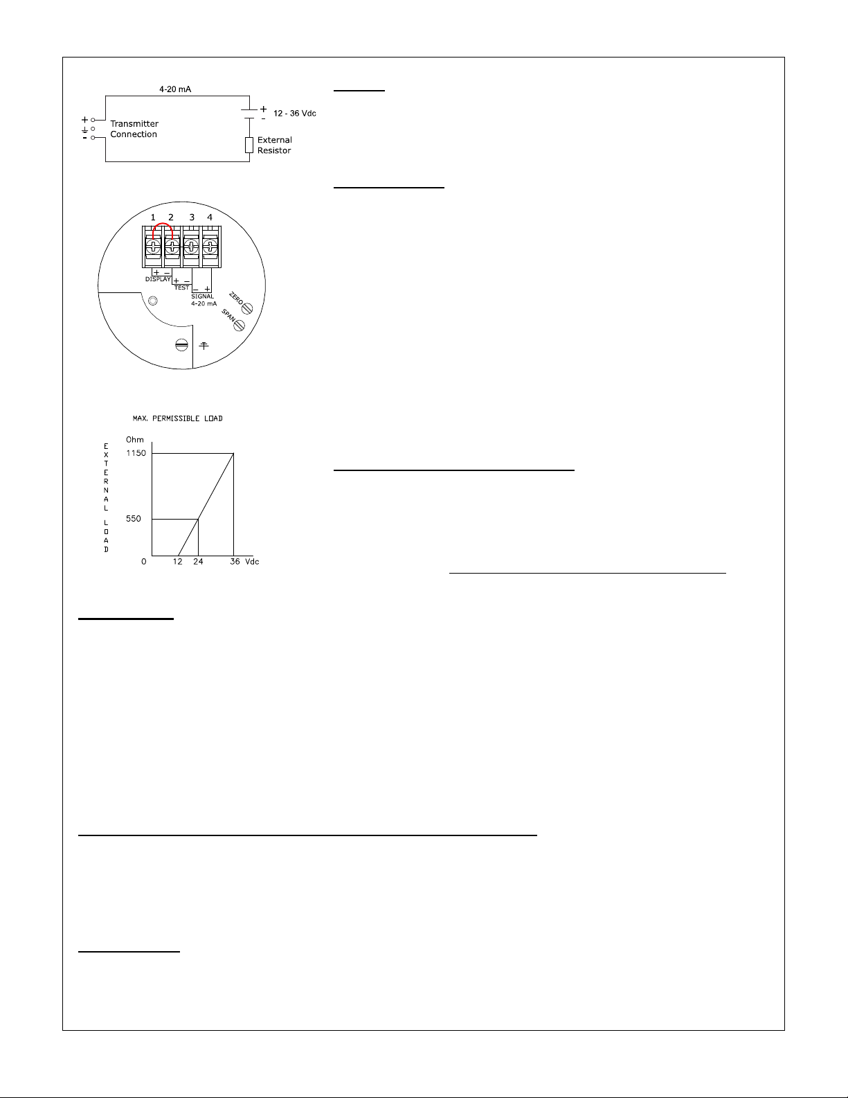
WIRING
The figure left shows the wiring connection of the PERAMIC.
The 2-wires must be connected to connectors 3 (-) and 4 (+).
In most circumstances the load should be placed in the negative
side of the 2-wire loop, although this it is not necessary.
TEST FUNCTION
Without interrupting the loop, the actual output (mA) of the transmitter
can be measured by connecting a multimeter to 2 (+) and 3 (-).
The transmitter must always be connected to earth.
The transmitter must be connected with standard two-wire shielded
cable. Do not run signal wiring in open trays with power wiring, or
near heavy electrical equipment (Frequency controllers or heavy
pumps). Shielding must always be connected at the side of the power
supply. In case the mounting position is already connected to ground
(by tank or pipe line) do not connect the instrument to ground. Please
ensure that the instrument is not connected to ground twice to
prevent the occurrence of an Earth loop.
Reversing the polarity will not damage the transmitter, but the
transmitter will not function until the wires are properly connected.
POWER SUPPLY / EXTERNAL LOAD
The minimum power supply is based on the total circuit resistance.
The maximum permissible load (Ri max.) in case of 24 Vdc will be 600
Ohm. By increasing the power supply, the external load can be higher,
till 1200 Ohm / 36 Vdc. (see figure left).
Ri max =
Power Supply - 13 Vdc (min. power supply
20 mA
)
CALIBRATION
All transmitters are fully calibrated at the factory, to customer specified range. When no calibration is requested,
the transmitter will be calibrated at the lowest span. It is advisable to recalibrate the transmitter after shipment.
The calibration sequence is as follows:
1. The output of the transmitter must be set at 4 mA (Zero-potentiometer).
2. Air pressure in accordance with the process pressure must be applied to the test nipple.
3. The output of the transmitter must be set at 20 mA (Span-potentiometer).
4. Remove the air pressure.
5. Check if the output of the transmitter is 4 mA. (Otherwise repeat steps 1 till 4)
6. Install transmitter (See above).
7. The output must be set at 4 mA (Dependable on mounting position).
COMPOUND RANGE (Combination overpressure and under pressure)
For example: if the transmitter is adjusted at –1.45 …+1.45 psi the output of the transmitter at atmospheric
pressure must be 12 mA. If not this must be corrected at 12 mA by turning the ZERO potentiometer. After this a
test pressure of 100 mbar should be put on the transmitter and the output should show 20 mA. If not this must
be set at 20 mA by turning the SPAN potentiometer. When the test pressure is removed the transmitter should
show 12 mA at atmospheric pressure. If not the above sequence should repeated.
INSTALLATION
When mounting the PERAMIC, use the same principles as used for manometers (gauge). We recommend
using shut-off valves and water trap pipes according to BS/DIN standards, especially on steam applications
and those applications where the process temperature will be higher than 212°F.
H/US/PERAMIC/05-2018/00 Klay Instruments

Page 3/4
DIGITAL LOCAL INDICATOR
The local indicator displays a digital value that is proportional to the pressure measured by the transmitter. The
full scale point may be set to any value between 0000 and 1999. The local indicator can be mounted afterwards.
Remove the bridge which is placed between connector (1) and (2). Connect the red (+) wire to (1) and the black
(-) wire to (2). When using a local indicator the minimum power supply must be 15.5 Vdc.
HAZARDOUS AREA
The PERAMIC is certified for applications in hazardous areas.
Certification: II 1G Ex ia IIC T4 Ga (intrinsically safe). When the PERAMIC is used in such areas, use a certified
power supply, from 13 - 26.5 Vdc. Installation of this device has to be carried out by a certified and qualified
mechanic or a certified and qualified installer.
CERTIFICATIONS
ATEX - II 1 G Ex ia IIC T4 Ga
Certificate : KEMA 03ATEX1219 X
Ui = 26.5 Vdc, Ii = 110 mA, Ci = 1 nF, Li = 1.2 mH, Pi = 0.9 W
-30° C < T
< 70° C (-22° F < T
amb
< 158° F)
amb
The X in the certificate number refers to a special condition only applicable for our submersible level transmitter
HYDROBAR-Cable and –FR. See for this conditions the ATEX-certificate.
IECEx - Ex ia IIC T4 Ga
Certificate: DEK 13.0060X
Ui = 26.5 Vdc, Ii = 110 mA, Ci = 1 nF, Li = 1.2 mH, Pi = 0.9 W
-30° C < T
< 70° C (-22° F < T
amb
< 158° F)
amb
All certifications are in compliance with IECEx scheme rules, and the International Standards :
IEC 60079-0:2011, IEC 60079-11:2011, IEC 60079-26:2007 and IEC 17050-1. They are certified for use in
hazardous areas by DEKRA B.V.
DO NOT REMOVE THE SCREW COVER WHEN AN EXPLOSIVE ATMOSPHERE MAY BE PRESENT.
FUNCTIONAL SAFETY - SIL
The device is certified as “Proven in use” for a Functional safety environment of SIL2 according
to IEC-61511 and SIL2 according to IEC-61508.
When ordered as a SIL (Proven in use) transmitter, the safety manual will be supplied. (Option G200)
Detailed information can be found in the Safety manual of the instrument. The most recent version of the Safety
manual is available on: www.klay-instruments.com under section Downloads.
Note 1 : According to IEC 61511, 11.4.4 SIL3 is possible in 1oo2 configuration (two-channel redundant architecture)
Note 2: Option SIL (Proven in use) is valid on transmitters with a serial number > 10509426
TRACEABILITY YEAR OF MANUFACTURING
The year of manufacturing of the transmitter can be traced as follows: take the first two numbers from the serial
number that is engraved in the transmitter and add 1908. For example: if the serial number is 10509426. The
year of manufacturing is 1908 + 105 = 2013. For older transmitters, for example with serial number 9302123,
the first two numbers must be add to 1908.
PROCESS TEMPERATURE
-4°F to +176°F
H/US/PERAMIC/05-2018/00 Klay Instruments

Page 4/4
Nijverheidsweg 5 7991 CZ DWINGELOO
P.O. Box 13 7990 AA DWINGELOO
Tel: +31-521-591550 The Netherlands
Fax: +31-521-592046 E-mail: info@klay.nl
PRECAUTIONS and WARNINGS:
Check if the specifications of the PERAMIC meet the needs of the process conditions.
The Ceramic Sensor in combination with the VITON O-Ring can withstand nearly all process fluids, gases and
vapors. Always check if Ceramic and VITON can be applied. Other O-Ring materials are available on request.
When the PERAMIC is mounted horizontal, be aware that the venting must be pointed downwards of the
electronic housing, all other mounting positions are not allowed.
When a flush diaphragm is needed, for food- or paper industry, use our transmitters Series 8000 or 8000-SAN.
When the PERAMIC is used as a pressure transmitter, be aware of the following points:
1. Rapid closing valves in combination with high flow velocity will cause water hammer(spikes) and can
destroy the transmitter. Do not mount the PERAMIC near such valves, always a few pipe bends away
up or down stream (avoid suction).
2. Place a pressure transmitter a few pipe bends away from pumps, as well on the suction or pressure
side of the pump.
When the PERAMIC is used as a level transmitter, be aware of the place where the transmitter is mounted. Here
are some advises:
1. DO NOT mount a level transmitter in or near filling or discharging pipes.
2. In case of automatic cleaning systems or hand cleaning: never point the water jets on the diaphragm,
take necessary steps to avoid this. Guarantee will not be granted.
As soon as the wiring is brought inside, through the PG9 Cable gland and connected to the terminal board,
make sure the cable gland is tightly fixed, so that moisture cannot enter into the electronic housing.
Never remove the venting (3), because it is especially designed to prevent moisture from entering into the
electronic housing. If the ambient conditions are very wet, we advise to use a venting through the cable. A
special vented cable can be delivered on request.
Avoid high pressure water jets pointed at the venting.
The cover must be fully engaged, so that moisture cannot ingress into the electronic housing. The cover must
only be capable of being released or removed with the aid of a tool.
WARRANTY: The warranty is 1 year after delivery.
Klay Instruments does not accept liability for consequential damage of any kind due to use or miss use of the
PERAMIC. Warranty will be given, to be decided by the manufacturer. Transmitter must be shipped prepaid to
the factory on manufacturer's authorization.
Klay Instruments reserves the right to change its specifications at any time, without notice.
Klay Instruments is not an expert in the customer's process (technical field) and therefore does
not warrant the suitability of its product for the application selected by the customer.
Manufactured by:
www.klay-instruments.com
H/US/PERAMIC/05-2018/00 Klay Instruments

EU-DECLARATION OF CONFORMITY
Klay Instruments B.V.
Nijverheidsweg 5, 7991 CZ Dwingeloo, The Netherlands
Certify that the equipment intended for use in potentially explosive atmospheres, only new products, indicated here
after:
Electronic Pressure- and Level Transmitters
Series 8000-SAN, Series 8000, Series CER-8000
Hydrobar-Cable, Hydrobar-EXTD, Hydrobar-FR
Are in accordance with:
-
Directive 2014/34/EU (Equipment and protective systems intended for use in potentially explosive atmospheres)
-
Directive 2014/30/EU (Electro Magnetic Compatibility).
-
Harmonized standards:
EN 60079-0: 2012 (General rules)
EN 60079-11: 2012 (Intrinsic safety “i”)
EN 60079-26:2007 (Group II cat. 1G requirements)
IEC 61000-6-2: 2001 (EMC, Immunity in industrial location)
IEC 61000-6-3: 2001 (EMC, Emission in industrial location)
IEC 61000-6-4: 2001 (EMC, Emission in industrial location)
EN-ISO-IEC 80079-34: 2011 (Potentially explosive atmospheres – Application of quality systems
-
The type (protection mode “ia”) which has been the subject of;
EC-type Examination Certificate Numbers:
KEMA 03 ATEX1219 X, Issue 5
Delivered by the KEMA, Meander 1051, 6825 MJ Arnhem, The Netherlands, Notified Body No. 0344.
Manufacturing plant in Dwingeloo which has been the subject of;
Production Quality Assurance Notification Number:
DEKRA 12ATEXQ0041, Issue 3
Delivered by the DEKRA, Meander 1051, 6825 MJ Arnhem, The Netherlands, Notified Body No. 0344.
Date: February 12th 2018
E. Timmer
Managing Director - Klay Instruments B.V.
Signature:
The marking of the equipment is as follows:
II 1G Ex ia IIC T4 Ga
‘’II’’
means that the equipment has been built for use in surface industries (and not in mines endangered by
firedamp).
‘’1’’
equipment for use in Zone 0 (if G)
‘’G’’
equipment for use with gas, vapours or mists
‘’Ex’’
equipment in compliance with European standards for
explosive atmospheres
‘’ia’’
equipment in compliance with specific building rules for intrinsically save equipment
‘’C’’
equipment for use with gas of subdivision C
‘’T4’’
equipment whose surface temperature does not exceed 135°C when used with ambient temperature < 70°C.
Protection Grade, Series 8000-SAN, 8000, CER-8000, IP 66
Protection Grade, Series Hydrobar-cable, Hydrobar-EXTD, IP 66
The Hydrobar-FR and all other submersible parts from the Series Hydrobar are IP 68.
Furthermore, whatever the protection mode, only use cable glands with a protection degree of at least IP 66.
Be sure the cable diameter complies with the selected cable gland. Tighten the cable gland in a proper way.
Never forget to mount the covers of the electronics housings in a proper way.
For other technical details, refer to the instruction manuals of the series transmitters.
Nijverheidsweg 5 7991 CZ Dwingeloo Tel.: +31 521 591550 The Netherlands
P.O. Box 13 7991 AA Dwingeloo Fax.: +31 521 592046 e-mail: info@klay.nl
EU-DOC/02-2018/11 -USA-
 Loading...